1
User manual
NIBE™ F470
Exhaust air heat pump
LEK
UHB GB 1537-2
231495
Quick guide
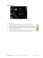
Navigation
Ok button (confirm/select)
Back button (back/undo/exit)
Control knob (move/increase/reduce)
A detailed explanation of the button functions can be found on page
11.
How to scroll through menus and make different settings is described
on page 15.
Set the indoor climate
2X
The mode for setting the indoor temperature is accessed by pressing
the OK button twice, when in the start mode in the main menu. Read
more about the settings on page 28.
To temporarily increase the amount of hot water, first turn the control
knob to mark menu 2 (water droplet) and then press the OK button
twice. Read more about the settings on page 43.
In event of disturbances in comfort
If a disturbance in comfort of any type occurs there are some measures
that can be taken before you need to contact your installer. See page
65 for instructions.
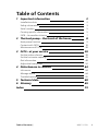
Table of Contents
1 Important information
Installation data
Safety information
Serial number
Country specific information
F470 – An excellent choice
2 The heat pump – the heart of the house
Heat pump function
Contact with F470
Maintenance of F470
3 F470 – at your service
2
2
3
5
5
7
8
9
10
20
28
Set the indoor climate
Set the hot water capacity
Get information
Adjust the heat pump
28
43
48
52
4 Disturbances in comfort
64
Info menu
Manage alarm
Troubleshooting
64
64
65
5 Technical data
6 Glossary
68
69
Index
73
Table of Contents |
NIBE™ F470
1
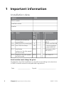
1 Important information
Installation data
Product
F470
Serial number
Installation date
Installer
No.
Name
1.1
1.9.1
1.9.3
temperature (heating
curve offset)
heating curve (curve slope)
min. flow line temp.
5.1.5
ventilation
5.1.6
Fact- Set
ory
settings
0
9
20
65%
exhaust air fan (fan speed,
normal mode)
Supply air fan (fan speed, 45%
normal mode)
✔ Accessories
Extra shunt ECS
40/41
Room unit RMU 40
Communications
module SMS 40
Docking kit DEH
40/DEH 41
Sun Solar 41
Serial number must always be given
Certification that the installation is carried out according to instructions
in NIBE's installer manual and applicable regulations.
Date
2
__________________
Chapter 1 | Important information
Signed
_________________________
NIBE™ F470
Safety information
This appliance can be used by children aged from 8
years and above and persons with reduced physical,
sensory or mental capabilities or lack of experience
and knowledge if they have been given supervision or
instruction concerning use of the appliance in a safe
way and understand the hazards involved. Children
shall not play with the appliance. Cleaning and user
maintenance shall not be made by children without
supervision.
Rights to make any design or technical modifications
are reserved.
©NIBE 2015.
NOTE
F470 must be installed via an isolator switch with a minimum breaking
gap of 3mm.
NOTE
If the supply cable is damaged, only NIBE, its service representative
or similar authorised person may replace it to prevent any danger
and damage.
Symbols
NOTE
This symbol indicates danger to machine or person.
Caution
This symbol indicates important information about what you should
observe when maintaining your installation.
TIP
This symbol indicates tips on how to facilitate using the product.
Chapter 1 | Important information
NIBE™ F470
3
Marking
F470 is CE marked and fulfils IP21.
The CE marking means that NIBE ensures that the product meets all regulations that are placed on it based on relevant EU directives. The CE mark
is obligatory for most products sold in the EU, regardless where they are
made.
IP21 means that objects with a diameter larger than or equivalent to 12.5
mm cannot penetrate and cause damage and that the product is protected
against vertically falling drops of water.
4
Chapter 1 | Important information
NIBE™ F470
Serial number
The serial number can be found at the bottom right of the front cover and
in the info menu (menu 3.1).
Serial number
Caution
Always give the product's serial number (14 digits) when reporting a
fault.
Country specific information
Great Britain
This installation is subject to building regulation approval, notify the local
Authority of intention to install.
Use only manufacturer’s recommended replacement parts.
Nibe is a licensed member of the Benchmark Scheme which aims to improve the standards of installation and commissioning of domestic heating
and hot water systems in the UK and to encourage regular servicing to
optimise safety, efficiency and performance.
Benchmark is managed and promoted by the Heating and Hotwater Industry Council. For more information visit www.centralheating.co.uk
Warranty and insurance information
Thank you for installing a new NIBE heat pump in your home.
NIBE heat pumps are manufactured in Sweden to the very highest standard
so we are pleased to offer our customers a comprehensive guarantee.
Chapter 1 | Important information
NIBE™ F470
5
The product is guaranteed for 24 months for parts and labour from the
date of installation or 33 months from the date of manufacture, whichever
is the shorter.
The NIBE guarantee is based on the unit being installed and commissioned
by a NIBE accredited installer, serviced every year and the Benchmark
documents completed. Where this condition is not met, any chargeable
spare parts or components issued within the applicable guarantee period
still benefit from a 12 month warranty from the date of issue by the
manufacturer.
We recommend the installer completes and returns as soon as possible,
your guarantee registration card or completes the guarantee form on the
NIBE website www.nibe.co.uk.
Please ensure that the installer has fully completed the Benchmark
Checklist in the end of the Installation Instructions supplied with the
product and that you have signed to say that you have received a full and
clear explanation of its operation. The installer is legally required to complete a commissioning checklist as a means of complying with the appropriate Building Regulations (England and Wales).
All installations must be notified to Local Area Building Control either
directly or through a Competent Persons Scheme. A Building Regulations
Compliance Certificate will then be issued to the customer who should,
on receipt, write the Notification Number on the Benchmark Checklist.
This product should be serviced regularly to optimise its safety, efficiency
and performance. The service engineer should complete the relevant
Service Record on the Benchmark Checklist after each service.
The Benchmark Checklist may be required in the event of any warranty
work and as supporting documentation relating to home improvements
in the optional documents section of the Home Information Pack.
6
Chapter 1 | Important information
NIBE™ F470
F470 – An excellent choice
F470 is part of a new generation of heat pumps, which have been introduced to supply your home with inexpensive and environmentally friendly
heating. Heat production is safe and economical with integrated hot water
heater, immersion heater, circulation pump and control system.
The heat pump can be connected to an optional low temperature heat
distribution system. e.g. radiators, convectors or under floor heating. It is
also prepared for connection to several different products and accessories,
e.g. extra water heater and climate systems with different temperatures.
F470 is equipped with a control computer for good comfort, good economy
and safe operation. Clear information about status, operation time and
all temperatures in the heat pump are shown on the large and easy to
read display. This means, for example, that external unit thermometers
are not necessary.
Excellent properties for F470:
■
Integrated water heater
There is a water heater integrated in the heat pump, which is insulated
with environmentally friendly cellular plastic for minimal heat loss.
■
Scheduling the indoor comfort and hot water
Heating and hot water as well as ventilation, can be scheduled for each
day of the week or for longer periods (vacation).
■
Display with user instructions
The heat pump has a large display with easy-to-understand menus that
facilitate setting a comfortable climate.
■
Simple troubleshooting
In the event of a fault, the heat pump display shows what happened
and the actions to be taken.
Chapter 1 | Important information
NIBE™ F470
7
2 The heat pump – the heart of
the house
H
H
Heating
medium
Värmebärare
Värmebärare
3
Köldmedium
Köldmedium
Refrigerant
I
Rumsluft
Köldbärare
Brine
45 °C
40 °C
55 °C
50 °C
G G
E
E
80 °C
100 °C
Condenser
Kondensor
Kondensor
Expansionsventil
Expansion
valve
Expansionsventil
F
F
0 °C
2
Kompressor
Compressor
Kompressor
Förångare
Evaporator
Förångare
D D
-2 °C5 °C
C C
B B
0 °C
-3 °C
0 °C22 °C
1
A A
Värmekälla
Heat source
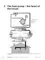
The temperatures are only examples and may vary between different installations and
time of year.
8
Chapter 2 | The heat pump – the heart of the house
NIBE™ F470
Heat pump function
An exhaust air heat pump makes use of the heat in the building's ventilation air to heat up the accommodation. The conversion of the ventilation
air's energy to accommodation heating is done in three different circuits.
From the outgoing ventilation air (1), free heating energy is retrieved from
the accommodation and transported to the heat pump. The heat pump
increases the retrieved heat's low temperature to a high temperature in
the refrigerant circuit, (2). The heat is distributed around the building in
the heating medium circuit (3).
A
B
C
D
E
F
G
H
I
Ventilation air
The hot air is transferred from the rooms to the heat pump via the house
ventilation system.
The fan then routes the air to the heat pump’s evaporator. Here, the air
releases the heating energy and the air's temperature drops significantly.
The cold air is then blown out of the house.
Refrigerant circuit
A liquid, a refrigerant, circulates in a closed system in the heat pump which
also passes the evaporator. The refrigerant has a very low boiling point.
In the evaporator the refrigerant receives the heat energy from the ventilation air and starts to boil.
The gas that is produced during boiling is routed into an electrically
powered compressor. When the gas is compressed, the pressure increases
and the gas's temperature increases considerably, from approx. 5 °C to
approx. 80°C.
From the compressor, gas is forced into a heat exchanger, condenser,
where it releases heat energy to the heat pump boiler section, whereupon
the gas is cooled and condenses to a liquid form again.
As the pressure is still high, the refrigerant can pass an expansion valve,
where the pressure drops so that the refrigerant returns to its original
temperature. The refrigerant has now completed a full cycle. It is routed
to the evaporator again and the process is repeated.
Heat medium circuit
The heat energy that the refrigerant produces in the condenser is retrieved
by the climate system's water, heating medium, which is heated to 35 °C
(supply temperature).
The hot water circulates in a closed system and is pumped out to the radiators/heating coils of the house and to the heat pump supply air coil. The
supply air battery heats up the air that is blown out into the room with
the supply air device.
The heat pump's integrated hot water heater is in the boiler section. The
hot boiler water heats the hot water.
Chapter 2 | The heat pump – the heart of the house
NIBE™ F470
9
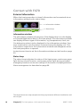
Contact with F470
External information
When the heat pump door is closed, information can be received via an
information window and a status lamp.
Information window
Status lamp
Information window
The information window shows part of the display that is on the display
unit (located behind the door to the heat pump). The information window
can display different type of information, e.g. temperatures, clock, etc.
You determine what is to be displayed in the information window. Your
own combination of information is entered using the display unit. This
information is specific to the information window and disappears when
the heat pump door is opened.
Instructions on how to set the information window can be found on page
59.
Status lamp
The status lamp indicates the status of the heat pump: continuous green
light during normal function, continuous yellow light during activated
emergency mode or continuous red light in the event of a deployed alarm.
Alarm management is described on page 64.
The temperatures are only examples and may vary between different installations and
time of year.
10
Chapter 2 | The heat pump – the heart of the house
NIBE™ F470
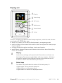
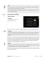
Display unit
INDOOR CLIMATE
HEAT PUMP
HOT WATER
INFO
A Display
B Status lamp
C
OK button
D Back button
F470
E
Control knob
F
Switch
There is a display unit behind the heat pump door, which is used to communicate with F470. Here you:
■ switch on, switch off or set the heat pump in emergency mode.
■ sets the indoor climate and hot water as well as adjusts the heat pump
to your needs.
■ receive information about settings, status and events.
■ see different types of alarms and receive instructions about how they
are to be rectified.
A
Display
B
Status lamp
Instructions, settings and operational information are shown on
the display. The easy-to-read display and menu system, facilitates
navigation between the different menus and options to set the
comfort or obtain the information you require.
The status lamp indicates the status of the heat pump. It:
■ lights green during normal operation.
■ lights yellow in emergency mode.
■ lights red in the event of a deployed alarm.
Chapter 2 | The heat pump – the heart of the house
NIBE™ F470
11
C
OK button
D
Back button
E
Control knob
F
Switch
The OK button is used to:
■ confirm selections of sub menus/options/set values/page in the
start guide.
The back button is used to:
■ go back to the previous menu.
■ change a setting that has not been confirmed.
The control knob can be turned to the right or left. You can:
■ scroll in menus and between options.
■ increase and decrease the values.
■ change page in multiple page instructions (for example help text
and service info).
The switch assumes three positions:
■ On ( )
■ Standby ( )
■ Emergency mode (
)
Emergency mode must only be used in the event of a fault on the
heat pump. In this mode, the compressor and fans switch off and
the immersion heater engages. The heat pump display is not illuminated and the status lamp illuminates yellow.
The automatic heating control system is not operational, so manual
shunt operation is required (see page 25).
G
USB port
The USB port is hidden beneath the plastic badge with the product
name on it.
The USB port is used to update the software.
Visit http://www.nibeuplink.com and click the "Software" tab to
download the latest software for your installation.
12
Chapter 2 | The heat pump – the heart of the house
NIBE™ F470
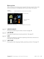
Menu system
When the door to the heat pump is opened, the menu system’s four main
menus are shown in the display as well as certain basic information.
Outdoor
temperature
Indoor temperature - (if room sensors are installed)
INDOOR CLIMATE
HOT WATER
Hot water temp.
Information about
operation
SERVICE
HEAT PUMP
Temporary lux (if activated)
Menu 1
INFO
Estimated amount of hot water
INDOOR CLIMATE
Setting and scheduling the indoor climate. See page 28.
Menu 2
HOT WATER
Setting and scheduling hot water production. See page 43.
Menu 3
INFO
Display of temperature and other operating information and access to
the alarm log. See page 48.
Menu 4
HEAT PUMP
Setting time, date, language, display, operating mode etc. See page 52.
Chapter 2 | The heat pump – the heart of the house
NIBE™ F470
13
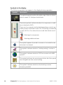
Symbols in the display
The following symbols can appear in the display during operation.
Symbol
Description
This symbol appears by the information sign if there is information in menu 3.1 that you should note.
These two symbols indicate whether the compressor or addition is blocked in F470.
These can, for example, be blocked depending on which operating mode is selected in menu 4.2, if blocking is scheduled
in menu 4.9.5 or if an alarm has occurred that blocks one of
them.
Blocking the compressor.
Blocking additional heat.
This symbol appears if periodic increase or lux mode for the
hot water is activated.
This symbol indicates whether "holiday setting" is active in
4.7.
This symbol indicates whether F470 has contact with NIBE
Uplink™.
This symbol indicates the actual speed of the fan if the speed
has changed from the normal setting.
This symbol indicates whether solar heating is active.
Accessory needed.
14
Chapter 2 | The heat pump – the heart of the house
NIBE™ F470
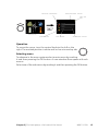
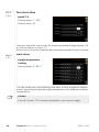
Menu number – marked sub menu
Name and menu number – main menu
Symbol – main
menu
INDOOR CLIMATE
HOT WATER
INDOOR CLIMATE 1
temperature
ventilation
normal
scheduling
off
advanced
HEAT PUMP
INFO
Marked main menu
Symbols – sub menus
Name – sub menus
Status information – sub menus
Operation
To move the cursor, turn the control knob to the left or the
right. The marked position is white and/or has a turned up tab.
Selecting menu
To advance in the menu system select a main menu by marking
it and then pressing the OK button. A new window then opens with sub
menus.
Select one of the sub menus by marking it and then pressing the OK button.
Chapter 2 | The heat pump – the heart of the house
NIBE™ F470
15
Selecting options
comfort mode2.2
economy
normal
luxury
Alternative
In an options menu the current selected option is indicated by a green
tick.
To select another option:
1. Mark the applicable option. One of the options is pre-selected
(white).
2. Press the OK button to confirm the selected option. The selected
option has a green tick.
16
Chapter 2 | The heat pump – the heart of the house
NIBE™ F470
Setting a value
time & date4.4
time
24 h
12 h
date
day
month
year
Values to be changed
To set a value:
1. Mark the value you want to set using the control knob.
2. Press the OK button. The background of the value becomes
green, which means that you have accessed the setting mode.
3. Turn the control knob to the right to increase the value and to
the left to reduce the value.
4. Press the OK button to confirm the value you have set. To change
and return to the original value, press the Back button.
Chapter 2 | The heat pump – the heart of the house
NIBE™ F470
17
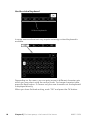
Use the virtual keyboard
Different keyboards
In some menus where text may require entering, a virtual keyboard is
available.
Depending on the menu, you can gain access to different character sets
which you can select using the control knob. To change character table,
press the Back button. If a menu only has one character set the keyboard
is displayed directly.
When you have finished writing, mark "OK" and press the OK button.
18
Chapter 2 | The heat pump – the heart of the house
NIBE™ F470
Scroll through the windows
A menu can consist of several windows. Turn the control knob to scroll
between the windows.
Current menu
window
Number of windows
in the menu
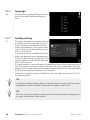
Scroll through the windows in the start guide
language 4.6
Arrows to scroll through window in start guide
1. Turn the control knob until one of the arrows in the top left corner (at
the page number) has been marked.
2. Press the OK button to skip between the steps in the start guide.
Help menu
In many menus there is a symbol that indicates that extra help is
If theavailable.
start guide is left on this page it closes
automatically in
To access the help text:
60 min
1. Use the control knob to select the help symbol.
2. Press the OK button.
The help text often consists of several windows that you can scroll between
using the control knob.
Chapter 2 | The heat pump – the heart of the house
NIBE™ F470
19
Maintenance of F470
Regular checks
All servicing must be carried out by a person competent for the job.
Your heat pump requires minimal maintenance after commissioning.
However, it is recommended that your installation is checked and serviced
annually by qualified personnel. This is to ensure the continued efficient
operation of your heat pump, and that the warranty remains valid during
the warranty period.
If something unusual occurs, messages about the malfunction appear in
the display in the form of different alarm texts. See alarm management
on page 64.
Service hatch
Behind the service hatch are the safety valves, circulation pump etc. Remove
the hatch by pulling it towards you.
LEK
Cleaning the ventilation devices
The building’s ventilation devices should be
cleaned regularly with, for example, a small
brush to maintain the correct ventilation.
The device settings must not be changed.
Also check the outdoor air's intake grilles on
the house facade and clean if necessary.
NOTE
If you take down more than one ventilation
device for cleaning, do not mix them up.
20
Chapter 2 | The heat pump – the heart of the house
NIBE™ F470
Cleaning the air filter
Clean the F470's air filters regularly, how often depends on the amount
of dust in the ventilation air. Select what is most suitable for your heat
pump.
You will receive a reminder about filter cleaning in the display. The default
setting for the reminder is every three months, however, if the power to
F470 is interrupted the countdown begins again.
1. Switch off the heat pump.
2. Remove the upper front cover by pulling straight out.
3. Pull out the filter cassette.
4. Take out the filter and shake/vacuum off any dirt. Do not use water
or other liquids for cleaning.
5. Check that the filter is not damaged.
6. Carry out assembly in reverse order.
Even if the filter appears clean, dirt collects in it and this affects the efficiency of the filter. Therefore, replace it after 2 years. New filters can be
ordered via the installer.
Filter
LEK
Chapter 2 | The heat pump – the heart of the house
NIBE™ F470
21
Check pressure
F470 has a pressure gauge which shows the heating system pressure. The
pressure should be between 0.5 and 1.5 bar, but varies during temperature
changes. If the pressure drops to 0 or rises to 2.5 frequently, contact your
installer for troubleshooting.
Pressure gauge
LEK
LEK
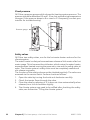
Safety valves
F470 has two safety valves, one for the hot water heater and one for the
climate system.
The water heater's safety valve sometimes releases a little water after hot
water usage. This is because the cold water, which enters the water heater,
expands when heated causing the pressure to rise and the safety valve to
open. The climate system's safety valve must be completely sealed and
not release any water.
The function of the safety valves must be checked regularly. The valves are
accessed via the service hatch. Perform checks as follows:
1. Open the valve by turning the knob anti-clockwise carefully.
2. Check that water flows through the valve.
3. Close the valve by releasing it. If it does not close automatically when
released, turn it anti-clockwise slightly.
4. The climate system may need to be refilled after checking the safety
valve, see the section “Filling the climate system”.
22
Chapter 2 | The heat pump – the heart of the house
NIBE™ F470
Safety valve for climate system
LEK
LEK
LEK
Safety valve for water heater
NOTE
Do not remove or adjust any components that are part of this pressurised
water heater. Contact your installer!
NOTE
If this pressurised water heater develops a fault, e.g. a flow of hot water
from the overflow pipe, turn the heat pump off and contact your installer.
Chapter 2 | The heat pump – the heart of the house
NIBE™ F470
23
Filling the climate system
If the pressure is too low, increase as follows:
1. Check if the flexi hose supplied is connected between the two filler
valves. Adjust the hose if this has not been done.
2. Open the filler valves. The boiler unit and the rest of the climate system
are filled with water.
3. After a while the pressure rises on the pressure gauge. When it is approx. 1.0 bar close the filler valves.
Filler valve 2
Vent valve, supply air coil
Pressure gauge
LEK
LEK
LEK
Filler valve 1
Venting valve
Venting the climate system
In event of repeated filling of the climate system or if bubbling sounds are
heard from the heat pump the system may need venting. This is carried
out as follows:
1. Turn off the power supply to the heat pump.
2. Vent the heat pump via the vent valve and the rest of the climate system via the relevant vent valves.
3. Vent the supply air battery via its vent valve.
NOTE
The vent pipe from the container must be drained of water before air
can be released. This means that the system is not necessarily bled despite
the flow of water when the bleed valve is opened.
Therefore hold the vent valve open for at least 5 seconds.
24
Chapter 2 | The heat pump – the heart of the house
NIBE™ F470
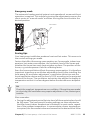
Emergency mode
The automatic heating control system is not operational, so manual shunt
operation is required. This is done by turning the adjustment screw on the
shunt motor to "manual mode" and then turning the shunt knob to the
desired position.
LEK
Shunt motor
LEK
Adjuster screw
Saving tips
Your heat pump installation produces heat and hot water. This occurs via
the control settings you made.
Factors that affect the energy consumption are, for example, indoor temperature, hot water consumption, the insulation level of the house and
whether the house has many large window surfaces. The position of the
house, e.g. wind exposure is also an affecting factor.
Even the house ventilation affects the energy consumption. It is therefore
important to perform a ventilation adjustment shortly after installing the
heat pump. At ventilation adjustment, a ventilation technician sets the
house ventilation device and the fans in F470, according to the projected
values of the house. The ventilation technician also adjusts the supply air
temperature so that it is a few degrees below the desired room temperature.
TIP
Check the supply air temperature on a cold day. If the setting was made
on a hot day, the ventilation may require adjustment. If so, contact your
installer.
Also remember:
■ During the adjustment period (winter time) all thermostat valves should
be fully open. The heat pump's heating settings are then adjusted so
that the correct indoor temperature is obtained, in most rooms, regardless of the outdoor temperature. In rooms where a lower temperature
is required, the thermostat valves are lowered to the desired level. After
Chapter 2 | The heat pump – the heart of the house
NIBE™ F470
25
a few months, the remaining thermostats can be lowered slightly to
avoid an increase of the room temperature due to solar radiation, stove
heat etc. Further reductions may be required later on.
■ You can lower the temperature when away from the house by
scheduling "holiday setting" in menu 4.7. See page 60 for instructions.
■ You can reduce the ventilation speed when you are away by entering
a schedule in menu 1.3.3. See page 32 for instructions.
■ If you activate "Hot water Economy", less energy is used.
Power consumption
Increasing the indoor temperature one degree increases the energy consumption by approx. 5%.
Domestic electricity
In the past it has been calculated that an average Swedish household has
an approximate annual consumption of 5000 kWh domestic electricity/year. In today's society it is usually between 6000-12000 kWh/year.
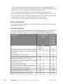
Equipment
TV (Operation: 5 h/day, Standby: 19 h/day)
Digital box (Operation: 5 h/day, Standby:
19 h/day)
DVD (Operation: 2 h/week)
TV games console (Operation: 6 h/week)
Radio/stereo (Operation: 3 h/day)
Computer incl. screen (Operation: 3 h/day,
standby 21 h/day)
Bulb (Operation 8 h/day)
Spot light, Halogen (Operation 8 h/day)
Cooling (Operation: 24 h/day)
Freezer (Operation: 24 h/day)
Stove, hob (Operation: 40 min/day)
Stove, oven (Operation: 2 h/week)
26
Normal Output
(W)
Approx.
annual
consumption
(kWh)
Operation
200
11
Standby
2
10
380
90
15
160
40
100
5
2
1
2
45
67
50
120
60
20
100
120
1500
3000
-
175
58
165
380
365
310
Chapter 2 | The heat pump – the heart of the house
NIBE™ F470
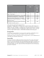
Equipment
Normal Output
(W)
Approx.
annual
consumption
(kWh)
Dishwasher, cold water connection (Operation 1 time/day)
Washing machine (Operation: 1 times/day)
Tumble drier (Operation: 1 times/day)
Vacuum cleaner (Operation: 2 h/week)
Engine block heater (Operation: 1 h/day, 4
months a year)
Passenger compartment heater (Operation:
1 h/day, 4 months a year)
2000
-
730
2000
2000
1000
400
-
730
730
100
50
800
-
100
These values are approximate example values.
Example: A family with 2 children live in a house with 1 flat-screen TV, 1
digital box, 1 DVD player, 1 TV games console, 2 computers, 3 stereos, 2
bulbs in the WC, 2 bulbs in the bathroom, 4 bulbs in the kitchen, 3 bulbs
outside, a washing machine, tumble drier, fridge, freezer, oven, vacuum
cleaner, engine block heater = 6240 kWh domestic electricity/year
Energy meter
Check the accommodation's energy meter regularly, preferably once a
month. This will indicate any changes in power consumption.
Newly built houses usually have twin energy meters, use the difference to
calculate your domestic electricity.
New builds
Newly built houses undergo a drying out process for a year. The house
can then consume significantly more energy than it would thereafter.
After 1-2 years the heating curve should be adjusted again, as well as the
offset heating curve and the building's thermostat valves, because the
heating system, as a rule, requires a lower temperature once the drying
process is complete.
Chapter 2 | The heat pump – the heart of the house
NIBE™ F470
27
3 F470 – at your service
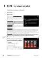
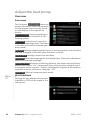
Set the indoor climate
Overview
Sub-menus
For the menu INDOOR CLIMATE
there are several sub-menus. Status
information for the relevant menu can
be found on the display to the right
of the menus.
temperature Setting the temperature
for the climate system. The status information shows the set values for the
climate system.
INDOOR CLIMATE 1
temperature
ventilation
normal
scheduling
off
advanced
ventilation Setting the fan speed. The
status information shows the selected
setting.
scheduling Scheduling heating and ventilation. Status information "set"
is displayed if you set a schedule but it is not active now, "holiday setting"
is displayed if the vacation schedule is active at the same time as the
schedule (the vacation function is prioritised), "active" displays if any part
of the schedule is active, otherwise it displays "off".
advanced Setting of heat curve, adjusting with external contact, minimum
value for supply temperature, room sensor and night cooling.
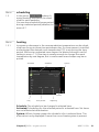
Menu
1.1
temperature
temperature heating1.1.1
Set the temperature (with room
sensors installed and activated):
heating
Setting range: 5 – 30 °C
Default value: 20
The value in the display appears as a
temperature in °C if the climate system is controlled by a room sensor.
28
Chapter 3 | F470 – at your service
NIBE™ F470
Caution
A slow heat-releasing heating system, such as for example, underfloor
heating, may not be suitable for control using the heat pump's room
sensor.
To change the room temperature, use the control knob to set the desired
temperature in the display. Confirm the new setting by pressing the OK
button. The new temperature is shown on the right-hand side of the
symbol in the display.
Setting the temperature (without room sensors activated):
Setting range: -10 to +10
Default value: -1
The display shows the set values for heating (curve offset). To increase or
reduce the indoor temperature, increase or reduce the value on the display.
Use the control knob to set a new value. Confirm the new setting by
pressing the OK button.
The number of steps the value has to be changed to achieve a degree
change of the indoor temperature depends on the heating installation.
One step is usually enough but in some cases several steps may be required.
Setting the desired value. The new value is shown on the right-hand side
of the symbol in the display.
Caution
An increase in the room temperature can be slowed by the thermostats
for the radiators or under floor heating. Therefore, open the thermostats
fully, except in those rooms where a cooler temperature is required, e.g.
bedrooms.
If the exhaust air temperature falls below 16 °C the compressor is blocked
and electric additional heat is permitted. Heat is not recovered from the
exhaust air when the compressor is blocked.
Chapter 3 | F470 – at your service
NIBE™ F470
29
TIP
Wait 24 hours before making a new setting, so that the room temperature has time to stabilise.
If it is cold outdoors and the room temperature is too low, increase the
curve slope in menu 1.9.1.1 by one increment.
If it is cold outdoors and the room temperature is too high, reduce the
curve slope in menu 1.9.1.1 by one increment.
If it is warm outdoors and the room temperature is too low, increase
the value in menu 1.1.1 by one increment.
If it is warm outdoors and the room temperature is too high, reduce the
value in menu 1.1.1 by one increment.
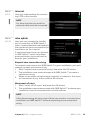
Menu
1.2
ventilation
Setting range: normal and speed
1-4
ventilation1.2
Default value: normal
normal(50%)
speed 1 (0%)
speed 2 (40%)
speed 3 (80%)
speed 4 (100%)
The ventilation in the accommodation can be temporarily increased or
reduced here.
When you have selected a new speed a clock starts a count down. When
the time has counted down the ventilation speed returns to the normal
setting.
If necessary, the different return times can be changed in menu 1.9.6.
The fan speed is shown in brackets (in percent) after each speed alternative.
TIP
If longer time changes are required use the holiday function or
scheduling.
30
Chapter 3 | F470 – at your service
NIBE™ F470
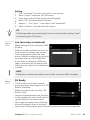
Menu
1.3
scheduling
scheduling 1.3
In the menu scheduling indoor climate (heating/ventilation) is scheduled for each weekday.
You can also schedule a longer period
during a selected period (vacation) in
menu 4.7.
Menu
1.3.1
heating
off
ventilation
off
heating
Increases or decreases in the accommodation temperature can be scheduled here for up to three time periods per day. If a room sensor is installed
and activated the desired room temperature (°C) is set during the time
period. Without an activated room sensor the desired change is set (of
setting in menu 1.1). One step is usually enough to change the room
temperature by one degree, but in some cases several steps may be required.
Activated
Schedule
SCHEDULING HEATING
schedule 1
schedule 2
activated
System
1.3.1
schedule 3
system
all
mon
tues
we
thur
fri
21:30 - 06:00
20.5°
sat
sun
Conflict
Day
Time period
Adjusting
Schedule: The schedule to be changed is selected here.
Activated: Scheduling for the selected period is activated here. Set times
are not affected at deactivation.
System: Which climate system the schedule is for is selected here. This
alternative is only displayed if more than one climate system is present.
Chapter 3 | F470 – at your service
NIBE™ F470
31
Day: Select which day or days of the week the schedule is to apply to here.
To remove the scheduling for a particular day, the time for that day must
be reset by setting the start time to the same as the stop time. If the line
"all" is used, all days in the period are set for these times.
Time period: The start and stop time for the selected day for scheduling
are selected here.
Adjusting: How much the heating curve is to be offset in relation to menu
1.1 during scheduling is set here. If the rooms sensor is installed the desired
room temperature is set in °C.
Conflict: If two settings conflict with each other a red exclamation mark
is displayed.
TIP
If you wish to set similar scheduling for every day of the week start by
filling in “all” and then changing the desired days.
TIP
Set the stop time earlier than the start time so that the period extends
beyond midnight. Scheduling then stops at the set stop time the day
after.
Scheduling always starts on the date that the start time is set for.
Caution
Changes of temperature in accommodation take time. For example,
short time periods in combination with underfloor heating will not give
a noticeable difference in room temperature.
If the exhaust air temperature falls below 16 °C the compressor is blocked
and electric additional heat is permitted. When the compressor is blocked
heat is not recovered from the exhaust air.
Menu
1.3.3
32
ventilation
Increases or decreases in the ventilation to the accommodation can be
scheduled here for up to two time periods per day.
Chapter 3 | F470 – at your service
NIBE™ F470
Schedule
Activated
SCHEDULING VENTILATION
schedule 1
1.3.3
schedule 2
activated
all
mon
tues
we
thur
fri
21:30 - 06:00
speed 3
sat
sun
Conflict
Day
Time period
Adjusting
Schedule: The schedule to be changed is selected here.
Activated: Scheduling for the selected period is activated here. Set times
are not affected at deactivation.
Day: Select which day or days of the week the schedule is to apply to here.
To remove the scheduling for a particular day, the time for that day must
be reset by setting the start time to the same as the stop time. If the line
"all" is used, all days in the period are set for these times.
Time period: The start and stop time for the selected day for scheduling
are selected here.
Adjusting: The desired fan speed is set here.
Conflict: If two settings conflict with each other a red exclamation mark
is displayed.
TIP
If you wish to set similar scheduling for every day of the week start by
filling in “all” and then changing the desired days.
TIP
Set the stop time earlier than the start time so that the period extends
beyond midnight. Scheduling then stops at the set stop time the day
after.
Scheduling always starts on the date that the start time is set for.
Chapter 3 | F470 – at your service
NIBE™ F470
33
Caution
A significant change over a longer period of time may cause poor indoor
environment and worse operating economy.
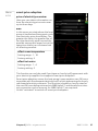
Menu
1.9
advanced
Menu advanced has orange text and
is intended for the advanced user. This
menu has several sub-menus.
advanced 1.9
heating curve
heating curve Setting the heating
curve slope.
external adjustment
external adjustment Setting the heat
curve offset when the external contact
is connected.
room sensor settings
min. flow line temp. Setting minimum permitted flow line temperature.
min. flow line temp.
fan return time
own curve
room sensor settings Settings regarding the room sensor.
fan return time Fan return time settings in the event of temporary ventilation speed change.
own curve Setting own heat curve.
point offset Setting the offset of the heating curve at a specific outdoor
temperature.
night cooling Setting night cooling.
Menu
1.9.1
heating curve
heating curve
heating curve 1.9.1.1
Setting range: 0 - 15
Default value: 5
system
flow temperature °C
outdoor temp. °C
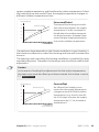
The prescribed heating curve for your house can be viewed in the
menu heating curve . The task of the heating curve is to give an even indoor
temperature, regardless of the outdoor temperature, and thereby energy
efficient operation. It is from this heating curve that the heat pump's
control computer determines the temperature of the water to the heating
34
Chapter 3 | F470 – at your service
NIBE™ F470
system, supply temperature, and therefore the indoor temperature. Select
the heating curve and read off how the supply temperature changes at
different outdoor temperatures here.
Curve coefficient
FRAMLEDNINGSTEMPERATUR
Supply temperature
°C
70
The slope of the heating curve indicates how many degrees the supply
temperature is to be increased/reduced when the outdoor temperature drops/increases. A steeper slope
means a higher supply temperature
at a certain outdoor temperature.
Steeper
curve slope
Brantare
kurvlutning
60
50
40
30
10
0
- 10
- 20
- 30
- 40°C
UTETEMPERATUR
Outdoor
temperature
The optimum slope depends on the climate conditions in your location, if
the house has radiators or under floor heating and how well insulated the
house is.
The heating curve is set when the heating installation is installed, but may
need adjusting later. Thereafter the heating curve should not need further
adjustment.
Caution
In the event of making fine adjustments for the indoor temperature,
the heat curve must be offset up or down instead, this is done in menu
1.1 temperature .
Curve offset
FRAMLEDNINGSTEMPERATUR
Supply temperature
°C
70
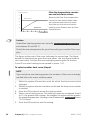
An offset of the heating curve
means that the supply temperature
changes as much for all the outdoor
temperatures, e.g. that a curve offset of +2 steps increases the supply
temperature by 5 C at all outdoor
temperatures.
Offset heating
curve
Förskjuten
värmekurva
60
50
40
30
10
0
- 10
- 20
- 30
- 40°C
UTETEMPERATUR
Outdoor
temperature
Chapter 3 | F470 – at your service
NIBE™ F470
35
Flow line temperature– maximum and minimum values
FRAMLEDNINGSTEMPERATUR
Supply temperature
°C
70
60
Because the flow line temperature
cannot be calculated higher than
the set maximum value or lower
than the set minimum value the
heating curve flattens out at these
temperatures.
Maximum
value
Maximivärde
50
40
30
Minimum
value
Minimivärde
10
0
- 10
- 20
- 30
- 40°C
UTETEMPERATUR
Outdoor
temperature
Caution
Underfloor heating systems are normally max flow line temperature
set between 35 and 45 °C.
Check the max temperature for your floor with your installer/floor supplier.
The figure at the end of the curve indicates the curve slope. The figure
beside the thermometer gives the curve offset. Use the control knob to
set a new value. Confirm the new setting by pressing the OK button.
Curve 0 is an own heating curve created in menu 1.9.7.
To select another heat curve (slope):
NOTE
If you only have one heating system, the number of the curve is already
marked when the menu window opens.
1. Select the system (if more than one) for which the heat curve is to be
changed.
2. When the system selection has been confirmed the heat curve number
is marked.
3. Press the OK button to access the setting mode
4. Select a new heating curve. The heating curves are numbered from 0
to 15, the greater the number, the steeper the slope and the greater
the supply temperature. Heating curve 0 means that own curve (menu
1.9.7) is used.
5. Press the OK button to exit the setting.
36
Chapter 3 | F470 – at your service
NIBE™ F470
To read off a heating curve:
1. Turn the control knob so that the ring on the shaft with the outdoor
temperature is marked.
2. Press the OK button.
3. Follow the grey line up to the heat curve and out to the left to read
off the value for the supply temperature at the selected outdoor
temperature.
4. You can now select to take read outs for different outdoor temperatures by turning the control knob to the right or left and read off the
corresponding flow temperature.
5. Press the OK or Back button to exit read off mode.
TIP
Wait 24 hours before making a new setting, so that the room temperature has time to stabilise.
If it is cold outdoors and the room temperature is too low, increase the
curve slope by one increment.
If it is cold outdoors and the room temperature is too high, lower the
curve slope by one increment.
If it is warm outdoors and the room temperature is too low, increase
the curve offset by one increment.
If it is warm outdoors and the room temperature is too high, lower the
curve offset by one increment.
Chapter 3 | F470 – at your service
NIBE™ F470
37
Menu
1.9.2
external adjustment
climate system
external adjustment1.9.2
Setting range: -10 to +10 or desired
room temperature if the room
sensor is installed.
climate system 1
Default value: 0
climate system 2
climate system 3
°C
°C
climate system 4
Connecting an external contact, for example, a room thermostat or a timer
allows you to temporarily or periodically raise or lower the room temperature while heating. When the contact is on, the heating curve offset is
changed by the number of steps selected in the menu. If a room sensor is
installed and activated the desired room temperature (°C) is set.
If there is more than one climate system the setting can be made separately
for each system.
Menu
1.9.3
min. flow line temp.
heating
min. flow line temp.1.9.3
Setting range: 20-70 °C
Default value: 20 °C
climate system 1
20 °C
climate system 2
20 °C
climate system 3
20 °C
climate system 4
20 °C
Set the minimum temperature on the supply temperature to the climate
system. This means that F470 never calculates a temperature lower than
that set here.
If there is more than one climate system the setting can be made separately
for each system.
38
Chapter 3 | F470 – at your service
NIBE™ F470
TIP
The value can be increased if you have, for example, a cellar that you
always want to heat, even in summer.
You may also need to increase the value in "stop heating" menu 4.9.2
"auto mode setting".
Menu
1.9.4
room sensor settings
factor system
heating
Setting range: 0.0 - 6.0
Default value: 2.0
room sensor settings 1.9.4
control room sensor syst 1
factor system 1
control room sensor syst 2
control room sensor syst 3
factor system 3
control room sensor syst 4
Room sensors to control the room temperature can be activated here.
Caution
A slow heat-releasing heating system, such as for example, underfloor
heating, may not be suitable for control using the heat pump's room
sensor.
Here you can set a factor (a numerical value) that determines how much
an over or sub normal temperature (the difference between the desired
and actual room temperature) in the room is to affect the supply temperature to the climate system. A higher value gives a greater and faster
change of the heating curve's set offset.
NOTE
Too high a set value for "factor system" can (depending on your climate
system) produce an unstable room temperature.
If several climate systems are installed the above settings can be made for
the relevant systems.
Chapter 3 | F470 – at your service
NIBE™ F470
39
Menu
1.9.6
fan return time
speed 1-4
fan return time1.9.6
Setting range: 1 – 99 h
Default value: 4 h
speed 1
hrs
speed 2
hrs
speed 3
hrs
speed 4
hrs
Here you select the return time for temporary speed change (speed 1-4)
on the ventilation in menu 1.2.
Return time is the time it takes before ventilation speed returns to normal.
Menu
1.9.7
own curve
supply temperature
heating
Setting range: 0 – 80 °C
own curve 1.9.7
flow line temp. at -30 °C
°C
flow line temp. at -20 °C
°C
flow line temp. at -10 °C
°C
flow line temp. at 0 °C
°C
flow line temp. at 10 °C
°C
flow line temp. at 20 °C
°C
You can create your own heating curve here, if there are special requirements, by setting the desired supply temperatures for different outdoor
temperatures.
Caution
Curve 0 in menu 1.9.1 must be selected for own curve to apply.
40
Chapter 3 | F470 – at your service
NIBE™ F470
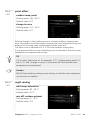
Menu
1.9.8
point offset
outdoor temp. point
point offset1.9.8
Setting range: -40 – 30 °C
Default value: 0 °C
change in curve
Setting range: -10 – 10 °C
outdoor temp. point
°C
change in curve
°C
flow temperature °C
Default value: 0 °C
outdoor temp. °C
Select a change in the heating curve at a certain outdoor temperature
here. One step is usually enough to change the room temperature by one
degree, but in some cases several steps may be required.
The heat curve is affected at ± 5 °C from set outdoor temp. point.
It is important that the correct heating curve is selected so that the room
temperature is experienced as even.
TIP
If it is cold in the house, at, for example -2 °C, "outdoor temp. point" is
set to "-2" and "change in curve" is increased until the desired room
temperature is maintained.
Caution
Wait 24 hours before making a new setting, so that the room temperature has time to stabilise.
Menu
1.9.9
night cooling
start temp. exhaust air
night cooling1.9.9
Setting range: 20 – 30 °C
Default value: 25 °C
min diff. outdoor-exhaust
night cooling
Setting range: 3 – 10 °C
start temp. exhaust air
°C
Default value: 6 °C
min diff. outdoor-exhaust
°C
Chapter 3 | F470 – at your service
NIBE™ F470
41
Activate night cooling here.
When the temperature in the house is high and the outdoor temperature
is lower, a cooling effect can be obtained by forcing the ventilation.
If the temperature difference between the exhaust air and the outdoor
air temperature is greater than the set value ("min diff. outdoor-exhaust")
and the exhaust air temperature is higher than the set value ("start temp.
exhaust air") run the ventilation at speed 4 until one of the conditions is
no longer met.
Caution
Night cooling can only be activated when house heating has been deactivated. This is done in menu 4.2.
42
Chapter 3 | F470 – at your service
NIBE™ F470
Set the hot water capacity
Overview
Sub-menus
HOT WATER 2
For the menu HOT WATER there are
several sub-menus. Status information
for the relevant menu can be found
on the display to the right of the
menus.
temporary lux Activation of temporary increase in the hot water temperature. Status information displays
“off" or what length of time of the
temporary temperature increase remains.
temporary lux
off
comfort mode
economy
scheduling
active
advanced
comfort mode Setting hot water comfort. The status information displays
what mode is selected, "economy", "normal" or "luxury".
scheduling Scheduling hot water comfort. The status information "set"
appears if you have set scheduling but it is not currently active, "holiday
setting" appears if holiday setting is active at the same time as scheduling
(when the holiday function is prioritised), "active" appears if any part of
scheduling is active, otherwise "off" appears.
advanced Setting periodic increase in the hot water temperature.
Menu
2.1
temporary lux
Setting range: 3, 6 and 12 hours
and mode "off"
temporary lux2.1
Default value: "off"
off
3 hrs
6 hrs
12 hrs
When hot water requirement has temporarily increased this menu can be
used to select an increase in the hot water temperature to lux mode for
a selectable time.
Chapter 3 | F470 – at your service
NIBE™ F470
43
Caution
If comfort mode "luxury" is selected in menu 2.2 no further increase can
be carried out.
The function is activated immediately when a time period is selected and
confirmed using the OK button. The remaining time for the selected setting
is shown to the right.
When the time has run out F470 returns to the mode set in menu 2.2.
Select “off" to switch off temporary lux .
Menu
2.2
comfort mode
Setting range: economy, normal,
luxury
comfort mode2.2
Default value: normal
economy
normal
luxury
The difference between the selectable modes is the temperature of the
hot tap water. Higher temperature means that the hot water lasts longer.
economy: This mode gives less hot water than the others, but is more
economical. This mode can be used in smaller households with a small hot
water requirement.
normal: Normal mode gives a larger amount of hot water and is suitable
for most households.
luxury: Lux mode gives the greatest possible amount of hot water. In this
mode, the immersion heater, as well as the compressor, is used to heat
hot water, which may increase operating costs.
Menu
2.3
scheduling
What hot water comfort the heat pump is to work with can be scheduled
here for up to two different time periods per day.
Scheduling is activated/deactivated by ticking/unticking"activated". Set
times are not affected at deactivation.
44
Chapter 3 | F470 – at your service
NIBE™ F470
Schedule
Activated
SCHEDULING HOT WATER
schedule 1
2.3
schedule 2
activated
all
mon
normal
tues
we
thur
fri
sat
sun
Conflict
Day
Time period
Adjusting
Schedule: The schedule to be changed is selected here.
Activated: Scheduling for the selected period is activated here. Set times
are not affected at deactivation.
Day: Select which day or days of the week the schedule is to apply to here.
To remove the scheduling for a particular day, the time for that day must
be reset by setting the start time to the same as the stop time. If the line
"all" is used, all days in the period are set for these times.
Time period: The start and stop time for the selected day for scheduling
are selected here.
Adjusting: Set the hot water comfort that is to apply during scheduling
here.
Conflict: If two settings conflict with each other a red exclamation mark
is displayed.
TIP
If you wish to set similar scheduling for every day of the week start by
filling in “all” and then changing the desired days.
Chapter 3 | F470 – at your service
NIBE™ F470
45
TIP
Set the stop time earlier than the start time so that the period extends
beyond midnight. Scheduling then stops at the set stop time the day
after.
Scheduling always starts on the date that the start time is set for.
Menu
2.9
advanced
advanced 2.9
Menu advanced has orange text and
is intended for the advanced user. This
menu has several sub-menus.
periodic increase
hot water recirc.
Menu
2.9.1
periodic increase
period
periodic increase 2.9.1
Setting range: 1 - 90 days
Default value: 14 days
activated
start time
period
Setting range: 00:00 - 23:00
start time
days
Default value: 00:00
Next periodic increase
To prevent bacterial growth in the water heater, the compressor and the
immersion heater can increase the hot water temperature for a short time
at regular intervals.
The length of time between increases can be selected here. The time can
be set between 1 and 90 days. Factory setting is 14 days. Tick/untick "activated" to start/switch off the function.
46
Chapter 3 | F470 – at your service
NIBE™ F470
Menu
2.9.2
hot water recirc.
operating time
hot water recirc. 2.9.2
Setting range: 1 - 60 min
Default value: 60 min
operating time
min
downtime
downtime
min
Setting range: 0 - 60 min
Default value: 0 min
period1
period2
period3
Set the hot water circulation for up to three periods per day here. During
the set periods the hot water circulation pump will run according to the
settings above.
"operating time" decide how long the hot water circulation pump must
run per operating instance.
"downtime" decide how long the hot water circulation pump must be
stationary between operating instances.
Chapter 3 | F470 – at your service
NIBE™ F470
47
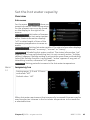
Get information
Overview
Sub-menus
INFO 3
For the menu INFO there are several
sub-menus. No settings can be made
in these menus, they just display information. Status information for the
relevant menu can be found on the
display to the right of the menus.
service info
service info shows temperature levels
and settings in the installation.
alarm log
compressor info shows operating
times, number of starts etc for the
compressor in the heat pump.
compressor info
runs
off
add. heat info
indoor temp. log
add. heat info displays information about the additional heat's operating
times etc.
alarm log displays the latest alarm and information about the heat pump
when the alarm occurred.
indoor temp. log the average temperature indoors week by week during
the past year.
Menu
3.1
service info
Information about the heat pump’s actual operating status (e.g. current
temperatures etc.) can be obtained here. No changes can be made.
The information is on several pages. Turn the control knob to scroll
between the pages.
Symbols in this menu:
48
Compressor
Heating
Addition
Hot water
Circulation pump, climate
system
Ventilation
Chapter 3 | F470 – at your service
NIBE™ F470
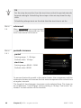
Menu
3.2
compressor info
Information about the compressor’s
operating status and statistics can be
obtained here. No changes can be
made.
The information is on several pages.
Turn the control knob to scroll
between the pages.
compressor info 3.2
status:
initiating
number of starts:
total operating time:
hrs
- of which hot water:
hrs
time factor:
- of which hot water:
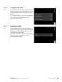
Menu
3.3
add. heat info
add. heat info3.3
Information about the additional
heat's settings, operating status and
statistics can be obtained here. No
changes can be made.
The information is on several pages.
Turn the control knob to scroll
between the pages.
Chapter 3 | F470 – at your service
status:
off
time factor:
NIBE™ F470
49
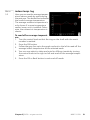
Menu
3.4
alarm log
alarm log 3.4
To facilitate fault-finding the heat
pump operating status at alarm alerts
is stored here. You can see information for the 10 most recent alarms.
TB alarm
LP alarm
Sensor flt:BT6
Sens flt:BT20
To view the run status in the event of
an alarm, mark the alarm and press
the OK button.
Sensor flt:BT2
Sensor flt:BT1
alarm log 3.4
Temperature limiter alarm(52)
outdoor temp.
-5.6 °C
heat medium flow
30.5 °C
heat medium return
25.0 °C
hot water charging
49.0 °C
condenser out
6.2 °C
operating time
30 min
op. mode
off
Information about an alarm.
50
Chapter 3 | F470 – at your service
NIBE™ F470
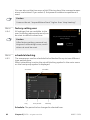
Menu
3.5
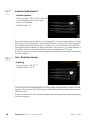
indoor temp. log
Here you can see the average temperature indoors week by week during
the past year. The dotted line indicates
the annual average temperature.
The average outdoor temperature is
only shown if a room temperature
sensor/room unit is installed. Otherwise, the exhaust air temperature is
shown.
indoor temp. log3.5
exhaust air °C
week
To read off an average temperature
1. Turn the control knob so that the ring on the shaft with the week
number is marked.
2. Press the OK button.
3. Follow the grey line up to the graph and out to the left to read off the
average indoor temperature at the selected week.
4. You can now select to take read outs for different weeks by turning
the control knob to the right or left and read off the average temperature.
5. Press the OK or Back button to exit read off mode.
Chapter 3 | F470 – at your service
NIBE™ F470
51
Adjust the heat pump
Overview
Sub-menus
For the menu HEAT PUMP there are
several sub-menus. Status information
for the relevant menu can be found
on the display to the right of the
menus.
plus functions Settings applying to
any installed extra functions in the
heating system.
op. mode Activation of manual or
automatic operating mode. The status
information shows the selected operating mode.
HEAT PUMP 4
plus functions
auto
op. mode
my icons
time & date
language / language
holiday setting
svenska
off
my icons Settings regarding which icons in the heat pump's user interface
that are to appear in the slot when the door is closed.
time & date Setting current time and date.
language Select the language for the display here. The status information
shows the selected language.
holiday setting Vacation scheduling heating, hot water and ventilation.
Status information "set" is displayed if you set a vacation schedule but it
is not active at the moment, "active" is displayed if any part of the vacation
schedule is active, otherwise it displays " off".
advanced Setting heat pump work mode.
Menu
4.1
plus functions
plus functions4.1
Settings for any additional functions
installed in F470 can be made in the
sub menus.
internet
sms
52
Chapter 3 | F470 – at your service
NIBE™ F470
Menu
4.1.3
internet
internet4.1.3
Here you make settings for connecting F470 to the internet.
NOTE
For these functions to work the
network cable must be connected.
Menu
4.1.3.1
nibe uplink
tcp/ip settings
proxy settings
nibe uplink
Here you can manage the installation's connection to NIBE Uplink™
(http://www.nibeuplink.com) and see
the number of users connected to the
installation via the internet.
A connected user has a user account
in NIBE Uplink™ which have been
given permission to control and/or
monitor your installation.
nibe uplink 4.1.3.1
serial number
connection string
number of users
request new connection string
switch off all users
Request new connection string
To connect a user account on NIBE Uplink™ to your installation, you must
request a unique connection string.
1. Mark “request new connection string" and press the OK button.
2. The installation now communicates with NIBE Uplink™ to create a
connection string.
3. When a connection string has been received, it is shown in this menu
at "connection string" and is valid for 60 minutes.
Disconnect all users
1. Mark “switch off all users" and press the OK button.
2. The installation now communicates with NIBE Uplink™ to release your
installation from all connected users via the internet.
NOTE
After disconnecting all users none of them can monitor or control your
installation via NIBE Uplink™ without requesting a new connection
string.
Chapter 3 | F470 – at your service
NIBE™ F470
53
Menu
4.1.3.8
tcp/ip settings
tcp/ip settings4.1.3.8
You can set TCP/IP settings for your
installation here.
Automatic setting (DHCP)
1. Tick “automatic". The installation
now receives the TCP/IP settings
using DHCP.
2. Mark “confirm" and press the OK
button.
automatic
ip-address
net mask
gateway
dns
confirm
reset
Manual setting
1.
2.
3.
4.
5.
6.
Untick "automatic", you now have access to several setting options.
Mark “ip-address" and press the OK button.
Enter the correct details via the virtual keypad.
Mark “OK" and press the OK button.
Repeat 1 - 3 for "net mask", "gateway" and "dns".
Mark “confirm" and press the OK button.
Caution
The installation cannot connect to the internet without the correct TCP/IP
settings. If unsure about applicable settings use the automatic mode or
contact your network administrator (or similar) for further information.
TIP
All settings made since opening the menu can be reset by marking "reset"
and pressing the OK button.
Menu
4.1.3.9
proxy settings
proxy settings 4.1.3.9
You can set proxy settings for your
installation here.
Proxy settings are used to give connection information to a intermediate
server (proxy server) between the installation and Internet. These settings
are primarily used when the installation connects to the Internet via a
company network. The installation
supports proxy authentication of the
HTTP Basic and HTTP Digest type.
use proxy
server
port
user name
password
confirm
reset
If unsure about applicable settings, contact your network administrator
(or similar) for further information.
54
Chapter 3 | F470 – at your service
NIBE™ F470
Setting
1.
2.
3.
4.
5.
6.
Tick “use proxy" if you do not want to use a proxy.
Mark “server" and press the OK button.
Enter the correct details via the virtual keypad.
Mark “OK" and press the OK button.
Repeat 1 - 3 for "port", "user name" and "password".
Mark “confirm" and press the OK button.
TIP
All settings made since opening the menu can be reset by marking "reset"
and pressing the OK button.
Menu
4.1.4
sms (accessory is required)
sms 4.1.4
Make settings for the accessory SMS
40 here.
Add the mobile numbers that are to
have access to change and receive
status information from the heat
pump. Mobile numbers must include
country code e.g. +46 XXXXXXXX.
phone number
alarm receiver
If you want to receive an SMS message in the event of the alarm mark
the box to the right of the telephone
number.
NOTE
Telephone numbers provided must be able to receive SMS messages.
Menu
4.1.5
SG Ready
SG Ready 4.1.5
This function can only be used in
mains networks that support the "SG
Ready"-standard .
Make settings for the function "SG
Ready" here.
Low price mode means that the electricity supplier has a low tariff and the
system uses this to reduce costs.
affect room temperature
affect hot water
Over capacity mode means that the
electricity supplier has set the tariff
very low and the system uses this to reduce the costs as much as possible.
Chapter 3 | F470 – at your service
NIBE™ F470
55
affect room temperature
Here you set whether room temperature should be affected when activating "SG Ready".
With low price mode of "SG Ready" the parallel offset of the indoor temperature is increased by "+1". If a room sensor is installed and activated,
the desired room temperature increases by 1 °C.
With over capacity mode of "SG Ready" the parallel offset for the indoor
temperature is increased by"+2". If a room sensor is installed and activated,
the desired room temperature increases by 2 °C.
affect hot water
Here you set whether the temperature of the hot water should be affected
when activating "SG Ready".
With low price mode on "SG Ready" the stop temperature of the hot water
is set as high as possible at only compressor operation (immersion heater
not permitted).
With over capacity mode of "SG Ready" the hot water is set to "luxury"
(immersion heater permitted).
NOTE
The function must be connected and activated in your F470.
56
Chapter 3 | F470 – at your service
NIBE™ F470
Menu
4.1.6
smart price adaption
smart price adaption 4.1.6
price of electricity overview
Here you can obtain information on
how the electricity price varies over
up to three days.
area
In this menu you state where the heat
pump is located and how great a role
the electricity price should play. The
greater the value, the greater the effect the electricity price has and the
possible savings are larger, but at the
same time there is an increased risk
of affecting comfort.
activated
price of electricity
overview
area
affect room temperature
affect hot water
affect room temperature
Setting range: 1 - 10
Factory setting: 5
affect hot water
Setting range: 1 - 4
Factory setting: 2
This function can only be used if you have an hourly tariff agreement with
your electricity supplier that supports Smart price adaption.
Smart price adaption moves the heat pump's consumption over 24 hours
to periods with the cheapest electricity tariff, which gives savings for hourly
rate based electricity contracts. The function is based on hourly rates for
the next 24 hours being retrieved via NIBE Uplink™ and therefore an internet connection and an account for NIBE Uplink™ are required.
Untick "activated" to switch off smart price adaption.
Chapter 3 | F470 – at your service
NIBE™ F470
57
Menu
4.2
op. mode
op. mode
op. mode 4.2
Setting range: auto, manual, add.
heat only
Default value: auto
auto
functions
manual
Setting range: compressor, addition, heating
add. heat only
The heat pump operating mode is usually set to "auto". It is also possible
to set the heat pump to "add. heat only", but only when an addition is
used, or "manual" and select yourself what functions are to be permitted.
Change the operating mode by marking the desired mode and pressing
the OK button. When an operating mode is selected, it shows what is
permitted in the heat pump (crossed out = not permitted) and selectable
alternatives to the right. To select selectable functions that are permitted
or not, mark the function using the control knob and press the OK button.
Operating mode auto
In this operating mode the heat pump automatically selects what functions
are permitted.
Operating mode manual
In this operating mode you can select what functions are permitted. You
cannot deselect "compressor" in manual mode.
Operating mode add. heat only
In this operating mode the compressor is not active, only additional heat
is used.
Caution
If you choose mode "add. heat only" the compressor is deselected and
there is a higher operating cost.
Functions
"compressor" is that which produces heating and hot water for the accommodation. If "compressor" is deselected, a symbol in the main menu
on the heat pump symbol is displayed. You cannot deselect "compressor"
in manual mode.
58
Chapter 3 | F470 – at your service
NIBE™ F470
"addition" is what helps the compressor to heat the accommodation
and/or the hot water when it cannot manage the whole requirement
alone.
"heating" means that you get heat in the accommodation. You can
deselect the function when you do not wish to have heating running.
Caution
If you deselect "addition" it may mean that insufficient hot water and/or
heating in the accommodation is achieved.
Menu
4.3
Menu
4.4
my icons
You can select what icons should be
visible when the door to F470 is
closed. You can select up to 3 icons. If
you select more, the ones you selected
first will disappear. The icons are displayed in the order you selected them.
my icons 4.3
outdoor/indoor temperature
hot water temperature
analog clock
digital clock
time & date
Set time and date, display mode and
time zone here.
TIP
Time and date are set automatically
if the heat pump is connected to
NIBE Uplink™. To obtain the correct
time, the time zone must be set.
Chapter 3 | F470 – at your service
time & date4.4
time
24 h
12 h
date
day
month
year
NIBE™ F470
59
Menu
4.6
language
Menu
4.7
holiday setting
language 4.6
Choose the language that you want
the information to be displayed in
here.
To reduce energy consumption during
a holiday you can schedule a reduction in heating, ventilation and hot
water temperature. Solar panel cooling can also be scheduled if the function is connected.
If a room sensor is installed and activated, the desired room temperature
(°C) is set during the time period. This
setting applies to all climate systems
with room sensors.
holiday setting4.7
activated
start date
stop date
heating
hot water comfort
ventilation
0
economy
normal
If a room sensor is not activated, the desired offset of the heating curve is
set. One step is usually enough to change the room temperature by one
degree, but in some cases several steps may be required. This setting applies
to all climate systems without room sensors.
Vacation scheduling starts at 00:00 on the start date and stops at 23:59
on the stop date.
TIP
Complete holiday setting about a day before your return so that room
temperature and hot water have time to regain usual levels.
TIP
Set the vacation setting in advance and activate just before departure
in order to maintain the comfort.
60
Chapter 3 | F470 – at your service
NIBE™ F470
Caution
If you choose to switch off hot water production during the vacation
“periodic increase" (preventing bacterial growth) are blocked during
this time. "periodic increase" started in conjunction with the vacation
setting being completed.
Caution
If the exhaust air temperature falls below 16 °C, the compressor is
blocked and the electrical addition is permitted to intervene. When the
compressor is blocked heat is not recovered from the exhaust air.
Menu
4.9
advanced
advanced 4.9
Menu advanced has orange text and
is intended for the advanced user. This
menu has several sub-menus.
auto mode setting
factory setting user
schedule blocking
Menu
4.9.2
off
auto mode setting
stop heating
auto mode setting4.9.2
Setting range: -20 – 40 °C
Default values: 20
stop heating
°C
Setting range: -25 – 40 °C
stop additional heat
°C
Factory setting: 15
filtering time
hrs
stop additional heat
filtering time
Setting range: 0 – 48 h
Default value: 24 h
When the operating mode is set to "auto", the heat pump selects when
start and stop of additional heat and heat production is permitted, dependent on the average outdoor temperature.
Select the average outdoor temperatures in this menu.
Chapter 3 | F470 – at your service
NIBE™ F470
61
You can also set the time over which (filtering time) the average temperature is calculated. If you select 0, the present outdoor temperature is
used.
Caution
It cannot be set "stop additional heat" higher than "stop heating".
Menu
4.9.4
factory setting user
factory setting user 4.9.4
All settings that are available to the
user (including advanced menus) can
be reset to default values here.
Do you want to reset all user settings to
factory settings?
Caution
After factory setting, personal settings such as heating curves, ventilation etc must be reset.
Menu
4.9.5
no
yes
schedule blocking
The compressor can be scheduled to be blocked for up to two different
time periods here.
When scheduling is active the actual blocking symbol in the main menu
on the heat pump symbol is displayed.
Schedule
Activated
schedule blocking 4.9.5
schedule 1
schedule 2
activated
all
mon
tues
we
thur
fri
sat
sun
Conflict
Day
Time period
Blocking
Schedule: The period to be changed is selected here.
62
Chapter 3 | F470 – at your service
NIBE™ F470
Activated: Scheduling for the selected period is activated here. Set times
are not affected at deactivation.
Day: Select which day or days of the week the schedule is to apply to here.
To remove the scheduling for a particular day, the time for that day must
be reset by setting the start time to the same as the stop time. If the line
"all" is used, all days in the period are set for these times.
Time period: The start and stop time for the selected day for scheduling
are selected here.
Blocking: The desired blocking is selected here.
Conflict: If two settings conflict with each other a red exclamation mark
is displayed.
Blocking the compressor.
Blocking additional heat.
TIP
If you wish to set similar scheduling for every day of the week start by
filling in “all” and then changing the desired days.
TIP
Set the stop time earlier than the start time so that the period extends
beyond midnight. Scheduling then stops at the set stop time the day
after.
Scheduling always starts on the date that the start time is set for.
Caution
Long term blocking can cause reduced comfort and operating economy.
Chapter 3 | F470 – at your service
NIBE™ F470
63
4 Disturbances in comfort
In most cases, the heat pump notes operational interference (operational
interference can lead to disturbance in comfort) and indicates this with
alarms and shows action instructions in the display.
Info menu
All the heat pump measurement values are gathered under menu 3.1 in
the heat pump menu system. Looking through the values in this menu
can often simplify finding the fault source. See page 48 for more information about menu 3.1.
Manage alarm
In the event of an alarm, some kind of
malfunction has occurred, which is
indicated by the status lamp changing
from green continuously to red continuously. In addition, an alarm bell
appears in the information window.
Low pressure alarm
alarm
info / action
Alarm
reset alarm
aid mode
In the event of an alarm with a red
status lamp a malfunction has occurred that the heat pump cannot
remedy itself. In the display, by turning the control knob and pressing the OK button, you can see the type of
alarm it is and reset it. You can also choose to set the heat pump to aid
mode.
info / action Here you can read what the alarm means and receive tips
on what you can do to correct the problem that caused the alarm.
reset alarm In most cases it is enough to select "reset alarm" to correct
the problem that caused the alarm. If a green light illuminates after selecting "reset alarm" the alarm has been remedied. If a red light is still visible
and a menu called ”alarm” is visible in the display, the problem that caused
the alarm remains. If the alarm disappears and then returns, contact your
installer.
aid mode ”aid mode” is a type of emergency mode. This means that the
heat pump produces heat and/or hot water despite there being some
kind of problem. This can mean that the heat pump's compressor is not
running. In this case the immersion heater produces heat and/or hot water.
64
Chapter 4 | Disturbances in comfort
NIBE™ F470
NOTE
To select aid mode an alarm action must be selected in the menu 5.1.4.
Caution
Selecting "aid mode” is not the same as correcting the problem that
caused the alarm. The status lamp will therefore continue to be red.
If the alarm does not reset, contact your installer for suitable remedial action.
NOTE
Always give the product's serial number (14 digits) when reporting a
fault.
Troubleshooting
If the operational interference is not shown in the display the following
tips can be used:
Basic actions
Start by checking the following possible fault sources:
■ The switch's position.
■ Group and main fuses of the accommodation.
■ The property's earth circuit breaker.
Low hot water temperature or a lack of hot water
■ Closed or choked filling valve for the hot water heater.
■ Open the valve.
■ Heat pump in incorrect operating mode.
■ Enter menu 4.2. If mode "auto" is selected, select a higher value on
"stop additional heat" in menu 4.9.2.
■ If mode "manual" is selected, select "addition".
■ Large hot water consumption.
■ Wait until the hot water has heated up. Temporarily increased hot
water capacity (temporary lux) can be activated in menu 2.1.
■ Too low hot water setting.
■ Enter menu 2.2 and select a higher comfort mode.
■ Filter blocked.
■ Clean or replace filter (see page 21).
Chapter 4 | Disturbances in comfort
NIBE™ F470
65
Low room temperature
■ Closed thermostats in several rooms.
■ See section "Saving tips" on page 25 and menu 1.1 on page 28 for
more detailed information about how to best set the thermostats.
■ Heat pump in incorrect operating mode.
■ Enter menu 4.2. If mode "auto" is selected, select a higher value on
"stop heating" in menu 4.9.2.
■ If mode "manual" is selected, select "heating". If this is not enough,
select "addition".
■ Too low set value on the automatic heating control.
■ Enter menu 1.1 "temperature" and adjust the offset heating curve up.
■
■
■
■
■
■
If the room temperature is only low in cold weather the curve slope
in menu 1.9.1 "heating curve" needs adjusting up.
"comfort mode" "luxury" selected in combination with large hot water
outlet.
■ Enter menu 2.2 and select "economy" or "normal".
"Holiday mode" activated in menu 4.7.
■ Enter menu 4.7 and select "Off".
External switch for changing the room heating activated.
■ Check any external switches.
Air in the heating system.
■ Vent the heating system.
Closed valves to the heating system.
■ Open the valves (contact your installer for assistance in finding them).
Filter blocked.
■ Clean or replace filter (see page 21).
High room temperature
■ Too high set value on the automatic heating control.
■ Enter menu 1.1 (temperature) and reduce the offset heating curve. If
the room temperature is only high in cold weather the curve slope in
menu 1.9.1 "heating curve" needs adjusting down.
■ External switch for changing the room heating activated.
■ Check any external switches.
Low system pressure
■ Not enough water in the heating system.
■ Top up the water in the heating system.
Low or a lack of ventilation
■ The ventilation is not adjusted.
66
Chapter 4 | Disturbances in comfort
NIBE™ F470
■ Order ventilation adjustment.
■ Filter blocked.
■ Clean or replace filter (see page 21).
■ Exhaust air device blocked or throttled down too much.
■ Check and clean the exhaust air devices (see page 20).
■ Fan speed in reduced mode.
■ Enter menu 1.2 and select "normal".
■ External switch for changing the fan speed activated.
■ Check any external switches.
High or distracting ventilation
■ The ventilation is not adjusted.
■ Order ventilation adjustment.
■ Fan speed in forced mode.
■ Enter menu 1.2 and select "normal".
■ External switch for changing the fan speed activated.
■ Check any external switches.
■ Filter blocked.
■ Clean or replace filter (see page 21).
Low supply air temperature
■ Air in the supply air battery
■ Bleed the supply air battery.
■ Trim valve too restricted
■ Contact your installer!
High supply air temperature
■ Trim valve not sufficiently restricted.
■ Contact your installer!
The compressor does not start
■ There is no heating requirement.
■ The heat pump does not call on heating nor hot water.
■ The heat pump defrosts.
■ Temperature conditions tripped.
■ Wait until the temperature condition has been reset.
■ Minimum time between compressor starts has not been reached.
■ Wait 30 minutes and check if the compressor has started.
■ Alarm tripped.
■ Follow the display instructions.
Chapter 4 | Disturbances in comfort
NIBE™ F470
67
5 Technical data
Detailed technical specifications for this product can be found in the installation manual (www.nibe.eu).
68
Chapter 5 | Technical data
NIBE™ F470
6 Glossary
Additional heat
The additional heat is the heat produced in addition to the heat supplied
by the compressor in your heat pump. Additional heaters can be for example, immersion heater, electric heater, gas/oil/pellet/wood burner or
district heating.
Calculated flow line temperature
The temperature that the heat pump calculates that the heating system
requires for an optimum accommodation temperature. The colder the
outdoor temperature, the higher the calculated supply temperature.
Circulation pump
Pump that circulates liquid in a pipe system.
Climate system
The climate system can also be called the heating and/or cooling system.
The building is cooled or heated using radiators, under floor coils or convector fans.
Compressor
Compresses the gas state refrigerant. When the refrigerant is compressed,
the pressure and the temperature increase.
Condenser
Heat exchanger where the hot gas state refrigerant condenses (cooled
and becomes a liquid) and releases heat energy to the house heating and
hot water systems.
Disturbances in comfort
Disturbances in comfort are undesirable changes to the hot water/indoor
comfort, for example when the temperature of the hot water is too low
or if the indoor temperature is not at the desired level.
A malfunction in the heat pump can sometimes be noticed in the form of
a disturbance in comfort.
In most cases, the heat pump notes operational interference and indicates
this with alarms and shows instructions in the display.
Domestic hot water
The water one showers in for example.
Chapter 6 | Glossary
NIBE™ F470
69
Electrical addition
This is the electricity that, for example, an immersion heater produces
when the compressor's output is not sufficient to fulfil the property's
heating demand.
Emergency mode
A mode that can be selected using the switch in the event of a fault, which
means that the compressor stops. When the heat pump is in emergency
mode, the building and/or hot water is heated using an immersion heater.
Evaporator
Heat exchanger where the refrigerant evaporates by retrieving heat energy
from the air which then cools.
Exhaust air
The air that comes from the exhaust air device in the various rooms of the
accommodation, to F470.
Exhaust air devices
Vents, usually in the ceiling, in the kitchen/bathroom/clothes closet where
the air is drawn in to be forwarded to F470.
Expansion valve
Valve that reduces the pressure of the refrigerant, whereupon the temperature of the refrigerant drops.
Expansion vessel
Vessel with heating medium fluid with the task of equalising the pressure
in the heating medium system.
Extract air
The air that the heat pump has retrieved heat from and which has therefore
been cooled. This air is blown out of the building.
Filtering time
Indicates the time the average outdoor temperature is calculated on.
Flow pipe
The line in which the heated water is transported from the heat pump out
to the house heating system (radiators/heating coils).
70
Chapter 6 | Glossary
NIBE™ F470
Heat exchanger
Device that transfers heat energy from one medium to another without
mixing mediums. Examples of different heat exchangers are evaporators
and condensers.
Heat factor
Measurement of how much heat energy the heat pump gives off in relation
to the electric energy it needs to operate. Another term for this is COP.
Heating curve
The heating curve determines which heat the heat pump is to produce
depending on the temperature outdoors. If a high value is selected, this
tells the heat pump that it must produce a lot of heat when it is cold outdoors in order to achieve a warm indoor temperature.
Heating medium
Hot liquid, usually normal water, which is sent from the heat pump to the
house climate system and makes the accommodation warm. The heating
medium also heats the hot water.
Heating medium side
Pipes to the house’s climate system make up the heating medium side.
Mixing valve
A valve that mixes the cold water with the hot water leaving the heater.
Outdoor air
Air that is drawn into the heat pump and heated.
Outside sensor
A sensor that is located outdoors. This sensor tells the heat pump how hot
it is outdoors.
Pressostat
Pressure switch that triggers an alarm and/or stops the compressor if nonpermitted pressures occur in the system. A high pressure pressostat trips
if the condensing pressure is too great. A low pressure pressostat trips if
the evaporation pressure is too low.
Radiator
Another word for heating element. They must be filled with water in order
to be used with F470.
Chapter 6 | Glossary
NIBE™ F470
71
Refrigerant
Substance that circulates around a closed circuit in the heat pump and
that, through pressure changes, evaporates and condenses. During evaporation, the refrigerant absorbs heating energy and when condensing
gives off heating energy.
Return pipe
The line in which the water is transported back to the heat pump from
the house heating system (radiators/heating coils).
Return temp
The temperature of the water that returns to the heat pump after releasing
the heat energy to the radiators/heating coils.
Room sensor
A sensor that is located indoors. This sensor tells the heat pump how hot
it is indoors.
Safety valve
A valve that opens and releases a small amount of liquid if the pressure is
too high.
Shunt
A valve that mixes the hot water with a small amount of slightly cooler
water. There is a shunt in the heat pump that mixes the supply water with
the return line water so that the heating system reaches the correct temperature.
Supply air
The heated air that is blown from the heat pump and out into the room.
Supply air device
Valves, usually in the ceiling, where the heated supply air is blown out and
aids in heating up the accommodation.
Supply temperature
The temperature of the heated water that the heat pump sends out to
the heating system. The colder the outdoor temperature, the higher the
supply line temperature becomes.
Water heater
Container where domestic water is heated. Is located inside the heat pump,
but an extra hot water heater can be installed in the event of large hot
water requirements.
72
Chapter 6 | Glossary
NIBE™ F470
7 Item register
A
Adjust the heat pump, 52
Alarm, 64
B
Back button, 12
C
Contact with F470, 10
Display unit, 11
External information, 10
Menu system, 13
Control knob, 12
D
Display, 11
Display unit, 11
Back button, 12
Control knob, 12
Display, 11
OK button, 12
Status lamp, 11
Switch, 12
Disturbances in comfort, 64
Alarm, 64
Manage alarm, 64
Troubleshooting, 65
E
External information, 10
Information window, 10
Status lamp, 10
F
F470 – An excellent choice, 7
F470 – at your service, 28
Adjust the heat pump, 52
Get information, 48
Set the hot water capacity, 43
Set the indoor climate, 28
G
Get information, 48
Glossary, 69
H
Heat pump function, 9
Help menu, 19
Chapter 7 | Item register
I
Important information, 2
F470 – An excellent choice, 7
Installation data, 2
Serial number, 5
Warranty information, 5
Information window, 10
Installation data, 2
M
Maintenance of F470, 20
Regular checks, 20
Saving tips, 25
Manage alarm, 64
Menu system, 13
Help menu, 19
Operation, 15
Scroll through the windows, 19
Selecting menu, 15
Selecting options, 16
Setting a value, 17
Use the virtual keyboard, 18
O
OK button, 12
Operation, 15
P
Power consumption, 26
R
Regular checks, 20
S
Saving tips, 25
Power consumption, 26
Scroll through the windows, 19
Selecting menu, 15
Selecting options, 16
Serial number, 5
Set the hot water capacity, 43
Set the indoor climate, 28
Setting a value, 17
Status lamp, 10–11
Switch, 12
T
Technical data, 68
NIBE™ F470
73
The heat pump – the heart of the
house, 8
Troubleshooting, 65
U
Use the virtual keyboard, 18
W
Warranty information, 5
74
Chapter 7 | Item register
NIBE™ F470
WS name: -Gemensamt
WS version: a77 (working edition)
Publish date: 2015-09-09 11:24
NIBE Energy Systems Ltd
3C Broom Business Park
Bridge Way
Chesterfield S41 9QG
Phone 0845 095 1200
Fax 0845 095 1201
[email protected]
www.nibe.co.uk
231495