1
User
Manual
ProScale
Series 950
Warranty
Mitutoyo America Corporation Inc., (MAC) warrants this product against defective parts
and workmanship for one year, commencing from the date of original purchase. Upon
notification of a defect, MAC shall have the option to repair or replace any defective part.
Such services shall be the customer's sole and exclusive remedy. Expenses incidental to
repair, maintenance, or replacement under warranty, including those for labor and
material, shall be borne by MAC. Freight or transportation charges to MTI shall be paid
by the customer.
Except as expressly provided in this warranty, MAC., does not make any warranties in
respect to the product, either expressed or implied, including implied warranties of
merchantability or fitness for a particular purpose, except as expressly provided in this
agreement.
MAC shall not be liable for any special, incidental, or consequential damages or for loss,
damage or expense directly or indirectly arising from the customer's use of or inability to
use the equipment either separately or in combination with other equipment, or for
personal injury or loss or destruction of other property, or from any other cause.
SAFETY WARNING
Before installing ProScale products, turn off the
machine and disconnect it from its power source to
avoid injury.
SAFETY WARNING
Revision B, P/N 800-1024-002. Copyright
2002, All rights reserved.
Mitutoyo America Corp. - ProScale Series 950 DRO
2 of 35
Table of Contents
SECTION 1
GENERAL INFORMATION ........................................................................................................................4
Introduction ............................................................................................................................................................4
ProScale Terminology ...........................................................................................................................................4
Scales ....................................................................................................................................................................5
Readheads ............................................................................................................................................................6
Displays .................................................................................................................................................................7
Replacement Parts ................................................................................................................................................7
Product Specifications ...........................................................................................................................................8
SECTION 2
950- 404 AND 950-405 .........................................................................................................................9
Installation:.............................................................................................................................................................9
Calibration:...........................................................................................................................................................10
Calibration:...........................................................................................................................................................11
Maintenance: .......................................................................................................................................................11
SECTION 3
950- 406 AND 950-407 .......................................................................................................................12
Installation:...........................................................................................................................................................12
Calibration:...........................................................................................................................................................15
Maintenance: .......................................................................................................................................................15
SECTION 4
DIGITAL D ISPLAY ...............................................................................................................................16
Display Power ..................................................................................................................................................16
Programming The Display................................................................................................................................16
Position Display Units ......................................................................................................................................18
Measuring Modes.............................................................................................................................................18
Offset Adjustment.............................................................................................................................................19
Lock Mode........................................................................................................................................................19
Display Hold Mode ...........................................................................................................................................19
Position Monitor Mode .....................................................................................................................................20
Segment Offset Adjustment .............................................................................................................................20
Sending position to SPC device.......................................................................................................................21
Jumpers ............................................................................................................................................................21
Changing the Batteries.....................................................................................................................................22
Mounting the Display........................................................................................................................................22
SECTION 5
M ISCELLANEOUS ................................................................................................................................23
Scales ...............................................................................................................................................................23
Readheads .......................................................................................................................................................23
Frequently Asked Questions ............................................................................................................................24
Error Codes & Factory Service ........................................................................................................................25
Communicating With Other Equipment ...........................................................................................................25
Read Head Output ...........................................................................................................................................25
Abbe Error ........................................................................................................................................................27
Appendix A .......................................................................................................................................................28
SECTION 6
ACCESSORIES ....................................................................................................................................31
ProMUX-3 ............................................................................................................................................................31
ProMUX-4, ProMUX-8.........................................................................................................................................32
Pro RF..................................................................................................................................................................33
Mitutoyo America Corp. - ProScale Series 950 DRO
3 of 35
SECTION 1
GENERAL INFORMATION
Introduction
ProScale digital measuring systems are affordable precision electronic devices for
making linear measurements with speed and accuracy. ProScale consists of a scale, a
readhead (or encoder) and a digital display. It uses capacitive encoder technology, the
same technology used in digital calipers.
ProScale is ideal for most measuring requirements where high – (<10 m) – accuracy is
not needed. Because ProScale shows the exact measurement on its display, it
eliminates the guesswork involved in reading and interpreting tape, pointer, or shaft
encoder scales. It is compatible for retrofitting or as original equipment on most
machinery and as a result, machine setup time can be reduced considerably, maximizing
throughput on a machine.
ProScale's measurement mode can be changed to display sixteenths, thirty-seconds,
sixty-fourths, or thousandths of an inch; millimeters or centimeters. In any mode,
ProScale is designed to provide and maintain its accuracy for years.
ProScale is extremely rugged and durable. Unlike optical measurement systems, the
accuracy of capacitive systems is not affected by sawdust or other non-conductive
contaminants. Additionally, power consumption is much less than magnetic or optical
measurement systems.
Because ProScale is a solid-state electronic device there's very little to wear out. The
readhead and scale are designed to withstand shop dirt, dust, and other airborne
contaminants, and the controls are sealed with a protective cover for long life. With
normal care, ProScale will last for years.
ProScale Terminology
All ProScale systems consist of a SCALE, a READHEAD, and a digital DISPLAY.
The SCALE consists of a series of conductive patterns bonded to an aluminum extrusion.
The READHEAD contains a computer chip, which transmits and receives signals to the
scale using capacitive coupling. The received signal is used by the readhead to calculate
it’s position to within 0.005mm. This position data is then sent to the digital DISPLAY,
where it can be displayed in millimeters, centimeters, inches, or sent to an external data
acquisition device.
Absolute technology systems use a robust and sophisticated method to measure
position, resulting in a high immunity to electrical interference and one that does not
forget its position when power is removed.
Mitutoyo America Corp. - ProScale Series 950 DRO
4 of 35
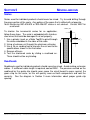
Scales
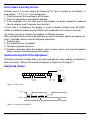
An absolute, (ABS), system measures its actual position by reading a pattern which is
unique at any given location over its length. The maximum length of a ProScale absolute
pattern is 430mm (16.932 in.). The pattern must then repeat itself.
Consider the illustration above to represent a ProScale ABS. There are three absolute
patterns (each pattern is 430mm long), joined together end to end. Within each pattern
the system is totally absolute. However, crossing over a pattern joint now presents the
readhead with information identical to what it read in the previous pattern. At this point
the system must be able to recognize that it has crossed over a pattern joint and
therefore must add or subtract the value of 1 pattern offset - 430mm. In fact, each time
the readhead passes over a pattern joint it must keep track of how many patterns it has
passed, and in which direction. This action is accomplished by the digital display.
What does all this mean? If the readhead remains on the same absolute pattern, it can
have power removed, its position changed and power restored without loss of position
information. However, if power is removed and the readhead passes over a pattern joint,
the transition will not be recognized. When power is restored the system knows its
absolute position on the new pattern, but does not know how many patterns it has
passed, or in which direction!
ProScale displays provide the operator with a method to adjust the pattern offset so the
system displays the correct reading at all times without loss of accuracy. See Section 4
All ABS scales have a “zigzag” pattern etched onto the green laminate. Take care to not
damage this etching or remove the green coating. There should also be a pattern
“break” approximately every 430mm (17in.). Do not attempt to shorten ABS style
scales; call Accurate Technology 800-233-0580 for assistance.
All 950-404 & 405 Series scales should be mounted to machinery using the supplied M5
(or 10-32) machine screw and Connector Link. This Connector Link is specially designed
to flex slightly if there is any mechanical binding in the readhead-to-scale mounting.
The Connector Link should always be mounted in the same direction as the scale (see
the diagram Section 2). Warranty is void if the Connector Link is not used.
All 950-406 & 407 scales are designed to be mounted on machinery using M4 (or 6-32)
Flathead screws. MAC provides a Guide Clip to attach the readhead to a moving part of
a machine, see the diagram in Section 3 Warranty is void if the Guide Clip is not used.
Mitutoyo America Corp. - ProScale Series 950 DRO
5 of 35
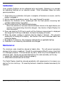
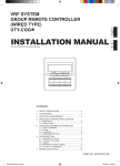
Readheads
ABS readheads have “BLACK END OF SCALE” labels on the cover, and the wire exits
from the corner of the housing. Extreme care must be taken not to damage the six brass
“fingers” inside the readhead housing. ABS style readheads, used in all 950 Series
systems, must be mounted on ABS scales with a particular orientation. Each readhead
has an arrow on the label pointing in the direction of the “BLACK END OF SCALE”
(each ABS style scale will have one end painted black). This relationship is very
important, since the readhead will work, but produce erratic results if incorrectly installed.
To insure proper operation, be sure the arrow on the readhead is pointing toward the
BLACK end of the scale. The standard readhead has 2m (10 ft.) of cable. For special
cable lengths, contact MAC.
ABS Readhead
ABS Style Pattern
ABS Scale
Mitutoyo America Corp. - ProScale Series 950 DRO
6 of 35
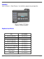
Displays
Refer to Section 4 - Digital Displays - for installation, programming and operation.
General Purpose LCD Display
(Replaces all previous displays)
Replacement Parts
Part
Part Number
950-404 Scale only
700-1510-001
950-405 Scale only
700-1518-001
950-406 Scale only
700-2504-001
950-407 Scale only
700-2508-001
950-404 & 405 Flex link
100-1025-001
950-406 & 407 Guide clip
100-1026-001
Instruction Manual
800-1024-002
Digital Display
701-1006-001
Read head
701-1003-001
Mitutoyo America Corp. - ProScale Series 950 DRO
7 of 35
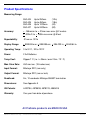
Product Specifications
Measuring Range:
950-404
950-405
950-406
950-407
Up
Up
Up
Up
to 250mm
to 450mm
to 1200mm
to 2400mm
(10in)
(18in)
(4ft)
(8ft)
Accuracy:
+ .165mm/m to + .20mm max error @ 2 meters
+ .002in/ft to + .008in max error @ 8 feet
Repeatability:
.01mm or .001in
Display Range:
+ 9999.99 mm; + 999.999 cm; + 394.000 in; + 99 63/64 in.
Operating Temp:
0 to 51°C, 32 to 120°F
Power:
2 AA Batteries
Temp Coef:
25ppm/1°C (i.e. ∆ .06mm / over 2.5m / 10° C)
Max. Slew Rate:
450 mm/sec. (18 inches/sec.)
Input Format:
Mitutoyo SPC (mm only)
Output Format:
Mitutoyo SPC (mm or inch)
Readhead:
2m, 10-conductor Mitutoyo 936937 termination
Dimensions:
See Appendix A
US Patents:
4420754, 4879508, 4878013, 4959615
Warranty:
One year from date of purchase.
All ProScale products are MADE IN USA
Mitutoyo America Corp. - ProScale Series 950 DRO
8 of 35
SECTION 2
950- 404 AND 950-405
ProScale 950- 404 and 950-405
General Purpose system with standard measuring ranges of 250mm and 450mm.
950-404/405 systems use ABS style scales, ABS style readheads, and general-purpose
digital displays. Neither the scale nor readhead are compatible with other MAC ProScale
incremental systems.
ProScale is easy to install. By following the basics of good installation in this section,
reliable, error-free operation is assured. Because ProScale can be installed on many
different types and brands of equipment, all installations will be a little different.
Therefore, it's the responsibility of the installer to choose the bolts, screws, or other
mounting hardware that guarantee proper installation for optimum operation.
Installation:
1. Note the orientation of the readhead on the scale. Be sure the arrow on the readhead
points towards the “BLACK END OF SCALE”. This orientation is critical for proper
operation of ProScale. Be sure the mounting location for the readhead and scale will
allow this orientation.
2. Determine an appropriate mounting location for the system. The readhead should be
mounted to a stationary part of the machine. The scale should be mounted to the
moving part of the machine with the connector link. Be sure to allow sufficient space
to accommodate the connector link, which is used to mount the scale to the moving
part of the machine. The Display should be mounted in a location which allows for
easy viewing by the machine operator. The location of the parts should also
safeguard the cable from possible damage. All ProScale wiring should be kept as far
away as possible from the machine’s wiring and motors and dust collection systems.
Avoid running the readhead wiring parallel to high voltage/current wiring.
Mitutoyo America Corp. - ProScale Series 950 DRO
9 of 35
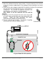
3. Mount the readhead using three screws or bolts. It may be necessary to use washers
or spacers to ensure a good mount (if the readhead is to be mounted on an uneven
surface).
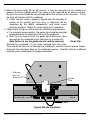
4. Check that the scale is properly aligned with the direction of motion of the moving part.
The connector link will compensate for only a small amount of
misalignment. The connector link must be mounted in the
same direction as the scale (as in the figure below).
Note: Failure to use the connector link will void the
warranty.
5. Mount one end of the connector link to the scale using an M5
(or 10-32) screw and the other end to the moving part of the
machine.
Check that both connections are secure;
inaccurate/erratic readings may otherwise occur.
6. Plug the readhead into the display. See Section 4 regarding
mounting and use of different display versions.
Connector Link
DISPLAY
CONNECTOR LINK
READHEAD
MOVEMENT
MOVING PART OF MACHINE
A Typical Model 950-404 Installation
Mitutoyo America Corp. - ProScale Series 950 DRO
10 of 35
Calibration:
Once installed, ProScale can be calibrated easily and quickly. Following is an example
for calibrating ProScale on an industrial sander. Other installations follow the same
general procedure.
1. Check to be sure installation of all parts is complete, all fasteners are secure, and the
display is plugged in.
2. Set the machine to operate as normal. Run a part through the sander.
3. Measure the thickness of the sanded part with the most precise measuring tool
available (digital calipers if possible).
4. Press the zero key on the ProScale digital display.
Note: If the direction of movement and the direction shown on the digital display are
opposite, the programming should be changed. See Section 4 Digital Displays for
more information.
5. Press and hold the PLUS key to scroll until the thickness measurement is displayed
(the longer the PLUS key is held down, the faster the display will scroll).
6. When the proper reading is reached, lock the display if desired. This prevents
accidentally re-zeroing of the display. See Section 4 for more information about how
to lock the display.
7. Re-calibrate, if necessary, after changing sanding belts (or applicable tooling).
8. Calibration is not necessary after batteries are changed.
Maintenance:
The aluminum scale should be cleaned of debris often. This will prevent premature
damage to the scale or readhead. Should the scale become difficult to move, check that
it is thoroughly cleaned. Find and remove any burrs, which may have developed on the
aluminum scale. Do not use any liquid lubricants on the scale assembly, as this may:
1. Impede the readhead's ability to operate properly.
2. Attract other contaminants to the scale.
The Digital Display should be cleaned periodically with compressed air to remove any
dust on the lens and keys. All mounting fasteners should be checked occasionally for
tightness.
Mitutoyo America Corp. - ProScale Series 950 DRO
11 of 35
SECTION 3
950- 406 AND 950-407
ProScale 950-406 and 407
General Purpose system with standard measuring ranges of 1.2m and 2.4m.
950-406/407 systems use ABS style scales, ABS style readheads, and general-purpose
digital displays. Neither the scale nor readhead are compatible with other MAC ProScale
incremental systems
ProScale is easy to install. By following the basics of good installation in this section,
reliable, error-free operation is assured. Because ProScale can be installed on many
different types and brands of equipment, all installations will be a little different, therefore
it's the responsibility of the installer to choose the bolts, screws, or other mounting
hardware that guarantee proper installation for optimum operation.
Installation:
1. Note the orientation of the readhead on the scale. Be sure the arrow on the readhead
points towards the “BLACK END OF SCALE”. This orientation is critical for proper
operation of ProScale. Check to be sure the mounting location for the system will
allow this orientation.
2. Determine an appropriate mounting location for the system. The scale should be
mounted to a stationary part of the machine. The readhead slides along the scale,
using the supplied guide clip to transfer machine movement to readhead movement.
The Display should be mounted in a location which allows for easy viewing by the
machine operator. The location of the parts should also safeguard the cable from
possible damage. All ProScale wiring should be kept as far away as possible from the
machine’s wiring and motors. Avoid running the readhead wiring parallel to high
voltage/current wiring or dust collection systems.
Mitutoyo America Corp. - ProScale Series 950 DRO
12 of 35
3. Mount the scale using M4 (or #6) screws. It may be necessary to use washers or
spacers to ensure a good mount if the scale is to be mounted on an uneven surface.
Be sure the screw heads do not protrude above the surface of the extrusion. If they
do, they will interfere with the readhead.
a. Check that the scale is properly aligned with the direction of
motion of the moving part (any error in alignment will be
magnified by the digital components, and could cause
premature failure). Adjust the scale alignment if necessary.
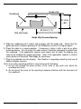
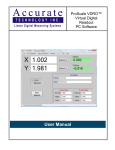
4. Referring to the figure, note these two installation requirements:
a. For accurate measurements, the guide clip should be mounted
perpendicular to the direction of travel of the readhead.
b. Over the full range of travel, the guide clip should exert some
pressure on the readhead so the two move as a single unit.
Guide Clip
Note:Failure to use the guide clip will void the warranty.
Reinstall the readhead if it has been removed from the scale.
Care should be taken to not damage the readhead’s sensitive internal ground fingers.
Also note the orientation label on the readhead housing. Carefully slide the readhead
onto the scale, checking for the proper orientation.
M ov ing
p a rt of
m a chin e
G u id e
C lip
R e a d he a d
S c a le
C a b le
Typical 950-406 Installation
Mitutoyo America Corp. - ProScale Series 950 DRO
13 of 35
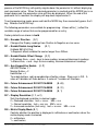
Guide Clip
Readhead
21.2mm
(.83")
33.0mm (1.3")
950-406 Scale
Guide Clip Pressure/Spacing
5. Slide the readhead until it meets and engages with the guide clip. Check that the
guide clip exerts sufficient pressure on the readhead, as seen in the figure above.
6. Place the cable in a secure position. If necessary, fasten it with a wire tie or other
fastening device. Do not leave the cable where it could be damaged or pulled from
the readhead. If the application requires over twenty feet of cable, the display may
need to be modified for proper operation. Also, if the application requires a shorter
scale, please call Accurate Technology for assistance.
7. Plug the readhead into the display. See Section 4 regarding mounting and use of
different display versions.
Note: If any other mounting method is used, observe the following:
a. Do not drill through the green portion of the scale at any point over which the
readhead will travel.
b. Do not mount the scale so the mounting hardware interferes with the movement of
the readhead.
Mitutoyo America Corp. - ProScale Series 950 DRO
14 of 35
Calibration:
Once installed, ProScale can be calibrated easily and quickly. Following is an example
for calibrating ProScale on a table saw fence. Other installations follow the same general
procedure.
1. Check to be sure installation of all parts is complete, all fasteners are secure, and the
display is plugged in.
2. Cut a part using the normal fence operation.
3. Measure the length of the part with the most precise measuring tool available (i.e.
digital calipers).
4. Press the zero key on the ProScale digital display.
Note: If the direction of movement and the direction shown on the digital display are
opposite, the programming should be changed. See Section 4 Digital Displays for
more information.
5. Press and hold the PLUS key to scroll until the length measurement is displayed (the
longer the PLUS key is held down, the faster the display will scroll).
6. When the proper reading is reached, lock the display if desired. This prevents
accidentally re-zeroing of the display. See Section 4 for more information about how
to lock the display.
7. Re-calibrate, if necessary, after changing saw blades (or applicable tooling).
8. Calibration is not necessary after batteries are changed.
Maintenance:
The aluminum scale should be cleaned of debris often. This will prevent premature
damage to the scale or readhead. Should the readhead assembly become difficult to
move, check that the scale is thoroughly cleaned. Find and remove any burrs, which
may have developed on the aluminum scale. Do not use any liquid lubricants on the
scale assembly, as this may:
1. Impede the readhead's ability to operate properly.
2. Attract other contaminants to the scale.
The Digital Display should be cleaned periodically with compressed air to remove any
dust on the lens and keys. All mounting fasteners should occasionally be checked for
tightness. If there is any wear on the green laminate of the scale, the guide clip pressure
on the readhead should be reduced. If wear continues, the readhead bearing should be
replaced. Call Mitutoyo America for assistance.
Mitutoyo America Corp. - ProScale Series 950 DRO
15 of 35
SECTION 4
DIGITAL DISPLAY
Display Power
Momentarily pressing the On/Off key will cause the unit to turn the display on or off.
While on, if no key presses or positional changes occur for more than 15 minutes, the
ProScale will automatically turn itself off to conserve battery life. While off, if a position
change is detected or the On/Off button is pressed, the display will automatically turn
itself on.
Programming The Display
To customize the General Purpose Digital Display, several functions of the display are
user programmable. The following instructions describe how to change the system’s
factory defaults.
To enter programming mode, press and hold the MODE key and momentarily press the 0
key. Release the MODE key.
The display shows the current parameter ID in the format: Pr x where x represents the
parameter number. After approximately 1 second, the display will change to show the
current value of the parameter. Use the + or – keys to change the value. Binary (0 or 1)
values can be toggled to opposite values by pressing either the + or – keys. Other
values are incremented with the + key or decremented with the – key.
Pressing and holding the MODE key will show the currently selected parameter number
without moving to the next parameter. Releasing the MODE key will again display the
parameter value.
Momentarily pressing the MODE key will move to the next parameter, displaying the
parameter ID for 1 second and then the parameter value. Successive momentary
Mitutoyo America Corp. - ProScale Series 950 DRO
16 of 35
presses of the MODE key will quickly migrate down the parameter list without displaying
each parameter value. When the desired parameter is reached and the MODE key is no
longer depressed, the parameter value will then be displayed. When the end of the
parameter list is reached, the display will loop back to parameter 0.
To exit programming mode, press and hold the MODE key then momentarily press the 0
key. Release the MODE key.
The following parameters are available for programming. Values within { } reflect the
available range of values that can be programmed for an entry.
Factory defaults are shown in bold
Pr0 – Encoder Direction {0,1}
Changes the Display readings from Positive to Negative or visa-versa.
Pr1 – Enable/Disable Long Scales
{0, 1}
0=Model 950-404 Only
1=Segment offsets enabled for scales longer than 430mm
Pr2 – Enable/Disable Offset Change {0,1}
0=Disallows Zero, + and – keys to zero reading, increment/decrement readings
1=Allows Zero, + and – keys to zero reading, increment/decrement readings
Pr3 – Aux Keypad Key Enable {0..7}
ABS/INC Button = 1
Monitor Button = 2
Hold Button = 4
To enable buttons, add up combination of button values. Store sum in Pr3. A
value of 0 disables all three buttons. A value of 7 enables all 3 buttons.
Pr4 – Future Enhancement DO NOT CHANGE
{0..63}
Pr5 – Future Enhancement DO NOT CHANGE
{0..31}
Pr6 – Future Enhancement DO NOT CHANGE
{0, 1}
Groups individual ProScale displays to a common “cell”. Allows various cells of
Pr7 – Display Resolution {0, 1, or 2}
Sets the displayed resolution in decimal mode.
0 = Reduced resolution. Inch = xxx.xx MM = xx.x
1 = Normal resolution. Inch = xxx.xxx MM = xx.xx
2 = Increased resolution (Inch only). Inch = xx.xxxx MM = xx.xx
Pr8 – Metric Display Mode {0, 1}
Controls whether the position is displayed in millimeters or centimeters when the
metric display mode is selected.
0 = millimeters
1 = centimeters
Mitutoyo America Corp. - ProScale Series 950 DRO
17 of 35
Pr9 – Scaling Factor {.001 .. 99.999}
Applies a scaling factor to the encoder position with the result being displayed as
the current position. Scaling factor values less than 1.000 result in displayed
positions less than the actual position. Values greater than 1.000 result in
displayed position greater than the actual position. Pressing the 0 key restores the
default value of 1.000 (No Scaling).
PrA – Drift Tolerance {.03 .. } mm, {.001 ..} inch
Defines a tolerance of motion allowed (+/-) while the ProScale is in Monitor mode.
This tolerance value is automatically converted to the appropriate units based on
the currently selected display units. Default =. 01in.
PrB – Disable Fractions/Inches {0, 1, 2}
0 = Allows the display to show all measurement modes (decimal inch, fractional
inch, millimeters and centimeters)
1 = Inhibits the display of fractional inches. Only decimal inches and metric units
can be displayed.
2 = Displays Only metric units. No inch display of any kind.
Position Display Units
The ProScale measurement system can display position information in decimal inches,
fractional inches or millimeters/centimeters. To change the current display mode,
momentarily press the Mode key. With each key activation, the unit will cycle from
decimal inches to fractional inches (1/16), (1/32), (1/64) and then to
millimeters/centimeters. Pressing the Mode key again returns the unit to decimal inches.
When the display is in a “fraction” mode, each bar in the display's upper right corner
represents an additional 1/64th of an inch.
Measuring Modes
The ProScale display has two measurement modes. One is referred to as Absolute
(ABS) and the other is Incremental (INC). The Absolute measurement system is
designed to allow the user to set a current position on the display referenced from a fixed
position such as a saw blade, fence or stop. The Incremental measurement system is
designed to take distance measurements from one arbitrary point to another. Both
systems operate independently allowing separate positions offsets to be programmed.
Absolute (ABS) Mode – The ProScale automatically enters ABS mode when power is first
applied. This is indicated by the ABS symbol in the upper left corner of the display.
While in the ABS mode, all position measurements are related to the current system
reference (i.e. saw, fence, etc.) To enter the INC mode, momentarily press the ABS/INC
button.
Mitutoyo America Corp. - ProScale Series 950 DRO
18 of 35
Incremental (INC) Mode – While in the INC mode, the INC symbol is shown in the upper
left corner of the display. When the INC mode is initially entered, the displayed position
will change to reflect a new reference point from the current position of the readhead.
This is typically a position of 0 but may be changed by using the + or - keys to provide a
distance offset. This offset may be used to compensate for the kerf of a saw or other
requirements. Moving the readhead in either direction will display the distance moved
from the initial starting point. To complete another incremental measurement from the
new current position, momentarily press the ABS/INC key. The display will again change
to either 0 or the previously programmed offset. To return to the ABS mode, press and
hold the ABS/INC key for approximately 3 seconds.
Offset Adjustment
Use the +, - and 0 keys to change the currently displayed position to a different value.
The zero key forces the unit to display 0. Momentarily depressing the + key increments
the current position by one unit (.001” or .01mm). Momentarily depressing the – key
decrements the current position by one unit. Pressing and holding the + or – keys will
cause the displayed position to change continuously. Continued holding of the key will
cause the amount of change to increase from 1 unit to 10 units, then 100 units, etc. This
allows for quick adjustments over a range of large values.
Lock Mode
The user can “lock-out” the position offset adjustment functions (+, -, 0 keys) to prevent
accidental changes of the current displayed position. To activate the lock mode, press
and hold the On/Off key and then momentarily press the Mode key. The LOCK symbol
on the LCD display will turn on and off with each key operation. When the LOCK symbol
is displayed, the +, - and 0 keys will not change the displayed position. ABS
and INC modes have independent lock operations. That is to say that the ABS mode can
be locked and the INC mode can be unlocked.
Display Hold Mode
The ProScale unit provides a feature that allows the displayed position to be “frozen” in
time while the readhead is moved from its initial position. This allows measurements to
be captured on the display and held for later viewing regardless of the current readhead
position. To activate the Hold mode, momentarily press the Hold key. The HOLD symbol
will be shown in the upper left corner of the display. The currently displayed position will
be frozen from this point. To release the hold feature, momentarily press the Hold key
again.
Mitutoyo America Corp. - ProScale Series 950 DRO
19 of 35
Position Monitor Mode
The ProScale display has the ability to monitor a preset position to detect position drift
caused by machine vibration or other factors. To activate the monitoring mode, position
the readhead to the desired location and momentarily press the MON key. The ABS
symbol will flash on the display to indicate that the position monitor mode is active.
If the readhead is moved outside the programmed tolerance (programming parameter A),
the displayed position will also flash indicating a drift condition. When the readhead is
moved back within the programmed tolerance, the displayed position will stop flashing.
To exit the position monitor mode, momentarily press the MON key. This can be done
regardless of whether the display is indicating a drift condition. The ABS symbol will stop
flashing and if the position was previously drifted, the currently displayed position will also
stop flashing.
NOTE: Position monitor mode can only be activated while in the ABS measuring mode.
If the ABS/INC key is depressed while monitoring, the position-monitoring mode is
automatically exited.
Segment Offset Adjustment
ProScale encoder scales that are shorter than 17 inches are designed with an absolute
measurement encoder pattern such that the readhead can calculate its position directly
from this pattern. For encoder scales that are longer than 17 inches, multiple encoder
pattern segments are installed end-to-end on the aluminum scale extrusion. This
provides a pseudo-absolute measurement capability in which the readhead can calculate
its position on any individual encoder scale segment but cannot determine which encoder
segment it is on. To solve this problem, the ProScale display tracks which encoder scale
segment the readhead is on by detecting the readhead crossing from one encoder
segment to encoder segment.
In certain situations, the crossing from one segment to another may not be detected by
the display. This may occur if the readhead is disconnected from the display and then
moved along the scale to another encoder segment. It may also occur if the readhead is
moved too quickly between two encoder segments.
If the encoder segment tracking count is incorrect because of one of the above situations,
the user can re-adjust the display to correct the error. This modification is referred to as
the Segment Offset Adjustment.
To add the distance of one encoder segment, to the display, press and hold the Mode
key and then momentarily press the + key. The displayed position will increase by
16.932 inches.
Mitutoyo America Corp. - ProScale Series 950 DRO
20 of 35
To subtract the distance of one encoder segment, to the display, press and hold the
Mode key and then momentarily press the - key. The displayed position will decrease by
16.932 inches.
Sending position to SPC device
The ProScale display provides an output port that can be used to send position
information to a compatible SPC device such as a printer or data acquisition device.
After connecting the SPC device to the ProScale display, the user may initiate the data
transmission by momentarily pressing the SEND key. This signals the SPC device to
acquire the data from the ProScale display.
The data format and connector style of the ProScale output is Mitutoyo SPC. This
industry standard that can be interfaced with most available SPC products including
multiplexers, RS232 converters and PC plug-in boards. Data from the ProScale is sent
to the SPC connector in either millimeters or decimal inches.
If no SPC device is attached to the display, the SEND key has no other function.
See Section 6 Accessories for interface/data acquisition products descriptions
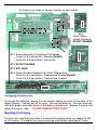
Jumpers
Although the ProScale display uses a keyboard-programming mode to set features in the
unit, several selection jumpers are located on the circuit board for special functions.
JP1
Absolute/Incremental Encoder Selection
The ProScale General Purpose Display supports both the Accurate Technology
incremental and absolute style systems. To configure the display for use with absolute
type encoders (default), install the shorting jumper in position A. For incremental type
encoders, (older Mitutoyo 950 Series using Incremental Technology) install the shorting
jumper in position B.
NOTE: This functionality is not related to the Absolute and Incremental measurement
modes described earlier.
JP2
JP4
FUTURE FEATURE DO NOT CHANGE !
Programming Mode Control
Entry to the programming mode of the ProScale display can be enabled or disabled
based on this jumper setting. To enable keyboard programming (default), install the
shorting jumper in position A. To disable keyboard programming, install the shorting
jumper in position B.
When programming mode is disabled, the user cannot access the programming functions
via the Mode/0 keys as described in the programming section. This provides the user
with a method of configuring the display with specific parameters and prevents
unauthorized configuration changes.
Mitutoyo America Corp. - ProScale Series 950 DRO
21 of 35
All Jumpers are shown in “storage” position for best visibility
JP 2
Future Option
Default Position=B
DO NOT CHANGE
JP 1
JP 1 Selects Absolute or Incremental Technology
Center Pin & A connected = Absolute (Default)
Center Pin & B connected = Incremental
JP 2 DO NOT CHANGE
JP 3 NOT USED
JP 4 Selects Enables/Disables Front Panel Programming
Center Pin & A connected = Programming Enabled (Default)
Center Pin & B connected = Programming Disabled
Changing the Batteries
To change the batteries, remove the two screws holding the cover to the base of the
display housing. Carefully pull off the cover. Remove the batteries. Reinstall new ones,
noting the proper orientation shown in the battery compartment. Replace the cover and
tighten the screws. Note:
DO NOT BEND BATTERY CLIPS!
Mounting the Display
There are four small mounting holes in the back of the display which may tapped for M2
or 4-40 screws. The display may also be mounted using double sided tape or Velcro.
Mitutoyo America Corp. - ProScale Series 950 DRO
22 of 35
SECTION 5
MISCELLANEOUS
Scales
Scales used for individual products should never be mixed. Try to avoid drilling through
the green portion of the scale. Any portion of the green that is drilled will not operate.
Note: Shortening 950-404/405 or 950-406/407 scales is not advised. Contact MAC for
assistance.
1.9mm (.07)
To shorten the incremental scales for an application,
follow these steps. The scale is embedded with stainlesssteel wires that could be damaged if not cut properly.
1. Use a grinder (such as a Moto Tool®) to grind through
the wires embedded in the sides of the scale.
2. Using a hacksaw, cut through the aluminum extrusion.
3. Use a file or sanding tool to chamfer the cut end to the
specifications shown in the illustration.
4. Remove all burrs.
5. Test the shortened scale by sliding a readhead on.
There should not be any binding.
6.3mm (.25")
Readheads
Readheads used for individual products should never be mixed. Avoid making extension
cables. If a different cable length is required, contact MAC. The pressure exerted on the
readhead by the guide clip should never cause the circuit board to press against the
green strip on the scale, as this will quickly wear out both components and void the
warranty. See the diagram in Section 3 more information about proper guide clip
spacing.
Mitutoyo America Corp. - ProScale Series 950 DRO
23 of 35
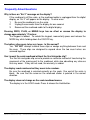
Frequently Asked Questions
Why is there an “Err 2” message on the display?
If the readhead is off the scale, or the readhead cable is unplugged from the digital
display, an “Err 2” will appear on the display. To clear error:
1.
Be sure the readhead is on the scale.
2.
Unplug the connector from the display for one second.
3.
Reconnect the readhead cable to the digital display.
Pressing ZERO, PLUS, or MINUS keys has no effect or causes the display to
change approximately 17 inches:
The keypad is locked. To unlock the keypad, momentarily press and release the
MODE key while holding down the ON/OFF key.
The battery clips seem to be very loose. Is this normal?
Yes. DO NOT attempt to bend these clips or wedge anything between them and
the case. These clips are designed to expand when the two case halves are
screwed together.
Can I mount the scale/readhead without the flex link/guide clip?
The flex link and guide clip serve to provide an accurate method of transferring the
movement of the moving part to the readhead, while also absorbing any stresses
that may occur. If they are not used, the warranty is voided.
The display reads numbers but they seem to be random.
Be sure the readhead is oriented correctly on the scale. One end of the scale is
black. Be sure that the arrow on the readhead sticker is pointed in the correct
direction.
The display does not change as the scale/readhead moves.
The display is in the HOLD mode. Press & release the Hold button.
Mitutoyo America Corp. - ProScale Series 950 DRO
24 of 35
Error Codes & Factory Service
ProScale warns if an error occurs by displaying "Err" plus a number on the display. If
error code 0, 1, 2, 3, 5, 6, 7, or 8 is displayed:
1. Check to be sure the readhead is on the scale.
2. Check all connections and cable for damage.
3. If the readhead is on the scale and all connections are good, unplug the readhead
from the display, wait 3 seconds, and reinstall it.
If error code 4 is displayed, the display is trying to display fractions over 99 63/64".
Switch to a decimal readout or press ZERO (and recalibrate) if this value is incorrect.
For further assistance, contact your supplier, or Mitutoyo America.
When calling for factory service, please have as much information about your product onhand. If possible, please have the following information:
1. Product name.
2. Any modification to the product.
3. The date of product purchase.
4. Detailed information about the problem, such as when, where, and how the problem
occurs, and the machinery being used nearby.
Communicating With Other Equipment
ProScale's electrical interface allows the read head position to be read by a computer or
other instrument. Refer to the electrical diagrams in Figures 5-2 through 5-7.
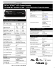
Read Head Output
Decimal Point
d1
d2
d3
d4
All "f" (1111)
d5
d6 d7
MSD
Sign
+: 0 (0000)
- : 8 (0001)
d8
d9 d10 d11 d12 d13
LSD
Measurement
Unit
mm: 0 (0000)
inch: 1 (1000)
X.X.X.X.XX
2 (0100)
3 (1100)
4 (0010)
5 (1010)
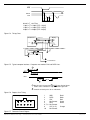
Figure 5-2. Data Format
CLK
DATA
122 T3
nom
244 T4
nom
122 T2
nom
Figure 5-3. Timing of CLK and DATA
Mitutoyo America Corp. - ProScale Series 950 DRO
25 of 35
REQ
DATA
CLK
T1 T2 T3
0.0mS ≤ T1 ≤
110µS ≤ T2 ≤
110µS ≤ T3 ≤
230µS ≤ T4 ≤
T4
93.75ms
140µS (TYP: 122µS)
140µS (TYP: 122µS)
260µS (TYP: 244µS)
Figure 5-4. Timing Chart
Read Head
Display
Power 1.5 v
CLK
3v
3v
DATA
1.5v
20 K
20 K
REQUEST
5v
5v CLK
5v
DATA
To Parallel I/O
Figure 5-5. Typical computer interface. Computer must monitor CLK and DATA lines.
1
up to 1 sec.
REQ
variable
1 to 85 ms
CLK
35 ms
50 ms
2
1
May be some recovery time after REQ goes high of about 1 second
before clocks and data are output when REQ goes low.
2
Contains 52 clock pulses for 13 4-bit words.
Figure 5-6. Request Line Timing
Display-Monitor Receptacle
9
10
7
8
5
3
1
6
4
2
1
2
3
4
5
6, 7, 8
9
10
GND
DATA
CLK
No Connect
REQ
No Connect
VCC (1.5v)
No Connect
Braid
Black
Red
Green
White
Orange
Figure 5-7. Connector Pinout Diagram
Mitutoyo America Corp. - ProScale Series 950 DRO
26 of 35
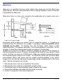
Abbe Error
Abbe error is a condition that may not be visible to the human eye, but will affect linear
measurements. Be sure to take precautions when installing ProScale in order to eliminate
the possibility for Abbe error.
Abbe error refers to a linear error caused by the combination of an angular error and a
dimensional offset between the sample and the measuring system. It is important to
understand that the information the encoder is providing is only the position of the
readhead on the scale. To illustrate this, see the figure, which shows a linear
measuring device. (The apparent distortion in the measuring device is intentional - for this
example - to show the measuring device with a curvature in its mounting.)
Suppose the curvature in the figure is sufficient to produce an angle of 40 arc-seconds. If
the measuring device moves 10 inches, the probe will be found to have moved 10.0039
inches, resulting in an error of +0.0039 inches. Abbe error could be lessened by moving
the measuring system closer to the sample. This effectively solves one half of the Abbe
error problem (offset) and leaves only the angular mounting problem to be solved.
Angular error can best be countered through proper design and placement of the linear
scale. Sources of angular error include:
1.
2.
3.
4.
5.
Mounting the linear scale to an imperfectly flat surface.
Mounting the linear scale to an imperfectly straight surface.
Curvature of ways (or linear bearings) used to measure the sample.
Contaminants between the probe and item being measured.
Friction in any part(s) of the measuring device.
Mitutoyo America Corp. - ProScale Series 950 DRO
27 of 35
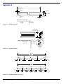
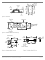
Appendix A
L
.30" (7.6)
.25" (6.35)
.75" (19.05)
Tapped for
10-32
.25" (6.35)
L
MEASURING RANGE (MR)
Figure A-1. 950-404 & 950-405
10" (250)
18" (450)
14.25" (362)
22.25" (565)
Countersink Min.
depth of #6 screw
.125" (3.18)
MEASURING RANGE (MR)
52" (1.32)
96" (2.44)
L
L
56" (1.42)
100" (2.54)
Enlarged
View
Figure A-2. 950-406 & 950-407
56"
4"
12"
12"
12"
12"
4"
100"
2"
16"
16"
16"
16"
16"
16"
2"
Figure A-3. 950-406 & 950-407 Hole Pattern
Mitutoyo America Corp. - ProScale Series 950 DRO
28 of 35
1.81"
(45.97)
.195" Dia.
(4.95)
.62"
(15.75)
.795"
(20.19)
2.81"
(71.37)
3.12"
(79.25)
.09"
(2.28)
.156" Dia.
(3.96)
3 places
1.5"
(38.1)
Figure A-4. Read Head
Guide Clip
Housing
.955"
(24.26)
.835"
(21.21)
Recommended
for proper TAB
flex
1.3"
(33.0)
Scale
Extrusion
Figure A-5. 950-406 & 950-407 Scale and Housing
For #8 fastener
.158"
(40.13)
1.10"
(27.94)
1.85"
(47.0)
.75"
(19.05)
.185"
(4.7)
.38" (9.65)
.75"
(19.05)
.25"
(6.35)
2.5"
(63.5)
1.3"
(33.02)
Figure A-6. 950-406 & 950-407 Guide Clip
Mitutoyo America Corp. - ProScale Series 950 DRO
.187" Dia.
(4.75)
for #10 Fastener
1.85"
(47.0)
Figure A-7. 950-404 & 950-405 Flex Link
29 of 35
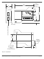
Cover
Attaching
Screws
4.45"
(113.0)
1.5"
(38.1)
.5"
(12.7)
3.1"
(78.7)
ON/OFF
MODE
+
0
-
.34"
(8.6)
SPC Output
Readhead Input Connector
16" (2.95)
1.55"
(39.4)
Modular
Connector
This Side
.18" (4.57) Dia.
Knockout Holes
4 Places
for Display Mounting
3.44"
(87.4)
.52"
(13.2)
Figure A-8. Digital Monitor
Mitutoyo America Corp. - ProScale Series 950 DRO
30 of 35
SECTION 6
ACCESSORIES
ProMUX-3
The ProMux 3™ is an easy to use hardware interface device providing communication
and control of one to three ProScale ABS linear encoders from a user provided PC or
PLC.
Supplied are two separate components. First is the ProMux 3 interface unit and second
is a low voltage plug-in power supply. The user must provide the host PC or PLC and a
standard DB-9 serial cable (male to female).
Uses for the ProMux 3 include axis position measurement on XY or XYZ quality control
measurement tables, machinery position control (NON-CNC), tooling measurement
devices and the like.
Specifications:
Encoder Inputs:
3 ProScale ABS readheads.
Serial Interface:
RS-232 DB-9 connector.
8 bit word, no parity, 1 stop bit
No flow control.
Mitutoyo America Corp. - ProScale Series 950 DRO
31 of 35
ProMUX-4, ProMUX-8
The ProMUX™ series of linear encoder multiplexers are designed for OEM and system
integrators for use in acquiring setup positional information (non-CNC) on industrial
production machinery.
The multiplexers interface directly with ProScale absolute linear measurement encoders.
ProMUX 4/8 multiplexers communicate with a host PC or PLC via RS-232 or RS-422
serial interface. Various baud rates are supported from 9600 to 115200. Up to 15
multiplexers can be connected to the same communications bus when utilizing the RS422 serial interface.
•
•
•
•
•
•
•
14 – 24 VDC power supply operation.
RS-232 or RS-422 serial interface with multiple baud rates.
Supports 4 or 8 ProScale™ linear measurement encoders.
Provides position update of all eight channels every 100 milliseconds.
Robust aluminum mounting enclosure: 130mm W x 105mm D x 45mm H.
Positional data preformatted into ASCII strings.
Programmable data packet checksum operation.
Mitutoyo America Corp. - ProScale Series 950 DRO
32 of 35
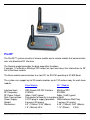
Pro RF
The Pro-RF™ system consists of a base module and a remote module that communicate
over a bi-directional RF interface.
The Remote module provides the data acquisition functions.
It accepts 1 ProScale or Mitutoyo SPC output as input and relays the information via RF
link to the Base module.
The Base module communicates to a host PC via RS-232 operating at 57,600 Baud.
The system can support up to 32 remote modules up to 100 meters away for each base
module.
Base Module
RF-1 Module
Interface/Input :
RF Frequency:
RF Power Output:
Data Transmission:
Power Supply:
Weight:
Dimensions:
DB9 Female RS-232 Interface
Mitutoyo SPC
916 MHz
916 MHz
0dbm (1mW) typical
0dbm (1mW) typical
Data packet w/security & checksum (Both)
9 VDC plug-in supply (provided) NiMh batteries/Wall Plug
5 ounces (22 grams)
7 ounces (31 grams)
5.3” (135mm), 3.35” (85mm)
4.25” (108mm), 2.60” (66mm),
1.5” (38mm)L,W,H
1.14” (29mm)
L,W,H
Mitutoyo America Corp. - ProScale Series 950 DRO
33 of 35
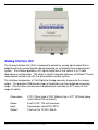
Analog Interface Unit
The Analog Interface Unit (AIU) is designed to provide an analog signal output that is
proportional to the current position being displayed on a ProScale linear measurement
system. The interface provides a DC signal range from 0 to 5 volts or 0 to 10 volts
depending on configuration. This offers a simple integration between a ProScale™ linear
measurement system and a PLC or other process control system.
The interface incorporates a 12-bit Digital-to-Analog converter to generate the analog
output. This provides 4096 discrete steps of resolution over the configured measuring
range. This can offer a measurement displacement resolution of .001” over a 4-inch
range of motion
Dimensions:
2.75” (70mm) wide x 3.38” (86mm) high x 2.27” (57.6mm) deep.
(Uses 35mm DIN rail mount.)
Power:
8 to 24 VDC, 100 mA maximum.
Input:
Synchronous serial BCD (SPC)
Output:
0 to 5 or 0 to 10 VDC, 60mA
Mitutoyo America Corp. - ProScale Series 950 DRO
34 of 35
Mitutoyo America Corp. - ProScale Series 950 DRO
35 of 35