1
Table of Contents
HVAC PRO User’s Guide
Table of Contents
Chapter 1
HVAC PRO User’s Guide.............................................. 1
Getting Started with HVAC PRO Software ........................1-1
Introduction...................................................................................................... 1-1
Key Concepts................................................................................................... 1-2
HVAC PRO Software .....................................................................................................1-2
Main Window..................................................................................................................1-3
Display Buttons ..............................................................................................................1-3
List Boxes.......................................................................................................................1-4
Online Help ....................................................................................................................1-4
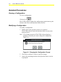
Detailed Procedures........................................................................................ 1-5
Starting HVAC PRO Software ........................................................................................1-5
Exiting HVAC PRO Software .........................................................................................1-5
Chapter 1
Getting Started with HVAC PRO Software ........................1-1
Introduction...................................................................................................... 1-1
Key Concepts................................................................................................... 1-2
HVAC PRO Software .....................................................................................................1-2
Main Window..................................................................................................................1-3
Display Buttons ..............................................................................................................1-3
List Boxes.......................................................................................................................1-4
Online Help ....................................................................................................................1-4
Detailed Procedures........................................................................................ 1-5
© April, 2001 Johnson Controls, Inc.
www.johnsoncontrols.com
2
Tools
Starting HVAC PRO Software ........................................................................................1-5
Exiting HVAC PRO Software .........................................................................................1-5
Chapter 2
Creating, Saving, and Printing Configurations ................2-1
Introduction...................................................................................................... 2-1
Key Concepts................................................................................................... 2-2
Question/Answer Session ..............................................................................................2-2
Automatic File Upgrade..................................................................................................2-2
Configuration File Types ................................................................................................2-4
Saving a Configuration...................................................................................................2-5
Save As Option ..............................................................................................................2-5
Target Device.................................................................................................................2-5
Print Format ...................................................................................................................2-5
Procedure Overview........................................................................................ 2-6
Detailed Procedures........................................................................................ 2-7
Creating a New Configuration ........................................................................................2-7
Opening a Configuration ................................................................................................2-8
Closing a Configuration..................................................................................................2-8
Saving a Configuration...................................................................................................2-9
Using the Save As Option ..............................................................................................2-9
Printing a Configuration................................................................................................2-12
Changing the Print Format ...........................................................................................2-12
Troubleshooting ............................................................................................ 2-13
Saving a Configuration.................................................................................................2-13
Chapter 3
Downloading Configurations and VMA Code...................3-1
Introduction...................................................................................................... 3-1
Key Concepts................................................................................................... 3-2
Configuration Download.................................................................................................3-2
VMA Code Download.....................................................................................................3-2
Procedure Overview........................................................................................ 3-3
Detailed Procedures........................................................................................ 3-4
Table of Contents
3
Downloading the Current Configuration .........................................................................3-4
Downloading VMA Code ................................................................................................3-8
Troubleshooting ............................................................................................ 3-11
Chapter 4
Uploading and Upgrading Configurations........................4-1
Introduction...................................................................................................... 4-1
Key Concepts................................................................................................... 4-2
Automatic File Upgrade..................................................................................................4-2
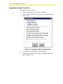
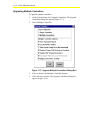
Upgrade Controllers Command .....................................................................................4-2
Upgrade Controller Options ...........................................................................................4-4
Procedure Overview........................................................................................ 4-6
Detailed Procedures........................................................................................ 4-7
Uploading a Configuration..............................................................................................4-7
Upgrading a Single Controller ........................................................................................4-8
Upgrading Multiple Controllers.....................................................................................4-10
Troubleshooting ............................................................................................ 4-14
Uploading a Configuration............................................................................................4-14
Chapter 5
Commissioning a Controller ..............................................5-1
Introduction...................................................................................................... 5-1
Key Concepts................................................................................................... 5-2
Commission Mode .........................................................................................................5-2
Commission Using the Configuration in the Controller...................................................5-2
Exiting Commission Mode in TC-9100 Controllers and VMA1400 Series Devices........5-3
Sensor Calibration in Using the AI Offset Table for ASC Devices .................................5-3
Override Release in Commission Mode.........................................................................5-3
Controller Resetting .......................................................................................................5-4
Procedure Overview........................................................................................ 5-5
Detailed Procedures........................................................................................ 5-6
Commissioning a Controller Using the Current Configuration........................................5-6
Commissioning Using the Configuration in the Controller..............................................5-7
Calibrating Sensors Using the AI Offset Table for ASC Devices ...................................5-8
4
Tools
Releasing All Overrides..................................................................................................5-9
Exiting Commission Mode for ASC Devices ..................................................................5-9
Exiting Commission Mode for TC-9100 Controllers .....................................................5-12
Exiting Commission Mode for VMA1400 Series Devices.............................................5-13
Resetting a Controller ..................................................................................................5-15
Chapter 6
Viewing and Modifying Configurations.............................6-1
Introduction...................................................................................................... 6-1
Key Concepts................................................................................................... 6-2
Question/Answer (Q/A) List Box ....................................................................................6-2
Procedure Overview........................................................................................ 6-3
Detailed Procedures........................................................................................ 6-4
Viewing a Configuration .................................................................................................6-4
Modifying a Configuration ..............................................................................................6-4
Chapter 7
Viewing and Modifying Configuration Inputs ...................7-1
Introduction...................................................................................................... 7-1
Key Concepts................................................................................................... 7-2
Inputs List Box................................................................................................................7-2
Pressure Sensor Analog Input Ranges for ASC Devices...............................................7-2
User-defined Ranges for VMA Inputs ............................................................................7-3
Procedure Overview........................................................................................ 7-5
Detailed Procedures........................................................................................ 7-6
Viewing and Modifying Analog Inputs and Binary Inputs ...............................................7-6
Modifying ASC Analog Inputs ........................................................................................7-6
Modifying ASC Binary Inputs .......................................................................................7-10
Modifying ASC Analog Inputs in Commission Mode ....................................................7-11
Modifying ASC Binary Inputs in Commission Mode .....................................................7-13
Modifying TC-9100 Controller Analog Inputs ...............................................................7-14
Modifying TC-9100 Controller Binary Inputs ................................................................7-15
Modifying TC-9100 Controller Analog Inputs and Binary Inputs in Commission Mode 7-16
Modifying VMA Analog and Binary Inputs ....................................................................7-17
Table of Contents
5
Defining a Range for VMA Inputs.................................................................................7-19
Modifying VMA Analog and Binary Inputs in Commission Mode .................................7-21
Troubleshooting ............................................................................................ 7-24
Chapter 8
Viewing and Modifying Configuration Outputs ................8-1
Introduction...................................................................................................... 8-1
Key Concepts................................................................................................... 8-2
Outputs List Box.............................................................................................................8-2
ASC Binary Output Min-On/Min-Off Value Conversion ..................................................8-2
ASC Staged Binary Output Cycles/Hour Value Conversion...........................................8-3
Procedure Overview........................................................................................ 8-4
Detailed Procedures........................................................................................ 8-5
Viewing and Modifying Analog Outputs (AOs) and Binary Outputs (BOs) ....................8-5
Modifying ASC Analog Outputs......................................................................................8-5
Modifying ASC Binary Outputs.......................................................................................8-7
Modifying ASC Staged Binary Outputs ..........................................................................8-9
Modifying ASC Analog Outputs in Commission Mode .................................................8-10
Modifying ASC Binary Outputs in Commission Mode ..................................................8-12
Modifying TC-9100 Controller Analog Outputs ............................................................8-14
Modifying TC-9100 Controller Binary Outputs .............................................................8-15
Modifying TC-9100 Controller Analog Outputs in Commission Mode ..........................8-16
Modifying TC-9100 Controller Binary Outputs in Commission Mode ...........................8-18
Modifying VMA Analog and Binary Outputs .................................................................8-19
Modifying VMA Additional Outputs...............................................................................8-21
Modifying VMA Outputs in Commission Mode .............................................................8-25
Troubleshooting ............................................................................................ 8-30
Chapter 9
Viewing and Modifying Configuration Parameters ..........9-1
Introduction...................................................................................................... 9-1
Key Concepts................................................................................................... 9-2
Parameters List Box.......................................................................................................9-2
Commission Mode Overrides .........................................................................................9-2
6
Tools
Procedure Overview........................................................................................ 9-3
Detailed Procedures........................................................................................ 9-4
Expanding and Collapsing Parameter Groups ...............................................................9-4
Modifying Analog Parameters for ASC and TC Controllers ...........................................9-4
Modifying Binary Parameters for ASC and TC Controllers ............................................9-5
Modifying Time Parameters for ASC and TC Controllers...............................................9-6
Modifying Analog Parameters for VMA Devices ............................................................9-7
Modifying Binary Parameters for VMA Devices .............................................................9-8
Modifying Multistate Parameters for VMA Devices ........................................................9-9
Modifying Parameters in Commission Mode for ASC and TC Controllers ...................9-10
Modifying Parameters in Commission Mode for VMA Devices ....................................9-13
Chapter 10
Setting HVAC PRO Options ..........................................10-1
Introduction.................................................................................................... 10-1
Key Concepts................................................................................................. 10-2
FILES Path...................................................................................................................10-2
Job Information ............................................................................................................10-2
Generate DDL on Save................................................................................................10-2
Generate PRN on Save ...............................................................................................10-2
Parameter Prompting ...................................................................................................10-2
Window Style ...............................................................................................................10-3
Viewing Available VMA Screens ..................................................................................10-5
Procedure Overview...................................................................................... 10-6
Detailed Procedures...................................................................................... 10-7
Setting the FILES Path.................................................................................................10-7
Setting Job Information ................................................................................................10-8
Generating a DDL on Save ..........................................................................................10-9
Generating a PRN on Save..........................................................................................10-9
Activating Parameter Prompting ..................................................................................10-9
Changing Window Style .............................................................................................10-10
Changing VMA Screens .............................................................................................10-10
Chapter 11
Using Sideloops .............................................................11-1
Table of Contents
7
Introduction.................................................................................................... 11-1
Key Concepts................................................................................................. 11-2
Sideloop List Box .........................................................................................................11-2
Sideloop View and Modify Dialog Box .........................................................................11-3
Procedure Overview...................................................................................... 11-4
Detailed Procedures...................................................................................... 11-5
Defining a New Sideloop..............................................................................................11-5
Selecting a Predefined Hardware Point .......................................................................11-6
Defining an Unused Point or Modifying a Predefined Point .........................................11-7
Defining or Modifying Multiple AIs ................................................................................11-7
Changing the Sideloop Name ......................................................................................11-8
Changing Sideloop Inputs, Outputs, or Parameters.....................................................11-8
Changing Answers in the Sideloop Question/Answer Path..........................................11-8
Chapter 12
Using a Template File for Commissioning ..................12-1
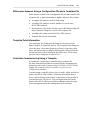
Introduction.................................................................................................... 12-1
Key Concepts................................................................................................. 12-2
Template Files..............................................................................................................12-2
Similarities between Configuration and Template Files ...............................................12-2
Differences between Using a Configuration File and a Template File .........................12-3
Template Point Information ..........................................................................................12-3
Controller Commissioning Using a Template ...............................................................12-3
Decimal Precision and Updating Point Values .............................................................12-5
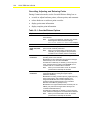
Monitoring and Graphing Controller Data Using a Template File.................................12-5
Creating and Customizing a Template File ..................................................................12-7
Procedure Overview...................................................................................... 12-9
Detailed Procedures.................................................................................... 12-10
Opening a Template File............................................................................................12-10
Displaying the Template Point Dialog Box .................................................................12-11
Commissioning a Controller Using a Template File ...................................................12-11
Using Data Graphing..................................................................................................12-13
Template File Syntax, Layout, and Examples ........................................... 12-15
8
Tools
Template File Syntax .................................................................................................12-15
Syntax Rules ..............................................................................................................12-15
Description of Keywords ............................................................................................12-16
Template File Layout..................................................................................................12-26
Template Files for DDL Users ....................................................................................12-27
Template File Examples.............................................................................................12-28
Chapter 13
Using Loop Tuning for ASC Devices ...........................13-1
Introduction.................................................................................................... 13-1
Key Concepts................................................................................................. 13-2
Loop Tuning .................................................................................................................13-2
Considerations Before Loop Tuning.............................................................................13-2
Monitoring a Loop or Data Points.................................................................................13-4
Tuning a Loop Using PRAC .........................................................................................13-4
PRAC Misapplications..................................................................................................13-5
Time Required for PRAC Tuning .................................................................................13-5
Graphing Data File Format...........................................................................................13-5
Procedure Overview...................................................................................... 13-7
Detailed Procedures...................................................................................... 13-8
Accessing the Loop Tuning Feature ............................................................................13-8
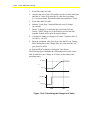
Overriding the PI Setpoint ..........................................................................................13-15
Modifying the Vertical Axis .........................................................................................13-15
Modifying the Time Axis .............................................................................................13-17
Starting Pattern Recognition Adaptive Control (PRAC) .............................................13-18
Verifying Process Performance..................................................................................13-19
Tuning a Sample Loop with PRAC.............................................................................13-20
Adjusting Loop Tune Parameters...............................................................................13-21
Troubleshooting .......................................................................................... 13-23
Chapter 14
Using Data Graphing .....................................................14-1
Introduction.................................................................................................... 14-1
Key Concepts................................................................................................. 14-2
Data Graphing..............................................................................................................14-2
Table of Contents
9
Procedure Overview...................................................................................... 14-3
Detailed Procedures...................................................................................... 14-4
Creating a Graph..........................................................................................................14-4
Modifying the Vertical Axis ...........................................................................................14-6
Modifying the Time Axis ...............................................................................................14-7
Troubleshooting ............................................................................................ 14-8
Chapter 15
Testing and Receiving Data from Controllers .............15-1
Introduction.................................................................................................... 15-1
Key Concepts................................................................................................. 15-2
Action Menu .................................................................................................................15-2
Controller Information...................................................................................................15-2
VAV Box Flow Test ......................................................................................................15-3
VAV Diagnostics ..........................................................................................................15-3
VMA Balancer Tool ......................................................................................................15-3
VAV Flow Deadband....................................................................................................15-3
Recalculate Flow Tuning Parameters ..........................................................................15-4
Import AHU DOS Config ..............................................................................................15-5
Reset Controllers .........................................................................................................15-5
ASC Zone Bus Communication ...................................................................................15-5
VMA Controller Software Addressing...........................................................................15-6
Procedure Overview...................................................................................... 15-7
Detailed Procedures...................................................................................... 15-9
Receiving Controller Information on a Single Device ...................................................15-9
Receiving Controller Information on All Devices on the N2 Bus ................................15-11
Setting VMA Controller N2 Software Addresses ........................................................15-14
Testing a Single VAV Box ..........................................................................................15-14
Testing Multiple VAV Boxes .......................................................................................15-17
Collecting VAV Diagnostics........................................................................................15-20
Using the VMA Balancer Tool ....................................................................................15-21
Setting the VAV Flow Deadband................................................................................15-24
Recalculating Flow Tuning Parameters .....................................................................15-24
10
Tools
Importing AHU DOS Configurations...........................................................................15-25
Resetting Controllers..................................................................................................15-26
Chapter 16
Using HVAC PRO Software from the OWS ..................16-1
Introduction.................................................................................................... 16-1
Key Concepts................................................................................................. 16-2
Installation ....................................................................................................................16-2
Options for Accessing HVAC PRO Software from the OWS........................................16-2
Differences when Using HVAC PRO Software from the OWS.....................................16-3
VMA Download ............................................................................................................16-4
Download VMA Code...................................................................................................16-4
Commissioning.............................................................................................................16-5
Procedure Overview...................................................................................... 16-6
Detailed Procedures...................................................................................... 16-8
Downloading the Current Configuration .......................................................................16-8
Uploading the Configuration in the Controller ..............................................................16-9
Upgrading a Single Controller ....................................................................................16-10
Upgrading Multiple Controllers...................................................................................16-12
Commissioning the Current Configuration .................................................................16-14
Commissioning the Configuration in the Controller ....................................................16-15
Viewing Controller Information for a Single Device ....................................................16-16
Viewing Controller Information for All Devices on the Selected Network Controller (NC)16-17
Testing a Single VAV Box ..........................................................................................16-19
Testing Multiple VAV Boxes .......................................................................................16-21
Collecting VAV Diagnostics........................................................................................16-23
Troubleshooting .......................................................................................... 16-25
Chapter 17
Using HVAC PRO Software in Pass Through Mode ...17-1
Introduction.................................................................................................... 17-1
Key Concepts................................................................................................. 17-2
HVAC PRO Software in Pass Through Mode ..............................................................17-2
Site Book......................................................................................................................17-2
Pass Through vs. Standard Mode................................................................................17-2
Table of Contents
11
Differences when Using Pass Through Mode ..............................................................17-2
VMA Download ............................................................................................................17-4
Download VMA Code...................................................................................................17-4
Procedure Overview...................................................................................... 17-5
Detailed Procedures...................................................................................... 17-7
Starting HVAC PRO Software in Pass Through Mode.................................................17-7
Starting HVAC PRO Software in Standard Mode.........................................................17-7
Downloading the Current Configuration .......................................................................17-8
Uploading the Configuration in the Controller ..............................................................17-9
Upgrading a Single Controller ....................................................................................17-10
Upgrading Multiple Controllers...................................................................................17-12
Commissioning the Current Configuration .................................................................17-15
Commissioning the Configuration in the Controller ....................................................17-16
Viewing Controller Information for a Single Device ....................................................17-17
Viewing Controller Information for All Devices on the Selected Supervisory Controller17-18
Testing a Single VAV Box ..........................................................................................17-20
Testing Multiple VAV Boxes .......................................................................................17-22
Collecting VAV Diagnostics........................................................................................17-25
Chapter 18
Networking Controllers .................................................18-1
Introduction.................................................................................................... 18-1
Key Concepts................................................................................................. 18-2
HVAC PRO User’s Guide
1-1
Chapter 1
Getting Started with HVAC PRO
Software
Introduction
HVAC PRO™ software is an application used to configure control
strategies and to upload, upgrade, download, and commission
controllers. Use this application with controllers connected to
Metasys® Companion™/Facilitator™ controllers integrated with the
Metasys Network through a Network Control Module (NCM), or
controllers connected to the N30 Supervisory Controller.
This chapter describes how to:
•
start HVAC PRO software
•
exit HVAC PRO software
© November 1, 2001 Johnson Controls, Inc.
Code No. LIT-63750402
www.johnsoncontrols.com
Software Release 8.03
1-2
HVAC PRO User’s Guide
Key Concepts
HVAC PRO Software
Use HVAC PRO software to configure control strategies, which
contain software points and processes. A software point represents and
characterizes a field device (such as an Analog Input) or a data point
(such as a Binary Data point). A process is a set of logical evaluations
that determine when to perform an action, such as when to turn on a
supply fan or enable a chiller. HVAC PRO software translates each
process into a process object, which is downloaded to and executed by
the controller.
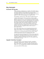
In addition to configuration utilities, HVAC PRO software provides
features to upload, upgrade, download, and commission controllers.
For Variable Air Volume Modular Assembly (VMA) 1400 Series
devices, use the download feature to upgrade the controller firmware
code. These utilities are described in detail later in this document.
HVAC PRO software is easy to use and quickly learned. Once you
know the basics, you’ll quickly move from window to window,
efficiently programming your controller.
HVAC PRO User’s Guide
1-3
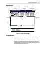
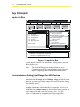
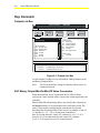
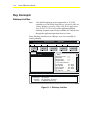
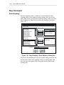
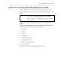
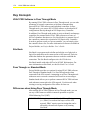
Main Window
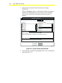
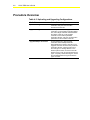
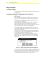
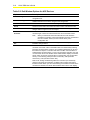
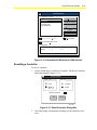
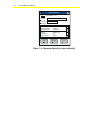
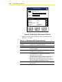
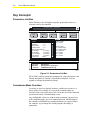
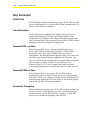
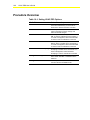
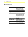
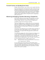
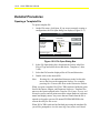
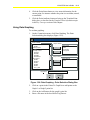
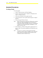
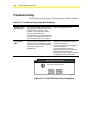
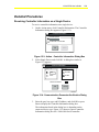
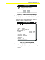
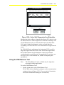
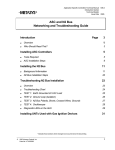
Figure 1-1 shows the basic HVAC PRO main window.
Title Bar
Minimize Button
Menu Bar
Close Button
Johnson Controls - HVAC PRO
File
Download
Upload
Commission
Action
Options
Help
Display Buttons
Q/A
INPUTS
OUTPUTS
Current Question/Answer Path
PARAMS
SIDELOOP
Parameters
Right List Box
Left List Box
Scroll Bar
Date: 01/03/00
Device Type:
Application:
Filename:
Time: 7:32:32 AM
Unnamed
Unnamed
C:\WINPRO\*.cfg
HPROWIN
Figure 1-1: HVAC PRO Window
Display Buttons
The display buttons Q/A (Question and Answer), Inputs, Outputs,
Params (Parameters), and Sideloop control the information displayed
in the list boxes. When you select a display button, the information
specific to that button fills the next available list box. The next
available box alternates between the left and right sides of the screen.
If the information for a display button is already displayed, its list box
moves to the opposite side of the screen.
1-4
HVAC PRO User’s Guide
List Boxes
There are two list boxes in HVAC PRO software. These boxes display
a list of the questions and answers, hardware inputs, outputs,
parameters, or sideloops. Select the information to display by using the
Display buttons. Move between the list boxes by using the Tab key or
by clicking the mouse in the list box.
Note:
You must have an open configuration in
HVAC PRO software to display information in the list
boxes.
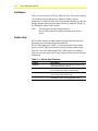
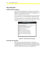
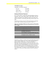
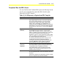
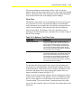
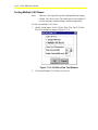
Online Help
HVAC PRO software includes Online Help that describes the basic
procedures for performing functions within the
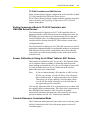
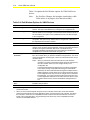
HVAC PRO application. Table 1-1 lists descriptions of help menu
features. HVAC PRO software also contains context sensitive help.
Press F1 at any time while using HVAC PRO software to display a
Help screen on the topic most closely related to what you are currently
working on.
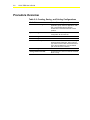
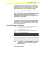
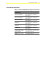
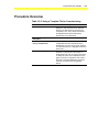
Table 1-1: Online Help Features
Feature
Description
Contents
Selecting Contents from the Help menu brings up the
help system’s table of contents.
Search for Help on. . .
Selecting Search for Help on... allows you to search
for more information about a particular topic.
How to Use Help
Selecting How to Use Help provides more information
on the way the help system works.
About HVAC PRO. . .
Selecting About HVAC PRO... displays the dialog box
with release version and copyright information.
HVAC PRO User’s Guide
1-5
Detailed Procedures
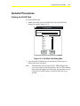
Starting HVAC PRO Software
To start HVAC PRO software:
1.
On the Windows Start menu, click Programs > Configuration
Tools > HVAC PRO. The HVAC PRO Copyright screen appears
for approximately 10 seconds.
2.
Press the Enter or Escape (Esc) key, or click with the mouse
anywhere on the Copyright screen to move past the display and
into HVAC PRO software.
Note:
To permanently disable the Copyright screen from
displaying, click on the square box next to the Do not show
this Copyright statement.
Exiting HVAC PRO Software
To exit HVAC PRO software, on the File menu, click Exit.
Note:
If you select Exit while a configuration is in process,
HVAC PRO software prompts you to save changes.
HVAC PRO User’s Guide
2-1
Chapter 2
Creating, Saving, and Printing
Configurations
Introduction
HVAC PRO software provides a Question/Answer session to set up
specific configurations for the mechanical system.
This chapter describes how to:
•
create a new configuration
•
open a configuration
•
close a configuration
•
save a configuration
•
use the Save As option
•
print a configuration
•
change the print format
© November 1, 2001 Johnson Controls, Inc.
Code No. LIT-63750403
www.johnsoncontrols.com
Software Release 8.03
2-2
HVAC PRO User’s Guide
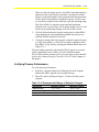
Key Concepts
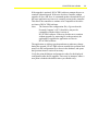
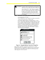
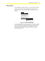
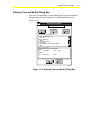
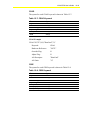
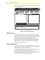
Question/Answer Session
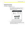
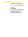
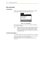
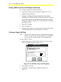
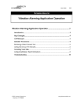
HVAC PRO software displays a series of questions for the selected
application. Use the Question/Answer session to set up specific control
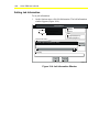
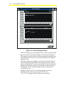
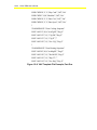
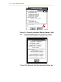
sequences for the mechanical system. Figure 2-1 is an example of a
question in the Question/Answer session.
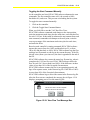
The system identifies the input and output hardware points and updates
the parameter list box as you work through the configuration process.
If you change an answer to a previous question, all questions after the
changed selection must be re-answered. The previous answers become
the default selections for this Question/Answer session.
Question/Answer Session
Select the VAV control strategy:
Pressure Independent
Constant Volume with separate dampers
Constant Volume with linked dampers
Single duct conversion
Ind. cold deck with dep. hot deck
Pressure Independent (Disch Air Reset)
CV with sep. dampers (Disch Air Reset)
Pressure Independent (User defined flow)
CV with sep. dampers (User defined flow)
VAVQA
Figure 2-1: Question/Answer Session
Automatic File Upgrade
When opening an existing configuration, HVAC PRO software
compares the application and sideloop path revision numbers stored in
the configuration file with the revision numbers in the database. If the
configuration file used an earlier version of the application or sideloop
paths, HVAC PRO software prompts you to upgrade the file.
HVAC PRO User’s Guide
2-3
If the upgrade is optional, HVAC PRO software prompts the user to
continue without upgrade. If the user decides to continue without
upgrade, all Save and Save As commands produce download files of
the same application revision as is currently present in the controller.
This allows the controller to continue to be compatible with earlier
revisions of HVAC PRO software.
Note:
The format of the configuration file (.cfg) saved on the
Personal Computer’s (PC’s) hard drive may not be
compatible with the earlier versions of
HVAC PRO software. If the user decides not to continue
without upgrade (by answering No to the question), the
application is upgraded to application revision in
HVAC PRO software.
The application or sideloop question and answer paths may change
during the upgrade. HVAC PRO software matches the questions and
answers in the configuration file to those in the database, and opens
the Question/Answer session if necessary.
Verify the point definitions and parameter values for the displayed
configuration after the file upgrade. There may be instances where a
new point is loaded with default values you should verify.
2-4
HVAC PRO User’s Guide
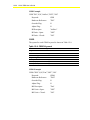
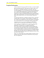
Configuration File Types
HVAC PRO software automatically generates several file types when
you save a configuration. Table 2-1 lists the HVAC PRO software
generated file types and their functions.
Table 2-1: HVAC PRO Software Generated Files
Controller
Extension
Function
All
Controllers
.cfg
The configuration file. HVAC PRO software
creates this file when you save the configuration.
.dat
The graphing file. HVAC PRO software creates
this file while you are monitoring control loops or
data points. You can rename this file.
.ddl
The optional DDL incremental source file for the
Control System (CS) Model. HVAC PRO software
creates this file after saving a configuration if you
select Generate DDL on Save in the Options
menu. Refer to the Setting HVAC PRO Options
(LIT-63750411) chapter in this guide.
.err
The error file. HVAC PRO software creates this file
if there are errors when you save the configuration
or if errors occur when you open a template file.
.prn
The optional print file. HVAC PRO software
creates this file after saving a configuration if you
select Generate PRN on Save in the Options
menu.
ASC
.asc
The downloadable object file for an ASC. Not
created if you select No Target Device when
saving a configuration (see Save As Option in this
section).
TC
.tcd
The TC-9100 download file created during the
File > Save/Save As process for a TC-9100
configuration at Metasys Release 9.01 or later.
The TC-9100 download file is not created if you
select No Target Device when saving a
configuration.
VMA
.mab
The Metasys Application BASIC file created by
HVAC PRO software. This file defines the
VMA1400 Series application that results from the
Question/Answer session.
.mao
The Metasys Application Object file created during
the File > Save/Save As process. This file is
downloaded into the VMA1400 Series device.
.mau
The Metasys Application User Information file used
during download process. This file contains user
information that enables a later upload.
HVAC PRO User’s Guide
2-5
Saving a Configuration
If you add, delete, or change any information in a window, save
changes using the current name and target device.
However, in rare cases, the amount of information stored in an
Application Specific Controller (ASC) device to recreate the original
configuration may exceed the available space. If this occurs during the
Save process, a message warns you that it will not be able to upload
the configuration.
Save As Option
Use the Save As option to save new configurations or any changes in
an existing configuration and assign a new device type, name, and/or
directory for storage. This menu item appears dimmed when the
configuration is incomplete.
Target Device
The target device is the type of controller for the configuration
download. Controllers capable of running the configured application
appear in the Devices list box. Controllers not capable of running the
configured application appear in the Devices Not Allowed list box.
Print Format
Print a formatted version of the controller’s Configuration file when
you finish configuring an application. The Print selection is
unavailable when a configuration is not complete.
When printing a configuration, select either short or long format for
the printed configuration file.
The short format consists of project information, the Question/Answer
session, general information on inputs and outputs, and parameter
information.
The long format consists of project information, the Question/Answer
session, detailed information on inputs and outputs, and parameter
information.
2-6
HVAC PRO User’s Guide
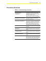
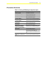
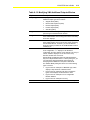
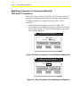
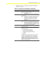
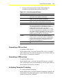
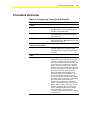
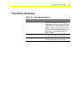
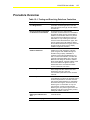
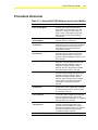
Procedure Overview
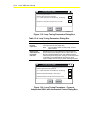
Table 2-2: Creating, Saving, and Printing Configurations
To Do This
Follow These Steps:
Create a New Configuration
On the File menu, click New. Select an
application group. Select an application. Click
OK. In the Question/Answer Session,
double-click on the desired answer to each
question.
Open a Configuration
On the File menu, click Open. Select the
configuration file and click OK.
Close a Configuration
On the File menu, click Close.
Save a Configuration
On the File menu, click Save.
Use the Save As Option
On the File menu, click Save As. In the Target
Device Selection dialog box, select a device
type. Select a device from the Devices list box.
In the Save As dialog box, type the desired
path and/or file name. Click OK.
Print a Configuration
On the File menu, click Print.
Change the Print Format
On the File menu, click Print Format and either
Short or Long.
HVAC PRO User’s Guide
2-7
Detailed Procedures
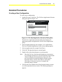
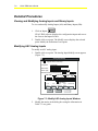
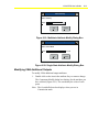
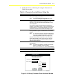
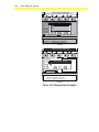
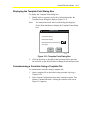
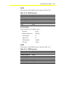
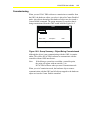
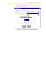
Creating a New Configuration
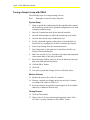
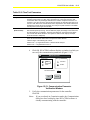
To create a new configuration:
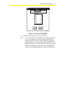
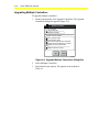
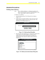
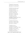
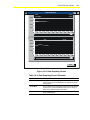
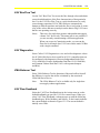
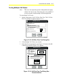
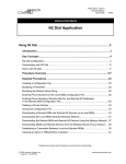
1.
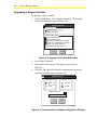
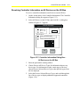
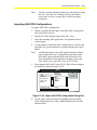
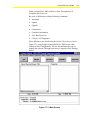
On the File menu, click New. The File New/Application Selection
dialog box appears (Figure 2-2).
File New / Application Selection
Application Group:
VAV Applications
Applications:
Single Duct
Dual Duct
VMA Single Duct
VMA Dual Duct
OK
Cancel
NEWAP
Figure 2-2: File New/Application Selection Dialog Box
The File New/Application Selection dialog box displays all
application groups and applications for the selected application
group.
2.
Select an application group (for example, VAV Applications).
The list of available applications for the selected group appears.
3.
Select an application (for example, Dual Duct).
4.
Click OK. The Question/Answer session begins.
5.
Double-click on the desired answer to each question.
Note:
6.
Press the Esc key to back up and change previous answers.
If you change an answer to a previous question, all questions
after the changed selection must be re-answered. The
previous answers become the default selections for this
Question/Answer session. Press Enter to select these
selections or select new answers to complete the
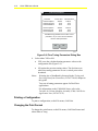
Question/Answer Session.
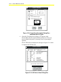
Click on the Close Window box of the Question/Answer session
to exit the Question/Answer session. The following dialog box
appears.
2-8
HVAC PRO User’s Guide
Question/Answer Session
This Q/A Session is not complete. Exiting now will reset all answers.
Are you sure you want to Exit?
Yes
No
Q_A3
Figure 2-3: Exiting the Question/Answer Session
Note:
If you answer yes, all information displayed on the screen is
reset. Any new information is lost.
Opening a Configuration
To open a configuration:
1.
On the File menu, click Open. The Open dialog box appears
(Figure 2-4).
Note:
If a configuration is in progress, HVAC PRO software
prompts you to save the current configuration.
IMPORTANT: If you open a Release 7.00 or later configuration file
from Windows® Explorer or AIM Tools Project File
Manager, sideloop is erased. Use the method described
in this section to open a configuration file.
Open
File Name:
*.cfg
2loops.cfg
ahu1.cfg
unt1.cfg
vav1.cfg
List Files of Type:
Config Files (*.CFG)
Directories:
c:\winpro\files
c:\
winpro
files
OK
Cancel
Drives:
c:\
FILEOPN2
Figure 2-4: Open File Dialog Box
2.
Select the configuration file and click OK.
Closing a Configuration
To close a configuration, on the File menu, click Close to clear the
current configuration or template file from the screen.
HVAC PRO User’s Guide
2-9
Saving a Configuration
To save a configuration, on the File menu, click Save.
HVAC PRO software saves changes to the configuration file. The File
Save window displays showing you the progress of the save process.
Note:
When saving a Variable Air Volume (VAV) application for a
VAV target device, and changes to the box area or actuator
stroke time affect the flow tuning parameters, an additional
dialog box displays with recalculated values for the tuning
parameters. See Save As Option in the Key Concepts section
of this chapter for more information.
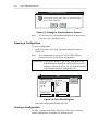
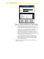
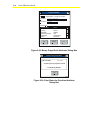
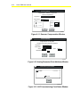
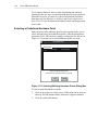
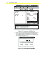
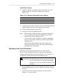
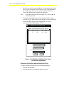
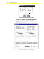
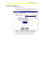
Using the Save As Option
To use the Save As option:
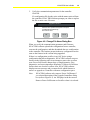
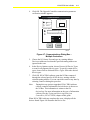
1.
On the File menu, click Save As. The Target Device Selection
dialog box appears (Figure 2-5).
2.
Select a device type (for example, Unitary Controller [UNT]). The
Devices list box displays the available devices for the selected
device type.
Note:
If you would like to save a configuration without generating
a download file, choose No Target Device from the Device
Type list.
Target Device Selection
Device Type: UNT
Devices:
UNT100-0
Devices Not Allowed:
UNT101-0
UNT110-0
Parameters
UNT110-1
UNT111-0
Parameters
UNT111-1
UNT120-0
UNT121-0
UNT120-1
UNT121-1
UNT140-1
UNT141-1
Device Description:
Unitary Controller: 6 AIs, 4 BIs (24 VAC), 8 BOs (High/Low Side Selectable).
N2 Isolation, Low Temp/High %RH Use.
OK
Cancel
SAVEAS
Figure 2-5: Target Device Selection Dialog Box
2-10
HVAC PRO User’s Guide
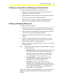
3.
Select a device from the Devices list box (for example,
UNT121-0).
When you highlight a device, a description of the device appears
in the Device Description box. If you select a device from the
Devices Not Allowed list, a dialog box similar to Figure 2-6
displays:
Target Device Selection
Device Type: UNT
Devices:
UNT100-0
Devices Not Allowed:
UNT101-0
UNT110-0
UNT111-0
UNT110-1
UNT111-1
UNT120-0
UNT121-0
UNT120-1
UNT121-1
UNT140-1
Device Description:
UNT141-1
Unitary Controller: 6 AIs, 4 BIs (24 VAC), 2AOs, 6 BOs
(High/Low Side Selectable). N2 Isolation, Low Temp/High %RH Use.
Reason Not Allowed:
The device UNT121-0 does not have enough real BOs.
OK
Cancel
SAVEAS3
Figure 2-6: Target Device Not Allowed
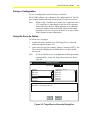
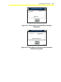
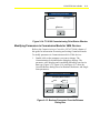
4.
Click OK with a valid device highlighted. The Save As dialog box
appears (Figure 2-7).
HVAC PRO User’s Guide
2-11
Save As
Filename:
Path:
c:\winpro\files
.cfg
Directories:
[..]
[-a-]
Parameters
[-b-]
[-c-]
[-i-]
[-m-]
[-u-]
[-y-]
OK
Cancel
SAVEAS2
Figure 2-7: Save As Dialog Box
5.
Type the desired path and/or file name. Click OK.
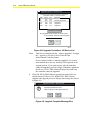
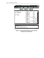
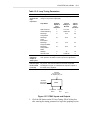
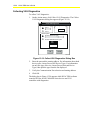
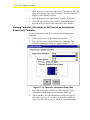
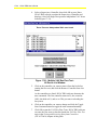
Note:
If you are saving a VAV application, and changes to the box
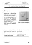
area, actuator stroke time, or target device affect the flow
tuning parameters, the Flow Tuning Parameters dialog box
appears (Figure 2-8). (This does not apply to the VMA.) This
dialog box displays the current value of the flow loop tuning
parameters (Prop Band, Integration Time, and Deadband)
and the calculated tuning parameter values for stable control.
2-12
HVAC PRO User’s Guide
Flow Tuning Parameters
Parameter
Current Value
-1600.00
Cold DK PropBand
16.00
Cold DK Integ Time
50.00
Cold DK Deadband
Calculated Value
-1582.00
16.40
42.00
-3616.00
16.40
96.00
-1600.00
16.00
50.00
Hot DK Prop Band
Hot DK Integ Time
Hot DK Deadband
Calculated tuning parameters do not match current
parameters. Do you want to use the calculated
values for these parameters?
100%
YES
NO
flwtun
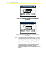
Figure 2-8: Flow Tuning Parameters Dialog Box
6.
Select either YES or NO.
•
YES saves the calculated tuning parameter values to the
configuration file (Figure 2-8).
•
NO retains the previous tuning values. The decision as to
which box tuning parameters to use is critical prior to box
download.
Notes:
Selecting size of deadband is discussed in the Testing and
Receiving Data from Controllers (LIT-63750416) chapter in
this guide.
Two sets of tuning parameters appear for Dual Duct
applications.
For information on the VMA1400 Series, refer to the
Variable Air Volume Modular Assembly (VMA) 1400 Series
Application Note (LIT-6375125).
Printing a Configuration
To print a configuration, on the File menu, click Print.
Changing the Print Format
To change the print format, on the File menu, click Print Format and
either Short or Long.
HVAC PRO User’s Guide
2-13
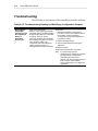
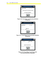
Troubleshooting
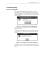
Saving a Configuration
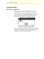
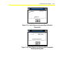
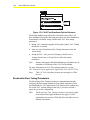
If the changes made to the configuration invalidate the currently
selected device, HVAC PRO software prompts you to make a new
device selection (Figure 2-9). For example, this occurs if more than
six Binary Outputs (BOs) are defined for a controller model that only
supports six BOs.
Johnson Controls - HVAC PRO
Changes to the configuration have invalidated
the current device.
Select OK to choose a new device.
OK
Cancel
INVALID
Figure 2-9: Invalid Device Selection Message Box
Click OK to select a new target device or Cancel to return to the
configuration process.
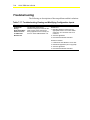
If the changes to the configuration use more controller memory than
available space, HVAC PRO software displays the following error
message:
File Save - Progress
This configuration contains errors.
Bidding Notepad to view the .ERR file.
OK
SAVERR
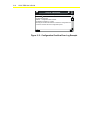
Figure 2-10: Configuration Overflow Error Message
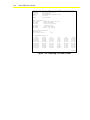
Click OK to view the error log (an example appears in Figure 2-11).
HVAC PRO software saves this error log in a file called configuration
name.err.
2-14
HVAC PRO User’s Guide
Notepad - VAV832.ERR
File
Edit
Search
Help
Configuration Overflow
ERROR -- Configuration Data Overflow.
Configuration overflow by 13 bytes.
Reconfigure and eliminate features to reduce the configuration size
or select a controller with more configuration space.
NOTEPAD
Figure 2-11: Configuration Overflow Error Log Example
HVAC PRO User’s Guide
3-1
Chapter 3
Downloading Configurations and
VMA Code
Introduction
The download configuration feature allows the user to download the
current, saved configuration to a controller or to multiple controllers.
Similarly, the download VMA code feature allows the user to
download updated controller firmware code into single or multiple
VMA1400 Series devices.
This chapter describes how to:
•
download the current configuration
•
download VMA code
© November 1, 2001 Johnson Controls, Inc.
Code No. LIT-63750404
www.johnsoncontrols.com
Software Release 8.03
3-2
HVAC PRO User’s Guide
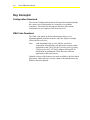
Key Concepts
Configuration Download
The Current Configuration option on the Download menu downloads
the current, saved configuration to a controller or to multiple
controllers. This menu selection appears dimmed if the current
configuration is not complete or has not been saved.
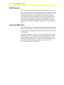
VMA Code Download
The VMA code option on the Download menu allows you to
download updated controller firmware code into single or multiple
VMA1400 Series devices.
Note:
Code downloads only over the N2 Bus, not from a
workstation. Downloading code deletes the current control
application in the VMA. See the Uploading and Upgrading
Configurations (LIT-63750405) chapter in this guide for
information on updating the VMA firmware code and
application in the same process.
Updated versions of the firmware are made available to the field when
appropriate. Older firmware versions cannot be downloaded once the
firmware has been updated.
HVAC PRO User’s Guide
3-3
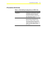
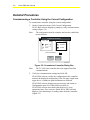
Procedure Overview
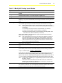
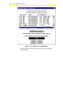
Table 3-1: Downloading Configurations and VMA Code
To Do This
Follow These Steps:
Download the Current
Configuration
On the Download menu, click Current
Configuration. Fill in the fields for a controller
on the N2 Bus. Verify the communication
selections and press Enter. Confirm the
selected device addresses. Select Cancel if
you need to change or add an address. Click
OK to download to the devices.
Download VMA Code
On the Download menu, click VMA Code.
Enter more than one N2 address in the
N2 Device Addresses field to download the
VMA code to multiple controllers. Verify the
communication selections and press Enter.
Confirm the selected device addresses. Select
Cancel if you need to change or add an
address. Click OK to download the VMA code
to the devices.
3-4
HVAC PRO User’s Guide
Detailed Procedures
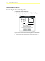
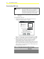
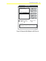
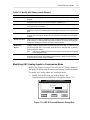
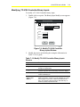
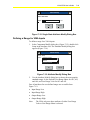
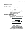
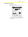
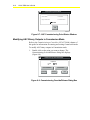
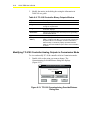
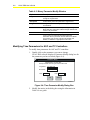
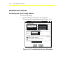
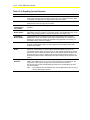
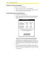
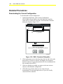
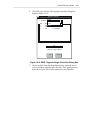
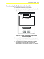
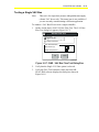
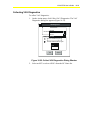
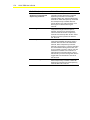
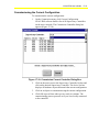
Downloading the Current Configuration
To download the current configuration:
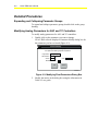
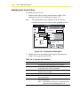
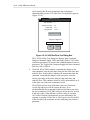
1.
On the Download menu, click Current Configuration. The
Download Controller dialog box for controllers on the N2 Bus
appears (Figure 3-1).
Download Controller
Bus Type
Comm. Port
Zone Bus
Port 1
N2 Bus
Port 2
Clear AI offsets?
N2 Device Addresses 1..8,12..16
0%
Select OK to begin download
N2 Addresses must be between 1 and 255
OK
Cancel
DOWNCO
Figure 3-1: Download Controller Dialog Box for the N2 Bus
2.
Fill in the fields for a controller on the N2 Bus using Table 3-2.
HVAC PRO User’s Guide
3-5
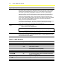
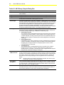
Table 3-2: Download Controller Fields for the N2 Bus
Option
Description
Communication Port and
Bus Type
Select the appropriate Communication Port and Bus Type. The
Communication Port and Bus Type default to the last entered value. The
N2 Device Addresses field defaults to the last entered single controller
address. HVAC PRO software does not save multiple N2 Device Addresses
as defaults.
Note:
The TC-9100 class controllers do not support Zone Bus
communications. If you select a TC-9100 controller as the target
device, the Zone Bus option appears dimmed.
Clear AI Offsets
Select or deselect the Clear AI Offsets option to clear Analog Input (AI) point
offsets for any Application Specific Controller (ASC), except the N2 Dialer
Module (NDM), when downloading over the Zone Bus. If you download
controllers over the N2 Bus or from a workstation, you cannot clear AI offsets
for UNTs or VAVs with firmware revisions earlier than D00 (2K controllers).
Note:
Clear AI offsets? appears dimmed when it is not available, and
it does not appear for TC-9100s, NDMs, or VMA1400 Series devices.
N2 Device Addresses
Enter more than one N2 address in the N2 Device Addresses field to
download multiple controllers. All N2 addresses must be within the range of
1 to 255. Use spaces between individual addresses and after commas, but
spaces cause errors if placed within a series specification.
HVAC PRO software uses the following formats:
•
Individual Addresses
1, 3, 7
1, 3, and 7
•
Range of Addresses
1..3
1 through 3
• Combination of Addresses 1..3,6..8
1 through 3 and 6 through 8
For TC-9100 controllers, refer to the TC-9102 Terminal Controller Technical
Bulletin (LIT-6363050) for instructions on how to set the controller address
switches.
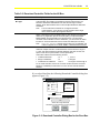
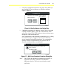
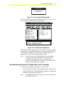
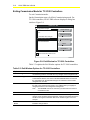
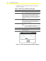
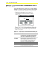
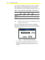
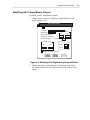
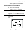
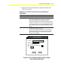
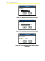
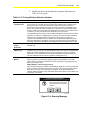
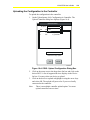
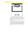
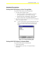
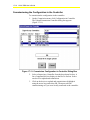
If you select Zone Bus, the following Download Controller dialog box
appears (Figure 3-2).
Download Controller
Bus Type
Comm. Port
Zone Bus
Port 1
N2 Bus
Port 2
Clear AI offsets?
N2 Device Addresses
Switches used to set device addresses
0%
Select OK to begin download
N2 Address (1-255) required if not using switches
OK
Cancel
DOWNCO2
Figure 3-2: Download Controller Dialog Box for the Zone Bus
3-6
HVAC PRO User’s Guide
3.
Fill in the fields for a controller on the Zone Bus using Table 3-3.
Table 3-3: Download Controller Options for the Zone Bus
Option
Description
Switches Used to Set
Device Addresses
This option is only available when you download an Air Handling Unit (AHU)
controller over the Zone Bus (Figure 3-2).
Some early versions of AHU controllers have no hardware switches. Their
controller address is stored in memory. Later versions of AHU controllers have
hardware switches, but retain the software address feature (you can address the
controller using hardware switches or software).
HVAC PRO software checks the addressing method of each AHU controller prior
to performing a download. HVAC PRO software uses the current addressing
method for the AHU controllers if you are using the N2 Bus. However if using the
Zone Bus, change the addressing method of any AHU controller with a firmware
revision later than BO1 by selecting or deselecting Switches Used to Set Device
Addresses.
Note: AHU controllers with firmware BO1 always must use a software address.
You cannot change the addressing method for these controllers.
Using a Software
Address for AHUs
Deselect the Switches Used to Set Device Addresses to set the N2 address in
software. Enter the device address in the N2 addresses edit field.
Using the Address
Switches for AHUs
Select the Switches Used to Set Device Addresses selection when you set the
N2 address using hardware switches. Set the device address using the hardware
switches on the controller. Refer to the Air Handling Unit (AHU) Controller
Technical Bulletin (LIT-6363010) for complete details on addressing the controller.
Note: HVAC PRO software displays a warning message if you select a different
addressing method than what the controller is currently using. You may
continue or return to the Download dialog box to reset the addressing
method.
Note:
Software addressing is also available for VMA1400 Series devices. See the Testing and Receiving
Data from Controllers chapter in this guide for details.
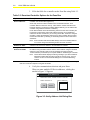
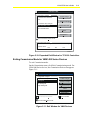
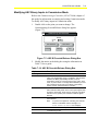
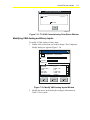
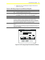
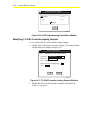
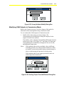
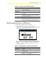
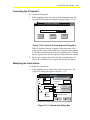
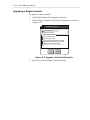
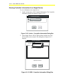
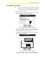
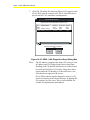
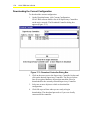
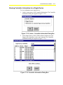
4.
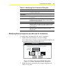
Verify the communication selections and press Enter.
When you enter multiple N2 Device addresses, a dialog box
similar to Figure 3-3 appears.
Verify Address List
Select OK to confirm, CANCEL to return to edit field.
Number of Devices: 6
OK
Cancel
Device Addresses
1
2
3
4
5
6
DOWNCNT2
Figure 3-3: Verify Address List Dialog Box
HVAC PRO User’s Guide
5.
3-7
Confirm the selected device addresses. Select Cancel if you need
to change or add an address. Click OK to download to the devices.
Notes:
For ASCs, HVAC PRO software shows you the progress
through the download process, waits for the controllers to
reset, and checks the controllers’ status. This ensures that
each controller is running a valid configuration.
For TC-9100 controllers, download skips the reset and status
check. For VMA1400 Series devices, download skips the
reset, but does check the status.
For HVAC PRO Release 7.02 and later, additional time is
added to the end of the VMA download process. This extra
time allows the controller to finish its internal archiving
process. This also applies to the VMA download that occurs
during the upgrade process.
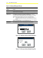
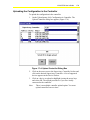
If you are downloading the configuration to multiple devices, a dialog
box similar to Figure 3-4 appears when the download is complete:
Download Controller
Download of multiple devices completed with
errors or warnings.
View Status Log File?
Yes
No
DOWNERR
Figure 3-4: Download Complete Dialog Box
This message prompts you to view the status log file regardless of
whether there were any download errors. Selecting Yes opens the file
in Windows Notepad. The status log lists device addresses and
information pertaining to the download process (for example, if the
download attempt was successful or if it failed). It also lists the reason
for download failure if it occurred. You can print the file from
Notepad. It is automatically saved as download.log.
Note:
Each time HVAC PRO software starts a multiple controller
download, it renames the existing download.log file to
download.nnn, where nnn is a number from 0 to 999.
3-8
HVAC PRO User’s Guide
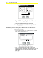
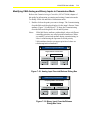
Downloading VMA Code
!
CAUTION:
Note:
All Analog Outputs (AOs) are zero during and
following a VMA code download until an
application is loaded into the controller. Be sure
to consider the impact this will have on your
system prior to performing a code download.
You must be directly connected to the N2 Bus to download
VMA code.
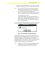
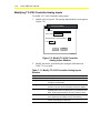
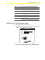
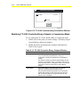
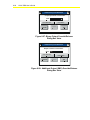
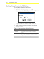
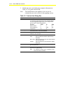
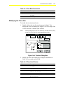
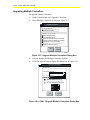
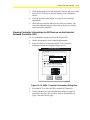
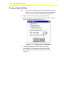
To download the VMA code:
1.
On the Download menu, select VMA Code (Version xxx).
A dialog box similar to Figure 3-5 appears:
Download Controller
Bus Type
Comm. Port
Zone Bus
Port 1
N2 Bus
Port 2
N2 Device Addresses
1..8,12..16
0%
Select OK to begin download
N2 Addresses must be between 1 and 255
OK
Cancel
DWNCOVMA
Figure 3-5: Download Controller Dialog Box for VMA
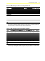
2.
Enter more than one N2 address in the N2 Device Addresses
field to download the VMA code to multiple controllers.
All N2 addresses must be within the range of 1 to 253
(Addresses 254 and 255 are reserved for the VMA). Use spaces
between individual addresses and after commas, but do not use
spaces within a series specification. HVAC PRO software uses
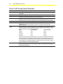
the formats shown in Table 3-4.
Table 3-4: Download Controller Address Formats
When Downloading To
This Format
Individual Addresses
1,3,7
1, 3, and 7
Range of Addresses
1..3
1 through 3
Combination of Addresses 1..3,6..8
Downloads To These
Addresses
1 through 3 and 6 through 8
HVAC PRO User’s Guide
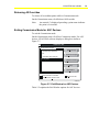
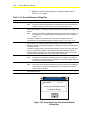
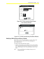
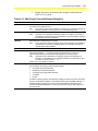
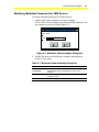
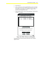
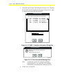
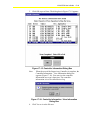
3.
3-9
Verify the communication selections and press Enter. When you
enter multiple N2 Device addresses, a dialog box similar to
Figure 3-6 appears.
Verify Address List
Select OK to confirm, CANCEL to return to edit field.
Device Addresses
1
2
3
4
5
6
Number of Devices: 6
OK
Cancel
DOWNCNT2
Figure 3-6: Verify Address List Dialog Box
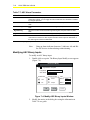
4.
Confirm the selected device addresses. Select Cancel if you need
to change or add an address. Click OK to download the VMA
code to the devices. HVAC PRO software shows you the progress
through the code download process.
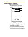
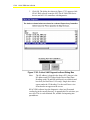
At the completion of code download for multiple devices, a dialog
box similar to Figure 3-7 appears. Select Yes to validate the
correct completion of multiple downloads. We recommend the
operator view the code download log file to ensure that all
controller code downloads were successful.
Download Controller
Download of multiple devices completed with
errors or warnings.
View Status Log File?
Yes
No
DOWNERR
Figure 3-7: VMA Code Download Complete Dialog Box
Note:
Once VMA code download is completed successfully, no
application exists in the controllers. Download the
application after the VMA code to perform the control
application.
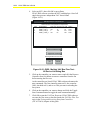
3-10
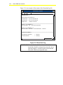
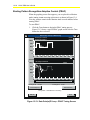
HVAC PRO User’s Guide
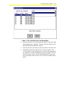
Figure 3-8 is an example of the content of the Download log file.
Download.log - Notepad
File
Edit
Search
Help
MULTIPLE CODE DOWNLOAD STATUS LOG
N2 Device Count: 2
Master Address for download is 13
Download Start:
Download End:
Elapsed Time:
Thu Jul 03 15:03:02 1997
Thu Jul 03 15:10:33 1997
7 minutes 31 seconds
DEVICE 1 (N2 ADDRESS 1)
Download Status: FAIL. . .Device never responded.
DEVICE 2 (N2 ADDRESS 13)
Download Status: SUCCESS. . .Code Download OK - No Errors.
DOWNLOAD SUMMARY:
SUCCESSFUL Downloads. . . . . 1
FAILED Downloads. . . . . . . . . . . 1
Device(s)
Device(s)
dwnldlog
Figure 3-8: Download Log
IMPORTANT: If a controller has failed in the download, further code
downloads should be attempted to ensure the device
operates properly. An unsuccessful code download
leaves the VMA in an inoperable state.
HVAC PRO User’s Guide
3-11
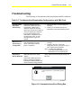
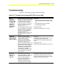
Troubleshooting
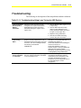
The following are descriptions of known problems and their solutions.
Table 3-5: Troubleshooting Downloading Configurations and VMA Code
Error/Condition
Problem
Solution
Communication
Error When
Downloading
During the download process,
HVAC PRO software checks the
configuration or VMA code to
determine whether the selected
device type matches the controller to
which it is attempting to download.
If HVAC PRO software cannot
download the configuration due to
communication errors, an error
message similar to Figure 3-9
appears.
1.
Device Type
Mismatch when
Downloading a
Configuration
If there is a device type mismatch
when downloading to a single
device, a dialog box similar to
Figure 3-10 appears.
1.
VMA Download
Failures over
Dial-Up Networks
HVAC PRO Release 7.02 fails to
download VMAs over a dial-up
network.
HVAC PRO software gets to 8%
before a message box appears
indicating the download failed. This
may be caused by timing problems.
Avoid attempting to download a VMA over a
dial-up network. Download directly through the
N2 trunk.
2.
Click the OK button to acknowledge the
message.
Check your connections and retry the
download or cancel the download process.
Click the OK button to acknowledge the
message.
2. Use File > Save As... to save the
configuration for the correct device type, or
enter a different device address.
Note: For VMA code downloads,
HVAC PRO software skips the code
downloads for any non-VMA device.
Download Controller
Communication error: Communication timeout
error.
OK
DOWNCOM
Figure 3-9: Communications Error Dialog Box
3-12
HVAC PRO User’s Guide
Download Controller
Download object was generated for an
incompatible device type.
OK
DOWNMISM2
Figure 3-10: Device Type Mismatch Dialog Box
HVAC PRO User’s Guide
4-1
Chapter 4
Uploading and Upgrading
Configurations
Introduction
Commands in the Upload menu allow the user to upload a
configuration in a controller or upgrade single or multiple controllers.
This chapter describes how to:
•
upload a configuration
•
upgrade a single controller
•
upgrade multiple controllers
© November 1, 2001 Johnson Controls, Inc.
Code No. LIT-63750405
www.johnsoncontrols.com
Software Release 8.03
4-2
HVAC PRO User’s Guide
Key Concepts
Automatic File Upgrade
When uploading a configuration in a controller, HVAC PRO software
compares the application and sideloop path revision numbers stored in
the controller with the revision numbers in the database. If the
configuration file used an earlier version of the application or sideloop
paths, HVAC PRO software prompts you to upgrade the file.
If the upgrade is optional, HVAC PRO software prompts the user to
continue without upgrade. If the user decides to continue without
upgrade, all Save and Save As commands produce download files of
the same application revision as are currently present in the controller.
If the user decides not to continue without upgrade by answering No to
the question, the application is upgraded to application revision in
HVAC PRO software. This allows the controller to continue to be
compatible with earlier revisions of HVAC PRO software. Note,
however, the format of the configuration file (.cfg) saved on the PC’s
hard drive may not be compatible with the earlier versions of
HVAC PRO software.
HVAC PRO software does not store changed point and parameter
names in the controller. When you upload a configuration, name
changes are lost. However, you can determine the configuration and
commission any controller downloaded with HVAC PRO software
without being required to know the configuration file name.
All controllers downloaded through HVAC PRO software support the
upload feature. The amount of information stored in an ASC device to
recreate the original configuration may, in rare cases, exceeds the
available space (this does not apply to the TC-9100 controller or the
VMA1400 Series device).
Upgrade Controllers Command
On the Upload menu, use the Upgrade Controllers command to
upgrade the configuration in a controller to the current release of
HVAC PRO software. The Upgrade Controllers dialog box appears
(Figure 4-1). You can upgrade most controllers on the N2 Bus from
any revision of HVAC PRO software.
HVAC PRO User’s Guide
!
4-3
WARNING: Upgrades cannot be guaranteed to work properly
unless the user runs the normal HVAC PRO icon
and performs a File > Open. Improper upgrades
can occur when the user associates a .cfg file with
hvacpro.exe and double-clicks on the .cfg file
icon. Improper upgrades can also occur if the
.cfg file is opened through the AIM Tool Project
File Manager.
Notes:
This feature is not available during Commission mode, and it
is not supported for TC-9100.
If the configuration in the controller currently uses an earlier
version of the application or sideloop paths,
HVAC PRO software displays a message telling you that a
newer version of the application exists and asks if you would
like to continue without an upgrade. Continuing without the
upgrade allows the upload process to continue as normal. If,
however, you decide to not continue with the upgrade, the
upload process is aborted. At this point, you will need to
manually upgrade the application and continue an upload
following a successful upgrade.
Upgrade Controllers
Type of Upgrade
Single Controller
Multiple Controllers
Multiple Controller Options
Save Uploaded Object
Log Parameter Values
Only Check Config Size (No Download)
Remove Power Fail Restart on Overflow
Update VAV Tuning Parameters
Download VMA Code (non-OWS only)
Replace CFG Files on Disk
OK
Cancel
UPVAV2
Figure 4-1: Upgrade Multiple Controllers Dialog Box
Select Single Controller to upgrade one specific device or select
Multiple Controllers to upgrade more than one device on the N2 Bus.
These options are described in more detail in the following section
called Upgrade Controller Options.
4-4
HVAC PRO User’s Guide
Upgrade Controller Options
Table 4-1 explains the different options in the Upgrade Controllers
dialog box (Figure 4-1).
Table 4-1: Upgrade Controller Options
Option
Description
Save Uploaded Object
When you select Save Uploaded Object, HVAC PRO software saves the uploaded
object file from an ASC device to the currently selected directory. The file names
are listed in Table 4-2.
Log Parameter Values
When you select Log Parameter Values, HVAC PRO software logs all parameter
values to a file located in the directory specified by the FILES path. The values are
logged before the upgrade updates them. The parameter log file name varies with
the control application. For example, the parameters for a Single Duct VAV
application are logged to the file sdparms.log. HVAC PRO software appends this
file each time you upgrade a controller with this option selected.
This is a tab separated file with the parameter names, parameter values, and
controller N2 address (or ZB if the upgrade is done on the Zone Bus). You can
import this file directly into Excel or any other third-party package that accepts
tab-delimited files. This can be very valuable for record keeping and documentation
purposes.
Only Check Config
Size (No Download)
When you select Only Check Config Size (No Download), HVAC PRO software
performs the complete upgrade except for the last step of downloading the
controller. This is a quick way to get configuration information and parameter
values without affecting the controller.
Remove Power Fail
Restart on Overflow
When you select Remove Power Fail Restart on Overflow, HVAC PRO software
can remove the Power Fail Restart feature from an ASC configuration if the
configuration conversion results in the overflow of available controller configuration
space. HVAC PRO software may require more configuration space due to
enhanced strategies. Refer to Upgrading a Single Controller in the Detailed
Procedures section for further information on Power Fail Restart.
Update VAV Tuning
Parameters
When you select Update VAV Tuning Parameters, HVAC PRO software
recalculates and updates the VAV tuning parameters for applications loaded in a
VAV controller. Deselect this option to retain the current tuning parameter values.
Download VMA Code
When you select Download VMA Code, HVAC PRO software updates the VMA
firmware by downloading the firmware code to the device as part of the upgrade
process. If you select this option, HVAC PRO software uploads the VMA’s
configuration data, creates the upgraded configuration and download files,
upgrades the firmware code in the device, and downloads the upgraded
application.
Notes: When performing a multiple controller upgrade with code download on
VMA1400 Series controllers, it is important to consider the amount of time
the VMAs will be inoperable. This time can be estimated using the
following formula:
Inoperable Time = (2 minutes * number of controllers) + 10 minutes
We recommend upgrading multiple VMAs in quantities that will not allow
the zone served by the VMAs to drift away from setpoint by more than
what is acceptable to the customer.
Replace CFG Files on
Disk
During multiple controller uploads, you do not want to constantly interrupt the
upgrade process to supply configuration file names. Replace CFG Files on Disk
gives you control of either replacing any matching names or not writing a
configuration file if one already exists with the same name.
Note:
The Replace CFG Files on Disk selection is only available when Multiple
Controllers is selected.
HVAC PRO User’s Guide
Table 4-2: HVAC PRO Object File Names
HVAC PRO Versions
File Name
DOS-based Versions
AHUnnn.AHO*
UNTnnn.UCO*
VAVnnn.VAO*
Windows-based Versions
XXXnnn.ASC*
*
XXX is the controller type (AHU, NDM, VAV, UNT, or PHX) and nnn is the
controller’s N2 address or Zone Bus (ZB).
Note:
HVAC PRO software does not support an upgrade of the TC-9100.
4-5
4-6
HVAC PRO User’s Guide
Procedure Overview
Table 4-3: Uploading and Upgrading Configurations
To Do This
Follow These Steps:
Upload a Configuration
On the Upload menu, click Configuration in
Controller. Verify the communication
selections and click OK.
Upgrade a Single Controller
On the Upload menu, click Upgrade
Controllers. In the Upgrade Controllers dialog
box, select Single Controller. Select/deselect
the options. Click OK. In the Upgrade
Controller communication parameter
verification window, verify the communication
parameters for the controller. Click OK.
Upgrade Multiple Controllers
On the Upload menu, click Upgrade
Controllers. Select Multiple Controller.
Select/deselect the options. Click OK. In the
Upgrade Controller communication parameter
verification window, choose the N2 Comm.
Port and type in a starting address. In the
Device Options section, choose Process All
Device Types to scan for all supported device
types. To specify certain device types, choose
Process Selected Device Types. Select the
types. Click OK.
HVAC PRO User’s Guide
4-7
Detailed Procedures
Uploading a Configuration
To upload a configuration:
1.
On the Upload menu, click Configuration in Controller. The
Upload Controller dialog box appears (Figure 4-2). The
Communication Port, Bus Type, and N2 Device Address all
default to the last entered value.
Upload Controller
Bus Type
Comm. Port
Port 1
Zone Bus
Port 2
N2 Bus
N2 Device Address
0%
Select OK to begin upload
OK
Cancel
UPCONT
Figure 4-2: Upload Controller Dialog Box
2.
Verify the communication selections and click OK.
HVAC PRO software uploads the object file from the controller
and rebuilds the configuration. HVAC PRO software shows the
progress through the upload process.
4-8
HVAC PRO User’s Guide
Upgrading a Single Controller
To upgrade a single controller:
1.
On the Upload menu, click Upgrade Controllers. The Upgrade
Controllers dialog box appears (Figure 4-3).
Upgrade Controllers
Type of Upgrade
SingleController
Multiple Controllers
Single Controller Options
Save Uploaded Object
Log Parameter Values
Only Check Config Size (No Download)
Remove Power Fail Restart on Overflow
Update VAV Tuning Parameters
Download VMA Code (Version xxx)
OK
Cancel
UPVAV
Figure 4-3: Upgrade Controllers Dialog Box
2.
Select Single Controller.
3.
Select/deselect the options. The options are described in
Table 4-1.
4.
Click OK. The Upgrade Controller communication parameter
verification window appears (Figure 4-4).
Upgrade Controller
Comm. Port
Bus Type
Port 1
Zone Bus
Port 2
N2 Bus
N2 Device Address
4
0%
Select OK to begin Upgrade
OK
Cancel
UPGRADE
Figure 4-4: Communication Parameter Verification Window
HVAC PRO User’s Guide
5.
4-9
Verify the communication parameters for the controller.
Click OK.
If a configuration file already exists with the name retrieved from
the controller, HVAC PRO software prompts you either to replace
the file or enter a new file name.
Upgrade Controllers
File-Save of the Uploaded Configuration will replace
C:\WINPRO\FILES\VAV832.cfg.
Enter new file name?
Yes
No
Cancel
UPGRADE2
Figure 4-5: Change File Name Dialog Box
When you verify the communication parameters and file name,
HVAC PRO software uploads the configuration from a controller,
converts the configuration, and then downloads the new configuration
to the controller. The features present in the new configuration are the
same as the features in the version being upgraded.
If there is a configuration overflow in an ASC device using a
configuration that allows diagnostics, HVAC PRO software removes
features in the following order in an attempt to remove the overflow
error: Power Fail Restart, damper duty cycling diagnostics, flow
diagnostics, and zone temperature diagnostics. If removal of all these
features does not clear the overflow error, HVAC PRO software
displays an error message and you must decide which features to
remove or upgrade to a controller with more configuration space.
Note:
HVAC PRO software only removes Power Fail Restart if
you selected that option in the Upgrade Controllers dialog
box (refer to Figure 4-3). An X displays in the box next to
Remove Power Fail Restart on Overflow when it is selected.
4-10
HVAC PRO User’s Guide
Upgrading Multiple Controllers
To upgrade multiple controllers:
1.
On the Upload menu, click Upgrade Controllers. The Upgrade
Controllers dialog box appears (Figure 4-6).
Upgrade Controllers
Type of Upgrade
Single Controller
Multiple Controllers
Multiple Controller Options
Save Uploaded Object
Log Parameter Values
Only Check Config Size (No Download)
Remove Power Fail Restart on Overflow
Update VAV Tuning Parameters
Download VMA Code (non-OWS only)
Replace CFG Files on Disk
OK
Cancel
UPVAV2
Figure 4-6: Upgrade Multiple Controllers Dialog Box
2.
Select Multiple Controllers.
3.
Select/deselect the options. The options are described in
Table 4-1.
HVAC PRO User’s Guide
4.
4-11
Click OK. The Upgrade Controller communication parameter
verification window appears.
Upgrade Controllers
N2 Comm. Port
Starting Address
Port 1
Parameters
1
Port 2
Devices Options
Process All Device Types
Process Selected Device Types:
AHU
UNT
VAV
PHX
OK
Cancel
UPASCS
Figure 4-7: Communications Dialog Box –
Multiple Controllers
5.
Choose the N2 Comm. Port and type in a starting address.
Devices at addresses less than the specified starting address are
ignored in the scan.
6.
In the Device Options section, choose Process All Device Types
to scan for all supported device types. To specify certain device
types, choose Process Selected Device Types. Select the desired
device types.
7.
Click OK. HVAC PRO software scans the N2 Bus connected
through the selected port for all N2 devices, starting with the
selected starting address. You can cancel the search at any time by
selecting Cancel or hitting the space bar.
Note:
During this scan (prior to upgrades) HVAC PRO software
collects controller information for each device it detects on
the N2 Bus. This information is written to the file
devices.log. For more information on the type of information
collected, see the Testing and Receiving Data from
Controllers (LIT-63750416) chapter in this guide.
When HVAC PRO software completes the scan, it displays all the
devices found. Figure 4-8 illustrates the Device list.
4-12
HVAC PRO User’s Guide
Upgrade Controllers - N2 Device List
The devices shown below were found on the N2 Bus.
All devices marked ">" will be processed.
Addr
Device Rev.
Application
Single Duct
VAV
>2
4.00
Mixed Air Single Path
AHU
#3
3.04
Single Duct
VAV
>18
4.00
Single Duct
VMA 7.00
>25
Single Duct
VAV
>235
5.10
Mark/Unmark Controller
Non-upgradable devices (marked "#") will be ignored.
Scan Completed - Select OK to begin Upgrades
100%
OK
Cancel
UPVAV3
Figure 4-8: Upgrade Controllers - N2 Device List
Notes:
Only devices marked with the > sign are upgraded. To toggle
the > sign on or off, select a device and click the
Mark/Unmark Controller button.
Devices marked with a # cannot be upgraded. You cannot
mark/unmark these devices, and they will be ignored in the
upgrade process. If you want to know why the controller
cannot be upgraded, perform a Single Controller Upgrade for
that device. HVAC PRO software displays the reason why
the controller cannot be upgraded.
8.
Click OK. HVAC PRO software upgrades the marked devices
included in the N2 Device List. When HVAC PRO software
completes the upgrade process it displays the message box shown
in Figure 4-9.
Upgrade Controllers -- N2 Device List
Upgrades completed with 0 errors.
Would you like to view the upgrade status log?
Yes
No
UPVAV4
Figure 4-9: Upgrade Complete Message Box
HVAC PRO User’s Guide
4-13
HVAC PRO software writes a detailed upgrade summary for each
device. This summary, called upgrade.log, is stored in the current
directory. This upgrade log includes information such as whether there
were errors in the upgrade process. It also indicates where files are
stored. If a recovery action is required for a failed upgrade, the log file
lists the necessary steps involved. Select Yes to view the upgrade log.
Note:
When HVAC PRO software writes an upgrade summary, it
renames the existing upgrade.log file to upgrade.nnn, where
nnn is a number from 0 to 999.
4-14
HVAC PRO User’s Guide
Troubleshooting
Uploading a Configuration
If the available space is exceeded during the File > Save process,
HVAC PRO software warns it cannot upload the configuration.
If HVAC PRO software cannot upload the configuration because of
communications errors, an error message similar to the Figure 4-10
appears. (A different message appears if the controller cannot be
uploaded.) Click the OK button to acknowledge the message.
Upload Controller
Communications error: Communication timeout
error
OK
UPERR
Figure 4-10: Upload Error Dialog Box
Check the port and bus type, check the N2 address if you are using an
N2 Bus, and restart the upload process. Click OK to continue when the
upload process completes. Save the uploaded configuration by
selecting Save or Save As through the File menu.
HVAC PRO User’s Guide
5-1
Chapter 5
Commissioning a Controller
Introduction
Commissioning a controller takes place in Commission mode, a mode
allowing online, operating communications with the controller.
This chapter describes how to:
•
commission a controller using the current configuration
•
commission using the configuration in the controller
•
calibrate sensors using the AI Offset Table for ASC devices
•
release all overrides
•
exit Commission mode for ASC devices
•
exit Commission mode for TC-9100 controllers
•
exit Commission mode for VMA1400 Series devices
•
reset a controller
© November 1, 2001 Johnson Controls, Inc.
Code No. LIT-63750406
www.johnsoncontrols.com
Software Release 8.03
5-2
HVAC PRO User’s Guide
Key Concepts
Commission Mode
The Commission mode allows online, operating communications with
the controller.
Commission Using the Configuration in the Controller
ASC Devices
When commissioning using the configuration in the controller for
ASC devices, HVAC PRO software compares the application and
sideloop path revision numbers stored in the controller with the
revision numbers in the database.
If the configuration in the controller used an earlier version of the
application or sideloop paths, HVAC PRO software displays a
message telling you that a newer version of the application exists and
asks if you would like to continue without an upgrade.
If you do not continue, the commissioning process is aborted. You
must manually upgrade the application and continue to commission
after the successful upgrade.
If you choose to continue without an upgrade, HVAC PRO software
checks the file name of the configuration in the controller and looks
for a matching name in the current directory set by
HVAC PRO software. It also checks for matching device types,
application names, and application/sideloop data versions. When a
matching file exists, a dialog box asks to use it for commissioning
(Figure 5-1).
Upload/Commission Controller
The configuration in the controller may match the
configuration in the file
c:\winpro\files\vav832.cfg.
Read configuration from FILE?
Yes
No
Cancel
UPCOM
Figure 5-1: Read Configuration from File Dialog Box
If you select No, HVAC PRO software uploads the configuration from
the controller and starts the Commission mode. If you select Cancel,
the process is aborted. If you select Yes, HVAC PRO software reads
the configuration from the file and starts commissioning.
HVAC PRO User’s Guide
5-3
TC-9100 Controllers and VMA Devices
When commissioning using the configuration in the controller for both
TC-9100 controllers and VMA1400 Series devices,
HVAC PRO software performs a single controller upload as described
in the Uploading and Upgrading Configurations (LIT-63750405)
chapter in this guide.
Exiting Commission Mode in TC-9100 Controllers and
VMA1400 Series Devices
The Commission Exit dialog box for TC-9100 controllers lists all
parameters that have differences between the configuration value, the
EEPROM value at the start of the commissioning session, and/or the
current EEPROM value. Overridden points are not listed, and all
overrides will be released when HVAC PRO software returns to the
Configuration mode.
The Commission Exit dialog box for VMA1400 Series devices lists all
application components that have configurable attributes or parameters
with differences between their configuration value, their controller
value at the start of the commissioning session, and/or their current
controller value.
Sensor Calibration in Using the AI Offset Table for ASC Devices
This function is available for ASC devices only. This function allows
you to calibrate sensors by adding or subtracting from the present
sensor reading to eliminate any error due to wire length or sensor drift.
It is only available when you are in Commission mode. In other
modes, this menu item is unavailable.
Note:
If you are commissioning a 2K controller or AHU over the
N2 Bus, you can only view the AI offsets. You will not be
able to calibrate them. A warning message in the AI Offset
Table alerts you of this condition. (You can adjust offsets
over the N2 Bus for 8K controllers over the Zone Bus for
any application specific controller.)
You can only adjust the offset of an AI point when you are online with
the controller during commissioning. The offset value is maintained in
the EEPROM of the controller. Auto Zero mode, if enabled,
automatically calculates and adjusts the offset value for the velocity
pressure transducer used in VAV terminal unit controllers.
Override Release in Commission Mode
This Commission menu option activates when you override any points
while in Commission mode. Select this menu option to release all
overridden points.
5-4
HVAC PRO User’s Guide
Controller Resetting
The Reset Controller feature allows you to reset a single ASC or
VMA1400 Series device without entering the Commission mode.
TC-9100 controllers do not process the reset command.
HVAC PRO User’s Guide
5-5
Procedure Overview
Table 5-1: Commissioning a Controller
To Do This
Follow These Steps:
Commission a Controller
Using the Current
Configuration
On the Commission menu, click Current
Configuration. Verify the communications
settings and click OK. HVAC PRO software
enters the Commission mode.
HVAC PRO software displays the current
states of the inputs, outputs, and parameters.
Commission Using the
Configuration in the Controller
On the Commission menu, click Configuration
in Controller. Verify the communication
parameters and click OK.
Calibrate Sensors Using the AI
Offset Table for ASC Devices
On the Commission menu, click AI Offset
Table. View, or if allowed, modify and save the
AI offsets to the controller. To modify the AI
Offset values, select the AI point you want to
change. Click in the Edit field. Type in the
desired offset value. Repeat steps to adjust
other offsets. When you are finished, click OK.
Release All Overrides
On the Commission menu, click Release All
Overrides.
Exit Commission Mode for
ASC Devices
On the Commission menu, click Exit
Commissioning Mode. Select the appropriate
options.
Exit Commission Mode for
TC-9100 Controllers
On the Commission menu, click Exit
Commissioning Mode. Select the appropriate
options.
Exit Commission Mode for
VMA1400 Series Devices
On the Commission menu, click Exit
Commissioning Mode. Select the appropriate
options.
Reset a Controller
On the Action menu, click Reset Controller.
Select the proper communication settings for
the controller to be reset. Click OK to reset the
controller or Cancel to abort the operation.
5-6
HVAC PRO User’s Guide
Detailed Procedures
Commissioning a Controller Using the Current Configuration
To commission a controller using the current configuration:
1.
On the Commission menu, click Current Configuration.
HVAC PRO software displays a prompt to verify communications
settings (Figure 5-2).
Note:
The configuration must be complete and saved to enable this
menu selection.
Commission Controller
Comm. Port
Bus Type
Port 1
Zone Bus
Port 2
N2 Bus
N2 Device Address
OK
4
Cancel
COMCONT2
Figure 5-2: Commission Controller Dialog Box
Note:
2.
The TC-9100 class controller does not support Zone Bus
communications.
Verify the communications settings and click OK.
HVAC PRO software verifies the configuration in the controller
matches the displayed configuration. If the file name, application,
target device, or hardware point definitions are different,
HVAC PRO software displays an error message and returns to
Configuration mode. For VMA1400 Series devices,
HVAC PRO software also checks that the device is in an
operational state. If no errors are found, HVAC PRO software
displays a box indicating it is reading values from the controller
(Figure 5-3).
HVAC PRO User’s Guide
5-7
Commissioning
Currently accessing data.
Please Wait...
ACCDATA
Figure 5-3: Accessing Data Dialog Box
HVAC PRO software enters the Commission mode. You can view all
values after HVAC PRO software obtains them.
Johnson Controls -HVAC PRO -Commissioning
File Download Upload Commission Action Options Help
Q/A
INPUTS
Parameters
Modes
Occupied Status Occpd
Starved Box
No
Warmup CommandOff
Summer/Winter Winter Minute
Restart Delay
0.0
Restart Status
Off
Shutdown Status Off Minute
Occ Ovrd Time
0.0
Temp Occ Status Off
Zone Cooling Setpoints
Occ Clg Setpt
72.0 Deg F
Stby Clg Setpt
74.0 Deg F
Unocc Clg Setpt 80.0 Deg F
Clg Prop Band
2.0 Deg F
Date: 05/21/94
OUTPUTS
PARAMS
SIDELOOP
Inputs
Analog Inputs
*AI 1 Zone Temp 72.00 Deg F
Binary Inputs
Occ
BI 2 Standby
Off
BI 3 Shutdn Box O... Off
!BI 4 Shutdn Box Cl... Off
Accumulator: 0
* BI 1 Occupied
N2 Address: 4
Time: 7:32:32 AM
Device Type: VAV-VAV101-0
Application: VAV Applications - Single Duct
Filename: c:\winpro\files\vav832.cfg
commiss
Figure 5-4: Commissioning Window
HVAC PRO software displays the current states of the inputs, outputs,
and parameters. An asterisk displays next to points or parameters that
are currently overridden. For ASC devices, an alarm indicator (!)
displays next to AIs or Binary Inputs (BIs) in alarm.
Note:
For ASC devices, the override indicator (*) has a higher
precedence than the alarm indicator (!). If the point is
overridden into alarm, then the override indicator (*)
displays. Once the point’s override is released while still in
alarm, the alarm indicator (!) displays.
Commissioning Using the Configuration in the Controller
To commission using the configuration in the controller:
1.
On the Commission menu, click Configuration in Controller. The
Upload/Commission Controller dialog box appears requesting the
communication parameters (Figure 5-5).
Note:
The upload feature supports only devices downloaded with
HVAC PRO software.
5-8
HVAC PRO User’s Guide
Upload/Commission Controller
Comm. Port
Bus Type
Port 1
Zone Bus
Port 2
N2 Bus
N2 Device Address
4
0%
Select OK to begin upload
OK
Cancel
COMCONT1
Figure 5-5: Commission Configuration in Controller
Dialog Box
2.
Verify the communication parameters and click OK.
Note:
The TC-9100 class controller does not support Zone Bus
communications.
Calibrating Sensors Using the AI Offset Table for ASC Devices
To enter the AI Offset mode:
1.
On the Commission menu, click AI Offset Table. The AI Offset
Table window appears (Figure 5-6).
AI Offset Table
Analog Input Points
AI1 Zone Temp
0.00
AI2 Cooling Setpoint 0.00
AI3 Heating Setpoint 0.00
AI1 Offset Value
0.00
AI Offsets from N2 Bus can only be viewed!
OK
Cancel
OFFSET2
Figure 5-6: AI Offset Table Window
2.
View, or if allowed, modify and save the AI offsets to the
controller. To modify the AI Offset values, select the AI point you
want to change, click in the Edit field, and type in the desired
offset value.
3.
Click OK.
HVAC PRO User’s Guide
5-9
Releasing All Overrides
To release all overridden points while in Commission mode:
On the Commission menu, click Release All Overrides.
Note:
An asterisk (*) displayed preceding a point name indicates
the point is in override.
Exiting Commission Mode for ASC Devices
To exit the Commission mode:
On the Commission menu, click Exit Commission mode. For ASC
devices, HVAC PRO software displays a dialog box similar to
Figure 5-7.
Commission Exit
Configuration Changes
Hardware Point Attributes
Exit/No Change
None...
Exit/Save Changes
Parameter Value Changes
*Occ Clg Setpt
Remove Override
Cancel
View Details>>
Save Overrides to Controller
Reset Controller
Save Controller Values to File
COMEXIT3
Figure 5-7: Exit Window for ASC Devices
Table 5-2 explains the Exit Window options for ASC devices.
5-10
HVAC PRO User’s Guide
Table 5-2: Exit Window Options for ASC Devices
Option
Description
Exit/No Change
Does not save overrides to the controller or controller values to the
configuration file.
Exit/Save Changes
Saves overrides and controller values according to the selected options. Only
available when there have been changes to the configuration.
Remove Override
Removes individual overrides from the Configuration Changes list.
Cancel
Closes the Commission Exit window and returns to the Commission mode.
View Details
Expands the Commission Exit window and views details of configuration
changes. Refer to Figure 5-8 for an example.
Save Overrides to
Controller
Saves the override values to the controller. You do not need to download the
controller again. These new values become the current controller values.
Note:
When you select both Save Controller Values to File and Save
Overrides to Controller, HVAC PRO software saves the overrides first
then the controller values (now the override values) to the
Configuration file.
Save Controller Values to
File
Saves current controller values to the Configuration file when you press the
Exit/Save Changes button.
Reset Controller
Sends a reset command to the controller as it exits Commission mode. Most
controllers come back online to the N2 Bus after a 10-minute delay following
Zone Bus communications. However, the controllers listed below do not have
this feature and require a controller reset after Zone Bus communications to
enable N2 Bus communications. If you do not reset these controllers, they will
not come back online to the N2 Bus. HVAC PRO software displays a reminder
with an option to reset the controller after it communicates over the Zone Bus
with any of the following: AHU (Firmware Version B01), UNT (Firmware
Version A01), VAV (Firmware Version A01).
Refer to the Testing and Receiving Data from Controllers (LIT-63750416)
chapter in this guide for information on obtaining the controller type and its
firmware revision. When you exit commissioning, all overrides not saved to the
controller are released, and HVAC PRO software returns to the main display.
HVAC PRO User’s Guide
Commission Exit
Configuration Changes
Exit/No Change
Hardware Point Attributes
None...
Exit/Save Changes
Parameter Value Changes
*Occ Clg Setpt
Remove Override
Cancel
View Details<<
Save Overrides to Controller
Reset Controller
Save Controller Values to File
*Occ Clg Setpt
Parameter Value
Config
Controller
Override
72.0
72.0
74.0
COMEXIT2
Figure 5-8: Expanded Exit Window for ASC Devices
5-11
5-12
HVAC PRO User’s Guide
Exiting Commission Mode for TC-9100 Controllers
To exit Commission mode:
On the Commission menu, click Exit Commissioning mode. For
TC-9100 controllers, HVAC PRO software displays a dialog box
similar to Figure 5-9:
Commission Exit
Configuration Changes
Hardware Point Attributes
Exit/No Change
None...
Exit/Save Changes
Parameter Value Changes
Room Temp Filter Const.
Remote SP Filter Const.
Fan On/Off Differential
Restore EE2 Value
Cancel
View Details>>
Save Current EE2 Values to File
COMEXIT4
Figure 5-9: Exit Window for TC-9100 Controllers
Table 5-3 explains the Exit Window options for TC-9100 controllers.
Table 5-3: Exit Window Options for TC-9100 Controllers
Option
Description
Exit/No Change
Restores all controller EEPROM values changed during the current
commissioning session. Does not save any changes to the Configuration file.
Exit/Save Changes
Restores any controller EEPROM values selected to restore. Then, if Save
Current EE2 is selected, the current controller EEPROM values are saved to
the configuration file. All EEPROM changes not selected to restore remain
changed in the controller.
Restore EE2 Value
Restores the controller’s EEPROM value for a parameter to the value it held at
the start of the commissioning session. Only enabled when you highlight a
changed parameter in the Configuration Changes list.
Note:
The EEPROM value is not restored if you select Cancel to return to
Commission mode.
Cancel
Closes the Commission Exit window and returns to the Commission mode.
View Details
Expands the Commission Exit window and shows details of configuration
changes. If the window is already expanded, selecting View Details returns the
window to the regular Commission Exit screen. Refer to Figure 5-10 for an
example.
Save Current EE2 Values
to File
Saves current controller values to the Configuration file when you press the
Exit/Save Changes button.
HVAC PRO User’s Guide
5-13
Commission Exit
Configuration Changes
Exit/No Change
Hardware Point Attributes
None...
Exit/Save Changes
Parameter Value Changes
Room Temp Filter Const.
Remote SP Filter Const.
Fan On/Off Differential
Restore EE2 Value
Cancel
View Details<<
Save Current EE2 Values to File
Room Temp Filter Const.
Config
Parameter Value
10.0
EE2 Start
EE2 Change
10.0
15.0
COMEXIT5
Figure 5-10: Expanded Exit Window for TC-9100 Controllers
Exiting Commission Mode for VMA1400 Series Devices
To exit Commission mode:
On the Commission menu, click Exit Commissioning mode. For
VMA1400 Series devices, the Commission Exit screen appears
Figure 5-11.
Commission Exit
Configuration Changes
Application Components
Cooling PID
Flow Control.Flow Controller
Box Heating PID
Suppl Heating PID
Exit/No Changes
Exit/Save Changes
Remove Change
Cancel
View Details>>
Save Changes to Controller
Reset Controller
Save Controller Values to File
comexit6
Figure 5-11: Exit Window for VMA Devices
5-14
HVAC PRO User’s Guide
Table 5-4 explains the Exit Window options for VMA1400 Series
devices.
Note:
For Exit/Save Changes, the hourglass icon displays while
VMA archive is in progress (less than 60 seconds).
Table 5-4: Exit Window Options for VMA Devices
Option
Description
Exit/No Change
Restores all controller changes made during the current commissioning
session. This option does not save any changes to the configuration file.
Exit/Save Changes
Saves overrides and controller values according to the options you have
selected. (Refer to Save Changes to Controller and Save Controller Values to
File in this table.) This option is only enabled when there have been changes
to the configuration.
Remove Change
Removes individual changes for attributes or parameters of an application
component. This option is only enabled when a changed item is selected on
the expanded Exit Commission window.
Cancel
Closes the Commission Exit window and returns to the Commission mode.
View Details
Expands the Commission Exit window and shows details of configuration
changes. If the window is already expanded, selecting View Details returns the
window to the regular Commission Exit screen. The details show all
configurable attributes and parameters that have differences between the
configuration and controller values. Refer to Figure 5-12.
Save Changes to
Controller*
Saves all the changed values displayed in an application component’s details
list to the controller when you press the Exit/Save Changes button. You do not
need to download the controller again. These new values become the current
controller values.
Notes: When you select both Save Controller Values to File and Save
Changes to Controller, HVAC PRO software saves the changes first,
then the controller values (now the changed values) to the
Configuration file.
The Proportional Band and Integral Time for the Zone Temperature
control loops (cooling and proportional heating) are automatically
updated by the VMA’s internal Pattern Recognition Adaptive Control
(PRAC) algorithm. If these values have not been permanently saved
to the configuration file, they show up as changes in the Commission
Exit dialog box. If you wish to ensure that the tuned values are used
in future application downloads to the VMA, select the option to Save
Controller Values to File, and use the Exit/Save Changes button to
exit.
Save Controller Values to
File**
Saves current controller values to the Configuration file when you press the
Exit/Save Changes button.
Reset Controller
Sends a reset command to the controller as it exits Commission mode.
*
**
Save Changes to Controller keeps the application version the same and changes the
HVAC PRO version.
When you exit commissioning with the option to save controller values to file, HVAC PRO software
produces a download file of the same application version currently present in the controller. This allows
the controller to continue to be compatible with earlier versions of HVAC PRO software. However the
format of the configuration files (.cfg) generated by these saves may not be compatible with earlier
versions of HVAC PRO software.
HVAC PRO User’s Guide
5-15
Commission Exit
Configuration Changes
Exit/No Changes
Application Components
Cooling PID
Flow Control.Flow Controller
Box Heating PID
Suppl Heating PID
Exit/Save Changes
Remove Change
Cancel
View Details<<
Save Changes to Controller
Reset Controller
Save Controller Values to File
Cooling PID
Config
0
Setpoint
Controller
72
Change
comexit7
Figure 5-12: Expanded Exit Window for VMA Devices
Resetting a Controller
To reset a controller:
1.
On the Action menu, click Reset Controller. The Reset Controller
dialog box displays (Figure 5-13).
Reset Controller
Comm. Port
Bus Type
Port 1
Zone Bus
Port 2
N2 Bus
N2 Device Address
OK
255
Cancel
RSETCONT
Figure 5-13: Reset Controller Dialog Box
2.
Select the proper communication settings for the controller to be
reset.
5-16
HVAC PRO User’s Guide
3.
Click OK to reset the controller or Cancel to abort the operation.
HVAC PRO User’s Guide
6-1
Chapter 6
Viewing and Modifying
Configurations
Introduction
The Question/Answer session, accessed by clicking the Q/A button,
provides the means to modify an existing configuration.
This chapter describes how to:
•
view a configuration
•
modify a configuration
© November 1, 2001 Johnson Controls, Inc.
Code No. LIT-63750407
www.johnsoncontrols.com
Software Release 8.03
6-2
HVAC PRO User’s Guide
Key Concepts
Question/Answer (Q/A) List Box
The Q/A list box contains a list of the questions and answers that form
the basis of the configuration. Changing answers to questions in the
Q/A session modifies the configuration.
When you change a response to a question, all questions after the
changed selection become invalid. The invalid questions and any
hardware points or parameters loaded by them are cleared from the
HVAC PRO screen. The program then steps you through the
remaining questions so you may reconfirm or change your answers.
Hardware points and parameters required by the new that existed prior
to the path change are re-added when you modify the path, and retain
their previous definitions. New hardware points and parameters that
are loaded use default definitions.
If you exit the Question/Answer session before re-answering all of the
remaining questions, HVAC PRO software clears the screen without
changing any answers in the last saved configuration.
HVAC PRO User’s Guide
6-3
Procedure Overview
Table 6-1: Viewing and Modifying Configurations
To Do This
Follow These Steps:
View a Configuration
Click on the Q/A button.
Modify a Configuration
Double-click on the question or answer of a
question. If you change an answer,
HVAC PRO software displays a prompt to
verify that you want to change the
configuration. Click OK to confirm or Cancel to
cancel the change. Answer the remaining
questions in the Question/Answer session as
prompted.
6-4
HVAC PRO User’s Guide
Detailed Procedures
Viewing a Configuration
To view a configuration:
Q/A
Click on Q/A.
HVAC PRO software displays the configuration question/answer path
and moves the focus to the Question/Answer list box.
Modifying a Configuration
To modify a configuration:
1.
Double-click on the question or answer of a question.
HVAC PRO software enters the Question/Answer session at the
point you select.
Note: If you change an answer, HVAC PRO software displays a
prompt to verify that you want to change the configuration
(Figure 6-1).
Question/Answer Session
Changing this answer will require all questions
from this point forward to be reanswered.
OK
Cancel
Q_A2
Figure 6-1: Changing the Configuration Prompt
2.
Click OK to confirm or Cancel to cancel the change.
3.
Answer the remaining questions in the Question/Answer session
as prompted.
HVAC PRO User’s Guide
7-1
Chapter 7
Viewing and Modifying
Configuration Inputs
Introduction
The Inputs list box, accessed by clicking the Inputs button, provides
the means to view and modify configuration inputs.
This chapter describes how to:
•
view and modify Analog Inputs and Binary Inputs
•
modify ASC analog inputs
•
modify ASC binary inputs
•
modify ASC analog inputs in Commission mode
•
modify ASC binary inputs in Commission mode
•
modify TC-9100 Controller analog inputs
•
modify TC-9100 Controller binary inputs
•
modify TC-9100 Controller analog inputs and binary inputs in
Commission mode
•
modify VMA analog and binary inputs
•
define a range for VMA inputs
•
modify VMA analog and binary inputs in Commission mode
© November 1, 2001 Johnson Controls, Inc.
Code No. LIT-63750408
www.johnsoncontrols.com
Software Release 8.03
7-2
HVAC PRO User’s Guide
Key Concepts
Inputs List Box
Johnson Controls - HVAC PRO
Download
File
Q/A
Upload
INPUTS
Inputs
Action
OUTPUTS
Options
PARAMS
Help
SIDELOOP
Current Question/Answer Path
Analog Inputs
AI 1
AI 2
AI 3
AI 4
AI 5
AI 6
Commission
Zone Temp
Cooling Setpoint
Heating Setpoint
Supply Delta P
Unused
Box Supply Temp
Binary Inputs
Occupied
Select VAV control strategy:
Pressure Independent
Select the damper output type:
Binary output (incremental control)
Define damper diagnostics:
Actuator run time
Select fan type:
Series / On-Off
Type of heating for the application
BI 1
Date: 03/19/94
Device Type:
Application:
Filename:
Time: 7:32:32 AM
VAV-VAV100-0
VAV Applications -Single Duct
C:\WINPRO\FILES\vav1.cfg
inbutton
Figure 7-1: Inputs List Box
Use the Inputs list box to view and modify Analog Inputs (AIs) and
Binary Inputs (BIs).
Note:
The Override/Release box displays when you are in
Commission mode. The commissioning section for each
input or output type follows the modification sections.
Pressure Sensor Analog Input Ranges for ASC Devices
When an ASC download object is generated, HVAC PRO software
determines the full range and the reliability range of each AI sensor
based on its sensor type and the range values specified on the Analog
Input Modify screen.
For most AIs, the reliability range of the sensor is defined by the low
and high output range values entered by the operator. However, for
AIs defined as pressure sensors by the Question/Answer session, the
usable range of the DP sensor (for example, 0 to 1.5 in. WG,
0.5 to 4.5 volts) must be extrapolated to the full range of the
A/D converter (for example, -0.2 to 10.2 volts).
HVAC PRO User’s Guide
7-3
The extrapolated values then represent both the full range and the
reliability range of the sensor. When the controller is downloaded, the
high and low limit values of the full range are stored in the controller
along with the high and low limit values of the reliability range.
For pressure sensors, the reliability range equals the full range.
The range values entered by the operator (for example,
0 to 1.5 in. WG, 0.5 to 4.5 volts) are not stored in the controller and
cannot be retrieved by the upload or commissioning utilities. This may
result in value differences between the range values stored in a
configuration file and the values obtained from the controller during
upload, upgrade, or commissioning.
Note:
The differences between the values do not affect the
operation of the controller.
Use the full range values retrieved from the controller rather than the
specific range values shown in the original configuration file. The full
range values yield the same result. The calibration remains the same,
and the AI offset is unaffected.
User-defined Ranges for VMA Inputs
Note:
User-defined AI ranges for VMA1400 Series controllers are
only available with VMA code B12 or later and
HVAC PRO Release 7.02 or later.
Table 7-1 indicates which VMA AIs support user-defined ranges.
Table 7-1: User-Defined AI Ranges
Analog Input
Input Type
Comments
AI1
Ohms
Zone temperature
AI2
Ohms
Remote setpoint
AI3
Volts
Humidity sensor or external pressure sensor
AI4
Ohms
Additional temperature measurement
AI5
Volts
Internal pressure sensor
Note:
We currently do not recommend changing AI5. The sensor is
an integral piece of the VMA and cannot be removed or
changed in the field.
Figure 7-2 is an example of Component Modify for an AI for a
VMA1400 Series controller.
7-4
HVAC PRO User’s Guide
Component Modify
AI
2
Original Name: AI 2
Long Name: Remote Setpoint
Short Name: AI 2
Attribute List
Max Value
Display Precision
COV Increment
Setup
Offset
Anti Spike
Spike Fraction
OK
1.5000 in wc
10000ths
0.0001 in wc
User Range Ohms
0.0000 in wc
True
0.2000
Cancel
Delete
User ai
Figure 7-2: Component Modify for User-defined AI
HVAC PRO User’s Guide
7-5
Procedure Overview
Table 7-2: Viewing and Modifying Configuration Inputs
To Do This
Follow These Steps:
View and Modify Analog Inputs
and Binary Inputs
Click on Inputs. Double-click on a point. Modify
the definition of each point.
Modify ASC Analog Inputs
Double-click on a point. Modify entries in the
Analog Input Modify dialog box.
Modify ASC Binary Inputs
Double-click on a point. Modify entries in the
Binary Input Modify dialog box.
Modify ASC Analog Inputs in
Commission Mode
Double-click on a point. Modify entries in the
Commissioning Override/Release dialog box.
Modify ASC Binary Inputs in
Commission Mode
Double-click on a point. Modify entries in the
Commissioning Override/Release dialog box.
Modify TC-9100 Controller
Analog Inputs
Double-click on a point. Modify entries in the
Analog Input Modify dialog box.
Modify TC-9100 Controller
Binary Inputs
Double-click on a point. Modify entries in the
Binary Input Modify dialog box.
Modify TC-9100 Controller
Analog Inputs and Binary
Inputs in Commission Mode
Double-click on a point. Modify entries in the
Commissioning Override/Release dialog box.
Modify VMA Analog and
Binary Inputs
Double-click on a point. Modify entries in the
Component Modify dialog box.
Define a Range for VMA Inputs
In the Component Modify dialog box,
double-click Setup in the Attribute List. Enter a
value for the attribute to be modified and click
OK.
Modify VMA Analog and
Binary Inputs in Commission
Mode
Double-click on a point. Modify entries in the
Commissioning Override/Release dialog box.
7-6
HVAC PRO User’s Guide
Detailed Procedures
Viewing and Modifying Analog Inputs and Binary Inputs
To view and modify Analog Inputs (AIs) and Binary Inputs (BIs):
INPUTS
1.
Click on Inputs.
HVAC PRO software displays the configuration inputs and moves
the focus to the Inputs list box.
2.
Double-click on a point. The Modify screen displays the selected
point. Modify the definition of each point.
Modifying ASC Analog Inputs
To modify an ASC analog input:
1.
Double-click on a point. The Analog Input Modify screen appears
(Figure 7-3).
Analog Input Modify
AI 1
Help
Original Name: Zone Temp
Long Name:
Zone Temp
Short Name:
ZN-T
Sensor Type:
Resistive Platinum (R-PT)
Decimal Precision (Commissioning): 1
Input Range
Filter Value
Low High
1
Units: DegF
Output Range
Low High
-50.00 250.00
Alarm Parameters
Low
Alarm
-50.00
OK
Enable Alarm
Low
High
High
Warning Warning Alarm
-50.00
250.00
Cancel
Differential
250.00
0.0
Delete
aimod
Figure 7-3: Modify ASC Analog Inputs Window
2.
Modify the entries in the dialog box using the information in
Table 7-3 as a guide.
HVAC PRO User’s Guide
7-7
Table 7-3: Modify ASC Analog Inputs Window
Option
Description
AI Point Number
Move the point by changing the point number. If the point cannot be moved, this field is
disabled.
Original Name
HVAC PRO software assigns the original name to the AI point during the
Question/Answer session. You cannot change the original name.
Long Name
Assign a 24-character name to the AI for the Print utility and screen displays.
Short Name
Assign an 8-character name to the AI point when you use CS Model DDL code for a
Metasys job. If you leave this field blank, the first eight characters of the long name are
used.
Sensor Type
Select the type of AI signal. Table 7-4 lists the available sensors and their description.
The controller flags the input as unreliable if the input value deviates out of range.
Note:
When controllers share a sensor, both controllers must be set to the same
sensor type as shown in Table 7-3. Refer to the following technical bulletins for
wiring details:
Air Handling Unit (AHU) Controller Technical Bulletin (LIT-6363010)
Unitary Controller (UNT) Technical Bulletin (LIT-6363081)
Mounting and Wiring Variable Air Volume Modular Assembly (VMA) 1400
Series Controllers Technical Bulletin (LIT-6363125)
Table 7-5 and Table 7-6 show the different AI types supported and the parameter
default values for each input type.
Note:
After downloading active AI points, the controller may appear to change the
input and output range. The controller only retains the slope of the sensor
range over its full input range. The calibration remains the same and the AI
offset is unaffected. Do not change these values since the controller needs
them to make the input function properly.
Decimal Precision
Select the number of digits (three digit maximum) to the right of the decimal point to
display during commissioning.
Units
Select the units from the drop-down box, or highlight the current units and type in new
ones.
Filter Value
The filter adjustment allows a smoothing effect on AIs that are transient in operation
such as static pressure sensors. HVAC PRO software uses the following calculation.
Output = LastFilterOutput +
AnalogIn − LastFilterOutput
FilterConstant
A filter value of 1 effectively turns the filtering action off. Adjust the filter value up to 99.
This value has an extremely large filtering effect. Static pressure applications may
require a filter value of 8, while temperature applications usually require a filter value of
1 or 2. Any number considerably larger than this could cause excessive control delay.
Notes: The filter value multiplied by 1.5 is approximately equal to the time constant of
the filter in seconds.
HVAC PRO software truncates the entered filter value to the nearest lower
power of 2. For example, if you enter a value of 4 through 7 as a filter value,
the filter algorithm uses a filter value of 4.
Input Range
Enter a voltage, potentiometer resistance, or current device input range such as
0 to 5 VDC or 0 to 20 mA. You cannot adjust the values of the resistive nickel, silicon,
or platinum selections because they are fixed inside the controller.
Continued on next page . . .
7-8
HVAC PRO User’s Guide
Option (Cont.)
Description
Output Range
Adjust the output range to correspond to the sensor input range. It allows you to
describe the sensor’s output in the desired indication units to the logic of the controller.
Nickel sensors automatically scale to -46 to 121°C (-50 to 250°F), silicon sensors to
-40 to 102°C (-40 to 216°F), and platinum sensors to -46 to 121°C (-50 to 250°F).
Adjust the voltage, current, and potentiometer output ranges according to the span of
the device used, such as 0 to 5 inch WG or 10 to 29°C (50 to 85°F). These values
indicate the needed reliability range, causing the logic to default to selected values
upon a sensor outside of these values. They do not scale the end points of the resistive
sensor. The values are the endpoints of the sensor range when associated with
voltage, current, and potentiometer outputs.
An example of a potentiometer output is the TE-6700 Series temperature sensor with a
remote warmer/cooler setpoint. The values you enter into the output low and high
ranges adds or subtracts from the heating and cooling setpoints.
Enable Alarm for
ASCs
Enable Alarm enables or disables alarm reporting. The Enable Alarm box defaults to
unchecked. To activate Enable Alarm:
Click on the box next to Enable Alarm.
Important:
You must set the Enable Alarm feature of the controller during the
configuration process for the Zone Terminal to use its alarm feature.
Table 7-7 lists the alarm parameters and their definitions.
Delete Button
Select the Delete button to remove a user-defined AI from the Inputs list. You cannot
delete AIs defined through the Question/Answer session or used by sideloops. In that
case, the Delete button is disabled.
Table 7-4: ASC Sensors
Sensor
Symbol
Description
Resistive Nickel
R-NI
1000 ohms at 21°C/70°F
Resistive Silicon
R-SI
1035 ohms at 25°C/77°F
Resistive Platinum
R-PT
1000 ohms at 1°C/30°F
Resistive 2 K Potentiometer
R-POT
Input between 0 and 2000 ohms (defaults between
0 and 1660 ohms and is adjustable).
Voltage
V
Input between 0 and 10 VDC, any range
Current
C
Input between 0 and 20 mA
Honeywell®
HW
C7170A Discharge Water Sensor (applications targeted for
UNT330-1 controllers only).
Expander Voltage
V-EXP
Expander voltage impacts Phoenix Controls devices.
York® 2.2 K NTC
R-NTC 2.2 K
Negative temperature coefficient
York 10 K NTC
R-NTC 10 K
Negative temperature coefficient
HVAC PRO User’s Guide
7-9
Table 7-5: ASC Analog Input Parameter English Defaults
Sensor
Type
Low
Input
High
Output
Low
High
Filter
Value
Alarm
Low
High
Alarm
Alarm
Enable Difference
R-NI
N/A
N/A
-50
250
1
-50
250
No
0
R-SI
N/A
N/A
-40
216
1
-40
216
No
0
R-PT
N/A
N/A
-50
250
1
-50
250
No
0
R-Pot*
0
1660
0
100
1
0
100
No
0
V
(Temperature)
0
10
0
0
1
0
0
No
0
0.5
4.5
0.00
1.50
8
0
1.50
No
0
V (Pressure)
C
HW
0
20
0
0
1
0
0
No
0
N/A
N/A
-50
250
1
-50
250
No
0
V-EXP
0
11
0
0
1
0
0
No
0
York 2.2 K
NTC
N/A
N/A
-50
250
1
-50
250
No
0
York 10 K
NTC
N/A
N/A
-50
250
1
-50
250
No
0
*
Resistive 2 K Potentiometer (R-POT) input types HVAC PRO Release 5.00 and earlier used a default high
input of 1500. This allowed the possibility of erroneous over range conditions. An automatic upgrade does
not change this setting, so the user must change it manually or rebuild the file.
Table 7-6: ASC Analog Input Parameter Metric Defaults
Sensor
Type
Input
Low
High
R-NI
N/A
N/A
-45
121
1
-45
R-SI
N/A
N/A
-40
102
1
R-PT
N/A
N/A
-45
121
1
R-Pot*
0
1660
-17
38
V
0
10
0
0
C
HW
V-EXP
Output
Low
High
Filter
Value
Alarm
Low
High
Alarm
Enable
Alarm
Difference
121
No
0
-40
102
No
0
-45
121
No
0
1
-17
38
No
0
1
0
0
No
0
0
20
0
0
1
0
0
No
0
N/A
N/A
-45
121
1
-45
121
No
0
0
11
0
0
1
0
0
No
0
York 2.2 K
NTC
N/A
N/A
-45
121
1
-45
121
No
0
York 10 K
NTC
N/A
N/A
-45
121
1
-45
121
No
0
*
Resistive 2 K Potentiometer (R-POT) input types HVAC PRO Release 5.00 and earlier used a default
high input of 1500. This allowed the possibility of erroneous over range conditions. An automatic upgrade
does not change this setting, so the user must change it manually or rebuild the file.
7-10
HVAC PRO User’s Guide
Table 7-7: ASC Alarm Parameters
Alarm Parameters
Definition
Enable Alarm
When enabled, an X displays in the box next to Enable Alarm and the alarm
parameters activate. You can toggle the alarm enable field from disabled to enabled
by using the spacebar.
Low Alarm
When the AI value decreases below the alarm low limit, the point enters an alarm
state.
Low Warning
When the AI value trends toward the low warning limit, the point enters an alarm
state.
High Warning
When the AI value trends toward the high warning limit, the point enters an alarm
state.
High Alarm
When the AI value exceeds the alarm high limit, the point enters an alarm state.
Differential
The alarm differential controls when an AI point returns to a normal state. The point is
normal when it returns to a value equal to the alarm low limit plus the differential, or
the alarm high limit minus the differential.
Note:
Warnings apply only to 8 K controllers. The 2 K controllers ignore them.
Note:
Using an alarm indicator character (!) indicates AIs and BIs
for ASC devices in alarm during commissioning.
Modifying ASC Binary Inputs
To modify an ASC binary input:
1.
Double-click on a point. The Binary Input Modify screen appears
(Figure 7-4).
Binary Input Modify
File
BI 1
Original Name Occupied
Long Name:
Occupied
Short Name: OCC-UNOC
Normal Condition
Enable COS
Units
Yes
Unocc
State 0
Unocc
No
Occpd
State 1
Occpd
OK
Cancel
Delete
bimod
Figure 7-4: Modify ASC Binary Inputs Window
2.
Modify the entries in the dialog box using the information in
Table 7-8 as a guide.
HVAC PRO User’s Guide
7-11
Table 7-8: Modify ASC Binary Inputs Window
Option
Description
BI Point Number
Move the point by changing the point number. If the point cannot be moved, this field is
disabled.
Original Name
HVAC PRO software assigns the original name to the BI point during the
Question/Answer session. You cannot change the original name.
Long Name
Assign a 24-character name to the BI. HVAC PRO software uses the long name for the
Print utility and screen displays.
Short Name
Assign an 8-character name to the BI point when you use CS Model DDL code for a
Metasys job. If you leave this field blank, the first eight characters of the long name are
used.
Enable COS
Select Yes to enable Change-of-State (COS) reporting. When answered Yes, the state
of the BI reports through the N2 Bus when its changes-of-state differs from the normal
condition.
Normal Condition
Click on the radio buttons to toggle the normal condition between the two states. When
the BI changes to a state opposite of the normal condition, the change reports through
the N2 Bus, providing you entered Yes in the Enable COS field.
Units
(State 0 and
State 1)
Assign a 6-character descriptive label that associates with the State 0 and State 1
condition of the BI. Highlight the current units and type in new ones, or select new units
from the drop-down menu. For example, enter Off and On, Start and Stop, or whatever
properly represents that BI.
Note:
Changing the displayed units does not change the way the state is interpreted
by the configuration logic.
Delete Button
Select the Delete button to remove a user-defined BI from the Inputs list. You cannot
delete BIs defined through the Question/Answer session or points used by sideloops.
In these cases, the Delete button is disabled.
Modifying ASC Analog Inputs in Commission Mode
Refer to the Commissioning a Controller (LIT-63750406) chapter of
this guide for information on entering and exiting Commission mode.
To modify ASC analog inputs in Commission mode:
1.
Double-click on the point you want to change. The
Commissioning Override/Release box appears (Figure 7-5).
Commissioning Override/Release
Zone Temp
Value: 72.0
Point Attributes...
Override
Point Status...
Release
Exit
OVRDAO
Figure 7-5: ASC AI Override/Release Dialog Box
7-12
HVAC PRO User’s Guide
2.
Modify the entries in the dialog box using the information in
Table 7-9 as a guide.
Table 7-9: ASC AI Override/Release Dialog Box
Option
Description
Value
Enter the AI point value.
Note:
An asterisk (*) appears next to points in override.
Point Attributes
Select Point Attributes to view the Point Attributes window
and verify your configuration. A window similar to Figure 7-3
appears. Modify any of the following options: decimal
precision value, filter value, units, and alarm parameters. To
change other attributes, exit Commission mode and use the
Analog Input Modify window, resave, and download the
controller.
Point Status
Select Point Status to view the AIs’ status. Figure 7-6
appears. Only the status indicators pertaining to the current
point appear dark and with a check mark. There may be
more than one status indicator for any specific point. All
other indicators are unavailable.
Override
Select Override to override the point with the new value
entered.
Note:
If a point is not eligible for overriding, the Override
button is unavailable and the message
This Point Cannot be Overridden displays.
Release
Select Release to release the point override.
Exit
Select Exit to exit the Override box and return to the main
commissioning screen.
Commissioning Point Status
Overridden
Unreliable
High Saturation
Low Saturation
Normal
OK
COMPS
Figure 7-6: ASC Commissioning Point Status Window
HVAC PRO User’s Guide
7-13
Modifying ASC Binary Inputs in Commission Mode
Refer to the Commissioning a Controller (LIT-63750406) chapter of
this guide for information on entering and exiting Commission mode.
To modify ASC binary inputs in Commission mode:
1.
Double-click on the point you want to change. The
Commissioning Override/Release dialog box appears
(Figure 7-7).
Commissioning Override/Release
Standby
Off
On
Point Attributes...
Override
Point Status...
Release
Exit
BIOVRIDE
Figure 7-7: ASC BI Override/Release Dialog Box
2.
Modify the entries in the dialog box using the information in
Table 7-10 as a guide.
Table 7-10: ASC BI Override/Release Dialog Box
Option
Description
Standby
Select either Off or On.
Point Attributes
Select Point Attributes to view the Point Attributes window to
verify your configuration. Figure 7-4 appears. This window is
similar to the Binary Input Modify window, except in
Commission mode you cannot change the long name, short
name, or point number. To change these attributes you must
exit Commission mode and use the Binary Input Modify
window, resave, and download the controller.
Point Status
Select Point Status to view the status of the BI. Only the
status indicators that pertain to the current point appear dark
and with a check mark. There may be more than one status
indicator for any specific point. All other indicators appear
dimmed.
Override
Select Override to override the point with the new value you
have selected.
Note:
If a point is not eligible for overriding, the Override
button is unavailable and the message This
Point Cannot be Overridden displays.
Release
Select Release to release the point override.
Exit
Select Exit to exit the Override box and return to the main
commissioning screen.
7-14
HVAC PRO User’s Guide
Modifying TC-9100 Controller Analog Inputs
To modify a TC-9100 Controller analog input:
1.
Double-click on a point. The Analog Input Modify screen appears
(Figure 7-8).
Analog Input Modify
AI
1
Original Name: Room Temp
Long Name: Room Temp
Short Name:
ZN-T
Decimal Precision (Commissioning):1
Units: Deg F F
1
1
OK
Cancel
AIMODTC
Figure 7-8: Modify TC-9100 Controller
Analog Inputs Window
2.
Modify the entries in the dialog box using the information in
Table 7-11 as a guide.
Table 7-11: Modify TC-9100 Controller Analog Inputs
Window
Option
Description
AI Point Number
The AI point number location is fixed and cannot be moved.
Original Name
Assigned during the Question/Answer session. You cannot
change the original name.
Long Name
Assign a 24-character name to the AI. HVAC PRO software
uses the long name for the Print utility and screen displays.
Short Name
Assign an 8-character name to the AI point when you use
CS Model DDL code for a Metasys job. If you leave this field
blank, the first eight characters of the long name are used.
Decimal Precision
Select the number of digits (three digit maximum) to the right
of the decimal point to display during commissioning.
Units
Select the units from the drop-down box, or highlight the
current units and type in new ones.
HVAC PRO User’s Guide
7-15
Modifying TC-9100 Controller Binary Inputs
To modify a TC-9100 Controller binary input:
1.
Double-click on a point. The Binary Input Modify screen appears
(Figure 7-9).
Binary Input Modify
File
BI 2
Original Name: Occupancy Sensor
Long Name:
Short Name:
Occupancy Sensor
OCCSENS
Units
State 0
Unocc
State 1
Occpd
OK
Cancel
bimodtc
Figure 7-9: Modify TC-9100 Controller
Binary Inputs Window
2.
Modify the entries in the dialog box using the information in
Table 7-12 as a guide.
Table 7-12: Modify TC-9100 Controller Binary Inputs
Window
Option
Description
BI Point Number
Original Name
Fixed and cannot be moved.
Assigned during the Question/Answer session. You cannot
change the original name.
Assign a 24-character name to the BI. HVAC PRO software
uses the long name for the Print utility and screen displays.
Assign an 8-character name to the BI to use CS Model DDL
code for a Metasys job.
Assign a 6-character descriptive label associated with the
State 0 and State 1 condition of the BI. Highlight the current
units and type in new ones, or select new units from the
menu. For example, enter Off and On, Start and Stop, or
whatever properly represents that BI.
Long Name
Short Name
Units
(State 0 and
State 1)
7-16
HVAC PRO User’s Guide
Modifying TC-9100 Controller Analog Inputs and Binary Inputs in
Commission Mode
Refer to the Commissioning a Controller (LIT-63750406) chapter of
this guide for information on entering and exiting Commission mode.
To modify TC-9100 Controller AIs and BIs in Commission mode:
1.
Double-click on the point you want to change. The
Commissioning Override/Release dialog box appears
(Figure 7-10).
Commissioning Override/Release
Room Temp
Value: 90.0
Point Attributes...
Override
Point Status...
Release
Exit
This Point CANNOT be Overridden!
AORIDETC
Figure 7-10: TC-9100 AI Override/Release Dialog Box
2.
Modify the entries in the dialog box using the information in
Table 7-13 as a guide.
Table 7-13: TC-9100 AI and BI Override/Release Dialog Box
Option
Description
Point Attributes
Select Point Attributes to view the Point Attributes window to
verify the configuration. The window is similar to Figure 7-9.
In Commission mode, modify either the decimal precision
value or units. To change the short or long name, exit
Commission mode and use the Analog Input Modify window.
Point Status
Select Point Status to view the status of the AI and BI.
Figure 7-11 appears. Only the status indicators that pertain
to the current point appear dark and with a check mark.
There may be more than one status indicator for any
specific point. All other indicators appear dimmed.
Override
TC-9100 AIs cannot be overridden.
Release
Select Release to release the point override.
Exit
Select Exit to exit the Commissioning Override/Release box
and return to the main commissioning screen.
HVAC PRO User’s Guide
7-17
Commissioning Point Status
Overridden
Unreliable
Normal
OK
COMPSTC
Figure 7-11: TC-9100 Commissioning Point Status Window
Modifying VMA Analog and Binary Inputs
To modify a VMA analog or binary input:
1.
Double-click on the point you want to change. The Component
Modify dialog box appears (Figure 7-12).
Component Modify
AI
5
Original Name: Supply Delta P
Long Name: Supply Delta P
Short Name: S-VP
Attribute List
Present Value
Reliability
Startup Value
Units
Min Value
Max Value
Display Precision
OK
****** in wc
******
0.0000 in wc
in wc
-0.1000 in wc
1.5000 in wc
10000ths
Cancel
Delete
CmpModAI
Figure 7-12: Modify VMA Analog Inputs Window
2.
Modify the entries in the dialog box using the information in
Table 7-14 as a guide.
7-18
HVAC PRO User’s Guide
Table 7-14: Modify VMA Inputs Window
Option
Description
Input Point
Number
Move the point by changing the point number. If the point cannot be moved, this field is
disabled.
Original Name
Assigned during the Question/Answer session. You cannot change the original name.
Long Name
Assign a 20-character name to the point. HVAC PRO software uses the long name for
the Print utility and screen displays.
Short Name
Assign an 8-character name to the point for generating the CS Model DDL file.
Attribute List
Lists attributes for the component (AI or BI). If the attribute is not configurable,
****** displays. If the attribute is configurable, the value displays.
To view and modify AI and BI attributes, double-click on the attribute. The Attribute
Modify dialog box appears. Modify the value of each configurable attribute.
Note:
The Override box displays when you are in Commission mode. The
commissioning section for each input or output type follows the modification
sections.
The Attribute Modify dialog box is one the following three types of screens: Multistate
(Figure 7-13), Boolean (Figure 7-14), and all others (Figure 7-15).
Delete Button
Use the Delete button to remove a user-defined point from the Inputs list.
Attribute Modify
Name: Setup
Value:
Delta P in wc
OK
Cancel
attrmod1
Figure 7-13: Multistate Attribute Modify Dialog Box
Attribute Modify
Name: Anti Spike
Value:
False
True
OK
C ancel
attrmod4
Figure 7-14: Boolean Attribute Modify Dialog Box
HVAC PRO User’s Guide
7-19
Attribute Modify
Name: Max Value
Value: 1.5
in wc
OK
Cancel
attrmod6
Figure 7-15: Single State Attribute Modify Dialog Box
Defining a Range for VMA Inputs
To define a range for a VMA inputs:
1.
In the Component Modify dialog box (Figure 7-12), double-click
Setup in the Attribute List. The Attribute Modify dialog box
appears (Figure 7-16).
Attribute Modify
Name: Setup
Value:
User Range Volts
DeltaP Pa
Silicon F
User Range Ohms
OK
Cancel
User voltage
Figure 7-16: Attribute Modify Dialog Box
2.
Use the Attribute Modify dialog box to choose the most popular
standard ranges. It also includes User Range Ohms for AI1, AI2,
and AI4, and User Range Volts for AI3 and AI5.
Four AI attributes for user-defined ranges are accessible from
Figure 7-12:
•
Input Range Low
•
Input Range High
•
Output Range Low
•
Output Range High
Note:
The VMA only uses these attributes if either User Range
Volts or User Range Ohms is selected.
7-20
HVAC PRO User’s Guide
These attributes establish the slope and intercept for the user-defined
range. Using these user-defined ranges requires that the associated
sensor must be linear. AI1 and AI4 ignore these values. Table 7-15
shows default values for the user-defined analog ranges in Figure 7-12.
Table 7-15: User-Defined Analog Ranges - Default Values
Type
Input
Range
Low
Input
Range
High
Output
Range
Low
Output
Range
High
Units
User Range
Volts
0
10
0
100
%
User Range
Ohms
0
1660
-3
3
°F*
*
English defaults are in °F; metric defaults are the same values in °C.
Note:
Input Range High must be greater than Input Range Low and
both must be greater than 0.
Every time a different setup is selected, the four user-modifiable
ranges reset to the defaults in Table 7-15. The users can adjust these
values (Figure 7-17) by selecting the appropriate attribute from the list
box shown in Figure 7-2.
Attribute Modify
Name: Input Range Low
Value:
10
Data...
OK
Cancel
Input low
Figure 7-17: Attribute Modify Dialog Box
3.
Click OK. The user-defined analog input feature can only be
changed during the application configuration operation. As a
result, the new range definition only takes effect after a VMA
download.
HVAC PRO User’s Guide
7-21
Modifying VMA Analog and Binary Inputs in Commission Mode
Refer to the Commissioning a Controller (LIT-63750406) chapter of
this guide for information on entering and exiting Commission mode.
To modify VMA AIs and BIs in Commission mode:
1. Double-click on the point you want to change. The Commissioning
Override/Release dialog box displays for the input’s Present Value
attribute. Figure 7-18 and Figure 7-19 show the Commissioning
Override/Release dialog boxes for AI and BI points.
Notes:
VMA1400 Series attributes with multiple values at different
controlling priorities are called prioritized attributes. When
you modify a prioritized attribute during commissioning, its
value is written using the Operator Override priority.
VMA attributes that do not support prioritized values are
called nonprioritized attributes.
Commissioning Override/Release
Supply Delta P - Present Value
Value: 0.015
Point Attributes . . .
Override
Point Status . . .
Release
Exit
OVRDAI
Figure 7-18: Analog Input Override/Release Dialog Box
Commissioning Override/Release
Occupancy Button - Present Value
Value: Inactive
Point Attributes . . .
O verride
Release
Point Status . . .
Exit
OVRDBI
Figure 7-19: Binary Input Override/Release
Dialog Box Value
7-22
HVAC PRO User’s Guide
2. Modify the entries in the dialog box using the information in
Table 7-16 as a guide.
Table 7-16: Override/Release Dialog Box
Option
Description
Value
Displays AIs or BIs Present Value attribute.
Note:
If the input’s Present Value attribute is controlled by an Operator Override, an
asterisk (*) appears next to the point on the commissioning screen.
Point Attributes
The Point Attributes button displays the Component Modify dialog box for the input.
Select Point Attributes... to view and modify the attributes of the input point. Figure 7-12
appears.
Note:
Attributes controlled by an Operator Override are indicated by an asterisk (*) in
the Attributes List. Unreliable attributes are indicated by a series of question
marks (????).
To modify an attribute value: Double-click on the item in the Attributes list. The
Commissioning Override/Release dialog box displays (Figure 7-18 or Figure 7-19).
Point Status
Select the Point Status button to view the status for the attribute. Depending on the
type of attribute, the following status indicators display: Overridden (prioritized
attributes), Modified (nonprioritized attributes), Controlling Priority (prioritized attributes),
Unreliable, Normal.
If multiple controlling priorities are allowed, the dialog box shows the current controlling
priority. If an attribute’s reliability is associated with the input’s Reliability attribute, a
message displays reminding you to see the associated attribute. Figure 7-20 through
Figure 7-22 show examples of the various Point Status dialog boxes.
Override
Select Override to override the point with the new value entered.
Note:
Overrides are not allowed for attributes that are not writable. If an override is
not allowed, the Override button is disabled and a message displays indicating
that the point cannot be overridden.
Release
Select Release to release the point override.
Note:
Only values at the Operator Override priority may be released. If an attribute is
not prioritized, or its current controlling priority is not Operator Override, the
release button is disabled.
Exit
Select Exit to exit the Commissioning Override/Release box and return to the main
commissioning screen.
Commissioning Point Status
Overridden
Unreliable
Controlling Priority: Operator Override
See Reliability Attribute
OK
PNTPR
Figure 7-20: Point Status for Prioritized Attribute
Dialog Box
HVAC PRO User’s Guide
7-23
Commissioning Point Status
Modified
Unreliable
Normal
OK
PNTNONPR
Figure 7-21: Point Status for Nonprioritized Attribute
Dialog Box
Commissioning Point Status
Modified
Unreliable
See Reliability Attribute
OK
PNTASSOC
Figure 7-22: Point Status for Attribute with Associated
Reliability Dialog Box
7-24
HVAC PRO User’s Guide
Troubleshooting
The following are descriptions of known problems and their solutions.
Table 7-17: Troubleshooting Viewing and Modifying Configuration Inputs
Error/Condition
Problem
Solution
Commercial
Zoning
Application Metric
Values Incorrect
in HVAC PRO
Release 7.02
The allowable minimum and
maximum analog input values for the
metric version of the Commercial
Zoning application are incorrectly set
to zero in HVAC PRO Release 7.02.
Workaround:
1. Manually adjust the values from 0 to
appropriate values. The correct default
values are -45°C minimum and 121°C
maximum.
2. Save the application.
3. Download the affected controllers.
Permanent Solution:
1. Install HVAC PRO Release 7.03 or later.
2. Rebuild the application (do not upgrade).
3. Save the application.
4. Download the affected controllers.
HVAC PRO User’s Guide
8-1
Chapter 8
Viewing and Modifying
Configuration Outputs
Introduction
The Outputs list box, accessed by clicking the Outputs button,
provides the means to view and modify configuration outputs.
This chapter describes how to:
•
view and modify Analog Outputs (AOs) and Binary Outputs (BOs)
•
modify ASC analog outputs
•
modify ASC binary outputs
•
modify ASC staged binary outputs
•
modify ASC analog outputs in Commission mode
•
modify ASC binary outputs in Commission mode
•
modify TC-9100 controller analog outputs
•
modify TC-9100 controller binary outputs
•
modify TC-9100 controller analog outputs in Commission mode
•
modify TC-9100 controller binary outputs in Commission mode
•
modify VMA analog and binary outputs
•
modify VMA additional outputs
•
modify VMA outputs in Commission mode
© November 1, 2001 Johnson Controls, Inc.
Code No. LIT-63750409
www.johnsoncontrols.com
Software Release 8.03
8-2
HVAC PRO User’s Guide
Key Concepts
Outputs List Box
Johnson Controls File
Download
Upload
INPUTS
QA
HVAC PRO
Commission
Action
OUTPUTS
Options
Help
PARAMS
SIDELOOP
Inputs
Outputs
Analog Outputs
AO 1 Unused
Binary Outputs
BO1 Damper Open
BO2 Damper Close
BO3 Series Fan
BO4 Unused
BO5 Unused
BO6 Unused
Date: 05/15/94
Device Type:
Application:
Filename:
Analog Inputs
AI 1 Zone Temp
AI 2 Cooling Setpoint
AI 3 Heating Setpoint
AI 4 Supply Delta P
AI 5 Unused
AI 6 Box Supply Temp
Binary Inputs
BI 1 Occupied
Time: 7:32:32 AM
VAV-VAV100-0
VAV Applications -Single Duct
C:\WINPRO\FILES\vav1.cfg
outputs
Figure 8-1: Outputs List Box
Use the Outputs List Box to view and modify Analog Outputs (AOs)
and Binary Outputs (BOs).
Note:
The Override/Release dialog box displays when you are in
Commission mode.
ASC Binary Output Min-On/Min-Off Value Conversion
When the download object is generated, HVAC PRO software
converts the values entered on the screen to the format required by the
controller.
Min-On/Min-Off and interstage delays are stored in the controller as
the integer number of 30-second intervals in each time period. The
value is converted by multiplying the entered time by two and
discarding the fractional portion of the result. For example, a time of
1.5 minutes (2 x 1.5 = 3.0) is stored in the controller as
three 30-second intervals, a time of 2.8 minutes (2 x 2.8 = 5.6) is
stored as five 30-second intervals, and a time of 0.4 minutes
(2 x 0.4 = 0.8) is stored as zero 30-second intervals.
HVAC PRO User’s Guide
8-3
When HVAC PRO software reads the Min-On/Min-Off times from the
controller during uploads, upgrades, and commissioning, the values
are converted to minutes. Because the original values entered may not
have been an integer number of 30-second intervals, the converted
values may be different from the original values. This does not affect
the operation of the controller. A conversion of the new value will still
yield the same result as a conversion of the original value.
ASC Staged Binary Output Cycles/Hour Value Conversion
When the download object is generated, HVAC PRO software
converts the values entered on the screen to the format required by the
controller.
The number of cycles per hour is stored in the controller as the integer
number of 30-second intervals between cycles. Since there are
120 30-second intervals per hour, the value stored in the controller is
calculated by dividing 120 by the entered value. Any fractional portion
of the result is discarded. For example, if you enter 9 cycles/hour, the
value stored in the controller will be 13 (120/9 = 13.33).
When HVAC PRO software reads the number of 30-second intervals
between cycles from the controller during uploads, upgrades, and
commissioning, the value is converted to cycles per hour.
If a large value was originally entered for the cycles per hour, there
may be a substantial difference between the original value and the
value converted using the information in the controller. For example, if
the original cycles per hour was entered as 45, the value in the
controller will be 2 (120/45 = 2.67) and the converted value will be 60.
Also, the maximum value allowed in the cycles/hour field is 99.
Any value entered in the cycles/hour field greater than 60 will be
interpreted by the controller as one 30-second interval between cycles,
and will be converted back to 99 when read from the controller.
The differences between the values do not affect the operation of the
controller. A conversion of the new value will still yield the same
result as a conversion of the original value.
8-4
HVAC PRO User’s Guide
Procedure Overview
Table 8-1: Viewing and Modifying Configuration Outputs
To Do This
Follow These Steps:
View and Modify Analog
Outputs (AOs) and Binary
Outputs (BOs)
Click on Outputs. Double-click on a point.
Modify the definition of the point.
Modify ASC Analog Outputs
Double-click on a point. Modify entries in the
Analog Output Modify dialog box.
Modify ASC Binary Outputs
Double-click on a point. Modify entries in the
Binary Output Modify dialog box.
Modify ASC Staged Binary
Outputs
Double-click on a point. Modify entries in the
Binary Output Modify dialog box.
Modify ASC Analog Outputs in
Commission Mode
Double-click on a point. Modify entries in the
Commissioning Override/Release dialog box.
Modify ASC Binary Outputs in
Commission Mode
Double-click on a point. Modify entries in the
Commissioning Override/Release dialog box.
Modify TC-9100 Controller
Analog Outputs
Double-click on a point. Modify entries in the
Analog Output Modify dialog box.
Modify TC-9100 Controller
Binary Outputs
Double-click on a point. Modify entries in the
Binary Output Modify dialog box.
Modify TC-9100 Controller
Analog Outputs in
Commission Mode
Double-click on a point. Modify entries in the
Commissioning Override/Release dialog box.
Modify TC-9100 Controller
Binary Outputs in Commission
Mode
Double-click on a point. Modify entries in the
Commissioning Override/Release dialog box.
Modify VMA Analog and
Binary Outputs
Double-click on the item in the attribute list you
want to change. Modify entries in the Attribute
Modify dialog box.
Modify VMA Additional
Outputs
Double-click on the item in the attribute list you
want to change. Modify entries in the Attribute
Modify dialog box.
Modify VMA Outputs in
Commission Mode
Double-click on the point you want to change.
Modify entries in the Commissioning
Override/Release dialog box.
HVAC PRO User’s Guide
Detailed Procedures
Viewing and Modifying Analog Outputs (AOs) and
Binary Outputs (BOs)
To view and modify analog outputs and binary outputs:
OUTPUTS
1.
Click on Outputs.
HVAC PRO software displays the configuration outputs and
moves the focus to the Outputs list box.
2.
Double-click on a point to view and modify AOs and BOs.
The Modify screen displays the selected point.
3.
Modify the definition of each point.
Modifying ASC Analog Outputs
To modify an ASC analog output:
1.
Double-click on a point. The Analog Output Modify screen
appears (Figure 8-2).
Analog Output Modify
AO 1
Original Name: Damper Command
Long Name:
Damper Command
Short Name:
DmpCmd
Decimal Precision (Commissioning): 1
Units: Off
Type
0% CMD
100% CMD
Voltage
1.50
10.00
OK
Cancel
Delete
AOMOD
Figure 8-2: ASC Analog Outputs Dialog Box
2.
Modify the entries in the dialog box using the information in
Table 8-2 as a guide.
8-5
8-6
HVAC PRO User’s Guide
Table 8-2: ASC Analog Outputs Dialog Box
Option
Description
AO Point Number
Move the point by changing the point number. If the point cannot be moved, this option
is disabled.
Original Name
Assigned during the Question/Answer session. You cannot change the original name.
Long Name
Assign a 24-character name to the AO for the Print utility. This allows the point to be
monitored or controlled through network communications.
Short Name
Assign an 8-character name to the AO point when generating the CS Model DDL file. If
this field is blank, HVAC PRO software uses the first 8 characters of the long name.
Decimal Precision
Select the decimal place value (3-digit maximum) to display during commissioning.
Units
Assign a 6-character descriptive label that associates with the condition of the AO.
Highlight the current units and type in new ones, or select new units from the
drop-down menu.
Type
Shows a reference of the controlled device type integrated to the controller. Use the
up/down arrow key to select a Voltage, Current, Pneumatic, or Zone Bus type output.
The default values for the various AO types are:
Type
0% Command
100% Command
Voltage
0.00
10.00
Current
0.00
20.00
Pneumatic
0.00
20.00
Zone Bus
0.00
100.00
When you select Zone Bus as the AO type, the 0 to 100% range is fixed and reflects
the command range sent through the Zone Bus cable to a specific M100 motor. The
necessary address of the M100 motor that enables communication through the AO
channel displays. The address switches on the M100 motor must be set to the same
number indicated under the M100 Address field.
Delete Button
Select the Delete button to remove a user-defined AO from the Outputs list. You cannot
delete AOs defined by HVAC PRO software through the Question/Answer session or
points used by sideloops.
HVAC PRO User’s Guide
Modifying ASC Binary Outputs
To modify an ASC binary output:
1.
Double-click on a point. The Binary Output Modify screen
appears (Figure 8-3).
Binary Output Modify
BO 1
Original Name: Fan
Long Name:
Fan
Short Name: Fan
Control Type: Individual
Pulse Type: Maintained
Min On/Off Times
Units
On
Off
State 0
Off
2.00
1.00
State 1
On
OK
Cancel
Delete
BOMOD
Figure 8-3: ASC Binary Outputs Dialog Box
2.
Modify the entries in the dialog box using the information in
Table 8-3 as a guide.
8-7
8-8
HVAC PRO User’s Guide
Table 8-3: ASC Binary Outputs Dialog Box
Option
Description
BO Point Number
Move the point by changing the point number. If the point cannot be moved, this field
will be disabled.
Original name
Assigned during the Question/Answer session. You cannot change the original name.
Long Name
Assign a 24-character name for the Print utility and screen displays.
Short Name
Assign an 8-character name for generating the CS Model DDL file. If you leave this field
unused, the first 8 characters of the long name are used.
Control Type
This field automatically fills in with Valve, Individual, or Staged labels. The individual BO
points (for example, pump start/stop) are separate control outputs and do not associate
with staged BO points. Staged BO points are identified by the Question/Answer session
(for either the main application or for sideloops) and are grouped in order as Stage 1
through n (total number of stages). Staged BOs can only be created through the
application or sideloop Question/Answer session. Individual BO points can be identified
through the Question/Answer session or user defined if the point is unused.
Pulse Type
Automatically fills in with Incremental, Momentary, or Maintained dependent upon
selections through the application or sideloop Question/Answer session. If the point is
user defined, change the pulse type to Maintained or Momentary only.
Individual/Incremental
The controller uses the Individual/Incremental output command for an incremental
control process to position damper or valve actuators. Like the staged output, the
controller dedicates an analog command point found in the parameter table to the
damper or valve actuator to override the pair of triacs assigned to an incremental
output type.
Individual/Momentary
Individual/Momentary output commands are useful in applications that use lighting
control. For example, to override the status of the lights, command the first BO of
the lighting pair. The signal duration for the lighting output is 50 ms; all other
momentary BOs are 1.5 seconds.
Valve/Maintained
The controller uses the Valve/Maintained output for 2-position valve actuators
typically found in fan coils or unit vents. These valves are normally open or
normally closed. For example, a normally open action energizes the triac output to
keep the valve closed when heating is not required.
Minimum
On/Minimum Off
The controller uses the Minimum On/Minimum Off (Min-On/Min-Off) timers for all BOs
except incremental outputs. The timers are scaled in minutes. The Min-On timer keeps
the output on for at least the selected amount of time regardless of the command to the
binary point. (Except during shutdown, when the timers are bypassed.) The Min-Off
timer works the same way by keeping the BO off regardless of the command being
issued.
Note:
All timers reset if the Controller commands the shutdown box closed or open,
and operation of timers is firmware dependent.
Units (State 0
and State 1)
Type a descriptive label that associates with the State 0 or State 1 condition of the BO,
or choose one from the drop-down list box. For example, you can use units of Off and
On, Start and Stop, or whatever properly represents that BO. State 0 is true when the
BO is open. State 1 is true if the BO is closed.
Delete Button
Select the Delete button to remove a user-defined BO from the Outputs list. You cannot
delete BOs defined by HVAC PRO software through the Question/Answer session or
points used by sideloops. In these cases, the Delete button is disabled.
HVAC PRO User’s Guide
8-9
Modifying ASC Staged Binary Outputs
To modify an ASC staged binary output:
1.
Double-click on a point. The Binary Output Modify screen
appears (Figure 8-4).
Binary Output Modify
BO 2
Original Name Htg Stage 1
Long Name:
Htg Stage 1
Interstage Delays
Short Name: Htg Stg1
Control Type: Staged
Pulse Type: Maintained
Number of Stages: 3
On
Off
2.00
1.00
Cycles/Hour:
Min On/Off Times
6
Units
On
Off
State 0
Off
2.00
1.00
State 1
On
Assign parameters to all stages.
OK
Cancel
Delete
BOMOD2
Figure 8-4: Modifying ASC Staged Binary Outputs Window
2.
Modify the entries in the dialog box. In addition to the fields
described in Table 8-3, the features described in Table 8-4 also
appear.
8-10
HVAC PRO User’s Guide
Table 8-4: Additional Options for ASC Staged Binary Outputs
Option
Description
Interstage Delays
On/Off
The controller uses the Interstage Delays On/Off timer for multiple staged applications.
You can adjust the values of the Interstage Delay On/Off timers.
Note:
The Interstage Delays On/Off and Min On/Min Off timers are affected by value
conversion. For a complete description, read the ASC Binary Output
Min-On/Min-Off Value Conversion section in the Key Concepts section of this
chapter.
Number of Stages
HVAC PRO software enters the number of stages through the Question/Answer
session. The number of stages can limit the control device available for definition at the
end of the configuration process.
Cycles/Hour
The controller uses the cycles per hour (cph) feature for staged output configurations
only. This value determines the maximum number of cycles per hour that can occur
even if you set the Min-On/Min-Off timers for very short durations. We suggest you use
a value in the range of 2 to 9 cph.
For example, if you select 6 cph, HVAC PRO software calculates the time base as
six 10-minute intervals. A stage can turn on and off once during an interval. If you set
the Min-On and Min-Off timers to zero and you override the BO from Off to On, the
stage will not energize until the 10-minute interval expires.
Similarly, if you select 12 cph, HVAC PRO software calculates the time base as
twelve 5-minute intervals. The cph value you select results in a calculated time base the
controller uses to limit the maximum number of cycles possible per hour of that
particular BO.
Assign
Parameters to All
Stages
This field only appears in staged BOs with more than one stage. When you enable this
feature, the controller uses the values you enter for cph, Min-On/Min-Off timers, and
Interstage Delay timers for all of the stages in the sequence. You can toggle the Assign
parameters to all stages field from disabled to enabled by using the spacebar.
Modifying ASC Analog Outputs in Commission Mode
Refer to the Commissioning a Controller (LIT-63750406) chapter of
this guide for information on entering and exiting Commission mode.
To modify ASC analog outputs in Commission mode:
1.
Double-click on the point you want to change. The
Commissioning Override/Release dialog box displays
(Figure 8-5).
Commissioning Override/Release
Damper Command
Value: 90.0
Point Attributes...
Override
Point Status...
Release
Exit
OVRDAO1
Figure 8-5: ASC AO Override/Release Dialog Box
HVAC PRO User’s Guide
2.
8-11
Modify the entries in the dialog box using the information in
Table 8-5 as a guide.
Table 8-5: ASC Binary Outputs Override/Release Dialog Box
Option
Description
Value
This is the AO point value. Type in the new value for the displayed point.
Note:
An asterisk (*) appears next to points in override.
Override
Select Override to override the point with the new value you have typed in.
Note:
If a point is not eligible for overriding, the override button in unavailable and
the message This Point Cannot be Overridden displays.
Release
Select Release to release the point override.
Exit
Select Exit to exit the Override box and return to the main commissioning screen.
Point Attributes
Select Point Attributes to view the Point Attributes window. View all the point attributes
to verify your configuration. Figure 8-6 illustrates the Point Attributes window.
This window is similar to the Analog Output Modify window. However, in Commission
mode, you may only change the Decimal Precision value, Units, 0% command, and
100% command. To change other attributes, you must exit Commission mode and use
the Analog Output Modify window, resave, and download the controller.
Point Status
Select Point Status to view the status of the AO. Figure 8-7 illustrates the Point Status
window.
Only the status indicators that pertain to the current point appear dark and with a check
mark. There may be more than one status indicator for any specific point. All other
indicators are unavailable.
Analog Output Modify
AO 1
Original Name Damper Command
Long Name: Damper Command
Short Name: DmpCmd
Decimal Precision (Commissioning): 1
Type
0% CMD
Voltage
0.00
OK
Cancel
Units: %
100% CMD
10.00
Delete
AOCOMOD
Figure 8-6: ASC Analog Output Point Attributes Window
8-12
HVAC PRO User’s Guide
Commissioning Point Status
Overridden
Unreliable
High Saturation
Low Saturation
Normal
OK
COMPS
Figure 8-7: ASC Commissioning Point Status Window
Modifying ASC Binary Outputs in Commission Mode
Refer to the Commissioning a Controller (LIT-63750406) chapter of
this guide for information on entering and exiting Commission mode.
To modify ASC binary outputs in Commission mode:
1.
Double-click on the point you want to change. The
Commissioning Override/Release dialog box displays
(Figure 8-8).
Commissioning Override/Release
Lights On
Off
On
Point Attributes...
Override
Release
Point Status...
Exit
OVBOASC
Figure 8-8: Commissioning Override/Release Dialog Box
HVAC PRO User’s Guide
2.
8-13
Modify the entries in the dialog box using the information in
Table 8-6 as a guide.
Table 8-6: ASC Binary Outputs Override/Release Dialog Box
Option
Description
Value
The BO point value. You can select the new value for the displayed point.
Note:
An asterisk (*) appears next to points in override.
Override
Select Override to override the point with the new value you have entered.
Note:
If a point is not eligible for overriding, the override button is unavailable and
the message This Point Cannot be Overridden displays.
Release
Select Release to release the point override.
Exit
Select Exit to exit the Commissioning Override/Release box and return to the main
commissioning screen.
Point Attributes
Select Point Attributes to view the Point Attributes window. You can view all the point
attributes to verify your configuration. Figure 8-9 illustrates the Point Attributes window.
This window is similar to the Binary Output Modify window (Figure 8-3). However, in
Commission mode you may only change Min-On/Min-Off times and units. If the point is
a staged BO, you will also be able to change the cph and the interstage delays. To
change other attributes, you must exit Commission mode and use the Binary Output
Modify window, resave, and download the controller.
Point Status
Only the status indicators that pertain to the current point appear dark and with a check
mark. There may be more than one status indicator for any specific point. All other
indicators are unavailable.
Select Point Status to view status of the BO. Figure 8-10 illustrates the Point Status
window.
Binary Output Modify
BO 3
Original Name Lights On
Long Name:
Lights On
Short Name:
Lite On
Control Type: Individual
Pulse Type: Momentary
Units
State 0 On
Min On/Off Times
On
Off
0.00
0.00
OK
State 1 Off
Cancel
Delete
BOCOMOD
Figure 8-9: ASC Binary Output Point Attributes Window
8-14
HVAC PRO User’s Guide
Commissioning Point Status
Overridden
Unreliable
Alarm
Trouble
Normal
OK
COMPS2
Figure 8-10: ASC Commissioning Point Status Window
Modifying TC-9100 Controller Analog Outputs
To view and modify TC-9100 controller analog outputs:
1.
Double-click on the point you want to change. The Analog Output
Modify dialog box displays (Figure 8-11).
Analog Output Modify
AO 1
Original Name: Control Output Heating
Long Name:
Short Name:
Type:
Htg/Clg Output
H-VLV
Voltage (0-10V)
Decimal Precision (Commissioning):
Units:
1
%
OK
Cancel
AOMODTC
Figure 8-11: TC-9100 Controller Analog Outputs Window
2.
Modify the entries in the dialog box using the information in
Table 8-7 as a guide.
HVAC PRO User’s Guide
8-15
Table 8-7: TC-9100 Controller Analog Outputs Window
Option
Description
AO Point Number
AO point location is fixed. It cannot be moved.
Original Name
Assigned to the AO point during the Question/Answer
session. You cannot change the original name.
Long Name
Assign a 24-character name to the AO for the Print utility
and screen displays.
Short Name
Assign an 8-character name to the AO point for generating
the CS Model DDL file.
Type
Shows a description of the AO type.
Decimal Precision
Select the decimal place value (3-digit maximum) to display
during commissioning.
Units
Assign a 6-character descriptive label that associates with
the condition of the AO. Highlight the current units and type
in new ones, or select new units from the drop-down menu.
Modifying TC-9100 Controller Binary Outputs
To view and modify TC-9100 binary outputs:
1.
Double-click on the point you want to change. The Binary Output
Modify dialog box displays (Figure 8-12).
Binary Output Modify
BO 2
Original Name: Fan
Long Name:
Fan
Short Name: Fan
Type: Auxiliary Output (Relay)
Units
State 0
On
State 1
Off
OK
Cancel
BOMODTC
Figure 8-12: TC-9100 Controller Binary Outputs Window
8-16
HVAC PRO User’s Guide
2.
Modify the entries in the dialog box using the information in
Table 8-8 as a guide.
Table 8-8: TC-9100 Controller Binary Outputs Window
Option
Description
BO Point Number
The BO point location is fixed.
Original Name
Assigned during the Question/Answer session. You cannot
change the original name.
Long Name
Assign a 24-character name to the BO for the Print utility
and screen displays.
Short Name
Assign an 8-character name to the BO point for generating
the CS Model DDL file.
Type
The BO type specified by the Question/Answer session.
Units (State 0 and
State 1)
Type a descriptive label that associates with the State 0 or
State 1 condition of the BO, or you can choose one from the
drop-down list box. For example, use units of Off and On,
Start and Stop, or whatever properly represents that BO.
State 0 is true when the BO is open. State 1 is true if the BO
is closed.
Modifying TC-9100 Controller Analog Outputs in Commission Mode
To view and modify TC-9100 controller AOs in Commission mode:
1.
Double-click on the point you want to change. The
Commissioning Override/Release dialog box displays
(Figure 8-13).
Commissioning Override/Release
Damper Command
Value: 90.0
Point Attributes...
Override
Point Status...
Release
Exit
OVRDAO1
Figure 8-13: TC-9100 Commissioning Override/Release
Dialog Box
HVAC PRO User’s Guide
2.
8-17
Modify the entries in the dialog box using the information in
Table 8-9 as a guide.
Table 8-9: TC-9100 Controller AO Override/Release
Dialog Box
Option
Description
Override
TC-9100 AOs can be overridden.
Point Attributes
Select Point Attributes to view the Point Attributes window.
View all the point attributes to verify your configuration.
Figure 8-14 illustrates the Point Attributes window.
This window is similar to the Analog Output Modify window.
However, in Commission mode, you cannot change the long
name and short name. To change these attributes, you must
exit Commission mode and use the Analog Output Modify
window.
Point Status
Select Point Status to view the status of the AO. Figure 8-15
illustrates the Point Status window.
Only the status indicators that pertain to the current point
appear dark and with a check mark. There may be more
than one status indicator for any specific point. All other
indicators are unavailable.
Analog Output Modify
AO 1
Original Name: Control Output Heating
Long Name:
Htg/Clg Output
Short Name:
HTG-VLV
Type:
Voltage (0-10V)
Decimal Precision (Commissioning):
Units: %
OK
1
Cancel
AOMODTC2
Figure 8-14: TC-9100 Controller Analog Output
Point Attributes Window
8-18
HVAC PRO User’s Guide
Commissioning Point Status
Overridden
Unreliable
Normal
OK
COMPSTC
Figure 8-15: TC-9100 Commissioning Point Status Window
Modifying TC-9100 Controller Binary Outputs in Commission Mode
To view and modify TC-9100 controller BOs in Commission mode:
1.
Double-click on the point you want to change. The Binary Output
Override/Release dialog box displays.
2.
Modify the entries in the dialog box using the information in
Table 8-10 as a guide.
Table 8-10: TC-9100 Controller Binary Outputs Window
Option
Description
Point Attributes
Select Point Attributes to view the Point Attributes window.
You can view all the point attributes to verify your
configuration. Figure 8-16 illustrates the Point Attributes
window.
This window is similar to the Binary Output Modify window.
However, in Commission mode, you cannot modify the long
name and short name. To change the names, you must exit
Commission mode and use the Binary Output Modify
window.
Point Status
Select Point Status to view status of the AO and BO.
Figure 8-17 illustrates the Point Status window.
Only the status indicators that pertain to the current point
appear dark and with a check mark. There may be more
than one status indicator for any specific point. All other
indicators are unavailable.
HVAC PRO User’s Guide
8-19
Binary Output Modify
BO 2
Original Name: Fan
Long Name:
Fan
Short Name: Fan
Type: Auxiliary Output (Relay)
Units
State 0
On
State 1
Off
OK
Cancel
BOTC
Figure 8-16: TC-9100 Controller Binary Output
Point Attributes Window
Commissioning Point Status
Overridden
Unreliable
Normal
OK
COMPSTC
Figure 8-17: TC-9100 Commissioning Point Status Window
Modifying VMA Analog and Binary Outputs
Refer to the Variable Air Volume Modular Assembly (VMA) 1400
Series Application Note (LIT-6375125) for a description of
input/output attributes.
To modify VMA analog and binary outputs:
1. Double-click on the item in the attribute list you want to change.
The Component Modify dialog box displays for the attribute you
have selected (Figure 8-18). You can modify the value of each
point.
Note:
The Override/Release box displays when you are in
Commission mode.
8-20
HVAC PRO User’s Guide
Component Modify
BO 1
Original Name: Fan
Long Name: Fan
Short Name: PAR-F-C
Attribute List
Present Value
Output
Polarity
Reliability
Relinquish Default
States Text
Setup
OK
******
******
Normal
******
Hold
InactiveActive
Maintained
Cancel
Delete
CmpModBO
Figure 8-18: Modifying VMA Outputs Window
2. Modify the entries in the dialog box using the information in
Table 8-11 as a guide.
Table 8-11: Modifying VMA Outputs Window
Option
Description
Output Point
Number
Move the point by changing the point number. If the point
cannot be moved, this field is disabled.
Original Name
Assigned during the Question/Answer session.
Long Name
Assign a 20-character name to the point for the Print utility
and screen displays.
Short Name
Assign an 8-character name to the output point for
generating the CS Model DDL file.
Attribute List
Lists attributes for the component (AO or BO). If the attribute
is not configurable, ****** displays. If the attribute is
configurable, the value displays.
The Attribute Modify dialog box will be one of the following
two types of screens. Figure 8-19 is an example of a
Multistate type, which displays a drop-down list of allowed
values. Figure 8-20 is an example of all other non-Boolean
types, which displays an edit field for the value.
Delete Button
Select the Delete button to remove a user-defined point from
the Outputs list.
HVAC PRO User’s Guide
8-21
Attribute Modify
Name: Polarity
Value: Normal
OK
Cancel
attrmod2
Figure 8-19: Multistate Attribute Modify Dialog Box
Attribute Modify
Name: Pulse Width
Value: 1
seconds
OK
Cancel
attrmod7
Figure 8-20: Single State Attribute Modify Dialog Box
Modifying VMA Additional Outputs
To modify VMA additional output attributes:
1.
Double-click on the item in the attribute list you want to change.
The Component Modify dialog box displays for the attribute you
have selected (Figure 8-21). You can modify the value of each
point.
Note: The Override/Release box displays when you are in
Commission mode.
8-22
HVAC PRO User’s Guide
Component Modify
SMO
Original Name: Damper Command
Long Name: Damper Command
Short Name: DPR-C
Attribute List
Present Value
Setup
Reliability
Relinquish Default
COV Increment
Display Precision
Deadband
OK
****** %
Incremental
******
0.0 %
0.5 %
10ths
0.0 %
Cancel
Delete
CmpMod3
Figure 8-21: Modifying VMA Additional Outputs Window
Notes:
Additional outputs do not have a point number. Depending
on its type, an additional output may use one or more
hardware BOs. If an additional output uses any BOs, it will
include one or more slot attributes in its attribute list. You
can change the assigned hardware point locations by
modifying the slot attribute on the point attribute list. The
value of a slot attribute defines which BO is used by the
additional output. BOs that are used by additional outputs are
listed as Reserved in the Outputs list box.
A list of all hardware BOs used by an additional output
displays below additional output in the Outputs list box
during Configuration mode. This information is hidden
during Commission mode.
2.
Modify the entries in the dialog box using the information in
Table 8-12 as a guide.
HVAC PRO User’s Guide
8-23
Table 8-12: Modifying VMA Additional Outputs Window
Option
Description
Output Type
Output type describes the type of output. Examples of
Additional Output types are as follows:
Stepper Motor (SMO)
Electric Heat Sequencer (EHS)
Duration Adjust (DAO)
Position Adjust (PAO)
•
Start-Stop (SSO)
Original Name
HVAC PRO software assigns the original name to the output
point during the Question/Answer session.
Long Name
You can assign a 20-character name to the point.
HVAC PRO software uses the long name for the Print utility
and screen displays.
Short Name
You can assign an 8-character name to the output point.
HVAC PRO software uses the short name when generating
the CS Model DDL file. Therefore, you want to label the
short name when you intend to use CS Model DDL code for
a Metasys job.
Attribute List
Attributes for the output point are listed here. If the attribute
is not configurable, ****** displays. If the attribute is
configurable, the value displays. If the attribute is an array of
values, <ARRAY> displays. To see the various array
elements, double-click on the item.
Outputs listed as additional outputs for VMA applications
may use multiple hardware slots. For these point types, you
can change the assigned hardware point location by
modifying the Slot attributes in the point’s attribute list.
The Attribute Modify dialog box will be one of the following
types of screens:
Figure 8-22 is an example of a Multistate type, which
displays a drop-down list of allowed values.
Figure 8-23 is an example of all other non-Boolean
types, which displays an edit field for the value.
Figure 8-24 is an example of a non-configurable
Boolean attribute.
Figure 8-25 is an example of an array.
Delete Button
The Delete button is always disabled for additional outputs.
8-24
HVAC PRO User’s Guide
Attribute Modify
Name: Polarity
Value: Normal
OK
Cancel
attrmod2
Figure 8-22: Multistate Attribute Modify Dialog Box
Attribute Modify
Name: Pulse Width
Value: 1
seconds
Cancel
OK
attrmod7
Figure 8-23: Single State Attribute Modify Dialog Box
Attribute Modify
Name: Instant All Off
Value:
False
True
OK
Cancel
AttrmodA
Figure 8-24: Non-configurable Boolean Attribute Modify
Dialog Box
HVAC PRO User’s Guide
8-25
Attribute Modify
Name: Break Limit(1)
Value: 20
%
Cancel
OK
attrmod9
Figure 8-25: Array Attribute Modify Dialog Box
Modifying VMA Outputs in Commission Mode
Refer to the Commissioning a Controller chapter of this guide for
information about entering and exiting Commission mode.
To view and modify VMA outputs in Commission mode:
1.
Double-click on the point you want to change. The
Commissioning Override/Release dialog box displays for the
output’s Present Value attribute.
The attribute value is displayed and modified differently based on
its data type. Figure 8-26, Figure 8-27, and Figure 8-28 show the
Commissioning Override/Release dialog boxes for an AO, BO,
and additional output point.
Notes:
VMA attributes that can have multiple values at different
controlling priorities are called prioritized attributes. When
you modify a prioritized attribute during commissioning, its
value is written using the Operator Override priority.
VMA attributes that do not support prioritized values are
called nonprioritized attributes.
Commissioning Override/Release
Fan - Present Value
Value:
0
Point Attributes...
Override
Point Status...
Release
Exit
OVRD
Figure 8-26: Analog Output Override/Release Dialog Box
8-26
HVAC PRO User’s Guide
Commissioning Override/Release
Occupancy Indicator - Present Value
Value:
Active
Point Status...
Point Attributes...
Override
Release
Exit
OVBOVMA
Figure 8-27: Binary Output Override/Release
Dialog Box Value
Commissioning Override/Release
Damper Command - Present Value
Value: 100
Point Attributes...
Override
Point Status...
Release
Exit
OVRDAdd
Figure 8-28: Additional Output (SMO) Override/Release
Dialog Box Value
HVAC PRO User’s Guide
2.
8-27
Modify the entries in the dialog box using the information in
Table 8-13 as a guide.
Table 8-13: VMA Output Override/Release Dialog Box
Option
Description
Value
This is the value for the output’s Present Value attribute. You can type in or select a
new value for the displayed point.
Note:
If the output’s Present Value attribute is controlled by an Operator Override, an
asterisk (*) appears next to the point on the commissioning screen.
Override
Select Override to override the point with the new value you have entered.
Note:
Overrides are not allowed for attributes that are not writable. If an override is
not allowed, the Override button is disabled and a message displays indicating
that the point cannot be overridden.
Release
Select Release to release the point override.
Note:
Only values at the Operator Override priority may be released. If an attribute is
not prioritized, or its current controlling priority is not Operator Override, the
Release button will be disabled.
Exit
Select Exit to exit the Override box and return to the main commissioning screen.
Point Attributes
The Point Attributes button displays the Component Modify dialog box for the Output.
Select Point Attributes . . . to view and modify the attributes of the output point.
Figure 8-29 illustrates the Component Modify dialog box for a binary output.
Note:
Attributes that are controlled by an Operator Override are indicated by an
asterisk (*) in the Attributes List. Unreliable attributes are indicated by a value
of a series of question marks (????).
Double-click on an attribute to modify it.
Point Status
Select the Point Status button to view the status for the attribute. Depending on the
type of attribute, the following status indicators display:
Overridden (prioritized attributes)
Modified (non-prioritized attributes)
Controlling Priority (prioritized attributes)
Unreliable
Normal
If multiple controlling priorities are allowed, the dialog box shows the current controlling
priority. If an attribute’s reliability is associated with the output’s Reliability attribute, a
message displays reminding you to see the associated attribute. Examples of the
various Point Status dialog boxes you may see are shown in Figure 8-30, Figure 8-31,
and Figure 8-32.
8-28
HVAC PRO User’s Guide
Component Modify
BO 6
Original Name: Occupancy Indicator
Long Name: Occupancy Indicator
Short Name: OccLED
Attribute List
Present Value
Output
Polarity
Reliability
Relinquish Default
States Text
Setup
Active
Active
Normal
Reliable
Hold
InactiveActive
Maintained
Delete
Cancel
OK
CmpMod1
Figure 8-29: Binary Output Point Attributes Dialog Box
Commissioning Point Status
Overridden
Unreliable
Controlling Priority: Operator Override
See Reliability Attribute
OK
PNTPR
Figure 8-30: Point Status for Prioritized Attribute
Dialog Box
HVAC PRO User’s Guide
8-29
Commissioning Point Status
Modified
Unreliable
Normal
OK
PNTNONPR
Figure 8-31: Point Status for Nonprioritized Attribute
Dialog Box
Commissioning Point Status
Modified
Unreliable
See Reliability Attribute
OK
PNTASSOC
Figure 8-32: Point Status for Attribute with Associated
Reliability Dialog Box
8-30
HVAC PRO User’s Guide
Troubleshooting
The following are descriptions of known problems and their solutions.
Table 8-14: Troubleshooting Viewing and Modifying Configuration Outputs
Error/Condition
Problem
Solution
Missing Binary
Output (BO)
Interstage Delays
Not Available for
Editing in
HVAC PRO
Release 7.02
When using HVAC PRO
Release 7.02 for Application Specific
Controllers (ASCs), the BO interstage
delays between BOs are not available
for editing. When you open a
previously saved file with interstages,
the interstage delay box is not shown
when the BO is edited. If the
configuration was saved with these
missing interstage delays, the
interstage links have been corrupted.
Workaround:
1. Rebuild the application using the Q/A
procedure in HVAC PRO software. Refer to
the Creating, Saving, and Printing
Configurations (LIT-63750403) chapter in
this guide for details.
2. Edit the interstage delays.
3. Save and download before closing the
application.
Permanent Solution:
Install HVAC PRO Release 7.03 or later.
Note: If you previously opened a
configuration file, attempted to edit the
interstage delays, and saved the
application using HVAC PRO
Release 7.02, the interstage links have
been corrupted. After installing
HVAC PRO Release 7.03, rebuild the
applications.
HVAC PRO User’s Guide
9-1
Chapter 9
Viewing and Modifying
Configuration Parameters
Introduction
The Parameters list box, accessed by clicking the Params button,
provides the means to view and modify parameters currently used by
the controller.
This chapter describes how to:
•
expand and collapse parameter groups
•
modify analog parameters for ASC and TC controllers
•
modify binary parameters for ASC and TC controllers
•
modify time parameters for ASC and TC controllers
•
modify analog parameters for VMA devices
•
modify binary parameters for VMA devices
•
modify multistate parameters for VMA devices
•
modify parameters in Commission mode for ASC and TC
controllers
•
modify parameters in Commission mode for VMA devices
© November 1, 2001 Johnson Controls, Inc.
Code No. LIT-63750410
www.johnsoncontrols.com
Software Release 8.03
9-2
HVAC PRO User’s Guide
Key Concepts
Parameters List Box
Select Params to view and adjust setpoints, prop bands, limits, etc.,
currently used by the controller.
Johnson Controls - HVAC PRO
File
Download
Upload
Q/A
Commission
INPUTS
OUTPUTS
Parameters
Options
PARAMS
Help
SIDELOOP
Outputs
Modes
Warmup Command
Starved Box
Warmup Status
Shutdown Status
Analog Outputs
AO 1 Unused
******
******
******
******
Zone Cooling Setpoints
Occ Clg Setpt
75.0
74.0
Stby Clg Setpt
Unocc Clg Setpt
80.0
Clg Prop Band
10.0
Clg Integ Time
1000.0
Date: 05/09/94
Device Type:
Application:
Filename:
Action
Deg F
Deg F
Deg F
Deg F
Binary Outputs
BO1 Damper Open
BO2 Damper Close
BO3 Series Fan
BO4 Unused
BO5 Unused
BO6 Unused
Time: 7:32:32 AM
VAV-VAV100-0
VAV Applications -Single Duct
C:\WINPRO\FILES\vav1.cfg
params
Figure 9-1: Parameters List Box
HVAC PRO software groups the parameters in a logical sequence, and
initially determines if a group is expanded or collapsed. You can
expand or collapse the parameter groups.
Commission Mode Overrides
Overrides are writes to dynamic memory, and they do not survive a
power failure. For example, if you override a control output, its
override value is lost when power fails. Overrides are always indicated
by an asterisk on the Commissioning screen.
Any configurable values you wish to make permanent, you must save
to the controller before you exit Commission mode. Modifications to
the controller’s EEPROM are permanent and survive a power failure.
For example, if you change the cooling setpoint, the change is
permanent.
HVAC PRO User’s Guide
9-3
Procedure Overview
Table 9-1: Viewing and Modifying Configuration Parameters
To Do This
Follow These Steps:
Expand and Collapse
Parameter Groups
Double-click on the group heading.
Modify Analog Parameters for
ASC and TC Controllers
Double-click on the parameter you want to
change. Modify entries in the Parameter
Modify dialog box.
Modify Binary Parameters for
ASC and TC Controllers
Double-click on the parameter you want to
change. Modify entries in the Parameter
Modify dialog box.
Modify Time Parameters for
ASC and TC Controllers
Double-click on the parameter you want to
change. Modify entries in the Parameter
Modify dialog box.
Modify Analog Parameters for
VMA Devices
Double-click on the parameter you want to
change. Modify entries in the Parameter
Modify dialog box.
Modify Binary Parameters for
VMA Devices
Double-click on the parameter you want to
change. Modify entries in the Parameter
Modify dialog box.
Modify Multistate Parameters
for VMA Devices
Double-click on the parameter you want to
change. Modify entries in the Parameter
Modify dialog box.
Modify Parameters in
Commission Mode for ASC
and TC Controllers
Double-click on the parameter you want to
change. Modify entries in the Commissioning
Override/Release dialog box.
Modify Parameters in
Commission Mode for VMA
Devices
Double-click on the parameter you want to
change. Modify entries in the Commissioning
Override/Release dialog box.
9-4
HVAC PRO User’s Guide
Detailed Procedures
Expanding and Collapsing Parameter Groups
To expand and collapse parameter groups, double-click on the group
heading.
Modifying Analog Parameters for ASC and TC Controllers
To modify analog parameters for ASC and TC controllers:
1.
Double-click on the parameter you want to change.
HVAC PRO software displays a Parameter Modify dialog box for
the parameter you have selected (Figure 9-2).
Parameter Modify
Original Name: Occ Htg Setpt
Occupied mode heating setpoint temperature
Long Name: Occ Htg Setpt
Short Name: Occ Htg
Units: Deg F
Value: 68.0
Decimal Precision: 1
OK
Cancel
PARMOD2
Figure 9-2: Modifying Float Parameters Dialog Box
2.
Modify the entries in the dialog box using the information in
Table 9-2 as a guide.
HVAC PRO User’s Guide
9-5
Table 9-2: Modifying Float Parameters Dialog Box
Option
Description
Original Name
Assigned during the Question/Answer session. You cannot
change the original name.
Parameter
Description
A description of the parameter or its function.
Long Name
Change the parameter’s long name using up to
24 characters.
Short Name
Assign an 8-character name to a point for generating the
CS Model DDL file. HVAC PRO software assigns default
short names to all parameters.
Value
You can change the value of the parameter.
Decimal Precision
Select the number of digits to the right of the decimal point
to display during commissioning. Select between 0 and
3 decimal places.
Units
Type or select a 6-character descriptive label that
associated with the parameter or select one from the
drop-down list.
Modifying Binary Parameters for ASC and TC Controllers
To modify binary parameters for ASC and TC controllers:
1.
Double-click on the parameter you want to change.
HVAC PRO software displays a Parameter Modify dialog box for
the parameter you have selected (Figure 9-3).
Parameter Modify
Original Name: Auto Zero Enable
Enables the controller to Auto Zero daily or as needed
Long Name:
Auto Zero Enable
Short Name:
AZEnable
Value
Units
State 0 Disabl
Disabl
Enable
State 1 Enable
OK
Cancel
PARMOD
Figure 9-3: Binary Parameter Modify Dialog Box
2.
Modify the entries in the dialog box using the information in
Table 9-3 as a guide.
9-6
HVAC PRO User’s Guide
Table 9-3: Binary Parameter Modify Window
Option
Description
Original Name
Assigned during the Question/Answer session. You cannot
change the original name.
Parameter
Description
A one-line description of the parameter or its function is
located directly below the parameter’s original name.
Long Name
Change the parameter’s long name using up to
24 characters.
Short Name
Assign an 8-character name to a point for generating the CS
Model DDL file. HVAC PRO software assigns default short
names to all parameters.
Value
You can change the value of the parameter.
Units
Type or select a 6-character descriptive label that
associates with the parameter for both State 0 and State 1.
For example, type in units of On and Off, Enable and
Disable, or whatever is appropriate for this value.
Modifying Time Parameters for ASC and TC Controllers
To modify time parameters for ASC and TC controllers:
1.
Double-click on the parameter you want to change.
HVAC PRO software displays a Parameter Modify dialog box for
the parameter you have selected (Figure 9-4).
Parameter Modify
Original Name: Occ Start Time
Backup schedule used during N2 communication loss
Long Name:
Occ Start Time
Short Name:
OccStart
Value:
00:00
Units:
OK
Hr:Min
Cancel
PARMOD3
Figure 9-4: Time Parameter Modify Dialog Box
2.
Modify the entries in the dialog box using the information in
Table 9-4 as a guide.
HVAC PRO User’s Guide
9-7
Table 9-4: Time Parameter Modify Dialog Box
Option
Description
Original Name
Assigned during the Question/Answer session. You cannot
change the original name.
Parameter
Description
A one line description of the parameter or its function.
Long Name
Change the parameter’s long name using up to
24 characters.
Short Name
Assign an 8-character name to a point for generating the
CS Model DDL file. HVAC PRO software assigns default
short names to all parameters.
Value
You can change the value of the parameter.
Units
Type or select a 6-character descriptive label that
associates with the parameter. For example, you can type in
units of Hr:Mn, or whatever is appropriate for this value.
Modifying Analog Parameters for VMA Devices
To modify analog parameters for VMA devices:
1.
Double-click on the parameter you want to change.
HVAC PRO software displays an Attribute Modify dialog box for
the parameter you have selected (Figure 9-5).
Attribute Modify
Cooling maximum flow
Name: Cooling Max Flow
Value: 500
cfm
OK
Cancel
ATTRMOD8
Figure 9-5: Attribute Modify with Edit Field Dialog Box
2.
Modify the entries in the dialog box using the information in
Table 9-5 as a guide.
Table 9-5: Attribute Modify with Edit Field Dialog Box
Option
Description
Parameter
Description
A one line description of the parameter or its function when
available.
Name
Assigned during the Question/Answer session. You cannot
change the name.
Value
You can change the value of the parameter if it is
configurable. If it is not configurable, the value field
displays ***** and is disabled.
9-8
HVAC PRO User’s Guide
Modifying Binary Parameters for VMA Devices
To modify binary parameters for VMA devices:
1.
Double-click on the parameter you want to change.
HVAC PRO software displays an Attribute Modify dialog box for
the parameter you have selected (Figure 9-6).
Attribute Modify
Name: Enabled
Value:
False
True
OK
Cancel
ATTRMOD5
Figure 9-6: Boolean Attribute Modify Dialog Box
2.
Modify the entries in the dialog box using the information in
Table 9-6 as a guide.
Table 9-6: Boolean Attribute Modify Dialog Box
Option
Description
Parameter
Description
A one-line description of the parameter or its function is
located directly above the parameter’s name, when
available.
Name
HVAC PRO software assigns the name to the parameter
point during the Question/Answer session. You cannot
change the name.
Value
You can change the value of the parameter.
HVAC PRO User’s Guide
9-9
Modifying Multistate Parameters for VMA Devices
To modify multistate parameters for VMA devices:
1.
Double-click on the parameter you want to change.
HVAC PRO software displays an Attribute Modify dialog box for
the parameter you have selected (Figure 9-7).
Attribute Modify
Occupancy mode input
Name: Input
Value:
Occupied
OK
Cancel
Attrmod3
Figure 9-7: Multistate Attribute Modify Dialog Box
2.
Modify the entries in the dialog box using the information in
Table 9-7 as a guide.
Table 9-7: Multistate Attribute Modify Dialog Box
Option
Description
Parameter
Description
A one-line description of the parameter or its function is
located directly above the parameter’s name, when
available.
Name
Assigned during the Question/Answer session. You cannot
change the name.
Value
You can change the value of the parameter.
9-10
HVAC PRO User’s Guide
Modifying Parameters in Commission Mode for
ASC and TC Controllers
Refer to the Commissioning a Controller (LIT-63750406) chapter of
this guide for information on entering and exiting Commission mode.
To modify parameters in Commission mode for ASC and TC
controllers:
1.
Double-click on the parameter you want to change. The
Override/Release box displays. For binary parameters, the dialog
box resembles Figure 9-8, while for float parameters, the dialog
box resembles Figure 9-9.
Commissioning Override/Release
Summer/Winter
Summer
r
Point Attributes...
Override
Winter
Point Status...
Release
Exit
PAOVRIDE
Figure 9-8: Binary Parameter Override/Release Dialog Box
Commissioning Override/Release
Occ Clg Setpt
Value:
72.0
Point Attributes...
Override
Point Status...
Release
Exit
PACOFLT
Figure 9-9: Float Parameter Override/Release Dialog Box
HVAC PRO User’s Guide
2.
9-11
Modify the entries in the dialog box using the information in
Table 9-8 as a guide.
Table 9-8: Parameter Override/Release Dialog Box
Option
Description
Value
Depending on the parameter, you can type or select the new
value for the displayed parameter.
Note:
TC-9100 overrides show asterisks on the main
screen, but EEPROM changes do not.
Point Attributes
Select Point Attributes to view the Parameter Point
Attributes window (see Figure 9-10, Figure 9-11, and
Figure 9-12). You can view all the point attributes to verify
your configuration.
This window is similar to the Parameter Modify dialog box.
However, in Commission mode, you may only change units or
decimal precision. To change other attributes, you must exit
Commission mode and use the Parameter Modify window.
Point Status
Select Point Status to view the status for both float and
binary parameters. Figure 9-13 illustrates the Point Status
window.
Note:
For TC-9100 controllers, if E2 was modified during
the current commissioning session, Overridden is
replaced by Modified, as shown in Figure 9-14.
Only the status indicators that pertain to the current point
appear dark and with a check mark. There may be more
than one status indicator for any specific point. All other
indicators appear dimmed.
Override
Select Override to override the point with the new value you
have selected.
Note:
If a point is not eligible for overriding, the override
button is unavailable and the message
This Point Cannot be Overridden displays.
Release
Select Release to release the parameter override.
Exit
Select Exit to exit the Override box and return to the main
commissioning screen.
Parameter Modify
Original Name Summer/Winter
Reverses damper action
Long Name:
Summer/Winter
Short Name: Sum/Win
Units
OK
State 0
Summer
State 1
Winter
Cancel
PACOMOD
Figure 9-10: Binary Parameter Point Attributes Window
9-12
HVAC PRO User’s Guide
Parameter Modify
Original Name: Summer Compensation
Summer Compensation
Long Name:
Summer Compensation
Short Name: SumComp
Value
Units
Disable
State 0 Disable
Enable
State 1 Enable
OK
Cancel
PASUM
Figure 9-11: Summer Compensation Window
Parameter Modify
Original Name: Occ Htg Setpt
Occupied mode cooling setpoint temperature
Long Name:
Occ Htg Setpt
Short Name:
Occ Htg
68.0
Decimal Precision:
1
Value:
Units:
OK
Deg F
Cancel
parcom2
Figure 9-12: Analog Parameter Point Attributes Window
Commissioning Point Status
Overridden
Unreliable
Normal
OK
COMPSTC
Figure 9-13: ASC Commissioning Point Status Window
HVAC PRO User’s Guide
9-13
Commissioning Point Status
Modified
Unreliable
Normal
OK
PNTNONPR
Figure 9-14: TC-9100 Commissioning Point Status Window
Modifying Parameters in Commission Mode for VMA Devices
Refer to the Commissioning a Controller (LIT-63750406) chapter of
this guide for information on entering and exiting Commission mode.
To modify parameters in Commission mode for VMA devices:
1.
Double-click on the parameter you want to change. The
Commissioning Override/Release dialog box displays. The
parameter value displays and is modified differently based on its
data type. Figure 9-15, Figure 9-16, and Figure 9-17 show the
Override/Release dialog boxes for Boolean, Multistate, and Single
State parameters.
Commissioning Override/Release
Occupancy Mode - Enabled
True
False
Point Status...
Override
Release
Exit
OVPRVMA1
Figure 9-15: Boolean Parameter Override/Release
Dialog Box
9-14
HVAC PRO User’s Guide
Commissioning Override/Release
Cooling PID - Display Precision
Value:
10ths
Point Status...
Override
Release
Exit
OVPRVMA2
Figure 9-16: Multistate Parameter Override/Release
Dialog Box
Commissioning Override/Release
Occupancy Mode Outpt - Cooling Max Flow
Value:
500
Point Status...
Override
Release
Exit
OVPRVMA3
Figure 9-17: Single State Parameter Override/Release
Dialog Box
Notes:
VMA parameters that can have multiple values at different
controlling priorities are called prioritized attributes. When
you modify a prioritized attribute during commissioning, its
value is written using the Operator Override priority. Any
parameter that is controlled by an Operator Override is
indicated by an asterisk on the commissioning screen.
VMA parameters that do not support prioritized values are
called non-prioritized attributes. When you modify a
non-prioritized attribute, its value will change, but no asterisk
displays.
HVAC PRO User’s Guide
2.
9-15
Modify the entries in the dialog box using the information in
Table 9-9 as a guide.
Table 9-9: Parameter Override/Release Dialog Box
Option
Description
Value
Depending on the parameter, you can type or select the new
value for the displayed parameter.
Note:
Only prioritized attributes show an asterisk on the
main screen.
Override
Select Override to override the point with the new value you
have selected.
Note:
Overrides are not allowed for parameters that are
not writable. If an override is not allowed, the
Override button is disabled, and a message
displays indicating that the point cannot be
overridden.
Release
Select Release to release the parameter override.
Note:
Only values at the Operator Override priority may
be released. If a parameter is not prioritized, or its
current controlling priority is not Operator Override,
the Release button will be disabled.
Exit
Select Exit to exit the Override box and return to the main
commissioning screen.
Point Status
Select Point Status to view the status for the parameter.
Depending on the type of parameter, the following status
indicators will display:
Overridden (prioritized attributes)
Modified (non-prioritized attributes)
Controlling Priority (prioritized attributes)
Unreliable
Normal
If multiple controlling priorities are allowed, the dialog box
shows the current controlling priority. If a parameter’s
reliability is associated with its parent object’s Reliability
attribute, a message displays reminding you to see the
associated attribute. Examples of the various Point Status
dialog boxes you may see are shown in Figure 9-18,
Figure 9-19, and Figure 9-20.
9-16
HVAC PRO User’s Guide
Commissioning Point Status
Overridden
Unreliable
Controlling Priority: Operator Override
See Reliability Attribute
OK
PNTPR
Figure 9-18: Point Status for Prioritized Attribute
Dialog Box
Commissioning Point Status
Modified
Unreliable
Normal
OK
PNTNONPR
Figure 9-19: Point Status for Nonprioritized Attribute
Dialog Box
Commissioning Point Status
Modified
Unreliable
See Reliability Attribute
OK
PNTASSOC
Figure 9-20: Point Status for Attribute with
Associated Reliability Dialog Box
HVAC PRO User’s Guide
10-1
Chapter 10
Setting HVAC PRO Options
Introduction
A variety of options may be changed that affects how
HVAC PRO software functions.
This chapter describes how to:
•
set the FILES path
•
set job information
•
generate a DDL on Save
•
generate a PRN on Save
•
activate parameter prompting
•
change window style
•
change VMA screens
© November 1, 2001 Johnson Controls, Inc.
Code No. LIT-63750411
www.johnsoncontrols.com
Software Release 8.03
10-2
HVAC PRO User’s Guide
Key Concepts
FILES Path
The FILES path is the drive and directory where HVAC PRO software
stores configuration files. Use the Set FILES Path command in the File
menu to select the drive or directory.
Job Information
The Job information command in the Options menu allows you to
assign an operator name, job name, and contract number to the
configuration. It also allows you to change the default frequency and
units of measurement. These names are stored in HVAC PRO software
and used as defaults in subsequent configurations.
Generate DDL on Save
Select Generate DDL on Save from the Options menu to have
HVAC PRO software automatically generate a CS Model DDL
incremental source file for the CS Model when you save the
configuration. This Data Definition Language (DDL) file is one of the
places that uses the short name for parameters and I/O points. You
may use the DDL file as a template file for commissioning a controller
(does not apply to VMA). See the Using a Template File for
Commissioning (LIT-63750413) chapter of this guide for details.
A check mark appears next to Generate DDL on Save when selected.
Generate PRN on Save
Select Generate PRN on Save to have HVAC PRO software
automatically generate a Print file when you save the configuration.
This allows you to view a formatted version of your configuration file
without actually sending the file to the printer. A check mark appears
next to Generate PRN on Save when selected.
Parameter Prompting
Select Parameter Prompting to have HVAC PRO software prompt you
to enter a value for certain parameters as they are loaded during the
Question/Answer session. This selection is optional. A check mark
appears next to Parameter Prompting when selected.
HVAC PRO User’s Guide
10-3
Window Style
You can change the default window style. This option does not affect
the operation of the tool. It merely changes the appearance of the
windows. When you select Window Style, the menu in Figure 10-1
displays.
O ptions
Job Information
√ Generate DDL on Save
√ Generate PRN on Save
√ Parameter Prompting
Window Style
√ Standard
Chiseled
OPTSTYLE
Figure 10-1: Window Style Menu
A check mark appears next to the selected style. The style is stored in
the HVAC PRO software initialization file, and is used as the default
style in subsequent configurations. Select Standard or Chiseled
according to your preference. Examples of both window styles are
illustrated in Figure 10-2.
10-4
HVAC PRO User’s Guide
Johnson Controls-HVAC PRO
File
Download Upload
Q/A
Commission Action Options
INPUTS
OUTPUTS
PARAMS
Help
SIDELOOPS
Inputs
Current Question/Answer Path
Select Heating Type:
Analog Inputs
Johnson Controls - HVAC PRO
Common Htg/Clg Coil
Name
Is Lighting Required?
No
AI 1 Zone Temp
Fan Cycled During Occupied Mode?
AI 2 Unused
No
Save Current Configuration?
Power Fail Restart Logic?
No
Binary Inputs
Define Remote AI points.
None (Unused)
Name
Define "Occupied" mode.
BI 1 Unused
Software (N2) Command
Define "Standby" mode.
BI 2 Unused
Software (N2) Command
Define "Shutdown" mode.
BI 3 Unused
No
Yes
Cancel
Software (N2) Command
BI 4 Summer/Winter
Do you want the Temporary Occupied
Date: 07/02/94
Time: 7:32:32 AM
Device Type: = VAV - VAV100-0
Application: = VAV Applications - Single Duct
Filename: = C:\WINPRO\FILES\VAV839.CFG
Chiseled
Johnson Controls-HVAC PRO
File
Download Upload
Q/A
Commission Action Options
INPUTS
OUTPUTS
Current Question/Answer Path
PARAMS
Help
SIDELOOPS
Inputs
Select Heating Type:
Analog Inputs
Common Htg/Clg Coil
AI 1 Zone Temp
Is Lighting Required?
No
AI
2 Unused
Johnson Controls - HVAC
PRO
Fan Cycled During Occupied Mode?
No
Power Fail Restart Logic?
Binary Inputs
No
Save Current Configuration?
BI 1 Unused
Define Remote AI points.
None (Unused)
BI 2 Unused
Define "Occupied" mode.
BI 3 Unused
Software (N2) Command
Define "Standby" mode.
Yes
BI 4Cancel
Summer/Winter
No
Software (N2) Command
Define "Shutdown" mode.
Software (N2) Command
Do you want the Temporary Occupie
Date: 07/02/94
Time: 7:32:32 AM
Device Type:= VAV - VAV100-0
Application:= VAV Applications - Single Duct
Filename:= C:\WINPRO\FILES\VAV638.CFG
Standard
winstyle
Figure 10-2: Window Style Examples
HVAC PRO User’s Guide
10-5
Viewing Available VMA Screens
Use the View menu to choose among available screen views for
VMA1400 Series applications. The views determine the number of
points displayed on the screen and how they are grouped. When you
select View, a drop-down menu of the available views displays
(such as Configuration, Commissioning, Test and Balance,
Diagnostic). A check mark appears next to the current view.
Note:
Refer to the Variable Air Volume Modular Assembly (VMA)
1400 Series Application Note (LIT-6375125), the Attributes
and Parameters section, for a list of parameters in each
view.
The View menu item is available only for applications that are
supported by VMA1400 Series devices, and is enabled only during
Configuration mode. The application view cannot be changed during
Commission mode.
10-6
HVAC PRO User’s Guide
Procedure Overview
Table 10-1: Setting HVAC PRO Options
To Do This
Follow These Steps:
Set the FILES Path
On the File menu, click Set FILES Path. Type
in the drive and directory or use the list of
directories to browse and select a location.
Set Job Information
On the Options menu, click Job Information.
Click on the field you wish to change and
make the desired changes.
Generate a DDL on Save
On the Options menu, verify that Generate
DDL on Save is marked with a check mark. If
no check mark appears, select Generate DDL
on Save in order to activate this command.
Generate a PRN on Save
On the Options menu, verify that Generate
PRN on Save is marked with a check mark. If
no check mark appears, select Generate PRN
on Save in order to activate this command.
Activate Parameter Prompting
On the Options menu, verify that Parameter
Prompting is marked with a check mark. If no
check mark appears, select Parameter
Prompting in order to activate this command.
Change Window Style
On the Options menu, click Window Style.
Select either Standard or Chiseled from the
submenu.
Change VMA Screens
On the Options menu, click View. Select a
view from the list of available views.
HVAC PRO User’s Guide
10-7
Detailed Procedures
Setting the FILES Path
To set the FILES path:
1. On the File menu, click Set FILES Path. The Set FILES Path
dialog box appears (Figure 10-3).
Set FILES Path
Current path for file access:
c:\winpro\files
Change to: c:\winpro\files
Directories:
[..]
[-a-]
[-b-]
[-c-]
[-f-]
[-i-]
[-m-]
[-x-]
[-y-]
OK
Cancel
FILEPATH
Figure 10-3: Set Files Path Dialog Box
2. Type in the drive and directory or use the list of directories to
browse and select a location.
Note:
If the directory does not exist, HVAC PRO software asks
you if you want to create the directory. HVAC PRO software
only creates the highest level directory and generates an error
if the lower level directories in a path do not exist or are
invalid.
10-8
HVAC PRO User’s Guide
Setting Job Information
To set job information:
1.
On the Options menu, click Job Information. The Job Information
window appears (Figure 10-4).
Job Information
Frequency
60 Hz
Operator Name: J. Smith
Job Name: Univ Hosp Bed Tower
50 Hz
Contract#: 0123-4567-8910
Units
English (Degrees F)
Metric (Degrees C)
Previous File History
02/25/98 Original configuration (J. Smith)
Remove
History Entry
OK
Cancel
JOBINFO
Figure 10-4: Job Information Window
HVAC PRO User’s Guide
2.
10-9
Click on the field you wish to change. Make changes in
accordance with the field descriptions in Table 10-2.
Table 10-2: Job Information Window
Option
Description
Operator Name
Type in your name. Use up to 24 characters and/or spaces.
The operator name appears in printed files.
Job Name
Type in the job name. Use up to 24 characters and/or
spaces. The job name appears in printed files.
Contract Number
Type in the contract number. Use up to 24 characters and/or
spaces. The contract number appears in printed files.
Frequency
Select electric power line frequency 50 Hz or 60 Hz.
Units
Select English (degrees F) or Metric (degrees C). Change
units at any point during the configuration process for
non-VMA applications. HVAC PRO software contains both
English and Metric default values. The program
automatically converts all current values when you change
the units. For VMA1400 Series applications, set the default
units before creating the configuration. The units cannot be
changed for an existing VMA configuration (conversions
between English and Metric are not supported).
Previous File
History
Up to 10 lines of history are stored with the configuration file.
The oldest history is dropped when additional lines are
entered. Delete a previous history entry by highlighting the
entry and clicking the Remove button. The history entry is
permanently removed from the configuration when you
select OK to close the dialog box.
History Entry
Add one line of information to be stored in the configuration
file.
Generating a DDL on Save
To generate a DDL on save:
On the Options menu, verify that Generate DDL on Save is marked
with a check mark. If no check mark appears, select Generate DDL on
Save in order to activate this command.
Generating a PRN on Save
To generate a PRN on save:
On the Options menu, verify that Generate PRN on Save is marked
with a check mark. If no check mark appears, select Generate PRN on
Save in order to activate this command.
Activating Parameter Prompting
To activate parameter prompting:
On the Options menu, verify that Parameter Prompting is marked with
a check mark. If no check mark appears, select Parameter Prompting
in order to activate this command.
10-10
HVAC PRO User’s Guide
Changing Window Style
To change window styles:
1.
On the Options menu, click Window Style.
2.
Select either Standard or Chiseled from the submenu.
Changing VMA Screens
To change VMA screens:
1.
On the Options menu, click View.
2.
Select a view from the list of available views.
HVAC PRO User’s Guide
11-1
Chapter 11
Using Sideloops
Introduction
The Sideloops list box, accessed by clicking the Sideloop button,
provides the means to define new sideloops and view and modify
existing sideloops.
This chapter describes how to:
•
define a new sideloop
•
select a predefined hardware point
•
define an unused point or modify a predefined point
•
define or modify multiple AIs
•
change the sideloop name
•
change sideloop inputs, outputs, or parameters
•
change answers in the sideloop Question/Answer (Q/A) path
© November 1, 2001 Johnson Controls, Inc.
Code No. LIT-63750412
www.johnsoncontrols.com
Software Release 8.03
11-2
HVAC PRO User’s Guide
Key Concepts
Sideloop List Box
Note:
User-defined sideloops are not supported in a TC-9100
controller or a VMA1400 Series device. See the Variable Air
Volume Modular Assembly (VMA) 1400 Series Application
Note (LIT-6375125) for a list of the application-defined
sideloops (separate control loops) available for VMA devices
through the application Question/Answer session.
Select Sideloop to define a new sideloop, or to view or modify an
existing sideloop.
Johnson Controls File
Download
Upload
INPUTS
Q/A
Commission
HVAC PRO
Action
OUTPUTS
Options
Help
PARAMS
Sideloops
Parameters
Sideloop 1 Unused
Modes
Warmup Command ******
Starved Box
******
Warmup Status
******
Shutdown Status
******
Zone Cooling Setpoints
Occ Clg Setpt
75.0
Stby Clg Setpt
74.0
Unocc Clg Setpt
80.0
Clg Prop Band
10.0
Clg Integ Time
1000.0
Date: 06/09/94
Device Type:
Application:
Filename:
SIDELOOP
Deg F
Deg F
Deg F
Deg F
Time: 7:32:32 AM
VAV-VAV100-0
VAV Applications -Single Duct
C:\WINPRO\FILES\vav1.cfg
sideloop
Figure 11-1: Sideloop List Box
HVAC PRO User’s Guide
11-3
Sideloop View and Modify Dialog Box
You can view and modify current sideloop paths, inputs and outputs,
and parameters from the Sideloop View and Modify dialog box
(Figure 11-2).
Sideloop View and Modify
Sideloop Name:
Extra Heat
Q/A
I/O
PARAMS
Current Question/Answer Path
Choose the sideloop type:
AI to AO
Input Conditioning:
None
Choose control logic:
PI Control
Is occupied/unoccupied control needed?
No
Inputs and Outputs
Inputs
AI 1
Zone Temp
Outputs
AO 1
More Heat
Exit
59.6
Deg F
100.0
Delete
sideview
Figure 11-2: Sideloop View and Modify Dialog Box
11-4
HVAC PRO User’s Guide
Procedure Overview
Table 11-1: Using Sideloops
To Do This
Follow These Steps:
Define a New Sideloop
Display the Sideloop list box by selecting the
Sideloop button. Double-click on an unused
sideloop. Enter the name of the sideloop
and click OK. Proceed through the
Question/Answer session as you would for a
new configuration.
Select a Predefined Hardware
Point
Click on the point you want to select. Click OK.
Define an Unused Point or
Modify a Predefined Point
Double-click on the point you want to define or
modify. Enter information or make changes in
the appropriate fields and click OK to return to
the main definition screen. Click OK.
Define or Modify Multiple AIs
Double-click on the point you want to define or
modify. Enter information or make changes in
the appropriate fields and click OK to return to
the main definition screen. Repeat this
procedure for all the points you want to define
or modify. Click once on each of the points you
would like to use in the sideloop. When you
finish selecting all the points you want to use,
click OK.
Change the Sideloop Name
Click on the sideloop name. Type in a new
name. Click OK.
Change Sideloop Inputs,
Outputs, or Parameters
Use the display buttons to select the
appropriate list box by clicking the display
button. Double-click on the point you want to
modify.
Change Answers in the
Sideloop Question/Answer
Path
Select the Q/A list box by clicking the display
button. Double-click on the question you want
to change. Re-answer all the rest of the
questions.
HVAC PRO User’s Guide
11-5
Detailed Procedures
Defining a New Sideloop
Note:
Prior to defining sideloops, a configuration path must be
chosen. If this controller is used as a Point Multiplexer, then
Generic Input/Output would be the path to use.
To define a new sideloop:
1.
Click the Sideloop button. The Sideloop list box displays
(Figure 11-1).
2.
Double-click on an unused sideloop or move the focus to the
unused sideloop using the arrow keys, then press Enter. The
following screen displays (Figure 11-3).
Sideloop Definition
Sideloop Name:
OK
Cancel
sidename
Figure 11-3: Sideloop Name Dialog Box
3.
Enter the name of the sideloop (up to 14 characters) and click OK
or press Enter. HVAC PRO software will lead you into a
Question/Answer session much like the one used for new
configurations. The screens are similar to the one shown in
Figure 11-4.
Loop1 QUESTION/ANSWER SESSION
Choose the sideloop type:
AI to AO
Multiple AIs to AO
AI to BO
Multiple AIs to BO
BI to BO
BI to AO
Condition Single BO
sidequ
Figure 11-4: Sideloop Question/Answer Dialog Box
11-6
HVAC PRO User’s Guide
If you want to change an answer while still defining the sideloop,
pressing the Esc key steps you back through the previously answered
questions. However, you have to re-answer all questions from that
point forward. See Appendix A: Sideloop Applications Application
Note (LIT-6375160) for detailed information on the sideloop question
answer path.
Selecting a Predefined Hardware Point
Some questions in the sideloop question answer paths require you to
select or define one or more hardware points. After answering these
questions, HVAC PRO software displays a dialog box like the one in
Figure 11-5 to prompt you to select/define the points you want.
Input AI Definition
Analog Inputs
AI 1
Zone Temp
AI 2
Unused
(QA Assigned)
Select one defined Analog Input
Double Click on Unused to define a new point
OK
Cancel
sidehwpt
Figure 11-5: Selecting/Defining Hardware Points Dialog Box
To select a predefined hardware point:
1.
Click on the point you want to select. If this point can be used in a
sideloop, the OK button enables. Otherwise it appears dimmed.
2.
Click the enabled OK button.
HVAC PRO User’s Guide
11-7
Defining an Unused Point or Modifying a Predefined Point
To define an unused point or modify a predefined point:
1.
Double-click on the point you want to define or modify. The
appropriate I/O modify box displays.
2.
Enter information or make changes in the appropriate fields and
click OK to return to the main definition screen.
3.
If this point can be used in a sideloop, the OK button enables.
Otherwise it is unavailable. Click the enabled OK button.
Defining or Modifying Multiple AIs
To define or modify multiple AIs:
1.
Double-click on the point you want to define or modify, or click
once and press Enter. The appropriate I/O modify box displays.
2.
Enter information or make changes in the appropriate fields and
click OK to return to the main definition screen.
3.
Repeat this procedure for all the points you want to define or
modify.
4.
Click once on each of the points you would like to use in the
sideloop. If all these points can be used in a sideloop, the OK
button enables. Otherwise it appears dimmed.
5.
When you finish selecting all the points you want to use, click the
enabled OK button.
Note:
Hardware points are usually defined individually, except for
the following cases:
•
Momentary BOs are always assigned in pairs. When you
define the first BO, HVAC PRO software generates a
second BO with the same attributes. The first BO has
“ON” appended to its name; the second BO, “OFF.”
•
Incremental BOs are assigned in the same way as
momentary BOs, except that the first BO has “-1”
appended to its name; the second BO, “-2.”
•
Staged BOs are also assigned in the same way as
momentary BOs. Depending on how many stages were
selected in the Question/Answer session, there can be up
to ten staged BOs. Each BO has “-x” appended to its
name, where x = the stage number.
When you are finished with the Question/Answer session, the list box
displays your defined sideloop name, along with another unused
sideloop.
11-8
HVAC PRO User’s Guide
Changing the Sideloop Name
To change the sideloop name:
1.
Double-click on the sideloop in the Sideloop list box. The
Sideloop View and Modify dialog box appears (Figure 11-2).
2.
Click on the sideloop name.
3.
Type in a new name (up to 14 characters).
4.
Click OK.
Changing Sideloop Inputs, Outputs, or Parameters
To modify a sideloop input, output, or parameter:
1.
Use the display buttons to select the appropriate list box by
clicking the display button.
2.
Double-click on the point you want to modify. The point or
parameter modification dialog box for that point appears.
Changing Answers in the Sideloop Question/Answer Path
To modify the sideloop Question/Answer path:
1.
Select the Q/A list box by clicking the display button.
2.
Double-click on the question you want to change.
3.
The Question/Answer session begins again. Re-answer all the rest
of the questions in order to make the change take effect.
HVAC PRO User’s Guide
12-1
Chapter 12
Using a Template File for
Commissioning
Introduction
A template file performs a function similar to a configuration file,
allowing the user to commission a controller.
This chapter describes how to:
•
open a template file
•
display the Template Point dialog box
•
commission a controller using a template file
•
use data graphing
© November 1, 2001 Johnson Controls, Inc.
Code No. LIT-63750413
www.johnsoncontrols.com
Software Release 8.03
12-2
HVAC PRO User’s Guide
Key Concepts
Template Files
A template file performs a function similar to an
HVAC PRO configuration file. The template file determines which
controller points and parameters are displayed in the HVAC PRO list
boxes.
Note:
In this section of this document, ASCs represent UNT, VAV,
AHU, and PHX controllers. System 9100 controllers
represent DX-9100 and TC-9100 controllers.
Template commissioning does not apply to VMAs.
You must use a template file to commission a DX-9100 controller;
however, a template file can also be used to commission other
controllers, such as the UNT, VAV, AHU, PHX, and TC-9100.
You cannot use a configuration file to commission a DX-9100
controller, even though configuration files are used to commission
UNT, VAV, AHU, PHX, and TC-9100 controllers.
A template file has an extension of .ddl or .dmo, whereas a
configuration file has an extension of .cfg.
VMA does not support template commissioning.
Similarities between Configuration and Template Files
Many of the same features available with a configuration file are also
available with a template file. They include:
•
commissioning a controller (except NDM)
•
monitoring a control loop
•
logging real-time control loop data to a file
•
viewing and/or modifying AI offsets for ASC devices
•
saving overrides to a controller for ASC devices
•
overriding points
•
changing decimal precision for displaying values during
commissioning
HVAC PRO User’s Guide
12-3
Differences between Using a Configuration File and a Template File
Some features available with a configuration file are not available with
a template file, or their functionality is slightly different. They include:
•
A template file cannot be used for loop tuning.
•
A template file cannot be created, modified, or saved using
HVAC PRO software.
•
Point attributes, such as the AI sensor type or BO Min-On/Min-Off
times, cannot be changed or viewed with a template file.
•
A template file cannot print from HVAC PRO software.
•
Template files are not downloaded.
Template Point Information
You can display the Template Point dialog box for an item in the
Inputs, Outputs, or Parameters list box. The Template Point dialog box
shows the point’s item name (hardware reference), long name, short
name, and display units. In addition, floating point values include the
decimal precision used for displaying the point values. The decimal
precision can be changed to a value of 0 to 3.
Controller Commissioning Using a Template
It is possible to commission a controller using a template file.
For more information and details on specifying the communications
parameters, refer to the Commissioning a Controller (LIT-63750406)
chapter, the Commissioning a Controller Using the Current
Configuration procedure.
Commissioning a controller allows you to override, adjust, and release
points using HVAC PRO software. Gathering information about a
device, and monitoring control loops or data points is also possible in
Commission mode. The Device Type and Application listed at the
bottom of the HVAC PRO screen will be updated to show the target
device and application for the configuration in the controller.
12-4
HVAC PRO User’s Guide
Overriding, Adjusting, and Releasing Points
During Commission mode, use the Override/Release dialog box to:
•
override or adjust hardware points, software points, and constants
•
release hardware or software point overrides
•
display point status information
•
display template point information
Table 12-1: Override/Release Options
Option
Description
Override
Select Override to override the point with the new value you
have selected.
Note:
If a point is not eligible for overriding, the override
button appears dimmed and the message
This Point Cannot be Overridden displays.
Release
Select Release to release the parameter override.
ASC Controllers
(AHU, UNT, VAV,
PHX)
With an ASC controller, you can override most hardware
points, and all read/write parameters.
Note:
When you exit Commission mode with an ASC
controller, you are prompted to save parameter
overrides to the controller (written to EEPROM).
TC-9100
Controllers
You may override hardware outputs and change the
operating mode of the controller.
Modifications to other parameters are permanent changes
written directly to the controller’s EEPROM.
Overrides are indicated by an asterisk (*) next to the point
name. Changes that are written to the EEPROM are not
overrides and are not marked with an asterisk.
Note:
When you exit Commission mode, all overrides
(marked with an asterisk) are released.
DX-9100
Controllers
You may override hardware outputs (AOn, DOn) and
Programmable Module analog and logical outputs
(PMnOUn, PMnDOn).
Modifications to analog constants (ACOn), digital input (DI)
pulse counts (CNTn), logic constants (DCOn), and
Programmable Module accumulators (PMnACn) are
permanent changes written directly to the controller’s
Random Access Memory (RAM) memory.
Modifications to Programmable Module constants (such as
PM1K1) are permanent changes written directly to the
controller’s EEPROM memory.
Overrides are indicated by an asterisk (*) next to the point
name. Permanent changes are not marked with an asterisk.
Note:
When you exit Commission mode, all overrides
(marked with an asterisk) are released.
HVAC PRO User’s Guide
12-5
Decimal Precision and Updating Point Values
During Commission mode, values on the screen are updated when they
have been changed by the selected precision. If the screen seems to be
updating too frequently, you may have the decimal precision too high
for some of the displayed values. Base the precision for displaying a
value on the precision with which the value can be read or calculated,
and on the speed at which the value changes. For instance, you will
probably want to display airflow with a precision of 0, temperatures
with a precision of 1.
Monitoring and Graphing Controller Data Using a Template File
HVAC PRO software provides a feature for monitoring a set of data
points during Commission mode. The data is displayed on a set of
real-time graphs, and may be saved in a log file for import into a
spreadsheet program for later analysis or printing.
This Data Graphing feature is available when you are in Commission
mode with a template file and is initiated by selecting Data Graphing
from the Commission menu. Data Graphing allows you to graph up to
three analog values in real-time mode. This feature is not associated
with loop tuning.
The Point Selection dialog box lists all available analog points that can
be selected for either of the graphing screen’s two data graphs. You
may select up to two points for the first graph and one point for the
second graph.
You can log the graphing data collected during the monitoring process
to a file. The default file name is the template file name with the
extension.dat. You may specify a different file name using up to eight
characters plus an extension. If the file already exists, you will be
warned and given an opportunity to enter a new name. If you leave the
file name field blank, the data will not be logged to a file.
Note:
When this feature creates a log file, the file size increases at
a rate of approximately 2 KB/min.
As a set of data points is being monitored, HVAC PRO software
retains the data gathered from the controller. The file includes the loop
name, point names, tuning parameters, and elapsed time. The data is
tab-delimited and suitable for importing into a spreadsheet for further
analysis of the system or printing.
12-6
HVAC PRO User’s Guide
Data Graphing
ZN-T
Cool WSP
100.0
70.200
70.000
75.0
50.0
25.0
0
0
90
180
270
360
450
540
630
CLG
100.0
720
810
900
810
900
57.100
75.0
50.0
25.0
0
0
90
180
270
360
450
540
630
720
Exit
loopmntr
Figure 12-1: Data Graphing Screen
The Data Graphing screen is displayed after you have selected the data
points to monitor on the Data Graphing - Point Selection dialog box.
The graphing screen includes two real-time graphs for displaying up to
three analog points. The screen also includes a button for exiting the
graphing screen.
The upper graph on the graphing screen shows the real-time data for
the first and second points while the lower graph shows the real-time
data for the third point. The names and current values for the points are
displayed in the legends at the top of the graphs. As the data reaches
the rightmost limit of a graph, the graph scrolls to keep the most
current data in view.
Attributes of the X- and Y-axes on the graphing screen can be
modified. See the Using Loop Tuning for ASC Devices
(LIT-63750414) chapter in this document for more details.
HVAC PRO User’s Guide
12-7
Creating and Customizing a Template File
Template files specify the points to be displayed in the Inputs,
Outputs, and Parameters list boxes on the main HVAC PRO screen.
A template file can be used to commission any controller of the type
specified in the template file (e.g., DX9100).
Template files may have the extension .DMO or .DDL and must use
CS Model DDL syntax. Template files may be created manually or
automatically with a software tool such as the GX-9100 (creates .dmo
files for DX-9100). Template files may be customized by removing
unneeded points, adding display units or point long names
(24 characters), and by grouping points to be displayed in the
Parameters list box.
Any CS Model DDL file can be used as a template file. If you wish to
create a new template file or modify an existing file, you must use the
Template File syntax specified in the Template File Syntax, Layout,
and Examples section. Information is also available in the Help file.
The information includes an abbreviated listing of DDL syntax and
special template rules sufficient for constructing a template file.
Note:
Although the minimum template file syntax is sufficient for
creating a template file, certain elements required by the
DDL compiler will be missing, and thus the file may not be
usable as a CS Model in a Metasys system.
Unneeded Points
You can remove an unneeded point from a template file either by
deleting it from the file or by preceding its code line with
two asterisks (**).
Display Units
You can add or modify the display units for points using up to
six characters. Analog points have a single entry for display units
while binary/digital points have two entries: open units and closed
units.
24-Character Display Name
The Template Program will use the 8-character point descriptor as the
display name for a point unless you specify a 24-character name using
the LONGNAME keyword.
12-8
HVAC PRO User’s Guide
Grouping Points in the Parameters List Box
Points are grouped in the Parameters list box by parameter group
name. The CS model name is used as the default group name for each
set of parameters. However, you can change group names, rearrange
parameter grouping, or add new groups using the PARMGROUP
keyword. Note that AIs and AOs may be displayed in the parameters
group simply by replacing the CSAI or CSAO keyword with the
CSAD or CSSP keyword.
HVAC PRO User’s Guide
12-9
Procedure Overview
Table 12-2: Using a Template File for Commissioning
To Do This
Follow These Steps:
Open a Template File
On the File menu, click Open. In the File Open
dialog box, drop down the list box titled List
Files of Type and select the second choice,
Templates (*.ddl, *.dmo). Select the file from
the displayed list of files and directories.
Double-click on the desired file.
Display the Template Point
Dialog Box
Double-click on a point in its list box.
Commission a Controller
Using a Template File
Open a template file. Select Current
Configuration from the Commission menu.
Double-click on an item in the Inputs, Outputs,
or Parameters list box, or highlight an item and
press Enter.
Use Data Graphing
On the Commission menu, click Data
Graphing. To add points to the Graph 1 or
Graph 2 point list, click on a point in the Points
To Graph list. Click on the Add button for the
graph’s point list. To log data to a file, enter a
file name in the edit field labeled Log Data to.
Click OK. Click Exit to exit the graphing
feature.
12-10
HVAC PRO User’s Guide
Detailed Procedures
Opening a Template File
To open a template file:
1.
On the File menu, click Open. If you are not currently creating a
configuration, the File Open dialog box displays (Figure 12-2).
File Open
File Name:
*.dmo, *.ddl
Directories:
c:\winpro\files
vav002.ddl
unt28.ddl
ahu12.ddl
znctrl.ddl
c:\
winpro
files
List Files of Type:
Templates (*.DMO, *.DDL)
OK
Cancel
Drives:
c:\
FILETEMP
Figure 12-2: File Open Dialog Box
2.
In the File Open dialog box, drop down the list box titled List
Files of Type and select the second choice, Templates (*.dmo,
*.ddl).
3.
Select the file from the displayed list of files and directories.
4.
Double-click on the desired file.
Note:
Pressing Alt + the underlined character in the list box title
moves the focus to the appropriate list box. For example,
pressing Alt + D moves the focus to the Directories list box.
When you open a template file, HVAC PRO software builds the point
lists for the Inputs, Outputs, and Parameter list boxes. Template files
must use the syntax outlined in the Template File Syntax, Layout, and
Examples section, and all points must have unique hardware reference
names and display names. Any errors that are found when the file is
opened are logged to an error file named FILENAME.ERR in the
current directory for file access.
When HVAC PRO software has finished processing the template file,
you will be prompted to view the error log if any errors were found.
HVAC PRO User’s Guide 12-11
Displaying the Template Point Dialog Box
To display the Template Point dialog box:
1.
Double-click on a point in its list box. In Standard mode, the
Template Point dialog box displays (Figure 12-3).
Note:
In Commission mode, the Override dialog box displays.
Select Point Attributes to display the Template Point dialog
box.
Template Point
Item Name: ADF135
Long Name: StbyHtg
Short Name: StbyHtg
Decimal Precision (Commissioning): 1
Units: Deg F
OK
Cancel
Templpt
Figure 12-3: Template Point Dialog Box
2.
Click on the arrow to the right of the precision field to open the
list and click on the desired value to change the decimal precision.
Commissioning a Controller Using a Template File
To commission a controller using a template file:
1.
Open a template file as described in the procedure Opening a
Template File.
2.
Select Current Configuration from the Commission menu. This
initiates Commission mode. A dialog box similar to the one in
Figure 12-4 appears.
12-12
HVAC PRO User’s Guide
Johnson Controls File
Download
Upload
Commission
INPUTS
Options
OUTPUTS
Analog Inputs
AI 1 ZN-T
AI 2 ZN-RH
71.0 Deg F
33.6 % RH
Binary Inputs
BI 1 FAN
BI 3 SHUTDOWN
On
Off
Help
PARAMS
Parameters
Humidity Control
0.0
HUM-FS
HUM-SP
30.0
HUM-DIF
5.0
HUM-UNOC
20.0
Inputs
Date: 02/26/98
HVAC PRO
Action
Zone Control
ZN-DB
ZN-FOut
ZN-INT
ZN-Ofst
ZN-PB
Cool_WSP
Mode Control
*Occ Cmd
Shutdown
Occ_Stat
N2 Address: 5
0.0
0.0
300.0
0.0
20.0
70.0
%
% RH
% RH
% RH
%
%
Deg F
Deg F
On
Off
Occpd
Time: 4:40:59 PM
Device Type = AHU - AHU102-0 (Rev C00-C05)
Application = Generic Input/Output - Point Multiplexer
Filename = C:\WINPRO\FILES\ZNCTRL.DDL
TMPLCOM2
Figure 12-4: Commission Mode Window
3.
Double-click on an item in the Inputs, Outputs, or Parameters list
box, or highlight an item and press Enter. The Commissioning
Override/Release dialog box will appear with the focus set on the
item’s current value (Figure 12-5).
Commissioning Override/Release
ZN-T
Value: 70.0
Point Attributes...
Override
Point Status...
Release
Exit
AIOVRIDE
Figure 12-5: Override/Release Dialog Box
HVAC PRO User’s Guide 12-13
4.
Click the Point Status button to view status information for the
current point, for instance whether the point is overridden, normal,
or unreliable.
5.
Click the Point Attributes button to bring up the Template Point
dialog box, as described in the Template Point Information topic
in the Key Concepts section of this chapter.
Using Data Graphing
To use data graphing:
1.
On the Commission menu, click Data Graphing. The Point
Selection dialog box displays (Figure 12-6).
Data Graphing - Point Selection
Points To Graph
Graph 1 Points
ZN-T
ZN-RH
Analog Outputs
CLG
Humidity Control
HUM-FS
HUM-SP
HUM-DIF
HUM-UNOC
Zone Control
ZN-DB
ZN-FOut
ZN-INT
ZN-Ofst
ZN-PB
Cool _WSP
Log Data to:
Add > >
< < Remove
Analog Inputs
ZN-T
Zone Control
Cool_WSP
Graph 2 Point
Add > >
Analog Outputs
CLG
< < Remove
ZNCTRL.DAT
OK
Cancel
PNTSLCT2
Figure 12-6: Data Graphing - Point Selection Dialog Box
2.
Click on a point in the Points To Graph list to add points to the
Graph 1 or Graph 2 point list.
3.
Click on the Add button for the graph’s point list.
4.
Enter a file name in the box labeled Log Data to.
12-14
HVAC PRO User’s Guide
The default file name is the template file name with the
extension .DAT. You may specify a different file name using
up to eight characters plus an extension. If the file already
exists, you will be warned and given an opportunity to enter
a new name.
Note:
5.
Click OK to begin graphing.
Note:
6.
If you leave the file name field blank, the data will not be
logged to a file.
You can view, override, or release points on the main
commission window while the graphing screen is displayed.
Simply minimize the graphing window and click on the
commission window to make it active.
Click on the Exit button to exit the Graphing feature.
HVAC PRO User’s Guide 12-15
Template File Syntax, Layout, and Examples
Template File Syntax
HVAC PRO software recognizes files with the extension .dmo or .ddl
as template files. In general, template files must follow CS Model
DDL syntax rules. However, only a subset of the CS Model DDL
syntax is actually validated by HVAC PRO software. In addition,
template files may use special template file keywords within comment
lines to specify certain information not available to a DDL Compiler.
If a template file follows all CS Model DDL semantic rules, it may be
used as a part of the CS Model DDL for a Metasys system (not
applicable for Companion/Facilitator systems). If you wish to use a
template file for this purpose, see your DDL Programmer’s Manual
for a complete listing of CS Model DDL syntax.
Syntax Rules
The template file is governed by explicit language syntax. This section
discusses the general rules, usage, and format of the language.
Table 12-3: Syntax Rules
Syntax Element
Description
Comment Lines
A comment line is designated by an asterisk (*) as the first non-blank character of the
line.
Blank Lines
A blank line is a line in the source file with no characters other than blanks.
HVAC PRO software ignores all blank lines.
Keywords
HVAC PRO software recognizes three types of keywords within a template file: the
CSMODEL keyword, hardware reference keywords, and special template keywords.
The CSMODEL keyword and the hardware reference keywords are also recognized by
the DDL Compiler. Special template keywords must be embedded in comment lines so
that they are ignored by the DDL Compiler.
Keyword
Parameters
The keyword parameter data is the information actually stored; the information it
accepts is configured by its type (for example, Boolean or character string).
Valid keyword parameters appear after a keyword and are separated from the keyword
by one or more spaces. Commas separate the keyword parameter fields.
Each keyword parameter has a specific data type. The parameter types are:
Boolean Y/N (Y = Yes, N = No)
Example: N
chars(n) A character string that can contain up to “n” characters. Enclose all character
strings in double quotation marks (" "), but do not use double quotation
marks as part of the character string.
Example: "RoomTemp"
byte
A numerical value of 0-255
Example: 1
12-16
HVAC PRO User’s Guide
Description of Keywords
The three types of keywords used by a template file are:
•
CSMODEL keyword
•
hardware reference keywords
•
special template keywords
Each type of keyword, including syntax and examples, is described in
the following sections.
CSMODEL Keyword
The CSMODEL keyword is used to indicate the start of a new model
definition. The parameters of the CSMODEL keyword are the model
name and the hardware type. A template file must contain at least
one CSMODEL keyword before any hardware reference or special
template keywords are listed. Multiple CSMODEL keyword lines are
allowed.
The model name must be unique and is used as the parameter group
name for all CSAD, CSSP, and CSBD points listed below it until
another CSMODEL keyword is encountered or the group name is
changed using the PARMGROUP keyword (see Special Template
Keywords in this section).
The hardware type (for example, “DX9100” or “VAV”) must exist as
a hardware model in the hardware model database.
If a CSMODEL keyword is preceded by a single asterisk, all comment
lines are ignored until another uncommented CSMODEL keyword is
encountered. This includes lines containing hardware reference
keywords and special template keywords. All non-commented lines
are processed as usual and associated with the last non-commented
CSMODEL keyword. This feature is useful for temporarily removing
a CS model from a template.
The syntax for a CSMODEL keyword line is shown in Table 12-4:
Table 12-4: CSMODEL Keyword Line
Element
Syntax
Keyword
CSMODEL
Model Name
char(8)
Hardware Type
char(8)
HVAC PRO User’s Guide 12-17
CSMODEL Example:
CSMODEL "HTG PID","DX9100"
Keyword:
CSMODEL
Model Name:
"HTG PID"
Hardware Type:
"DX9100"
Hardware Reference Keywords
HVAC PRO software recognizes the following hardware reference
keywords: CSAI, CSAO, CSBI, CSBO, CSAD, CSBD, CSSP, and
CSMS. The parameters for a hardware reference keyword are the
hardware reference, override flag, adjust flag, point descriptor, and
units.
The hardware reference must be valid for the hardware model and
must be of the controller point type specified in Table 12-5.
Table 12-5: Hardware Reference Keywords and Controller
Point Types
Parameter
Allowed Controller Point Types
CSAI
Analog Input (AI)
CSAO
Analog Output (AO)
CSBI
Binary/Digital Input (BI, DI)
CSBO
Binary/Digital Output (BO, DO)
CSAD
Any floating point or integer parameter (including constants
and accumulators) or any analog hardware point (AI, AO)
CSBD
Any byte parameter (including constants and status flags) or
binary/digital hardware point (BI, BO, DI, DO)
CSSP
Same as CSAD
CSMS
Multistate byte parameters
The hardware reference is used to extract point information from the
hardware model’s database file. The override and adjust flags are
ignored by HVAC PRO software, which uses the database
information. The point descriptor is used as the short name for the
point, and is also used as the long name if an alternate name was not
specified using the LONGNAME keyword (see Special Template
Keywords). The long name is used for displaying the point on the
HVAC PRO screen. The units are used for displaying the point value
on the HVAC PRO screen. Binary points have units for open and
closed.
12-18
HVAC PRO User’s Guide
HVAC PRO software has no restrictions on the number of hardware
reference keywords in a template file; however, only 225 parameters
(CSAD, CSBD, CSSP, and CSMS) may be displayed in the
Parameters list box. Additional parameters will be ignored.
Hardware reference keywords that are preceded by a single asterisk
will be processed by HVAC PRO software as if the asterisk did not
exist. This allows a template file to compile under the DDL Compiler
without restricting the number of allowed hardware reference
keywords.
Note:
To comment out a line that contains a hardware reference
keyword, precede the keyword with two asterisks (**).
Hardware points can be displayed in the HVAC PRO software
Parameters list box by using a keyword of CSAD, CSBD, CSSP, or
CSMS for the point’s hardware reference keyword. Note the
restrictions on point type listed in Table 12-5. Also duplicate points are
not allowed, so a hardware reference cannot be listed multiple times in
a template file.
CSAI
The syntax for each CSAI keyword is shown in Table 12-6:
Table 12-6: CSAI Keyword
Element
Syntax
Keyword
CSAI
Hardware Reference
char(8)
Override Flag
Boolean
Adjust Flag
Boolean
Descriptor
char(8)
Units
char(6)
CSAI Example
CSAI "AI1",N,N,"RmTemp","Deg C"
Keyword:
CSAI
Hardware Reference:
"AI1"
Override Flag:
N
Adjust Flag:
N
AI Descriptor:
"RmTemp"
AI Units:
"Deg C"
HVAC PRO User’s Guide 12-19
CSAO
The syntax for each CSAO keyword is shown in Table 12-7:
Table 12-7: CSAO Keyword
Element
Syntax
Keyword
CSAO
Hardware Reference
char(8)
Override Flag
Boolean
Adjust Flag
Boolean
Descriptor
char(8)
Units
char(6)
CSAO Example
CSAO "OUT1",N,N,"HeatCmd","%"
Keyword:
CSAO
Hardware Reference:
"OUT1"
Override Flag:
N
Adjust Flag:
N
AO Descriptor:
"HeatCmd"
AO Units:
"%"
CSBI
The syntax for each CSBI keyword is shown in Table 12-8:
Table 12-8: CSBI Keyword
Element
Syntax
Keyword
CSBI
Hardware Reference
char(8)
Override Flag
Boolean
Adjust Flag
Boolean
Descriptor
char(8)
Units (Open)
char(6)
Units (Closed)
char(6)
12-20
HVAC PRO User’s Guide
CSBI Example
CSBI "DI1",N,N,"Airflow","OFF","ON"
Keyword:
CSBI
Hardware Reference:
"DI1"
Override Flag:
N
Adjust Flag:
N
BI Descriptor:
"Airflow"
BI Units - Open:
"OFF"
BI Units - Closed:
"ON"
CSBO
The syntax for each CSBO keyword is shown in Table 12-9:
Table 12-9: CSBO Keyword
Element
Syntax
Keyword
CSBO
Hardware Reference
char(8)
Override Flag
Boolean
Adjust Flag
Boolean
Descriptor
char(8)
Units (Open)
char(6)
Units (Closed)
char(6)
CSBO Example
CSBO "DO3",N,N,"Fan","OFF","ON"
Keyword:
CSBO
Hardware Reference:
"DO3"
Override Flag:
N
Adjust Flag:
N
BO Descriptor:
"Fan"
BO Units - Open:
"OFF"
BO Units - Closed:
"ON"
HVAC PRO User’s Guide 12-21
CSAD
The syntax for each CSAD keyword is shown in Table 12-10:
Table 12-10: CSAD Keyword
Element
Syntax
Keyword
CSAD
Hardware Reference
char(8)
Override Flag
Boolean
Adjust Flag
Boolean
Descriptor
char(8)
Units
char(6)
CSAD Example
CSAD "PM1K2",N,N,"ClgPB","Deg C"
Keyword:
CSAD
Hardware Reference:
"PM1K2"
Override Flag:
N
Adjust Flag:
N
AD Descriptor:
"ClgPB"
AD Units:
"Deg C"
CSBD
The syntax for each CSBD keyword is shown in Table 12-11:
Table 12-11: CSBD Keyword
Element
Syntax
Keyword
CSBD
Hardware Reference
char(8)
Override Flag
Boolean
Adjust Flag
Boolean
Descriptor
char(8)
Units (Open)
char(6)
Units (Closed)
char(6)
12-22
HVAC PRO User’s Guide
CSBD Example
CSBD "DCO1",N,N,"DCONST1","OFF","ON"
Keyword:
CSBD
Hardware Reference:
"DCO1"
Override Flag:
N
Adjust Flag:
N
BD Descriptor:
"DCONST1"
BD Units - Open:
"OFF"
BD Units - Closed:
"ON"
CSSP
The syntax for each CSSP keyword is shown in Table 12-12:
Table 12-12: CSSP Keyword
Element
Syntax
Keyword
CSSP
Hardware Reference
char(8)
Override Flag
Boolean
Adjust Flag
Boolean
Descriptor
char(8)
Units
char(6)
CSSP Example
CSSP "PM1K1",N,N,"LocalSP","Deg C"
Keyword:
CSSP
Hardware Reference:
"PM1K1"
Override Flag:
N
Adjust Flag:
N
SP Descriptor:
"LocalSP"
SP Units:
"Deg C"
HVAC PRO User’s Guide 12-23
CSMS
The syntax for each CSMS keyword is shown in Table 12-13:
Table 12-13: CSMS Keyword
Element
Syntax
Keyword
CSMS
Hardware Reference
char(8)
Override Flag
Boolean
Adjust Flag
Boolean
MS Descriptor
char(8)
MS State 1 Text
char(6)
MS State 1 Value
byte (0-255)
MS State 2 Text
char(6)
MS State 2 Value
byte (0-255)
MS State 3 Text
char(6)
MS State 3 Value
byte (0-255)
MS State 4 Text
char(6)
MS State 4 Value
byte (0-255)
CSMS Example
CSMS
"MODC",Y,Y,“SupvReq”,“Night”,0,“Stndby”,1,“Cmfort”,2,“Off”,3
Keyword:
CSMS
Hardware Reference:
"MODC"
Override Flag:
Y
Adjust Flag:
Y
MS Descriptor:
SupvReq
MS State 1 Text:
“Night”
MS State 1 Value:
0
MS State 2 Text:
“Stnby”
MS State 2 Value:
1
MS State 3 Text:
“Cmfort”
MS State 3 Value:
2
MS State 4 Text:
“Off”
MS State 4 Value:
3
12-24
HVAC PRO User’s Guide
Special Template Keywords
The special template keywords LONGNAME and PARMGROUP are
used to provide information that is not available using standard
CS Model DDL syntax. Special template keywords must be preceded
by a single asterisk to be processed by HVAC PRO software. The
single parameter for the LONGNAME keyword is the point long
name. The single parameter for the PARMGROUP is the parameter
group name.
Note:
To comment out a line that contains a special template
keyword, precede the keyword with two asterisks (**).
LONGNAME
The LONGNAME keyword is used immediately preceding a hardware
reference line to specify the long name for a hardware point or
parameter. The long name is used to display the point in the Inputs,
Outputs, or Parameters list box on the main HVAC PRO software.
The syntax for the LONGNAME special template keyword is shown
in Table 12-14:
Table 12-14: LONGNAME Keyword
Element
Syntax
Asterisk
*
Keyword
LONGNAME
Point Long Name
char(24)
LONGNAME Example
* LONGNAME "Zone Temperature"
Asterisk:
*
Keyword:
LONGNAME
Point Long Name:
"Zone Temperature"
PARMGROUP
The PARMGROUP keyword may be placed anywhere in the template
file after a CSMODEL keyword has been listed. The group name
specified using the PARMGROUP keyword is used as the parameter
group name for all CSAD, CSSP, and CSBD points listed below it
until a new CSMODEL keyword is encountered or the group name is
changed using another PARMGROUP keyword. Group names are
used as headings for points in the Parameters list box on the main
HVAC PRO software.
HVAC PRO User’s Guide 12-25
The syntax for the PARMGROUP special template keyword is shown
in Table 12-15:
Table 12-15: PARMGROUP Keyword
Element
Syntax
Asterisk
*
Keyword
PARMGROUP
Parameter Group
Name
char(24)
PARMGROUP Example
* PARMGROUP "Heating Setpoints"
Asterisk:
*
Keyword:
PARMGROUP
Parameter Group Name: "Heating Setpoints"
12-26
HVAC PRO User’s Guide
Template File Layout
The following rules govern the layout of the source lines that
HVAC PRO software will accept:
•
You may use any ASCII text editor, such as Windows Notepad, to
create or modify source files.
•
You may use .ddl or .dmo as the extension of the file name.
•
A line is limited to 132 characters and is ended by a carriage return
and/or line feed.
•
The source input is line oriented, with each keyword beginning on
a new line.
•
Avoid all control characters, which are characters formed by
simultaneously holding down the Control key and another key.
•
The keyword must be the first non-blank item or the first item after
an asterisk (*) on a line.
•
The keyword must be separated from the first keyword parameter
by at least one space.
•
Keyword parameters are separated by commas.
•
HVAC PRO software recognizes only ASCII characters. It allows
no control characters.
•
Blank lines and comment lines may occur anywhere in the source
file.
•
An asterisk (*) must begin a comment line as the first non-blank
character of the line.
•
Blanks are allowed anywhere on a line except within the characters
of a single keyword or keyword parameter, unless the blank occurs
in a string inside double quotation marks.
•
Alphabetic characters are case insensitive (i.e., you can use either
upper or lower case).
•
Unrecognized keywords or text are ignored by
HVAC PRO software.
•
Do not use a double quotation mark (") as part of a character
string.
HVAC PRO User’s Guide 12-27
Template Files for DDL Users
For users familiar with CS Model DDL syntax, the following lists the
specific cases of template file syntax that differ from the syntax
required by the DDL Compiler.
Table 12-16: Differences in Syntax from DDL Compiler
Syntax Element
Description
Comment Lines
The DDL Compiler ignores all comment lines.
HVAC PRO software processes comment lines that start
with a single asterisk followed by one of the following
keywords: CSAI, CSAO, CSBI, CSBO, CSAD, CSSP,
CSMS, CSBD, LONGNAME, and PARMGROUP. An
exception is made if a CSMODEL keyword is preceded by a
single asterisk. In this case, HVAC PRO software will ignore
all comment lines until it finds an uncommented CSMODEL
keyword.
Keywords
(General)
The DDL Compiler limits the hardware reference keywords
per CSMODEL keyword as follows: 16 each of CSAI,
CSAO, CSBI, and CSBO; 32 each of CSAD, CSSP, and
CSBD; 2 of CSMS. HVAC PRO software has no restrictions
on the number of hardware reference keywords in a
template file; however, only 225 parameters (CSAD, CSBD,
CSSP, and CSMS) may be displayed in the Parameters list
box. Additional parameters will be ignored.
The following CS Model keywords are used by the DDL
compiler but are ignored by HVAC PRO software
(no template errors will be generated if the keywords are
not found): @MODEL, AITITLE, AOTITLE, ADTITLE,
BITITLE, BOTITLE, SPTITLE, BDTITLE, MSTITLE.
Hardware
Reference
Keywords
The DDL Compiler processes override and adjust flags.
HVAC PRO software ignores these flags (points are set to
commandable based on database information).
HVAC PRO software is more restrictive than the DDL
Compiler on the controller point types allowed for each
hardware reference keyword.
Other Notes
The DDL Compiler will generate an error if it finds a line with
an unrecognized keyword. HVAC PRO software ignores all
such lines.
Continuation characters are supported by the DDL Compiler
but are not supported by HVAC PRO software.
12-28
HVAC PRO User’s Guide
Template File Examples
Create a template file using any ASCII text editor, or use the CS model
DDL file generated by HVAC PRO software (*.ddl, for AHU, UNT,
TC-9100, VAV, and PHX controllers) or GX-9100 (*.dmo, for
DX-9100 controllers). You are not required to make any modifications
to a CS Model DDL file generated by a software program before the
file is used as an HVAC PRO point template. However, editing a
template file is simple, and adding point long names, parameter group
names, and rearranging points will make the point display on the main
HVAC PRO software easier to view and use during Commission
mode.
The following listings show examples of template files for a DX-9100
controller and a VAV controller. The first example is a template file
for a simple fan coil application in a DX-9100 controller. The template
file was generated by the GX-9100 program and then customized by
changing the units for several points, adding the PARMGROUP
“Room Control,” and adding the CSAD “PM1OU4” to the listing.
The second listing is a template file for a simple Single Duct VAV
application. The template file was originally generated by
HVAC PRO software and then modified to include long names for
several points, and to group points under various parameter headings.
Also note that the hardware reference keywords for the pseudo AOs
(VAV controllers only have two hardware AOs), AO8 Supply Setpoint
(SpSetpt), and AO4 (Dmp Cmd) were changed from CSAO to CSAD.
This will result in the points displayed in the Parameters list box on the
main HVAC PRO software.
Figure 12-10, which follows the example template file listings, shows
what the main HVAC PRO software would look like after you open
the VAV template file.
HVAC PRO User’s Guide 12-29
DX-9100 Template File Example
Figure 12-7 shows an example of a DX-9100 template file.
* GX9100 Version 5.04 Model DDL Source File for
C:\WGX9100\FANCOIL.DXS
@MODEL+
CSMODEL "DX9100", "DX9100"
******************** GROUP TITLES ********************
AITITLE "Analog Inputs"
AOTITLE "Analog Outputs"
ADTITLE "Analog Data"
BITITLE "Binary Inputs"
BOTITLE "Binary Outputs"
BDTITLE "Binary Data"
******************** INPUTS ********************
* LONGNAME "Room Temperature"
CSAI "AI1",N,N,"RM-T","Deg C"
* LONGNAME "Remote Setpoint"
CSAI "AI2",N,N,"RS","Deg C"
* LONGNAME "Occupied"
CSBI "DI1",N,N,"OCC","UNOCC","OCC"
******************** OUTPUTS ********************
* LONGNAME "Heating Valve"
CSAO "OUT1",N,N,"HTG-V","%"
* LONGNAME "Fan Control"
CSBO "DO3",N,N,"FAN-C","OFF","ON"
*************** PROGRAMMABLE MODULES
***************
* MODULE PID 1
CSMODEL "RM-C","DX9100"
* PARMGROUP "ROOM CONTROL"
ADTITLE "Analog Data"
BDTITLE "Binary Data"
12-30
HVAC PRO User’s Guide
** NOTE PM1OU4 WAS ADDED FROM APPENDIX 3 OF
DX-9100 CONFIGURATION GUIDE
** (NOT INCLUDED IN THE STANDARD GX-9100 DMO FILE
GENERATION)
CSAD "PM1OU4",N,N,"ACT-PV","Deg C"
CSAD "PM1OU2",N,N,"PM1WSP","Deg C"
CSAD "PM1OU1",N,N,"HTG-C","%"
CSBD "PM1S11",N,N,"PM1EF","OCC","UNOCC"
CSBD "PM1S1",N,N,"PM1CML","OFF","ON"
CSAD "PM1K2",N,N,"PM1PB","Deg C"
CSAD "PM1K3",N,N,"PM1TI","Sec"
Figure 12-7: DX-9100 Template File Example
HVAC PRO User’s Guide 12-31
VAV Template File Example
Figure 12-8 and Figure 12-9 show an example of a VAV template file.
* HVAC PRO (Version 7.02) DDL Source file for
c:\WINPRO\FILES\vav101.cfg
@MODEL+
CSMODEL "vav101","VAV"
******** GROUP TITLES ********************************
AITITLE "Analog Inputs"
AOTITLE "Analog Outputs"
ADTITLE "Analog Data"
BITITLE "Binary Inputs"
BOTITLE "Binary Outputs"
BDTITLE "Binary Data"
SPTITLE "Setpoints"
******** ANALOG INPUTS ********************************
* LONGNAME "Zone Temperature"
CSAI "AI1",Y,N,"ZN-T","Deg F"
* LONGNAME "Supply Delta P"
CSAI "AI4",Y,N,"SUPLY-DP","In wg"
******** BINARY INPUTS ********************************
* LONGNAME "Occupied"
CSBI "BI1",Y,N,"OCC-UNOC","Unocc","Occ"
******** BINARY OUTPUTS
********************************
* LONGNAME "Damper Open"
CSBO "BO1",Y,N,"DMP-OPEN","Off","On"
* LONGNAME "Damper Closed"
CSBO "BO2",Y,N,"DMP-CLSE","Off","On"
******** PARAMETERS
************************************
* PARMGROUP "Modes"
CSBD "BD16",N,N,"StarvBox","No","Yes"
CSBD "BD225",Y,Y,"Wrm Cmd","Off","On"
CSBD "BD22",N,N,"Occ Stat","Unocc","Occpd"
12-32
HVAC PRO User’s Guide
CSBD "BD228",Y,Y,"Stby Cmd","Off","On"
CSBD "BD23",N,N,"ShutStat","Off","On"
CSBD "BD230",Y,Y,"Box Clse","Off","On"
CSBD "BD229",Y,Y,"Box Open","Off","On"
*
* PARMGROUP "Zone Cooling Setpoints"
CSSP "ADF21",N,N,"ActClgSP","Deg F"
CSSP "ADF132",Y,Y,"Clg PB","Deg F"
CSSP "ADF133",Y,Y,"Clg IT",""
CSSP "ADF129",Y,Y,"Occ Clg","Deg F"
*
* PARMGROUP "Zone Heating Setpoints"
CSSP "ADF20",N,N,"ActHtgSP","Deg F"
CSSP "ADF138",Y,Y,"Bx Ht PB","Deg F"
CSSP "ADF139",Y,Y,"Htg IT",""
CSSP "ADF134",Y,Y,"Occ Htg","Deg F"
Figure 12-8: VAV Template File Example, Part One
HVAC PRO User’s Guide 12-33
*
* PARMGROUP "Occ Damper Setpoints"
CSSP "ADF144",Y,Y,"Occ CMax","CFM"
CSSP "ADF143",Y,Y,"Occ CMin","CFM"
*
* PARMGROUP "Supply Damper Control"
CSSP "ADF15",N,N,"Sup Flow","CFM"
* LONGNAME "Supply Preset"
CSSP "ADF236",Y,Y,"SpPreset","CFM"
* LONGNAME "Supply Setpoint"
CSAD "AO8",Y,N,"SpSetpt","CFM"
CSSP "ADF180",Y,Y,"Sup PB","CFM"
CSSP "ADF142",Y,Y,"Sup DB","CFM"
CSSP "ADF182",Y,Y,"Sup Int",""
* LONGNAME "Supply Override"
CSBD "BD236",Y,Y,"SpFlowOv","Disabl","Enable"
* LONGNAME "Damper Command"
CSAD "AO4",Y,N,"Dmp Cmd","%"
*
* PARMGROUP "Supply Box Config"
CSSP "ADF141",Y,Y,"Dmp Tm","Minute"
CSSP "ADF158",Y,Y,"SBx Area","Sq Ft"
CSSP "ADF159",Y,Y,"SBx Mult",""
*
* PARMGROUP "Auto Zero"
* LONGNAME "Auto Zero Enable"
CSBD "BD232",Y,Y,"AZEnable","Disabl","Enable"
* LONGNAME "Auto Zero Command"
CSBD "BD226",Y,Y,"AutoZero","Off","On"
* LONGNAME "Auto Zero Status"
CSBD "BD18",N,N,"AZ Stat","Off","On"
Figure 12-9: VAV Template File Example, Part Two
12-34
HVAC PRO User’s Guide
Johnson Controls - HVAC PRO
File
Download
Upload
INPUTS
Inputs
Analog Inputs
AI 1 Zone Temperature
AI 4 Supply Delta P
Binary Inputs
BI 1 Occupied
Date: 12/03/94
Commission
Action
OUTPUTS
Options
Help
PARAMS
Parameters
Modes
xxxxxx
StarvBox
xxxxxx
Wrm Cmd
xxxxxx
Occ Stat
xxxxxx
Stby Cmd
xxxxxx
ShutStat
xxxxxx
Box Clse
xxxxxx
Box Open
Zone Cooling Setpoints
ActClgSP
xxxxxx Deg F
xxxxxx Deg F
Clg PB
xxxxxx
Clg IT
Occ Clg
xxxxxx Deg F
Zone Heating Setpoints
xxxxxx Deg F
ActHtgSP
Bx Ht PB
xxxxxx Deg F
Time: 4:40:59 PM
Device Type = VAV
Application = Commissioning Template
Filename = C:\WINPRO\FILES\VAV101.DDL
TMPLEXAM
Figure 12-10: Main HVAC PRO Screen after Opening
Example VAV Template File
HVAC PRO User’s Guide
13-1
Chapter 13
Using Loop Tuning for
ASC Devices
Introduction
Use Loop Tuning to monitor and/or tune Proportional plus Integral
(PI) process control loops for ASC devices.
This chapter describes how to:
•
access the Loop Tuning feature
•
override the PI setpoint
•
modify the vertical axis
•
modify the time axis
•
start Pattern Recognition Adaptive Control (PRAC)
•
verify process performance
•
tune a sample loop with PRAC
•
adjust loop tune parameters
© November 1, 2001 Johnson Controls, Inc.
Code No. LIT-63750414
www.johnsoncontrols.com
Software Release 8.03
13-2
HVAC PRO User’s Guide
Key Concepts
Loop Tuning
Loop Tuning is only available through the Commission menu of
HVAC PRO software for ASC devices. If you are not in Commission
mode, Loop Tuning appears dimmed. If you are commissioning a
device other than an ASC device, Loop Tuning appears dimmed.
Use Loop Tuning to monitor and/or tune Proportional plus Integral
(PI) process control loops. HVAC PRO software incorporates an
automated tuning feature called Pattern Recognition Adaptive Control
(PRAC). A step by step example of how to tune a loop is included in
the Detailed Procedures section.
Since PRAC runs in a VMA1400 Series controller as part of its
application, HVAC PRO Loop Tuning feature does not apply to the
VMA. See the Variable Air Volume Modular Assembly (VMA)
1400 Series Application Note (LIT-6375125) for more information.
Considerations Before Loop Tuning
Refer to the following considerations before you begin the Loop
Tuning process:
•
PRAC will not fix mechanical problems.
•
Currently, PRAC in HVAC PRO software is intended to tune loops
in AHU, UNT, and VAV controllers.
•
Ensure that all peripheral devices, such as pilot positioners and
pneumatic transducers, are properly ranged for the actual spring
range of the controlled device. Do this by overriding each AO to
0%, 25%, 50%, 75%, and 100% open (except fan control).
Ensure full stroke of the actuator is accomplished when you issue
the 0% and 100% commands. If this does not occur, you must
recalibrate the AO and/or pilot positioner.
•
PRAC requires that the configuration be read from a file. You must
do one of the following:
-
Open the file and commission the current configuration.
-
Commission the configuration in the controller and, when
HVAC PRO software prompts you to use a file for
commissioning, select Yes.
A file can be generated by an upload, save, and download.
HVAC PRO User’s Guide
!
13-3
WARNING: As overrides are performed, care must be taken not
to cause mechanical damage (i.e., burst duct due to
static pressure too high).
•
Graphing of the selected loop is provided to display loop
performance before, during, and after PRAC has tuned the loop.
•
Data collection during Loop Tuning can, optionally, be written to a
separate file in tab-delimited format for importing into a
spreadsheet for later graphing and printing. This feature provides a
permanent record that the loop was tuned.
•
Tune the fastest loop first to minimize tuning difficulties due to
loop interaction. For example, a stable duct static pressure ensures
consistent airflow across heating and cooling coils. The following
table shows the recommended order of Loop Tuning.
Table 13-1: Order of Tuning Loops
Order
Type of Loop
1
Static Pressure
2
Volume Matching
3
Steam Heat
4
Economizer
5
Chilled Water/Hot Water
•
Override other loops that may affect the loop being tuned. For
example, disable mechanical cooling and override outdoor air
dampers to minimum position before tuning a heating loop.
•
If the PI Loop is using a calculated setpoint, it cannot be
overridden directly via HVAC PRO software; however, the
calculated setpoint can be set to a fixed value by overriding the AI
used to calculate the setpoint.
•
Due to controller design, PRAC cannot tune a loop unless the loop
output is a real or pseudo analog output. PRAC can only tune the
last slave of cascaded loops. For example, PRAC cannot tune the
zone cooling loop, but can tune the flow loop in a single duct
pressure independent VAV box.
•
Override the deadband to zero for the loop being tuned.
13-4
HVAC PRO User’s Guide
Monitoring a Loop or Data Points
Monitoring a loop or data points does not perform any loop tuning. It
simply displays a graphical representation of the data values. You can
use Monitoring to determine whether the loop requires tuning or to
manually tune the loop. To manually tune the PI loop, you can perform
overrides to the loop’s Prop Band and Integration Time parameters
from the Commission screen and visually watch their effect on the
loop response in the graphing window.
Tuning a Loop Using PRAC
Figure 13-1 shows a block diagram on how PRAC works. When
activated, PRAC collects data from the actual control loop and
executes a patented adaptive control pattern recognition algorithm on
the collected data. As the data is collected over time, PRAC adjusts the
proportional band and integration times in the controller. As the
changes are made, more computations for the tuning parameters are
made until optimal control is achieved. The length of time required
varies depending upon the type of loop and the amount of tuning
required. Static pressure loops tune the fastest, while chilled/hot water
loops take longer time for PRAC to tune.
HVAC PRO Software
Controller
A/D
Setpoint
PRAC
AI
Prop Band
Integration
+
-
Error
Digital PI
Controller
AO
D/A
HVAC
Process
CHART1
Figure 13-1: PRAC Control Logic Block Diagram
PRAC studies the closed loop operation to characterize the
HVAC process, and uses the closed loop operating response to
calculate the PI control parameters.
Advantages of PRAC include:
•
Does not interrupt normal operation of the HVAC process.
•
System load disturbances will not affect PRAC performance.
•
Can tune an unstable or sluggish loop.
HVAC PRO User’s Guide
13-5
PRAC Misapplications
Tune PI control of temperature or humidity in clean room or
laboratory applications; however, we do not recommend tuning PI
control of temperature or humidity in office space or return air
applications, due to the long tuning time required.
•
Do not attempt to use PRAC to tune staged outputs, such as
DX cooling.
•
Do not attempt to use PRAC to tune proportional-only control.
•
Due to the controller design, PRAC does not tune the master loop
of cascaded loops
Time Required for PRAC Tuning
The time PRAC needs to tune a loop depends on:
1.
response time of the process (slower loops take more time)
2.
how out of tune the loop is initially (how unstable AO appears)
Graphing Data File Format
HVAC PRO software automatically stores real-time data to a file when
a file name has been specified. These files are not necessary unless
you require a historical record. Import files into the spreadsheet
program of your choice. A sample output from the data file is shown in
Figure 13-2.
Note:
When this feature creates a log file, the file size increases at
a rate of approximately 2 KB/min.
13-6
HVAC PRO User’s Guide
===================== PRAC PI LOOP TUNING ===================
Jobname:
Univ Hosp Bed Tower
Operator:
Tim Burgess
Config:
C:\WINPRO\FILES\LAB215.CFG
Date:
11/27/94
Time:
11:16:10 AM
Point Information
Loop Name:
SAR-ZONE Disch Air Clg
AI Name:
Disch Air Temp
SP Name:
Actual Disch Setpt
AO Name:
Cooling Valve
PB Name:
Disch Clg PBand
IT Name:
Disch Clg Int Tm
Loop Tuning Parameters
Sample Rate:
Full Scale Value:
**** MONITOR
Time
11:16:19
11:16:21
11:16:22
11:16:24
11:16:25
11:16:27
11:16:28
11:16:30
11:16:32
MODE ****
SetPt
64.645
64.645
64.645
64.642
64.789
64.789
64.645
64.645
64.645
5
35.0
AI
59.405
60.719
62.076
63.369
64.626
65.872
67.087
68.265
69.458
AO
0.000
0.000
0.000
0.000
0.000
3.917
10.773
16.840
23.085
PB
20.000
20.000
20.000
20.000
20.000
20.000
20.000
20.000
20.000
IntTm
60.000
60.000
60.000
60.000
60.000
60.000
60.000
60.000
60.000
PRINTLOG
Figure 13-2: Graphing File Data Format
HVAC PRO User’s Guide
13-7
Procedure Overview
Table 13-2: Using Loop Tuning for ASC Devices
To Do This
Follow These Steps:
Access the Loop Tuning
Feature
On the Commission menu, click Loop Tuning.
Override the PI Setpoint
In the graphing screen, click the Override
Setpoint button. Enter a new setpoint value,
then click the Override button.
Modify the Vertical Axis
In the graphing screen, double-click on the
vertical axis. Modify the entries in the dialog
box and click OK.
Modify the Time Axis
In the graphing screen, double-click on the
time (horizontal) axis. Modify the entries in the
dialog box and click OK.
Start Pattern Recognition
Adaptive Control (PRAC)
On the Monitor screen, click the Tune button.
Verify Process Performance
Introduce a setpoint change by clicking the
Override Setpoint button. Enter the value
according to Table 13-9 and verify the system
response.
Tune a Sample Loop with
PRAC
See Detailed Procedures.
Adjust Loop Tune Parameters
Use the graphing screen to monitor the
desired loop. Be sure that all interacting loops
have been overridden to limit their effect on
the loop. Override the AO to 0% and wait until
the AI value does not change (i.e., becomes
stable). Record the stable AI value. Override
the AO to 100%. Record the time the override
took place and label it T-start. Wait until the AI
value does not change (becomes stable).
Record the stable time and label it T-end.
Record the stable AI value. Subtract T-start
from T-end and label the result T-change
(in seconds). Divide T-change by 50 and enter
the result in the PI Loop Tuning - PRAC dialog
box as the Relative speed of the loop
response. Round values up to the nearest
integer. Calculate the change in Change in AI
value = absolute value of AI (100%) - AI (0%).
Enter the calculated value into the PI Loop
Tuning - PRAC dialog box as the Change in
the AI value when the AO goes from
0 to 100%. Resume PRAC tuning by selecting
the Tune button.
13-8
HVAC PRO User’s Guide
Detailed Procedures
Accessing the Loop Tuning Feature
To access Loop Tuning:
1.
On the Commission menu, click Loop Tuning. The
PI Loop/Points Selection dialog box appears (Figure 13-3).
PI Loop / Point(s) Selection
Available Loops
AI Exchanger Feedback
Room Control Heating
Room Control Economizer
SP Exchanger Setpoint
Room Control Cooling
AI-AO PI Sideloop
AO Exchanger Command
47.80
50.00
100.00
Proportional and Integral Parameters
Prop Band Exchanger PB
Int Time
Exchanger Int
-5.00
1.00
Loop Tuning Method
Monitor PI Loop/Point(s) only
PRAC (Adaptive, Closed Loop) PI Tuning
Log Data to: B1AHU255.DAT
OK
Cancel
PILOOPA
Figure 13-3: PI Loop/Point(s) Selection Dialog Box
HVAC PRO User’s Guide
2.
13-9
Modify the entries in the dialog box using the information in
Table 14-3 as a guide.
Table 13-3: PI Loop/Point(s) Selection Options
Option
Description
Available Loops
and Data Points
Contains a list of the PI loops available for tuning. If the actual setpoint name or AI
name is unknown, it is listed using the generic name Setpoint Value. Likewise, when
the actual AI name is unknown, it is listed as AI Value. The value of the point is
displayed next to the generic name. After you select a loop from the Available Loops
list, you may change the data point selections. In general, use the default data points
for the AI, setpoint, AO, Prop Band, and Integration Time; however, if the setpoint or AI
is unknown, you may want to select the actual name from its point list.
The Available Loop list is empty for an uploaded configuration that has not been saved
(Upload or Commission—Configuration in Controller). The loop information needed to
create the list is generated when a configuration is saved, but not stored in the
controller. If the Available Loops are desired, save the uploaded configuration prior to
entering Commissioning. Otherwise, loop tuning can proceed, but you must select the
specific AI, setpoint, AO, Prop Band, and Integration Time individually in order to tune.
Proportional and
Integral
Parameters
Displays the current values of the prop band and integration parameters for the
selected loop.
Logging Graphing
Data to a File
Allows you to save the data collected while graphing to the specified file. If this field is
left blank when you click OK , the data will not be saved. If the data file entered already
exists, the warning message shown in Figure 13-4 appears. If you do not continue
(select No), you are returned to the PI Loop/Point(s) Selection dialog box where you
can enter a different file name in the Log Data To field (Figure 13-3).
Loop Tuning
Method
Monitor PI Loop/Point(s) only
Does not perform any loop tuning. Displays a graphical representation of the data
values. When you select this method and click OK, the Monitor Only graphing screen
appears (see Figure 13-8).
PRAC (Adaptive, Closed Loop) PI Tuning
Uses a Pattern Recognition Adaptive Control (PRAC) algorithm to tune the control loop.
When you select this method and click OK, one of the Loop Tuning Parameters dialog
boxes shown in Figure 13-5 and Figure 13-6 appears. HVAC PRO software has
included default parameters for the value fields shown in the figures. These values may
be changed, if necessary.
PI Loop / Point(s) Selection
File for logging data already exists.
Contents of file will be overwritten.
Continue?
Yes
No
LOOPTH2
Figure 13-4: Warning Message
13-10
HVAC PRO User’s Guide
PI Loop Tuning - PRAC
Loop Tuning Parameters
Relative speed of the loop response?
(i.e., 1=Static Pres/CFM, 2=Vol Matching, 10=Htg/Clg)
1
3
Change in AI value when AO goes from 0 to 100?
OK
CANCEL
PILOOP3A
Figure 13-5: Loop Tuning Parameters Dialog Box
Table 13-4: Loop Tuning Parameters Dialog Box
Parameter
Description
Relative speed of
the loop
response?
Represents how fast the process feedback (AI) responds to
a change in the process output (AO).
Note:
Use a smaller number on faster loops, such as
static pressure.
Change in AI
Value when AO
goes from
0 to 100?
Represents the process feedback (AI) change when the
process output (AO) changes from 0 to 100%. Table 13-5
lists the possible available loops, their default parameter
values and typical tuning times. Tuning is not recommended
for humidity or zone temperature control loops, which
require multiple hours of tuning to obtain meaningful results.
PI Loop Tuning - PRAC
Loop Tuning Parameters
Relative speed of the loop response?
(i.e., 1=Static Pres/CFM, 2=Vol Matching, 10=Htg/Clg)
Maximum CFM when damper is 100% open?
Damper travel time, full open to full closed (in mins)?
OK
1
3000
2
CANCEL
PILOOP3
Figure 13-6: Loop Tuning Parameters - Pressure
Independent VAVs with Incremental Control Dialog Box
HVAC PRO User’s Guide 13-11
Table 13-5: Loop Tuning Parameters
Parameter
Description
Relative
speed of the
loop
response?
Represents how fast the process feedback (AI) responds to a
change in the process output (AO).
Loop Name
Static Pressure
Volume Matching
Discharge
Temp-Steam
Discharge
TempEconomizer
Discharge
Temp-Hot Water
Discharge
Temp-Chilled
Water
Sideloop
VAV Box Flow
Relative
Speed of
Loop
Response
1
2
5
Typical
Change in
AI Value
3 in. W.C.
10,000 cfm
75°F
Typical
Time to
Tune
(minutes)
3
6
20
10
35°F
45
10
75°F
45
10
35°F
45
3
1
35
3,000 cfm
10
6
Maximum
CFM when
damper is
100% open?
Maximum airflow reading when the damper is 100% open for
static pressure and airflow control loops in VAV applications.
Damper travel
time, full open
to full closed
(in mins)?
Value in minutes it takes the damper to travel from fully open to
fully closed. This value should be as accurate as possible.
The diagram in Figure 13-7 illustrates the input and outputs of
the PRAC tuning algorithm.
Selected
PI Loop Points AI, Setpoint (SP), AO
Specified
Loop Tuning
Parameters
PRAC
Proportional
Band
Integration
Time
PRACIO
Figure 13-7: PRAC Inputs and Outputs
3.
Click the OK button on the PI Loop Tuning--PRAC dialog box
after entering the tuning parameters to begin the graphing session.
13-12
HVAC PRO User’s Guide
If the loop tuning method selected was Monitor Only, the Monitor
Only graphing screen shown in Figure 13-8 appears after you click OK
on the PI Loop/Point(s) Selection dialog box. If the loop tuning
method selected was PRAC Tuning Method, the PRAC Tuning
graphing screen shown in Figure 13-9 is displayed after you specify
the values for the loop tuning parameters. Descriptions of the items on
the Monitor Only and PRAC Tuning graphing screens are provided in
Table 13-6.
Data Point(s) / PI Loop - Monitor Only
Exchanger Feedback
Exchanger Setpoint
100.0
50.000
50.000
75.0
50.0
25.0
0
0
90
180
270
360
450
540
630
Exchanger Command
100.0
720
810
900
810
900
50.100
75.0
50.0
25.0
0
0
90
180
Exchanger PB: -70.000
270
360
450
540
630
720
Exchanger Int: 2.000
O verride Setpoint
Exit
p1loop4b
Figure 13-8: Data Point(s)/PI Loop - Monitor Only Screen
HVAC PRO User’s Guide 13-13
Data Point(s) / PI Loop - PRAC Tuning
Exchanger Feedback
Exchanger Setpoint
100.0
59.000
50.000
75.0
50.0
25.0
0
0
90
180
270
360
450
540
630
Exchanger Command
100.0
720
810
900
810
900
50.000
75.0
50.0
25.0
0
0
90
180
Exchanger PB: -70.000
270
360
450
540
630
720
Exchanger Int: 2.000
Override Setpoint
Edit Parameters
Monitor Mode -- Select Tune to begin PRAC.
Tune
Exit
p2loopPR
Figure 13-9: Data Point(s)/PI Loop - PRAC Tuning Screen
13-14
HVAC PRO User’s Guide
Table 13-6: Graphing Screen Elements
Option
Description
Realtime Graphs
Shows the real-time data for the PI input and setpoint on the upper graph while the
lower graph shows the real-time data for the PI output. The names and current values
for the points are displayed in the legends at the top of the graphs.
Scroll Bars
Displays a history of data after the data has been plotted for more than 15 minutes
(900 seconds). View up to eight hours of data.
Proportional Band
and Integration
Time (PRAC)
Changes the proportional and integral parameter values by running the PRAC Tuning
algorithm.
Edit Parameters
Button (PRAC)
Changes the Tuning parameters (Figure 13-5 and Figure 13-6). This button is disabled
while PRAC tuning is in progress. To enable the button, click the Monitor button on the
PRAC Tuning graphing screen to stop tuning and return to Monitor mode.
Tune/Monitor
Button (PRAC)
Toggles between Tune and Monitor mode. When the graphing screen is initially
displayed, the screen is in Monitor mode. Data is collected from the controller and
displayed on the real-time graphs, but the PRAC tuning algorithm is not running. To
start PRAC tuning, click the Tune button.
Exit Button
Closes the graphing screen and returns to the main window. If PRAC tuning is in
progress, click the Monitor button to stop tuning and return to Monitor mode. This
enables the Exit button.
Override Setpoint
Button
Overrides or releases the PI setpoint while tuning or monitoring data. This allows you to
perform an override to the PI Loop’s setpoint parameter without returning to the
Commission window. When you tune a loop, you may override the setpoint to test the
performance of the selected loop. When the AI value responds quickly (relative to the
speed of the loop) to match a setpoint value change without excessive overshoot, it
shows that the loop has been adequately tuned. See Overriding the PI Setpoint in this
section.
Changing Graph
Attributes
Modify the X- or Y-axes attributes by double-clicking on the axis line (not the numeric
labels). This displays Figure 13-11 for the Y-axis or Figure 13-12 for the X-axis. The
range of the Y-axis may be changed, but the range of the X-axis is fixed at
900 seconds (15 minutes). See Modifying the Vertical Axis and Modifying the Time
Axis in this chapter.
Note:
The modifications to the attributes of an axis are not retained, they are only in
effect for this graphing session.
HVAC PRO User’s Guide 13-15
Overriding the PI Setpoint
To override the PI setpoint:
1.
In the graphing screen, click the Override Setpoint button. The
Override PI Loop Setpoint dialog box appears (Figure 13-10).
Override PI Loop Setpoint
50.000
Exchanger Setpoint
Release
Override
Exit
OVRDPI
Figure 13-10: Override PI Loop Setpoint Dialog Box
If the PI Setpoint is known, it appears in the point name field
along with its current value. Otherwise, select the actual setpoint
to override from the drop-down list of available points. Scrolling
the list of parameters may be required to find the desired setpoint.
2.
Enter a new setpoint value, then click the Override button. To
release the overridden value, simply click the Release button.
Modifying the Vertical Axis
To modify the vertical axis:
1.
In the graphing screen, double-click on the vertical axis. The
Vertical Axis dialog box appears (Figure 13-11).
Vertical Axis
LINE ATTRIBUTES...
From
To
100
X Intercept
Ticks
Step
25
0
Minor Ticks
Position
0
Grids
Major
Style
Minor
Style
Right
Left
Logarithmic Scale
Middle
OK
Cancel
VAXIS
Figure 13-11: Vertical Axis Dialog Box
13-16
HVAC PRO User’s Guide
2.
Modify the entries in the dialog box using the information in
Table 13-7 as a guide and click OK.
Note:
The modifications to the attributes of an axis are not
retained; they are only in effect for this graphing session.
Table 13-7: Vertical Axis Dialog Box
Option
Description
From/To
Enter the minimum and maximum values (in physical units)
to correspond to the beginning and end of the axis. Below
are some suggested ranges for the Y-axis ranges based
upon the type of loops being graphed:
Process
From
To
Step
Static Pressure
Volume Matching
Temperature
0
0
45
3
5000
90
0.5
500
5
X Intercept
Enter the X-axis intercept value. This is the value on the
X-axis where the X- and Y-axes intersect.
Line Attributes
Click the Line Attributes button to define the axis line
thickness, color, and style.
Ticks
Enter tick mark parameters:
Step
Select the distance between adjacent major
tick marks.
Minor Ticks Select the number of minor tick marks between
two major tick marks.
Position
Select the position of the tick marks in relation
to the axis.
Grids
Turn major and minor grid lines on and off and modify the
grid line parameters.
Logarithmic Scale
When enabled, this feature scales the axis and all the plots
based upon it logarithmically.
Note:
An x appears in the box next to Logarithmic Scale
when this feature is enabled.
HVAC PRO User’s Guide 13-17
Modifying the Time Axis
To modify the time axis:
1.
In the graphing screen, double-click on the time (horizontal) axis.
The Time Axis dialog box appears (Figure 13-12).
Time Axis
:
Start
:
Y Intercept
Ticks
LINE ATTRIBUTES...
Step
1
Minor Ticks
Position
0
Grids
4
Major
Style
Above
Minor
Style
Below
Middle
OK
Cancel
TAXIS
Figure 13-12: Time Axis Window
2.
Modify the entries in the dialog box using the information in
Table 13-8 as a guide and click OK.
Note:
The modifications to the attributes of an axis are not
retained; they are only in effect for this graphing session.
Table 13-8: Time Axis Window
Option
Description
Start
Does not apply for the Time Axis (unavailable).
Y Intercept
Enter the Y-axis intercept value. This is the value on the
Y-axis where the X- and Y-axes intersect.
Line Attributes
Click the Line Attributes button to define the axis line
thickness, color, and style.
Ticks
Enter tick mark parameters. See Table 13-7.
Grids
Turn major and minor grid lines on and off, and modify the
grid line parameters.
13-18
HVAC PRO User’s Guide
Starting Pattern Recognition Adaptive Control (PRAC)
When the graphing screen first appears, you are placed in a Monitor
mode (tuning is not occurring at this time) as shown in Figure 13-9.
You may want to remain in the Monitor mode several minutes before
starting PRAC.
To start PRAC:
1.
Click the Tune button to begin the PRAC tuning process.
Figure 13-13 shows a typical PRAC graph screen after the Tune
button has been selected.
Data Point(s) / PI Loop - PRAC Tuning
Exchanger Feedback
Exchanger Setpoint
100.0
61.000
50.000
75.0
50.0
25.0
0
0
90
180
270
360
450
540
630
Exchanger Command
100.0
720
810
900
810
900
50.000
75.0
50.0
25.0
0
0
90
180
Exchanger PB: -108.800
270
360
450
540
630
720
Exchanger Int: 19.000
Override Setpoint
Edit Parameters
Tuning Mode -- Select Monitor to end tuning.
Monitor
Exit
p1loopPR
Figure 13-13: Data Point(s)/PI Loop - PRAC Tuning Screen
HVAC PRO User’s Guide 13-19
When you start the tuning process, the PRAC algorithm begins to
characterize the control process and after a short period of time
begins to make adjustments to the prop band and integration time.
As the control loop stabilizes around the setpoint, you may want
to override the setpoint value within the expected operating range.
This allows PRAC to adjust the prop band and integration
parameters for a typical range. For a sample tuning exercise, refer
to the step by step tuning example at the end of this section.
2.
Click the Monitor button to stop the tuning process when PRAC
stops changing the prop band and integration time and you are
satisfied with the response of the loop.
3.
Continue to monitor the loop response and make setpoint changes
to verify loop stability, or click Exit to end the graphing session.
Stop PRAC at any time by selecting the Monitor button shown in
Figure 13-13.
The new tuning parameters calculated by PRAC appear as overrides
on the Commission screen. When you exit Commission mode,
HVAC PRO software prompts you to save the values to the controller
(refer to the Commissioning a Controller (LIT-63750406) chapter in
this guide).
Verifying Process Performance
To verify process performance:
1.
Introduce a setpoint change by clicking the Override Setpoint
button after PRAC appears to have tuned the loop.
2.
Enter the value according to Figure 13-9 and verify the system
response.
Table 13-9: Recommended Range of Setpoint Changes
Application
Minimum Change
Maximum Change
Static Pressure
0.1 in. of W.C.
0.25 in. of W.C.
Volume Matching
500 cfm
2000 cfm
Temperature
1.0 Degrees F
5.0 Degrees F
13-20
HVAC PRO User’s Guide
Tuning a Sample Loop with PRAC
The following steps are a sample tuning exercise.
Note:
Remember to tune the fastest loop first.
System Setup
1.
Open or upload the configuration for the controller that contains
the desired loop to tune (save uploaded configuration if you wish
to display available loops).
2.
Enter the Commission mode for the desired controller.
3.
Override all loops that may affect the desired loop to be tuned.
4.
Override the selected loop’s deadband to zero.
5.
Set any calculated setpoints coming from a reset schedule to a
fixed value by overriding the AI used to calculate the setpoint.
6.
Select Loop Tuning from the Commission menu.
7.
Select loop name or data points to be tuned from the PI Loop
Point(s) Selection dialog box.
8.
Make sure current AI, AO, setpoints, prop bands, and integration
values match those of the loop to be tuned.
9.
Enter file name if PRAC data is to be saved; otherwise clear any
data in the field labeled Log Data to.
10. Click the PRAC button.
11. Click OK.
12. Use relative speed and Change in AI to AO default values.
Monitor Process
13. Monitor the process for at least five minutes.
14. Perform a setpoint step change on the loop and wait 5 minutes
according to the values in Table 13-9.
15. Exit loop tuning if the graphical output appears to be acceptable.
Otherwise, continue to the next step.
Tuning Process
16. Click the Tune button.
17. Observe the AI, AO, prop band, and integration values. If the
AO value is cycling, continue to allow PRAC to tune.
HVAC PRO User’s Guide 13-21
Verification Process
18. Perform a setpoint step change on the loop when the AO value
stabilizes and wait 5 minutes according to the values in
Table 13-10:
Table 13-10: Sample Verification Process Values
Item
Minimum Value
Maximum Value
Static Pressure
0.1 in. of W.C.
0.25 in. of W.C.
Volume Matching
500 cfm
2000 cfm
Temperature
1.0 degree
5 degrees
19. Continue to observe the AI and AO values and perform additional
setpoint changes until the results display proper control.
20. Click the Monitor button to stop PRAC.
21. Click Exit to close the graphing window.
Notes:
When exiting Commission mode, the option is displayed to
save overrides to the controller, including the new tuned
proportional band and integration term.
You can remove other overrides (for example, deadbands);
however, after tuning, it might be possible to apply smaller
deadband values.
Optional: the collected PRAC data will be found in the
user-specified data file (if any). This data can be imported
and graphed in a spreadsheet.
Adjusting Loop Tune Parameters
Adjustments to the loop tuning parameters are rarely needed.
However, if the tuning process does not appear to be functioning
properly with the default values shown in Figure 13-5 or Figure 13-6,
or a sideloop is being tuned, perform the following steps.
!
CAUTION: The following steps require overrides to the loop’s
AO. For a fan system, use caution in performing
overrides as to not cause mechanical damage to the
ductwork.
1.
Use the graphing screen to monitor the desired loop. Be sure that
all interacting loops have been overridden to limit their effect on
the loop.
2.
Override the AO to 0% and wait until the AI value does not
change (i.e., becomes stable).
13-22
HVAC PRO User’s Guide
3.
Record the stable AI value.
4.
Override the AO to 100%. Record the time the override took place
and label it T-start. Wait until the AI value does not change
(i.e., becomes stable). Record the stable time and label it T-end.
5.
Record the stable AI value.
6.
Subtract T-start from T-end and label the result T-change
(in seconds).
7.
Divide T-change by 50 and enter the result in the PI Loop
Tuning - PRAC dialog box as the Relative speed of the loop
response. Round values up to the nearest integer.
8.
Calculate the change in Change in AI value = absolute value of
AI (100%) - AI (0%).
9.
Enter the calculated value from Step 8 into the PI Loop Tuning PRAC dialog box as the Change in the AI value when the AO
goes from 0 to 100%.
10. Resume PRAC tuning by selecting the Tune button.
The following figure illustrates the relationship between the values
used to calculate a new Change in AI Value (as described in the
preceding steps).
AI (100%)
AI
AI (0%)
AO (100%)
AO
AO (0%)
T-Start
T-End
AICNG
Figure 13-14: Calculating the Change in AI Value
HVAC PRO User’s Guide 13-23
Troubleshooting
The following are descriptions of known problems and their solutions.
Table 13-11: Troubleshooting Using Loop Tuning for ASC Devices
Error/Condition
Problem
Solution
Loop Tuning Does
Not Respond to
Default
Parameters
During the course of tuning, the loop
tuning does not respond to the default
parameters (set on the Loop Tuning
Parameters dialog box, Figure 13-5 or
Figure 13-6).
1. Click the Monitor button (Figure 13-13)
to stop tuning.
2. Click the Edit Parameters button
(Figure 13-9) to display the Loop
Tuning Parameters dialog box shown
in Figure 13-5 or Figure 13-6.
3. Adjust the tuning parameters.
4. Click OK, and restart the tuning
process using the Tune button.
Data Graphing or
Loop Tuning
GPFs
When trying to perform loop tuning or data
graphing in HVAC PRO Release 7.02, a
General Protection Fault (GPF) occurs on
some PCs. The error message indicates
the following .dll is affected:
QCBASEF.dll.
Add IBM® Proprinter III as a printer
destination. If the problem still exists, try
uninstalling all versions of
HVAC PRO software and reinstalling the
most recent version of
HVAC PRO software. There is no
software solution currently available that
addresses this specific problem.
Alternately, try performing the loop tuning
or data graphing using a different PC.
PRAC Loop
Tuning command
is unavailable
When attempting to perform loop tuning,
the Loop Tuning command is unavailable
in the Commission menu.
Ensure that a configuration file is open.
Commission using this file, either by
commissioning the configuration in the
controller and selecting Yes when
prompted to use the configuration file, or
by commissioning the current
configuration.
HVAC PRO User’s Guide
14-1
Chapter 14
Using Data Graphing
Introduction
The Data Graphing feature, available in the Commission menu, allows
you to graph up to three analog values in real-time mode.
This chapter describes how to:
•
create a graph
•
modify the vertical axis
•
modify the time axis
© November 1, 2001 Johnson Controls, Inc.
Code No. LIT-63750415
www.johnsoncontrols.com
Software Release 8.03
14-2
HVAC PRO User’s Guide
Key Concepts
Data Graphing
The Data Graphing feature is under the Commission menu. Data
Graphing allows you to graph up to three analog values in real-time
mode. This feature is not associated with loop tuning. When you select
Data Graphing, the Point Selection dialog box displays as shown in
Figure 14-1.
Data Graphing Point Selection
Points To Graph
Graph 1 Points
Unocc Damper Set Pts
Unocc Clg Min
Unocc Clg Max
Warmup Damper Set Pts
Warmup Clg Min
Warmup Clg Max
Warmup Htg Min
Warmup Htg Max
Supply Damper Control
Supply Flow
Supply Preset
Supply Setpt
Supply Prop Band
Supply Integ Time
Supply Deadband
Damper Command
Log Data to:
Add > >
< < Remove
Analog Inputs
Zone Temp
Supply Damper Control
Damper Command
Graph 2 Point
Add > >
Supply Damper Control
Supply Setpt
< < Remove
VAV111.DAT
OK
CANCEL
PNTSELCT
Figure 14-1: Data Graphing - Point Selection Dialog Box
The Point Selection dialog box lists all available analog points that can
be selected for either of the graphing screen’s two data graphs. You
may select up to two points for the first graph and one point for the
second graph.
HVAC PRO User’s Guide
14-3
Procedure Overview
Table 14-1: Using Data Graphing
To Do This
Follow These Steps:
Create a Graph
On the Commission menu, click Data
Graphing. To add points to the Graph 1 or
Graph 2 point list, click on a point in the Points
To Graph list. Click on the Add button for the
graph’s point list. To remove points from the
Graph 1 or Graph 2 point list, click on the point
to remove. Click on the graph’s Remove
button. After you finish selecting points to
graph, click OK.
Modify the Vertical Axis
Double-click on the axis line. Modify entries in
the Vertical Axis dialog box and click OK.
Modify the Time Axis
Double-click on the axis line. Modify entries in
the Time Axis dialog box and click OK.
14-4
HVAC PRO User’s Guide
Detailed Procedures
Creating a Graph
To create a graph:
1.
On the Commission menu, click Data Graphing.
2.
Click on a point in the Points To Graph list to add points to the
Graph 1 or Graph 2 point list.
3.
Click on the Add button for the graph’s point list.
4.
Click on the point to remove points from the Graph 1 or Graph 2
point list.
5.
Click on the graph’s Remove button.
Note:
6.
When selecting points to graph, the Add button for a graph is
enabled only when the highlighted item in the Points To
Graph can be added to the graph’s point list. The Add button
is disabled if a point group heading is highlighted, or if the
graph’s point list is full.
Select OK after you finish selecting points to graph. Figure 14-2
appears. Table 14-2 provides explanations of the different screen
elements.
Note:
You can view, override, or release points on the main
commission window while the graphing screen is displayed.
Simply minimize the graphing window and click on the
commission window to make it active.
HVAC PRO User’s Guide
14-5
Data Graphing
ZN-T
Cool WSP
100.0
70.200
70.000
75.0
50.0
25.0
0
0
90
180
270
360
450
540
630
CLG
100.0
720
810
900
810
900
57.100
75.0
50.0
25.0
0
0
90
180
270
360
450
540
630
720
Exit
loopmntr
Figure 14-2: Data Graphing Screen
Table 14-2: Data Graphing Screen Elements
Option
Description
Realtime Graphs
Displays the three analog points. The names and current
values for the points are displayed in the legends at the top
of the graphs.
Scroll Bars
Use to view a history of data after the data has been plotted
for more than 15 minutes (900 seconds). Up to 8 hours of
data can be viewed using the scroll bars.
Exit Button
Closes the graphing screen and returns to the main
HVAC PRO window.
14-6
HVAC PRO User’s Guide
Modifying the Vertical Axis
To modify the vertical axis:
1.
Double-click on the axis line (not the numeric labels). This
displays the Vertical Axis dialog box (Figure 14-3).
Note:
The modifications to the attributes of an axis are not
retained; they are only in effect for this graphing session.
Vertical Axis
LINE ATTRIBUTES...
From
To
100
X Intercept
Ticks
25
Step
0
Minor Ticks
Position
0
Grids
Major
Style
Minor
Style
Right
Left
Logarithmic Scale
Middle
OK
Cancel
VAXIS
Figure 14-3: Vertical Axis Dialog Box
2.
Modify the entries in the dialog box using the information in
Table 14-3 as a guide and click OK.
Table 14-3: Vertical Axis Window
Option
Description
From/To
Enter the minimum and maximum values (in physical units)
to correspond to the beginning and end of the axis.
X Intercept
Enter the X-axis intercept value. This is the value on the
X-axis where the X- and Y-axes intersect.
Line Attributes
Select the Line Attributes button to define the axis line
thickness, color, and style.
Ticks
Enter tick mark parameters (Table 14-4).
Grids
Turn major and minor grid lines on and off, and modify the
grid line parameters.
Logarithmic Scale
When enabled, this feature logarithmically scales the vertical
axis and all the plots.
Note:
An X appears in the box next to Logarithmic Scale
when this feature is enabled (Figure 14-3).
HVAC PRO User’s Guide
14-7
Table 14-4: Tick Mark Parameters
Parameter
Description
Step
Select the distance between adjacent major tick marks.
Minor Ticks
Select the number of minor tick marks between two major
tick marks.
Position
Select the position of the tick marks in relation to the axis.
Modifying the Time Axis
To modify the time (horizontal) axis:
1.
Double-click on the axis line (not the numeric labels). This
displays the Time Axis dialog box (Figure 14-4). The range of the
X-axis is fixed at 15 minutes (900 seconds).
Note:
The modifications to the axis attributes are not retained; they
are only in effect for the current graphing session.
Time Axis
:
Start
:
Y Intercept
Ticks
LINE ATTRIBUTES...
Step
1
Minor Ticks
Position
0
Grids
4
Major
Style
Above
Minor
Style
Below
Middle
OK
Cancel
TAXIS
Figure 14-4: Time Axis Dialog Box
2.
Modify the entries in the dialog box using the information in
Table 14-5 as a guide and click OK.
Table 14-5: Time Axis Window
Option
Description
Start
This field does not apply for the Time Axis and is always
unavailable.
Y Intercept
Enter the Y-axis intercept value. This is the value on the
Y-axis where the X- and Y-axes intersect.
Line Attributes
Select the Line Attributes button to define the axis line
thickness, color, and style.
Ticks
Enter tick mark parameters (Table 14-4).
Grids
Turn major and minor grid lines on and off, and modify the
grid line parameters.
14-8
HVAC PRO User’s Guide
Troubleshooting
The following are descriptions of known problems and their solutions.
Table 14-6: Troubleshooting Using Data Graphing
Error/Condition
Problem
Solution
Invalid File name
Error Message
When creating a graph, the file name for
the graphing file is defaulted to the current
configuration file name with a .DAT
extension. If the configuration name is
unknown (uploaded TC-9100
configurations), you must specify the data
file name. An invalid file name causes the
error message in Figure 14-5 to display.
Enter any legal DOS file name.
Data Graphing or
Loop Tuning
GPFs
When trying to perform loop tuning or data
graphing in HVAC PRO Release 7.02, a
General Protection Fault (GPF) occurs on
some PCs. The error message indicates
the following .dll is affected:
QCBASEF.dll.
Add IBM Proprinter III™ printer as a printer
destination. If the problem still exists, try
uninstalling all versions of
HVAC PRO software and reinstalling the
most recent version of
HVAC PRO software. There is no
software solution currently available that
addresses this specific problem.
Alternately, try performing the loop tuning
or data graphing using a different PC.
Data Graphing - Point Selection
Invalid DOS character in filename.
OK
Cancel
DOSERR
Figure 14-5: Invalid File Name Error Dialog Box
HVAC PRO User’s Guide
15-1
Chapter 15
Testing and Receiving Data
from Controllers
Introduction
Items included in the Action menu allow you to collect various kinds
of information from supported controllers.
This chapter describes how to:
•
receive controller information on a single device
•
receive controller information on all devices on the N2 Bus
•
set VMA controller N2 software addresses
•
test a single VAV box
•
test multiple VAV boxes
•
remove controllers before starting the VAV Box Flow Test
•
toggle the start command manually during the VAV Box Flow
Test
•
collect VAV diagnostics
•
use the VMA Balancer Tool
•
set the VAV Flow Deadband
•
recalculate Flow Tuning parameters
•
import AHU DOS configurations
•
reset controllers
© November 1, 2001 Johnson Controls, Inc.
Code No. LIT-63750416
www.johnsoncontrols.com
Software Release 8.03
15-2
HVAC PRO User’s Guide
Key Concepts
Action Menu
Use the Action menu to test or retrieve information from a controller.
Select Action to display its pull-down menu (Figure 15-1).
Action
Controller Information...
VAV Box Flow Test...
Collect VAV Diagnostics...
VMA Balancer Tool...
VAV Flow Deadband
Recalculate Flow Tuning Parameters...
Import AHU DOS Config
Reset Controller...
PROACT
Figure 15-1: Action Menu
Action menu items allow you to collect various kinds of information
from supported controllers.
Note:
Additional action menu items are displayed when an N2 Dial
application is opened or created. These action items allow
the user to define Modem Setup Strings and Phone Number
Configurations. Refer to the N2 Dial Application Application
Note (LIT-6375150).
Controller Information
Use Controller Information to obtain a detailed analysis of a controller
or trunk of controllers. Use Controller Information as a quick checkout
tool to verify controller hardware and configuration.
HVAC PRO software writes a log of information pertaining to the
controllers.
HVAC PRO User’s Guide
15-3
VAV Box Flow Test
Use the VAV Box Flow Test to test the flow through a box and obtain
a more detailed analysis of the flow characteristics of that particular
box. Use the VAV Box Flow Test as a quick checkout tool to verify
correct damper operation. HVAC PRO software commands the
damper to different positions and reads the flow at each point. It writes
a log of the values and runs an analysis on the data to flag VAV boxes
that are not operating correctly.
Notes:
This test is for single duct pressure independent non-supply
exhaust VAV boxes only. This menu item is not available if
you are currently commissioning a different application.
When you are not in Commission mode, you can run the
flow test for all single duct VAV boxes on the entire N2 Bus
with a single command.
VAV Diagnostics
Select Collect VAV Diagnostics to view and collect diagnostic values
for all VMA1400 Series devices and for all VAV controllers that can
be configured with diagnostics (Pressure Independent Single Duct
VAVs with BOs, Pressure Independent Dual Duct VAVs with BOs,
and Constant Volume Dual Duct VAVs with separate dampers
and BOs).
VMA Balancer Tool
Select VMA Balancer Tool to determine if the total airflow from all
the diffusers is equal to the airflow calculated by the associated
VMA1400 Series device.
Note:
The VMA Balancer Tool is available only for single duct
non-supply exhaust applications.
VAV Flow Deadband
Select the VAV Flow Deadband item in the Action menu to set the
default deadband type used for VAV flow control loops. When you
select VAV Flow Deadband, a submenu pops up with the following
deadband types: Wide, Medium, and Narrow. A check mark indicates
the current default as shown in Figure 15-2. The current default is
initially set to Wide.
15-4
HVAC PRO User’s Guide
Action
Controller Information...
VAV Box Flow Test...
VMA Balancer Tool...
VAV Flow Deadband
Recalculate Flow Tuning Parameters...
Import AHU DOS Config
Reset Controller...
Wide
Medium
Narrow
VAVFL1
Figure 15-2: VAV Flow Deadband Option Submenu
The default deadband type affects the calculated value of the VAV
flow deadband. During the following procedures, the flow deadband is
automatically calculated, along with the other VAV flow tuning
parameters:
•
during VAV controller upgrades if the option Update VAV Tuning
Parameters is selected
•
when you select Recalculate Flow Tuning Parameters from the
Action menu
•
during the File > Save process if changes to the Box Area,
Actuator Stroke time, or Target Device affect the tuning
parameters
Note:
Simply changing the default deadband type will not cause an
automatic recalculation of the VAV flow deadband.
For more information on VAV flow tuning parameters, see the
VAV Terminal Control Applications Application Note (LIT-6375120).
Note:
This VAV Flow Deadband section does not apply to VMA
devices.
Recalculate Flow Tuning Parameters
The Recalculate Flow Tuning Parameters command automatically
calculates the flow tuning parameters (Prop Band, Integration Time,
and Deadband) for VAV applications. This menu item is enabled only
for certain VAV control strategies and only if you have selected a
target device for the configuration.
Note:
The Recalculate Flow Tuning Parameters section for single
duct and dual duct applications does not apply to VMA
applications, because the VMA1400 Series includes its own
internal calculations.
HVAC PRO User’s Guide
15-5
Single Duct Applications
The VAV control strategy for single duct applications is pressure
independent with incremental damper output (BOs) including
user-defined flow strategy.
Dual Duct Applications
The applicable VAV control strategies for dual duct applications are:
•
pressure independent with incremental outputs (BOs) including
discharge reset and user-defined flow strategies
•
constant volume with separate dampers and incremental outputs
(BOs) including discharge reset and user-defined flow strategies
•
independent cold deck with incremental outputs (BOs)
•
single duct conversion with incremental outputs (BOs)
•
constant volume with linked dampers and incremental outputs
(BOs)
Import AHU DOS Config
Upload and upgrade features are available for AHU applications after
you convert an AHU path to the new HVAC PRO software format.
Due to the complexity and size of AHU applications, there is not an
automatic upgrade feature available for AHU controllers downloaded
with a DOS version of HVAC PRO software.
Reset Controllers
The Reset Controller feature allows you to reset a single ASC or
VMA1400 Series device without entering the Commission mode.
TC-9100 controllers do not process the reset command.
ASC Zone Bus Communication
Most controllers come back online to the N2 Bus after a 10 minute
delay following Zone Bus communications. However, the controllers
listed below do not have this feature and require a controller reset after
Zone Bus communications to enable N2 Bus communications. If you
do not reset these controllers, they will not come back online to the
N2 Bus. HVAC PRO software displays a reminder with an option to
reset the controller after it communicates over the Zone Bus with any
of the following:
•
AHU:
Firmware Version B01
•
UNT:
Firmware Version A01
•
VAV:
Firmware Version A01
15-6
HVAC PRO User’s Guide
Refer to the Receiving Controller Information on a Single Device
procedure in the Detailed Procedures section for information on
obtaining the controller type and its firmware revision.
VMA Controller Software Addressing
Notes:
Use either the Controller Information or VMA Balancer Tool
commands in HVAC PRO software to set the N2 software
addresses of a VMA1400 Series device.
For more information on VMA software addressing, see
Mounting and Wiring Variable Air Volume Modular
Assembly (VMA) 1400 Series Controllers Technical Bulletin
(LIT-6363125).
Specify the N2 address of a VMA1400 Series (B12 or later)
controller through the hardware (DIP switches) or software
(HVAC PRO Release 7.02 or later). For VMAs, the hardware setting
has the priority. The N2 address of the device is the value of the
hardware switches unless the switches are set to 0 or 255. When the
hardware is set to 0 or 255, the N2 address is adjustable through the
Zone Bus using HVAC PRO software. Since users need to go to each
box to perform balancing, this feature provides a convenient means to
accomplish both operations from a single screen.
The factory specifies an initial software address of 13 and sets the
hardware switches to 0 or 255 for VMAs.
Notes:
VMA1400 Series controller software addressing is only
available through the Zone Bus with VMA code B12 or later
and HVAC PRO Release 7.02 or later.
Since the hardware switches take priority over software
settings, the decision between software and hardware
addressing must be made before installation. If the hardware
switches are set incorrectly, software addressing cannot
make any corrections until the hardware switches are
adjusted to 0 or 255.
HVAC PRO User’s Guide
15-7
Procedure Overview
Table 15-1: Testing and Receiving Data from Controllers
To Do This
Follow These Steps:
Receive Controller Information
on a Single Device
On the Action menu, click Controller
Information. Select Single Device and click
OK. Enter the port, bus type, and N2 address,
and click OK.
Receive Controller Information
on All Devices on the N2 Bus
On the Action menu, click Controller
Information. Select All Devices on the N2 Bus
and click OK. Enter the port and the starting
address. For information about every device
type, choose Process All Device Types. For
information on only certain types of devices,
choose Process Selected Device Types, then
pick the types from the list displayed. Select
the Process Selected Device Types, and scroll
through the list of device types to display
additional supported controllers.
Set VMA Controller N2
Software Addresses
Install all the VMAs and set the hardware
address to 0 or 255. Supply the units with
power. Program each address through the
Zone Bus using a laptop, CablePRO or
CVTPRO, and HVAC PRO Release 8.01 or
later. In HVAC PRO software, use either the
Controller Information dialog box or the VAV
Balancer Tool dialog box to set the address.
Enter an N2 Address. Click Set Address. Wait
for the new address to appear in the N2
Address field of the Controller Information
screen or Balancer Tool screen.
Test a Single VAV Box
On the Action menu, click VAV Box Flow Test.
Select Single VAV Box. Set the Flow Test
Parameters. Click OK. Verify the
communication parameters for the controller.
Click OK.
Test Multiple VAV Boxes
On the Action menu, click VAV Box Flow Test.
Verify Multiple VAV Boxes are selected. Select
the flow test parameters. Click OK. Enter the
port and the starting address. For information
about both device types, choose Process All
Device Types. For information on only one
type of device, choose Process Selected
Device Types, then pick the type from the list
displayed. Verify the communication port and
starting N2 address. Click OK.
Remove Controllers Before
Starting the VAV Box Flow
Test
Click on the controller. Click the Remove
Controller button.
Continued on next page . . .
15-8
HVAC PRO User’s Guide
To Do This (Cont.)
Follow These Steps:
Toggle the Start Command
Manually During the VAV Box
Flow Test
Click on the controller. Click the Toggle Start
Command button.
Collect VAV Diagnostics
On the Action menu, click Collect VAV
Diagnostics. Enter the port and the starting
address. For information about both device
types, choose Process All Device Types. For
information on only one type of device, choose
Process Selected Device Types, then pick the
type from the list displayed. Verify the
Communication Port selection and starting
address. Click OK.
Use VMA Balancer Tool
On the Action menu, click VMA Balancer Tool.
Verify the communications settings and click
OK.
Set the VAV Flow Deadband
On the Action menu, select VAV Flow
Deadband. Choose one of the options in the
submenu that appears.
Recalculate Flow Tuning
Parameters
On the Action menu, click Recalculate Flow
Tuning Parameters. Click Yes to replace the
current configuration values with the new,
calculated values.
Import AHU DOS
Configurations
Obtain a printout (filename.prn) of the DOS
AHU configuration that you intend to convert.
Start HVAC PRO software and perform File >
New. Select the matching AHU application.
Use the printout of the DOS AHU configuration
to re-answer the questions in the
Question/Answer session. Select Import AHU
DOS Config. Highlight the desired DOS AHU
configuration file (*.ahc) within the displayed
list of files and directories. Click OK.
Reset Controllers
On the Action menu, click Reset Controller.
Select the proper communication settings for
the controller to be reset. Click OK.
HVAC PRO User’s Guide
15-9
Detailed Procedures
Receiving Controller Information on a Single Device
To receive controller information on a single device:
1.
On the Action menu, click Controller Information. The Controller
Information dialog box appears (Figure 15-3).
Controller Information
Controller Options
Single Device
All Devices on the N2 Bus
OK
Cancel
cichoose
Figure 15-3: Action - Controller Information Dialog Box
2.
Select Single Device and click OK. A dialog box similar to
Figure 15-4 appears.
Controller Information
Comm. Port
Bus Type
Port 1
Zone Bus
Port 2
N2 Bus
N2 Device Address
OK
4
Cancel
CONINFO4
Figure 15-4: Communication Parameter Verification Dialog
Box
3.
Enter the port, bus type, and N2 address, and click OK or press
Enter to display the Controller Information dialog box.
The information listed in the dialog box is dependent on the
connected device type. Figure 15-5 shows a typical Controller
Information dialog box for a VMA1400 Series controller.
15-10
HVAC PRO User’s Guide
Controller Information
N2 Address:
Boot Code Revision:
Device Type:
Firmware Revision:
Config Saved As:
Hardware Model:
Configuration File:
Configuration Date:
HVAC PRO Version:
Application:
2
Set Address
B09
VMA
B12
VMA1430
VMA 1430
vma1430d
08/05/99
7.02
VMA SIngle Duct
2
Application Revision: 3
Upload Allowed: Yes
Controller Status: Operational
Communications
Advanced...
Exit
Control info
Figure 15-5: Controller Information Window Example - VMA
Note:
An Advanced button appears for VMA devices. Click the
Advanced button to display the dialog box in Figure 15-6.
Advanced Controller Information
Serial Number:
Startup Delay:
Main Application:
Last Archive:
Controller Runtime:
Time Since Reset:
Idle Time:
V02M972460004
59 Seconds
VAV Box
02/25/98 11:23:21
185.43 Hours
17.43 Hours
56.58%
Memory Statistics
Total RAM Database: 10000 Bytes
Available RAM Database: 4749 Bytes
Total Flash Database: 32256 Bytes
Available Flash Database: 11143 Bytes
Available Operating System: 5960 Bytes
Lowest Operating System: 2760 Bytes
Close
advcinfo
Figure 15-6: Advanced Controller Information Dialog Box
HVAC PRO User’s Guide 15-11
Receiving Controller Information on All Devices on the N2 Bus
To receive controller information on all devices on the N2 Bus:
1.
On the Action menu, click Controller Information. The Controller
Information dialog box appears (Figure 15-3).
2.
Select All Devices on the N2 Bus and click OK. A dialog box
similar to Figure 15-7 appears.
Controller Information
N2 Comm. Port
Starting Address
Port 1
1
Parameters
Port 2
Device Options
Process All Device Types
Process Selected Device Types:
AHU
UNT
VAV
PHX
OK
Cancel
cimult
Figure 15-7: Controller Information Dialog Box –
All Devices on the N2 Bus
3.
Enter the port and the starting address.
4.
Choose Process All Device Types for information about every
device type. For information on only certain types of devices,
choose Process Selected Device Types, then pick the types from
the list displayed.
5.
Select the Process Selected Device Types, and scroll through the
list of device types to display additional supported controllers
(Figure 15-8).
15-12
HVAC PRO User’s Guide
Controller Information
N2 Comm. Port
Starting Address
Port 1
1
Port 2
Device Options
Process All Device Types
Process Selected Device Types:
PHX
NDM
DX9100
TC9100
OK
Cancel
citc
Figure 15-8: Controller Information Dialog Box –
Additional Device Types
6.
Click OK. The dialog box in Figure 15-9 appears while
HVAC PRO software scans the N2 Bus for devices. This scan
may be halted at any time by selecting Cancel or pressing the
spacebar.
HVAC PRO software displays the message in Figure 15-10 when
it completes the N2 Bus scan.
Controller Information
The devices shown below were found on the N2 Bus.
Select Cancel or Press Spacebar to Stop the Scan.
Addr Device Rev.
Application
No Config Number Specified
DX9100 ---1
7.00
VMA Single Duct
VMA
25
6.00
Room Control
AHU
44
51
LCP Rev 2 ---81
XT9100 ------82
XTM
TC Fan Coil
99
TC9100 ---6.01
Single Duct
128
VAV
6.01
Point Multiplexer
201
UNT
6.02
Phoenix Fume Hood
202
PHX
Scan Canceled - Select OK to Exit
100%
OK
Cancel
ciscan
Figure 15-9: N2 Device Scan Dialog Box
HVAC PRO User’s Guide 15-13
Controller Information
Detailed controller information was written to
devices.log
Would you like to view the file?
Yes
No
CONINFO5
Figure 15-10: View Information Dialog Window
7.
View the controller information now or at a later time. The
controller information is stored in the file called devices.log. Click
Yes to view the file now.
HVAC PRO software displays the devices.log. Figure 15-11
illustrates an example of the devices.log file.
Notepad - DEVICES.LOG
File
Edit
Search
Help
DEVICES LOG
JOB INFORMATION
: Univ Hosp Bed Tower
Jobname
: Tim Burgess
Operator
: 1014-0012
Contract #
: Mon July 14 07:08:10 1997
Date
Device Types Selected: ALL
N2 Address
Use Switches
Device Type
Firmware Rev
Config Saved As
Hardware Model
Device Status
Application
Application Rev
N2 Device ID
: 2
Config File
: Yes
Config Date
: VAV
Pro Version
: A03.A
Uploadable
: VAV101-0
: 2 Analog Outputs
: CONTROLLER REPORTS OK
: Single Duct
: 2
: 0x72
: VAV832
: 7/1/95
: 6.00
: Yes
NOTEPAD2
Figure 15-11: Devices.log Example
Note:
Each time HVAC PRO software collects controller
information for multiple devices, it renames the existing
devices.log file to devices.nnn, where nnn is a number from
0 to 999.
15-14
HVAC PRO User’s Guide
Setting VMA Controller N2 Software Addresses
To set VMA controller N2 software addresses:
1.
Install all the VMAs and set the hardware address to 0 or 255.
2.
Supply the units with power.
3.
Program each address through the Zone Bus using a laptop,
CablePRO or CVTPRO, and HVAC PRO Release 8.01 or later. In
HVAC PRO software, set the address using either the Controller
Information dialog box (Figure 15-5) or the Balancer Tool dialog
box (Figure 15-22).
4.
Enter an N2 Address.
5.
Click Set Address.
6.
Wait for the new address to appear in the N2 Address field of the
Controller Information screen or Balancer Tool screen.
Testing a Single VAV Box
Note:
This test is for single duct pressure independent non-supply
exhaust VAV boxes only. This menu item is not available if
you are currently commissioning a different application.
To test a single VAV box:
1.
On the Action menu, click VAV Box Flow Test. The VAV Box
Flow Test dialog box appears (Figure 15-12).
VAV Box Flow Test
Type of Test
Single VAV Box
Multiple VAV Boxes
Flow Test Parameters
Step Amount (%)
20
Settle Time (0-60 sec):
60
OK
Cancel
VAVFLOW
Figure 15-12: VAV Box Flow Test Dialog Box
2.
Select Single VAV Box.
3.
Set the Flow Test Parameters using the information in
Table 15-2.
HVAC PRO User’s Guide 15-15
Table 15-2: Flow Test Parameters
Parameter
Description
Step Amount
The step amount is the value the test uses to adjust to the damper command
(DmpCmd) going from 0 to 100% open, then back to 0, or the other way if the start
command is 100. This percentage determines the number of steps the test uses. For
example, if you enter 25 for the step amount percentage, the test takes four steps to go
from 0 to 100. Select from several values for the step amount. Use smaller values for a
detailed test or large values (for example, 50 or 100) for a quick checkout. The smaller
the step amount, the longer the test takes.
Settle Time
(0-60 seconds)
The settle time is the estimated time required for the airflow to reach a steady state
after the damper stops moving. The test waits the proper percentage of the stroke time
plus the settle time you stipulate. The larger the settle time, the longer the test takes.
For accurate test results, allow the VAV system to settle at each step (for example,
30 to 60 seconds is adequate).
Stroke Time
Use the following equation to determine the stroke time when there is an actuator that
does not have the same stroke time in the open and close direction:
Take the larger of the following two values:
Stroke Time = (Longest Stroke Time + Shortest Stroke Time)/2
Stroke Time = Longest Stroke Time/1.5
4.
Click OK. HVAC PRO software displays a window in which you
can verify the communication parameters (Figure 15-13).
VAV Box Flow Test
Comm. Port
Bus Type
Port 1
Zone Bus
Port 2
N2 Bus
N2 Device Address
OK
4
Cancel
FLOTEST
Figure 15-13: Communication Parameter
Verification Window
5.
Verify the communication parameters for the controller.
Click OK.
Notes:
If you are already in Commission mode, the Communication
dialog box does not display since HVAC PRO software is
already communicating with the controller.
15-16
HVAC PRO User’s Guide
After selecting the flow test parameters and verifying the
communication port, the VAV Box Flow Test dialog box appears
(Figure 15-14).
VAV Box Flow Test
Start Command
Damper Command
Supply CFM
Supply Delta P
0
82
671
0.521
Toggle Start Command
Select OK to Begin Test
0%
OK
Cancel
VAVCHK
Figure 15-14: VAV Box Flow Test Dialog Box
The VAV Box Flow Test dialog box displays Start Command,
Damper Command, Supply CFM, and Supply Delta P. The values
of all these parameters except the start command update as the test
progresses. The Toggle Start Command toggles the start command
from 0 to 100 or 100 to 0.
6.
Click OK. HVAC PRO software commands the damper to the
start command, waits the full stroke time plus the settle time, then
reads the flow. It then adds or subtracts the step amount from the
command, commands the damper to the next point, waits the
correct percentage of the stroke time plus the settle time, and
reads the flow. This continues from 0 to 100% open and back to 0,
or the other way if the start command was 100.
HVAC PRO software logs all the data values in a file named
vavcfm.log and stores it in the current directory. It is a
tab-delimited file that is appended with each test that is run. Once
the test is complete, HVAC PRO software checks the flow at both
0 and 100% open. If the difference of these values is less than
10% of the Occupied cfm maximum, an error indicating a flat
response is generated. If the flow at 100% open is not at least 90%
of the Occupied cfm maximum, an error indicating starved box is
generated.
HVAC PRO User’s Guide 15-17
Testing Multiple VAV Boxes
Note:
This test is for single duct pressure independent non-supply
exhaust VAV boxes only. This menu item is not available if
you are currently commissioning a different application.
To test multiple VAV boxes:
1.
On the Action menu, click VAV Box Flow Test. The VAV Box
Flow Test dialog box appears (Figure 15-15).
VAV Box Flow Test
Type of Test
Single VAV Box
Multiple VAV Boxes
Flow Test Parameters
Step Amount (%)
20
Settle Time (0-60 sec):
60
Cancel
OK
VAVFLOW3
Figure 15-15: VAV Box Flow Test Dialog Box
2.
Verify Multiple VAV Boxes are selected.
3.
Select the flow test parameters (see Figure 15-2), then click OK.
A dialog box similar to Figure 15-16 appears.
VAV Box Flow Test
Starting Address
N2 Comm. Port
Port 1
1
Port 2
Device Options
Process All Device Types
Process Selected Device Types:
VAV
VMA
OK
Cancel
vavmult
Figure 15-16: VAV Box Flow Test Dialog Box Communications
15-18
HVAC PRO User’s Guide
4.
Enter the port and the starting address. For information about both
device types, choose Process All Device Types. For information
on only one type of device, choose Process Selected Device
Types, then pick the type from the list displayed.
Note:
5.
You cannot do flow tests for multiple VAV boxes when in
Commission mode.
Verify the communication port and starting N2 address, then
click OK. HVAC PRO software searches the N2 Bus and displays
a list of all single duct pressure independent VAV boxes
connected to the N2 Bus (Figure 15-17).
VAV Box Flow Test - N2 Device List
Checking Device at address 9...
Looking for all Single Duct Pressure Independent VAVs
Address Start Cmd Damper Cmd CFM Delta P
0.015
100
0
4
482
0.654
18
100
7
96
0.012
100
0
8
612
Remove Controller from List
Toggle Start Command
Scanning N2 Bus for Controllers.....
1%
OK
Cancel
VAVN2
Figure 15-17: Multiple VAV Box Flow Tests N2 Device List Window
Removing Controllers before Starting the Test
To remove controllers from the list before starting the test:
1.
Click on the controller.
2.
Click the Remove the Controller from List button.
HVAC PRO User’s Guide 15-19
Toggling the Start Command Manually
As the controllers are listed, HVAC PRO software alternates the start
commands. The first controller starts at 0%, the second at 100%,
the third at 0%, and so on. This prevents overloading the fan system.
To toggle the start command manually:
1.
Click on the controller.
2.
Click the Toggle Start Command button.
When you click OK to start the VAV Box Flow Tests,
HVAC PRO software commands each damper to the start position,
waits the maximum stroke time plus the settle time, and reads the flow
for each VAV box. It then adds or subtracts the step amount from each
start command, commands each damper to the next point, waits the
correct percentage of the maximum stroke time plus the settle time,
and reads the flows.
Based on each controller’s starting command, HVAC PRO software
repeats this process from 0 to 100% and then back to 0%, or from
100 to 0% and then back to 100%. HVAC PRO software logs the flow
readings in a file named vavcfm.log in the current directory. If the file
already exists (from a previous test), the data is appended to the end of
the file.
HVAC PRO software also creates the status log, flowtest.log, when it
completes the VAV box flow test. HVAC PRO software checks the
flow for each VAV box at both 0 and 100%. If the difference in these
values is less than 10% of the Occupied cfm maximum,
HVAC PRO software assumes the box is not operating properly and
logs a flat response status, in the flowtest.log file. If the flow at 100%
is not at least 90% of the Occupied cfm maximum,
HVAC PRO software logs a starved box status in the flowtest.log file.
After the flow tests are completed, the message box in Figure 15-18
displays, prompting you to view the status log file.
VAV Box Flow Test-N2 Device List
VAV Box Flow Test on the N2 completed.
Would you like to view the status log?
Yes
No
FLOW LOG
Figure 15-18: View Flow Test Message Box
15-20
HVAC PRO User’s Guide
Collecting VAV Diagnostics
To collect VAV diagnostics:
1.
On the Action menu, click Collect VAV Diagnostics. The Collect
VAV Diagnostics dialog box appears (Figure 15-19).
Collect VAV Diagnostics
Starting Address
N2 Comm. Port
Port 1
1
Port 2
Device Options
Process All Device Types
Process Selected Device Types:
VAV
VMA
OK
Cancel
vavmult2
Figure 15-19: Collect VAV Diagnostics Dialog Box
2.
Enter the port and the starting address. For information about both
device types, choose Process All Device Types. For information
on only one type of device, choose Process Selected Device
Types, then pick the type from the list displayed.
3.
Verify the Communication Port selection and starting address.
4.
Click OK.
The dialog box in Figure 15-20 appears while HVAC PRO software
scans the N2 Bus for all VMA1400 Series devices and VAV
controllers with diagnostics.
HVAC PRO User’s Guide 15-21
Collect VAV Diagnostics
Checking Device at address 125...
Select Cancel or Press Space Bar to Stop the Scan
Device
Address
4-SD
19-DD
Cntl Run
Time
212.468
212.399
Act Run
Time
7.650
6.958
% Act Run
Time
3.601
3.276
Flow
Err [CD]
18.290
90.324
Scanning N2 Bus for Controllers.....
48%
OK
Cancel
VAVDIAG2
Figure 15-20: Collect VAV Diagnostics Scan Dialog Box
Note that the device address is logged in the form n-XX, where n is the
N2 address and XX is either Single Duct or Dual Duct. Headings with
CD and HD in them refer to cold deck and hot deck (for Dual Duct
VAVs only). Single duct diagnostic values are listed under the
CD heading. Use the scroll bar to view items that do not appear on the
screen.
For VMA1400 Series applications, the designation USD is used for
single duct applications and UDD is used for dual duct applications.
HVAC PRO software logs the diagnostic values in a file named
vavdiag.log in the current directory. It appends this file each time you
run a test. This is a tab-delimited file, suitable for importing into
spreadsheets.
Using the VMA Balancer Tool
Note:
The VMA Balancer Tool is available only for single duct
non-supply exhaust applications.
To use the VMA Balancer Tool:
1.
On the Action menu, select VMA Balancer Tool.
HVAC PRO software displays a prompt to verify communications
settings as shown in Figure 15-21. (If you are in the Commission
mode, the communication dialog box is not shown.)
15-22
HVAC PRO User’s Guide
Balancer Tool
Bus Type
Comm. Port
Port 1
Zone Bus
Port 2
N2 Bus
N2 Device Address
OK
13
Cancel
BALCOM
Figure 15-21: Balancer Communications Settings
2.
Verify the communications settings and click OK.
HVAC PRO software displays the Balancer Tool dialog box as
shown in Figure 15-22.
Figure 15-22: Balancer Tool Dialog Box
HVAC PRO User’s Guide 15-23
The current minimum and maximum airflow values for the box
display, along with the pickup gain, box area, and current flow through
the box. The current flow value is dynamic and will update during the
tests described below and as the damper position changes.
Flow Tests
The Balancer Tool assists you in determining the correct pickup gain
for a particular VAV box. It positions the damper to its minimum
and/or maximum flow settings, then calculates the pickup gain based
on the current controller values and the actual flow measurement
(flow hood reading). The Balancer Tool can calculate the correct
pickup gain for the minimum flow, maximum flow, and the average of
the two flow readings.
Table 15-3: Balancer Tool Flow Tests
Flow Test
Description
Minimum Flow Test
To test the minimum flow through the VAV box,
click the Drive Min button. The test will wait for the
box to reach the minimum flow or for the flow to
stop changing. A prompt displays requesting that
you enter the actual flow reading. Enter the flow
value, and the new pickup gain value is calculated.
The Save Min button is enabled.
Maximum Flow Test
To test the maximum flow through the VAV box,
click the Drive Max button. The test will wait for the
box to reach the maximum flow or for the flow to
stop changing. A prompt displays requesting that
you enter the actual flow reading. Enter the flow
value, and the new pickup gain value is calculated.
The Save Max button is enabled.
To determine the pickup gain for the average of the minimum and
maximum flow, perform both the minimum and maximum flow tests
as described above. When both tests are complete, the Balancer Tool
calculates and displays the average pickup gain, and the Save Ave
button is enabled as shown in Figure 15-22.
When you click one of the Save buttons, the new pickup gain value is
written to the controller. If the Balancer Tool is in Commission mode,
the new values appear as overrides and can be saved when you exit
Commissioning. If you are not in the Commission mode, the values
are saved to the controller when you click the Save button and exit the
dialog box.
15-24
HVAC PRO User’s Guide
Setting the VAV Flow Deadband
To set the VAV Flow Deadband:
1.
On the Action menu, click VAV Flow Deadband.
2.
Choose one of the options in the submenu that appears. A check
mark will appear next to the selected option.
Recalculating Flow Tuning Parameters
To recalculate flow tuning parameters:
1.
On the Action menu, click Recalculate Flow Tuning Parameters.
The Flow Tuning Parameters dialog box displays as shown in
Figure 15-23.
Flow Tuning Parameters
Parameter
Current Value
-1600.00
Cold DK PropBand
16.00
Cold DK Integ Time
50.00
Cold DK Deadband
Calculated Value
-1582.00
16.40
42.00
-3616.00
16.40
96.00
-1600.00
16.00
50.00
Hot DK Prop Band
Hot DK Integ Time
Hot DK Deadband
Calculated tuning parameters do not match current
parameters. Do you want to use the calculated
values for these parameters?
100%
YES
NO
flwtun
Figure 15-23: Flow Tuning Parameters Dialog Box
This dialog box shows the current value of the flow tuning
parameters and the calculated tuning parameter values. Two sets
of tuning parameters are displayed for dual duct applications. If
the values do not match, you are prompted to use the calculated
values.
2.
Click Yes to replace the current configuration values with the
new, calculated values. Click No to retain the current values. The
decision as to which box tuning parameters to use is critical prior
to box download.
HVAC PRO User’s Guide 15-25
Note:
The Flow Tuning Parameters dialog box also displays during
the File > Save process if changes made to the actuator
stroke time, box area, or target device affect the tuning
parameters.
Importing AHU DOS Configurations
To import AHU DOS configurations:
1.
Obtain a printout (filename.prn) of the DOS AHU configuration
that you intend to convert.
2.
Start HVAC PRO software and perform File > New.
3.
Select the matching AHU application. The Question/Answer
session begins.
4.
Use the printout of the DOS AHU configuration to re-answer the
questions. Pay special attention to questions that may have been
added.
Note:
5.
All added questions to the AHU applications have default
answers that will create a configuration equivalent to the
DOS AHU application that did not ask the question. For
more information on the application changes, refer to the
AHU Applications Application Note (LIT-6375080).
Select Import AHU DOS Config. HVAC PRO software displays
the dialog box shown in Figure 15-24.
Open
File Name:
*.ahc
2loops.ahc
ahu153-2.ahc
msoe_5.ahc
test.ahc
List Files of Type:
AHU Configs(*.AHC)
Directories:
OK
c:\winpro\files
c:\
winpro
files
Cancel
Drives:
c:\
FILEOPN3
Figure 15-24: Import AHU DOS Configuration Dialog Box
6.
Use the mouse and/or keyboard to highlight the desired DOS
AHU configuration file (*.ahc) within the displayed list of files
and directories.
15-26
HVAC PRO User’s Guide
7.
Click OK to import the selected file or Cancel to abort the
process.
HVAC PRO software transfers parameter values from the
DOS AHU configuration into the new HVAC PRO software
AHU configuration. It also adds all hardware attributes and
user-defined Input/Output (I/O) points to match the AHU DOS
configuration.
Note:
!
8.
If sideloops have been defined, you must redefine each
sideloop and set its parameter values using the print out as a
guide.
CAUTION: Sideloop parameters addresses will change from
the DOS version. Changes may be necessary for
Metasys or Companion/Facilitator systems.
When you complete the import process and verify the
configuration by matching the printout, perform a File > Save.
Download the configuration to complete the AHU controller
conversion.
Resetting Controllers
To reset a controller:
1.
On the Action menu, click Reset Controller. The Reset Controller
dialog box displays (Figure 15-25).
Reset Controller
Comm. Port
Bus Type
Port 1
Zone Bus
Port 2
N2 Bus
N2 Device Address
OK
255
Cancel
RSETCONT
Figure 15-25: Reset Controller Dialog Box
2.
Select the proper communication settings for the controller to be
reset.
3.
Click OK to reset the controller or Cancel to abort the operation.
HVAC PRO User’s Guide
16-1
Chapter 16
Using HVAC PRO Software from
the OWS
Introduction
Once installed, HVAC PRO software can be run from an OWS
(Operator Workstation).
This chapter describes how to:
•
download the current configuration
•
upload the configuration in the controller
•
upgrade a single controller
•
upgrade multiple controllers
•
commission the current configuration
•
commission the configuration in the controller
•
view controller information for a single device
•
view controller information for all devices on the selected Network
Controller (NC)
•
test a single VAV Box
•
test multiple VAV Boxes
•
collect VAV diagnostics
© November 1, 2001 Johnson Controls, Inc.
Code No. LIT-63750417
www.johnsoncontrols.com
Software Release 8.03
16-2
HVAC PRO User’s Guide
Key Concepts
Installation
To install HVAC PRO software on your OWS, follow the installation
procedure in the M-Tool Overview and Installation Technical Bulletin
(LIT-693100). Then add it to the Operator Workstation Custom
Application menu, if desired. Refer to the instructions in the Defining
Custom Applications (LIT-120163) chapter in the Advanced User’s
Guide section of the Operator Workstation User’s Manual.
Update for Metasys Release 10.0
Metasys Release 10.0 and later supports multiple Ethernet networks.
Some key data structures were modified as a result, which affect the
operations of HVAC PRO Release 7.02 (and later). Refer to
Table 16-1 for your particular Metasys installation.
Table 16-1: Multiple Network Support
Metasys Release
Functions with HVAC PRO Release?
7.01 and
7.02
7.03
earlier
9.01
9.01 A, B, C, and
earlier
Yes with single
or multiple
networks
Yes if single
network
Yes with single
or multiple
networks
10.0
Yes if single
network
Yes with single
or multiple
networks
Yes with single
or multiple
networks
Options for Accessing HVAC PRO Software from the OWS
Once you’ve added HVAC PRO software to the Custom Applications
menu, you can access it directly from the Network Map using the
procedure outlined in Starting a Custom Application, in the Defining
Custom Applications section of the Operator Workstation User’s
Manual.
Or, if you didn’t add HVAC PRO software to the Custom Applications
menu, access it by switching to the Program Manager (leaving the
Building Automation System [BAS] running), then double-clicking on
the HVAC PRO software icon.
HVAC PRO User’s Guide
16-3
Differences when Using HVAC PRO Software from the OWS
After starting HVAC PRO software, you can use any of the features
that are available in normal operation except the VMA Balancing Tool
(VBT).
IMPORTANT: It is not recommended that the PI Loop Tuning
(i.e., PRAC) be used on fast loops over the OWS.
PRAC requires precise timing that is affected by the
running OWS.
When you run HVAC PRO software on the OWS, it recognizes all N2
devices.
There are some differences between using HVAC PRO software as a
standalone program and using it from an OWS:
•
Download
•
Upload
•
Upgrade
•
Commission
•
Controller Information
•
VAV Box Flow Test
•
Collect VAV Diagnostics
•
Reset Controller
These differences are described in the next sections.
16-4
HVAC PRO User’s Guide
The main HVAC PRO screen while running on the OWS will look like
the screen in Figure 16-1.
Johnson Controls Download
File
Q/A
Upload
Commission
INPUTS
Current Question/Answer Path
Date: 05/25/94
Device Type:
Application:
Filename:
HVAC PRO/OWS
OUTPUTS
Action
Options
PARAMS
Help
SIDELOOP
Parameters
Time: 7:32:32 AM
Unnamed
Unnamed
C:\WINPRO\*.cfg
OWSHPRO
Figure 16-1: OWS - Main Screen
VMA Download
Unlike the VMA1400 Series application download using a direct N2
connection, HVAC PRO software running on the OWS does not allow
additional time for the archive process following a download. This will
not be a concern unless power is removed from the devices
immediately following a download. This internal archive typically
takes 30 seconds. If immediate removal is desired, perform controller
information to verify the device status is operational. This applies to
upgrades running on the OWS as well.
Download VMA Code
HVAC PRO software can download VMA code only when a direct N2
connection is used. Therefore, when HVAC PRO software is running
on the OWS, this menu item is unavailable.
To update the firmware code in one or more VMA1400 Series devices
on an NC, you must disconnect the N2 from the NC. Run
HVAC PRO software on a PC (not an OWS) and connect the PC to the
N2. Proceed as described in the Downloading Configurations and
VMA Code (LIT-63750404) chapter of this guide.
HVAC PRO User’s Guide
16-5
Commissioning
When you use HVAC PRO software to commission a controller from
the OWS, the hardware object you select is placed in Comm Disabled
mode. Any objects that map to this hardware object are also issued a
Comm Disable command. The group summary for an object that is
being commissioned from the OWS would look like Figure 16-2:
Item Edit View
WEST
Action Go To
Accessory
Help
HDQTRS
WEST
Status Item
Description
Value
DIS
VAV Box 1
ONLINE
VAV_01
Group
Figure 16-2: Group Summary - Object Being Commissioned
Although the object is not communicating with the OWS, it remains
online. This allows HVAC PRO software to communicate with the
controller without OWS interference.
Note:
If the Metasys system has overridden a controller point,
the point will appear with an asterisk (*) in
HVAC PRO software when you enter Commission mode.
When you exit Commission mode, the hardware object resumes
communication with the OWS and all objects mapped to the hardware
object are issued a Comm. Enable command.
16-6
HVAC PRO User’s Guide
Procedure Overview
Table 16-2: Using HVAC PRO from the OWS
To Do This
Follow These Steps:
Download the Current
Configuration
On the Download menu, click Current
Configuration. Select an Network Control Unit
(NCU) from the drop-down list box. Select one
or more objects to which to download the
configuration. Click OK.
Upload the Configuration in
the Controller
On the Upload menu, click Configuration in
Controller. Select an NCU from the drop-down
list box. Click on the device to upload or
highlight it using the arrow keys. Click OK.
Upgrade a Single Controller
On the Upload menu, click Upgrade
Controllers. Choose Single Controller in the
Upgrade Controllers dialog box. Select or
deselect the Single Controller Options. Click
OK. Choose an NCU from the drop-down list
box. Click OK.
Upgrade Multiple Controllers
On the Upload menu, click Upgrade
Controllers. Select Multiple Controllers in the
Upgrade Controllers dialog box. Select or
deselect the Multiple Controller Options. Click
OK. Select the NCU. Choose whether you
want to upgrade all device types or selected
device types. Click OK.
Commission the Current
Configuration
On the Commission menu, click Current
Configuration. Select an NCU from the
drop-down list box. Select an object to
commission. Click OK.
Commission the Configuration
in the Controller
On the Commission menu, click Configuration
in Controller. Select an NCU from the
drop-down list box. Click on the device to
upload and commission or highlight it using the
arrow keys. Click OK.
View Controller Information for
a Single Device
On the Action menu, click Controller
Information. Select Single Device in the
Controller Information dialog box. Select an
NCU from the drop-down list box. Select an
object from which to read controller
information. Click OK.
View Controller Information for
All Devices on the Selected
Network Controller (NC)
On the Action menu, click Controller
Information. Select All Devices on the Select
NC in the Controller Information dialog box.
Select the NCU or select All NCs from the NC
Name list. Choose whether you want
information on all device types or selected
device types. Click OK.
Continued on next page . . .
HVAC PRO User’s Guide
16-7
To Do This (Cont.)
Follow These Steps:
Test a Single VAV Box
On the Action menu, click VAV Box Flow Test.
Verify that the Single VAV Box option is
selected. Verify the Flow Test Parameter
values and click OK. Select an NCU from the
drop-down list box. Select an object on which
to perform the box flow test. Click OK.
Test Multiple VAV Boxes
On the Action menu, click VAV Box Flow Test.
Verify that the Multiple VAV Boxes option is
selected. Select the Flow Test Parameters.
Click OK. Select an NCU. Click OK or press
Enter. To remove controllers from the list
before starting the flow test, click on the
controller you want to remove and click the
Remove Controller from List button. To toggle
the start command manually, click on the
controller you want to change and click the
Toggle Start Command button. Click OK to
start the tests.
Collect VAV Diagnostics
On the Action menu, click VAV Diagnostics.
Select an NCU or select All NCs from the NC
Name list. Click OK.
16-8
HVAC PRO User’s Guide
Detailed Procedures
Downloading the Current Configuration
To download the current configuration:
1.
On the Download menu, click Current Configuration.
HVAC PRO software builds a list of all Network Controller
Units (NCUs) on the active network. The Download Controller
dialog box displays (Figure 16-3).
Download Controller
NC Name: NC-BIG
NC-41
NC-ITT
Device
Addr
VAVNC-BIG
4
VAV
7
VAV
8
Rev.
System\Object
5.00
V1_9\VAV006
5.00
V1_9\VAV007
5.00
V1_9\VAV008
Application
Single Duct
Single Duct
Single Duct
Clear AI offsets?
0%
Select OK to begin download
Select NC and 1 or more System\Objects to download
OK
Cancel
OWSDOWN
Figure 16-3: OWS - Download Dialog Box
2.
Click on the arrow next to the drop-down list box and click on the
desired NCU. The Device list box will display all recognized
hardware objects of types that match the file to be downloaded for
the currently selected NCU.
3.
Click on each object to which you want to select one or more
objects to download the configuration.
4.
Click OK or press Enter when you are ready to begin
downloading. The download proceeds as if you were locally
connected to the controller.
HVAC PRO User’s Guide
16-9
Uploading the Configuration in the Controller
To upload the configuration in the controller:
1.
On the Upload menu, click Configuration in Controller. The
Upload Controller dialog box displays (Figure 16-4).
Upload Controller
NC Name: NC-BIG
NC-41
Addr
Device
NC-ITT
4
VAVNC-BIG
7
VAV
8
VAV
Rev.
System\Object
5.00
V1_9\VAV006
5.00
V1_9\VAV007
5.00
V1_9\VAV008
Application
0%
Select OK to begin upload
OK
Cancel
OWSUPLD
Figure 16-4: OWS - Upload Configuration Dialog Box
2.
Click on the arrow next to the drop-down list box and click on the
desired NCU. A list of supported devices displays in the Device
list box. You may select one device to upload.
3.
Click on the device to upload or highlight it using the arrow keys
and select OK. The upload will proceed as if you were locally
connected to the controller.
Note:
There is no multiple controller upload option. You must
upload controllers one at a time.
16-10
HVAC PRO User’s Guide
Upgrading a Single Controller
To upgrade a single controller:
1.
On the Upload menu, click Upgrade Controllers.
2.
Choose Single Controller in the dialog box that appears as shown
in Figure 16-5.
Upgrade Controllers
Type of Upgrade
Single Controller
Multiple Controllers
Single Controller Options
Save Uploaded Object
Log Parameter Values
Only Check Config Size (No Download)
Remove Power Fail Restart on Overflow
Update VAV Tuning Parameters
Download VMA Code (non-OWS only)
OK
Cancel
UPVAV2s
Figure 16-5: Upgrade Controllers Dialog Box
3.
Select or deselect the Single Controller Options.
HVAC PRO User’s Guide 16-11
4.
Click OK or press Enter. The Upgrade Controller dialog box
displays (Figure 16-6).
Upgrade Controller
NC Name: NC-BIG
NC-41
Addr
NC-ITT
Device
4
VAVNC-BIG
7
VAV
8
VAV
Rev.
System\Object
5.00
V1_9\VAV006
5.00
V1_9\VAV007
5.00
V1_9\VAV008
Application
0%
Select OK to begin upgrade
OK
Cancel
OWSUPGRD
Figure 16-6: OWS - Upgrade Single Controller Dialog Box
5.
Choose an NCU from the drop-down list box, select the device
you would like to upgrade, then click OK. The Upgrade process
proceeds as if you were locally connected to the controller.
16-12
HVAC PRO User’s Guide
Upgrading Multiple Controllers
To upgrade multiple controllers:
1.
On the Upload menu, click Upgrade Controllers.
2.
Select Multiple Controllers as shown in Figure 16-7.
Upgrade Controllers
Type of Upgrade
Single Controller
Multiple Controllers
Multiple Controller Options
Save Uploaded Object
Log Parameter Values
Only Check Config Size (No Download)
Remove Power Fail Restart on Overflow
Update VAV Tuning Parameters
Download VMA Code (non-OWS only)
Replace CFG Files on Disk
OK
Cancel
UPVAV2
Figure 16-7: Upgrade Multiple Controllers Dialog Box
3.
Select or deselect the Multiple Controller Options.
4.
Click OK or press Enter to display the dialog box in Figure 16-8.
Controller Information
NC Selection
NC Name: NC-BIG
NC-41
NC-ITT
NC-BIG
Process All Device Types
Process Selected Device Types
AHU
UNT
VAV
PHX
OK
Cancel
owsupasc
Figure 16-8: OWS - Upgrade Multiple Controllers Dialog Box
HVAC PRO User’s Guide 16-13
5.
Select the NCU.
6.
Choose whether you want to upgrade all device types or selected
device types. If you choose Process Selected Device Types, then
select the device types that you would like to upgrade. Only
one NCU can be upgraded at a time.
7.
Click OK when you are ready to begin upgrading. The dialog box
in Figure 16-9 appears.
Upgrade Controllers - N2 Device List
>
>
>
>
The devices shown below were found on NC-BIG
All devices marked ">" will be processed
Addr Device System\Object Rev. Application
4
VAV
V1_9\VAV006 5.00 Single Duct
7
VAV
V1_9\VAV007 5.00 Single Duct
8
VAV
V1_9\VAV008 5.00 Single Duct
10
VMA
V1_9\VMA010 7.00 VMA Single Duct
Mark/Unmark Controller
Non-upgradable devices (marked "#") will be ignored.
Scan Completed - Select OK to Upgrade devices
100%
OK
Cancel
Figure 16-9: OWS - N2 Device List Dialog Box
From this point, this feature functions identically to the standard
upgrade feature.
16-14
HVAC PRO User’s Guide
Commissioning the Current Configuration
To commission the current configuration:
1.
On the Commission menu, click Current Configuration.
HVAC PRO software builds a list of all NCUs on the active
network. The Commission Controller dialog box displays
(Figure 16-10).
Commission Controller
NC Name: NC-BIG
NC-41
Addr
Device
NC-ITT
4
VAVNC-BIG
7
VAV
8
VAV
Rev.
System\Object
5.00
V1_9\VAV006
5.00
V1_9\VAV007
5.00
V1_9\VAV008
Application
Select OK to continue
OK
Cancel
OWScmcur
Figure 16-10: OWS - Commission Current
Configuration Dialog Box
2.
Click on the arrow next to the drop-down list box and click on the
desired NCU. The device list box displays all hardware objects of
types that match the current configuration.
3.
Click on the object you want to select to commission using the
current configuration.
4.
Click OK or press Enter when you are ready to continue. The
commissioning process proceeds as if you were locally connected
to the controller.
HVAC PRO User’s Guide 16-15
Commissioning the Configuration in the Controller
To commission the configuration in the controller:
1.
On the Commission menu, click Configuration in Controller. The
Upload/Commission Controller dialog box displays
(Figure 16-11).
Upload/Commission Controller
NC Name: NC-BIG
NC-41
NC-ITT
Addr
Device
4
VAVNC-BIG
7
VAV
8
VAV
Rev.
System\Object
5.00
V1_9\VAV006
5.00
V1_9\VAV007
5.00
V1_9\VAV008
Application
0%
Select OK to begin upload
OK
Cancel
OWSccic
Figure 16-11: OWS - Commission Configuration in
Controller Dialog Box
2.
Select an NCU from the drop-down list box. A list of supported
devices displays in the Device list box. You may select one device
to upload and commission.
3.
Click on the device to upload and commission or highlight it
using the arrow keys and select OK. Then proceed with
commissioning as if you were locally connected to the controller.
16-16
HVAC PRO User’s Guide
Viewing Controller Information for a Single Device
To view information on a single device:
1.
On the Action menu, click Controller Information. The Controller
Information dialog box appears (Figure 16-12).
Controller Information
Controller Options
Single Device
All Devices on the Selected NC
OK
Cancel
OWSCIOPT
Figure 16-12: Action - Controller Information Dialog Box
2.
Select Single Device. HVAC PRO software builds a list of all
NCUs on the active network. The dialog box in Figure 16-13
displays.
Controller Information
NC Name: NC-BIG
NC-41
NC-ITT
Address Device
VAVNC-BIG
4
VAV
7
VAV
8
Rev.
System\Object
5.00
V1_9\VAV006
5.00
V1_9\VAV007
5.00
V1_9\VAV008
Application
Single Duct
Single Duct
Single Duct
Select OK to continue
OK
Cancel
owscione
Figure 16-13: OWS - Controller Information Dialog Box
HVAC PRO User’s Guide 16-17
3.
Click on the arrow next to the drop-down list box and click on the
desired NCU. The Device list box displays a list of hardware
objects.
4.
Click on the object from which you want to read controller
information.
5.
Click OK or press Enter when you are ready to continue. The
controller information process proceeds as if you were locally
connected to the controller.
Viewing Controller Information for All Devices on the Selected
Network Controller (NC)
To view information on all devices on the selected NC:
1.
On the Action menu, click Controller Information.
2.
Select All Devices on the Selected NC. The Controller
Information dialog box displays (Figure 16-14).
Controller Information
NC Selection
NC Name: NC-BIG
NC-41
NC-ITT
NC-BIG
Process All Device Types
Process Selected Device Types
AHU
UNT
VAV
PHX
OK
Cancel
owsupasc
Figure 16-14: OWS - Controller Information Dialog Box
3.
Select the NCU or select All NCs from the NC Name list.
4.
Choose whether you want information on all device types or
selected device types. If you choose Process Selected Device
Types, select the device types.
16-18
HVAC PRO User’s Guide
5.
Click OK or press Enter. The dialog box in Figure 16-15 displays.
HVAC PRO software displays the message in Figure 16-16 when
it completes the scan of the selected NCU.
Controller Information
Reading System\Objects from NC-BIG...
Select Cancel or Press Spacebar to Stop the Scan.
Addr
4
7
8
9
Device
VAV
VAV
VAV
VMA
System\Object
V1_9\VAV006
V1_9\VAV007
V1_9\VAV008
V1_9\VMA010
Rev.
Rev.
5.00
5.00
5.00
5.00
5.00
5.00
7.00
Application
Single Duct
Single Duct
Single Duct
VMA Single Duct
Scanning NC-BIG for System\Objects
55%
OK
Cancel
owscin2
Figure 16-15: OWS - Controller Information Dialog Box
Controller Information
Detailed controller information was written to
devices.log
Would you like to view the file?
Yes
No
CONINFO5
Figure 16-16: View Information Message Box
Note:
6.
You have the option of viewing the controller
information now or at a later time. The controller
information is stored in the file called devices.log.
Click Yes to view the file.
HVAC PRO User’s Guide 16-19
Testing a Single VAV Box
Note:
This test is for single duct pressure independent non-supply
exhaust VAV boxes only. This menu item is not available if
you are currently commissioning a different application.
To conduct a VAV Box Flow test on a single controller:
1.
On the Action menu, click VAV Box Flow Test. The VAV Box
Flow Test dialog box appears (Figure 16-17).
VAV Box Flow Test
Type of Test
Single VAV Box
Multiple VAV Boxes
Flow Test Parameters
Step Amount (%)
5
Settle Time (0-60 sec):
30
OK
Cancel
VAVFLOW2
Figure 16-17: OWS - VAV Box Flow Test Dialog Box
2.
Verify that the Single VAV Box option is selected.
3.
Verify the Flow Test Parameter values and click OK.
HVAC PRO software displays the dialog box shown in
Figure 16-18.
16-20
HVAC PRO User’s Guide
VAV Box Flow Test
NC Name: NC-BIG
NC-41
Device
Addr
NC-ITT
VAVNC-BIG
4
VAV
7
VAV
8
VMA
9
Rev.
System\Object
5.00
V1_9\VAV006
5.00
V1_9\VAV007
5.00
V1_9\VAV008
V1_9\VMA010
Application
Select OK to continue
OK
Cancel
OWSVAVBX
Figure 16-18: OWS - VAV Box Flow Test Dialog Box
4.
Click on the arrow next to the drop-down list box and click on the
desired NCU. The device list box displays VAV and VMA
hardware objects.
5.
Click on the object on which you want to perform a box flow test.
6.
Click OK or press Enter when you are ready to continue. The
VAV box flow test proceeds as if you were locally connected to
the controller. For more information on testing a single VAV box,
see the Testing a Single VAV Box procedure in the Testing and
Receiving Data from Controllers (LIT-63750416) chapter of this
guide.
HVAC PRO User’s Guide 16-21
Testing Multiple VAV Boxes
Note:
This test is for single duct pressure independent non-supply
exhaust VAV boxes only. This menu item is not available if
you are currently commissioning a different application.
To flow test multiple VAV boxes:
1.
On the Action menu, click VAV Box Flow Test. The VAV Box
Flow Test dialog box appears (Figure 16-19).
VAV Box Flow Test
Type of Test
Single VAV Box
Multiple VAV Boxes
Flow Test Parameters
Step Amount (%)
20
Settle Time (0-60 sec):
60
Cancel
OK
VAVFLOW3
Figure 16-19: OWS - VAV Box Flow Test Dialog Box
2.
Verify that Multiple VAV Boxes is selected.
3.
Select the Flow Test Parameters, then click OK. The dialog box
shown in Figure 16-20 appears.
VAV Box Flow Test
NC Selection
NC Name: NC-BIG
NC-41
NC-ITT
Devices Opt NC-BIG
Process All Device Types
Process Selected Device Types:
VAV
VMA
OK
Cancel
OWSVAVFL
Figure 16-20: OWS - VAV Box Flow Test Dialog Box
16-22
HVAC PRO User’s Guide
4.
Select an NCU, then click OK or press Enter.
HVAC PRO software searches the NCU and displays a list of all
single duct pressure independent VAV boxes found
(Figure 16-21).
VAV Box Flow Test - N2 Device List
Addr.
4
7
8
9
The devices shown below are found on NC-BIG
Select Cancel or Press Spacebar to Stop the Scan
Start Cmd Damper Cmd CFM
System\Object
100
0
PANEL_1\VAV_4
482
18
100
PANEL_1\VAV_7
96
100
0
PANEL_1\VAV_8
612
60
100
PANEL_1\VMA_9
502
Delta P
0.015
0.654
0.012
0.200
Remove Controller from List
Toggle Start Command
Scanning NC-BIG for Controllers.....
1%
OK
Cancel
OWSVAVN2
Figure 16-21: OWS - Multiple VAV Box Flow Test N2 Device List Dialog Box
5.
Click on the controller you want to remove and click the Remove
Controller from List button to remove controllers from the list
before starting the flow test.
As the controllers are listed, HVAC PRO software alternates the
start commands. The first controller starts at 0%, the second at
100%, the third at 0%, and so on. This prevents overloading the
fan system.
6.
Click on the controller you want to change and click the Toggle
Start Command button to toggle the start command manually.
7.
Click OK to start the VAV box flow tests. HVAC PRO software
executes the flow tests as described under the VAV Box Flow Test
topic in the Testing and Receiving Data from Controllers
(LIT-63750416) chapter of this guide.
HVAC PRO User’s Guide 16-23
Collecting VAV Diagnostics
To collect VAV diagnostics:
1.
On the Action menu, click Collect VAV Diagnostics. The VAV
Diagnostics dialog box appears (Figure 16-22).
VAV Diagnostics
NC Selection
NC Name: NC-BIG
NC-41
NC-ITT
NC-BIG
Process All Device Types
Process Selected Device Types
VAV
VMA
OK
Cancel
owsvav2
Figure 16-22: Collect VAV Diagnostics Dialog Window
2.
Select an NCU or select All NCs from the NC Name list.
16-24
HVAC PRO User’s Guide
3.
Click OK. The dialog box shown in Figure 16-23 appears while
HVAC PRO software scans the NCU for all VMA1400 Series
devices and all VAV controllers with diagnostics.
Collect VAV Diagnostics
The ASC devices shown below were found on NC-BIG
Select Cancel or Press Spacebar to Stop the Scan
N2
Addr.
4-SD
19-DD
25-SD
System\Object
PANEL_1\VAV_4
PANEL_1\VAV_19
PANEL_1\VMA_25
Cntl Run
Time
212.468
212.399
185.330
% Act Run
Time
3.601
3.276
0.028
Act Run
Time
7.650
6.958
5.124
Scanning NC-BIG for Controllers...
48%
OK
Cancel
owsdiag2
Figure 16-23: OWS - VAV Diagnostics Scan Dialog Box
Notes:
The N2 address is logged in the form n-XX, where n is the
N2 address and XX is either Single Duct or Dual Duct.
Headings with CD and HD in them refer to cold deck and
hot deck (for Dual Duct VAVs only). Single duct values
appear under the CD heading. Use the scroll bar to view
items that do not appear on the screen.
HVAC PRO software logs the diagnostic values in a file
named vavdiag.log in the current directory. It appends this
file each time you run a test. This is a tab-delimited file,
suitable for importing into spreadsheets.
HVAC PRO User’s Guide 16-25
Troubleshooting
Table 16-3 lists known problems and their solutions.
Table 16-3: Troubleshooting Using HVAC PRO from the OWS
Error/Condition
Problem
Solution
Using
HVAC PRO
Release 7.02
from the OWS
with Metasys
Software
Release 9.01
Causes Error
Message
When attempting to use HVAC PRO
Release 7.02 in Pass Through mode
with Metasys software Release 9.01
or earlier to perform Controller
Information, Upload, or Download
tasks, the following error appears:
Communication Error:
Checksum Error.
The error appears because only the
first network defined in the network
definition .ddl file is compatible in
Release 7.02. Note that the list in
the Metasys software is in
alphabetical order. Look at the .ddl
file to determine the first defined
network.
Workaround:
1. Edit the network definition .ddl file to list the
desired network as the first definition in the
file.
2. Recompile using the DDL command.
3. Restart Metasys software.
VMA Binary
Inputs (BIs) and
Binary Outputs
(BOs) are Offline
Variable Air Volume Module
Assembly (VMA) BIs and BOs are
offline to Metasys software
Release 10.0 or earlier after
commissioning with HVAC PRO
Release 7.02. This is not an
HVAC PRO software problem; it is a
Metasys OWS problem. The BIs and
BOs, which are online to Metasys
software prior to commissioning, go
offline during commissioning but
never return to online after
commissioning is completed. Other
points mapped into the controller
return to online.
Workaround:
From Metasys software Release 9.01c or 10.0,
override the points and release. This
re-establishes communication and brings them
online.
Intermittent communication errors
are experienced while running
HVAC PRO software on a Metasys
Operator Workstation (OWS).
The errors seem restricted to
Ethernet N1 installations during
VMA1400 Series controller
downloads. A possible cause is
unusually high N1 Ethernet traffic.
Try to analyze source of N1 traffic. Try
performing the operation (upload, download, and
commission) during off-peak times of the day.
There is no software solution currently available
that addresses this specific problem.
Intermittent VMA
Download
Failures over
Ethernet
Networks
Permanent Solution:
Install HVAC PRO Release 7.03 or later.
Permanent Solution:
Install Metasys software Release 10.01 or later.
HVAC PRO User’s Guide
17-1
Chapter 17
Using HVAC PRO Software in
Pass Through Mode
Introduction
Once installed, HVAC PRO software can be run in Pass Through
mode from Project Builder.
This chapter describes how to:
•
start HVAC PRO software in Pass Through mode
•
start HVAC PRO software in Standard mode
•
download the current configuration
•
upload the configuration in the controller
•
upgrade a single controller
•
upgrade multiple controllers
•
commission the current configuration
•
commission the configuration in the controller
•
view controller information for a single device
•
view controller information for all devices on the selected
Supervisory Controller
•
test a single VAV box
•
test multiple VAV boxes
•
collect VAV diagnostics
© November 1, 2001 Johnson Controls, Inc.
Code No. LIT-63750418
www.johnsoncontrols.com
Software Release 8.03
17-2
HVAC PRO User’s Guide
Key Concepts
HVAC PRO Software in Pass Through Mode
By running HVAC PRO software in Pass Through mode, you can take
advantage of network connections to facilitate communication
between HVAC PRO software and individual controllers. In Pass
Through mode, you can use HVAC PRO software to download ASC
configurations directly through an N30 Supervisory Controller.
In addition, Pass Through mode makes it easier to identify and manage
controllers for common tasks. HVAC PRO software uses some of
M-Tool’s database functions (see Site Book below) to generate lists of
the controllers connected to a particular N30 Supervisory Controller.
In order to perform a task on a given controller, you can simply select
the controller from a list. For more information on features available in
Project Builder, see Project Builder User’s Guide.
Site Book
Site Book is a program used to define and edit the set of physical or
logical locations that can be connected in an N30 network. Each site
within the database has parameters that are needed to establish the
connection. The Site Book configures sites for N30 devices.
Site Book installs with either M-Tool or M3/M5 Workstations. For
more information on Site Book, see the Site Book User’s Guide.
Pass Through vs. Standard Mode
Project Builder provides two options for using HVAC PRO software:
Pass Through or Standard mode. Use Pass Through mode when
connected to the N30 network. Attempting to use Pass Through mode
without an active network connection will result in error messages.
Standard mode allows you to perform common HVAC PRO software
tasks when not connected to the N30 network. Use this mode when
creating or saving configuration files offline for later use.
Differences when Using Pass Through Mode
After starting HVAC PRO software in Pass Through mode, you can
use any of the features available in normal operation except the
VMA Balancing Tool (VBT).
IMPORTANT: It is not recommended that the PI Loop Tuning
(i.e., PRAC) be used on fast loops over the N30
network. PRAC requires precise timing that can be
affected by the network response or by running
Site Book.
HVAC PRO User’s Guide
17-3
When you run HVAC PRO software in Pass Through mode, it
recognizes all N2 devices.
Be aware of differences with the following commands:
•
Download
•
Upload
•
Upgrade
•
Commission
•
Controller Information
•
VAV Box Flow Test
•
Collect VAV Diagnostics
These differences are described in the Detailed Procedures section.
Figure 17-1 is an example of the main HVAC PRO screen while
running in Pass Through mode. The title bar indicates that you are
running the software Through Supervisory Controller (Pass Through
mode).
Figure 17-1: Main Screen
17-4
HVAC PRO User’s Guide
VMA Download
Unlike the VMA1400 Series application download using a direct N2
connection, HVAC PRO software running in Pass Through mode from
Project Builder does not allow additional time for the archive process
following a download. This will not be a concern unless power is
removed from the devices immediately following a download. This
internal archive typically takes 30 seconds. If immediate removal is
desired, perform controller information to verify the device status is
operational. This applies to upgrades running from Project Builder as
well.
Download VMA Code
HVAC PRO software can download VMA1400 Series code only when
a direct N2 connection is used. Therefore, when HVAC PRO software
is running in Pass Through mode from Project Builder, this menu item
is unavailable.
To update the firmware code in one or more VMA1400 Series devices
on an N30 Supervisory Controller, you must disconnect the N2 from
the N30 Supervisory Controller. Run HVAC PRO software on a PC
(not in Pass Through mode) and connect the PC to the N2. Proceed as
described in the Downloading Configurations and VMA Code
(LIT-63750404) chapter of this guide.
HVAC PRO User’s Guide
17-5
Procedure Overview
Table 17-1: Using HVAC PRO Software from Project Builder
To Do This
Follow These Steps:
Start HVAC PRO Software in
Pass Through Mode
Do one of the following: launch Project Builder,
and click Tools > N2 Controller Editors >
HVAC PRO; or from the Start menu, click
Programs > Johnson Controls > M-Tool >
System Tools > HVACPRO Through N30.
Select the site from the list provided and
click Connect.
Start HVAC PRO Software in
Standard Mode
Launch Project Builder, and select Tools > N2
Controller Editors > HVAC PRO.
Download the Current
Configuration
On the Download menu, click Current
Configuration. Select a Supervisory Controller
from the drop-down list box. Select one or
more objects to which to download the
configuration. Click OK.
Upload the Configuration in
the Controller
On the Upload menu, click Configuration in
Controller. Select a Supervisory Controller
from the drop-down list box. Click on the
device to upload or highlight it using the arrow
keys. Click OK.
Upgrade a Single Controller
On the Upload menu, click Upgrade
Controllers. Choose Single Controller in the
Upgrade Controllers dialog box. Select or
deselect the Single Controller Options.
Click OK. Choose a Supervisory Controller
from the drop-down list box. Click OK.
Upgrade Multiple Controllers
On the Upload menu, click Upgrade
Controllers. Select Multiple Controllers in the
Upgrade Controllers dialog box. Select or
deselect the Multiple Controller Options.
Click OK. Select the Supervisory Controller.
Choose whether you want to upgrade all
device types or selected device types.
Click OK.
Commission the Current
Configuration
On the Commission menu, click Current
Configuration. Select a Supervisory Controller
from the drop-down list box. Select an object
to commission. Click OK.
Commission the Configuration
in the Controller
On the Commission menu, click Configuration
in Controller. Select a Supervisory Controller
from the drop-down list box. Click on the
device to upload and commission or highlight it
using the arrow keys. Click OK.
View Controller Information for
a Single Device
On the Action menu, click Controller
Information. Select Single Device in the
Controller Information dialog box. Select a
Supervisory Controller from the drop-down list
box. Select an object from which to read
controller information. Click OK.
Continued on next page . . .
17-6
HVAC PRO User’s Guide
To Do This (Cont.)
Follow These Steps:
View Controller Information for
All Devices on the Selected
Supervisory Controller
On the Action menu, click Controller
Information. Select All Devices on selected
Supervisory Controller in the Controller
Information dialog box. Select the Supervisory
Controller or select All Supervisory Controllers
from the Supervisory Controller Name list.
Choose whether you want information on all
device types or selected device types.
Click OK.
Test a Single VAV Box
On the Action menu, click VAV Box Flow Test.
Verify that the Single VAV Box option is
selected. Verify the Flow Test Parameter
values and click OK. Select a Supervisory
Controller from the drop-down list box. Select
an object on which to perform the box flow
test. Click OK.
Test Multiple VAV Boxes
On the Action menu, click VAV Box Flow Test.
Verify that the Multiple VAV Boxes option is
selected. Select the Flow Test Parameters.
Click OK. Select a Supervisory Controller.
Click OK or press Enter. To remove controllers
from the list before starting the flow test, click
on the controller you want to remove and click
the Remove Controller from List button. To
toggle the start command manually, click on
the controller you want to change and click the
Toggle Start Command button. Click OK to
start the tests.
Collect VAV Diagnostics
On the Action menu, click VAV Diagnostics.
Select a Supervisory Controller or select All
Supervisory Controllers from the Supervisory
Controller Name list. Click OK.
HVAC PRO User’s Guide
17-7
Detailed Procedures
Starting HVAC PRO Software in Pass Through Mode
To start HVAC PRO software in Pass Through mode:
1.
2.
Use either of these methods to begin:
•
Launch Project Builder. In Project Builder, click Tools >
N2 Controller Editors > HVAC PRO Pass Through.
•
From the Start menu, click Programs > Johnson Controls >
M-Tool > System Tools > HVACPRO Through N30.
Select the site from the list provided in the Choose Site dialog box
(Figure 17-2) and click Connect.
Note:
Use HVAC PRO software in Pass Through mode only when
the PC is connected to the N30 network. If the PC is not
connected, use HVAC PRO software in Standard mode
instead.
Figure 17-2: Choose Site Dialog Box
Starting HVAC PRO Software in Standard Mode
To start HVAC PRO software in Standard mode:
1.
Launch Project Builder.
2.
In Project Builder, click Tools > N2 Controller Editors >
HVAC PRO.
17-8
HVAC PRO User’s Guide
Downloading the Current Configuration
To download the current configuration:
1.
On the Download menu, click Current Configuration.
HVAC PRO software builds a list of all Supervisory Controllers
on the active network. The Download Controller dialog box
appears (Figure 17-3).
Figure 17-3: Download Controller Dialog Box
2.
Click on the arrow next to the Supervisory Controller list box and
click on the desired Supervisory Controller. The Device list box
lists all recognized hardware objects that match the file to be
downloaded for the currently selected Supervisory Controller.
3.
Select one or more objects to which to download the
configuration.
4.
Click OK or press Enter when you are ready to begin
downloading. The download proceeds as if you were locally
connected to the controller.
HVAC PRO User’s Guide
17-9
Uploading the Configuration in the Controller
To upload the configuration in the controller:
1.
On the Upload menu, click Configuration in Controller. The
Upload Controller dialog box appears (Figure 17-4).
Figure 17-4: Upload Controller Dialog Box
2.
Click on the arrow next to the Supervisory Controller list box and
click on the desired Supervisory Controller. A list of supported
devices appears in the Device list box.
3.
Click on a device to upload or highlight it using the arrow keys
and select OK. The upload proceeds as if you were locally
connected to the controller.
Note:
There is no multiple controller upload option. You must
upload controllers one at a time.
17-10
HVAC PRO User’s Guide
Upgrading a Single Controller
To upgrade a single controller:
1.
On the Upload menu, click Upgrade Controllers.
2.
Choose Single Controller in the Upgrade Controllers dialog box
(Figure 17-5).
Figure 17-5: Upgrade Controllers Dialog Box
3.
Select or deselect the Single Controller Options.
4.
Click OK or press Enter. The Upgrade Controller dialog box
appears (Figure 17-6).
HVAC PRO User’s Guide 17-11
Figure 17-6: Upgrade Single Controller Dialog
5.
Choose a Supervisory Controller from the drop-down list box,
select the device to upgrade, then click OK. The Upgrade process
proceeds as if you were locally connected to the controller.
17-12
HVAC PRO User’s Guide
Upgrading Multiple Controllers
To upgrade multiple controllers:
1.
On the Upload menu, click Upgrade Controllers. The Upgrade
Controllers dialog box appears (Figure 17-7).
2.
Select Multiple Controllers.
Figure 17-7: Upgrade Multiple Controllers Dialog Box
3.
Select or deselect the Multiple Controller Options.
4.
Click OK or press Enter. The Upgrade Controllers dialog box
appears (Figure 17-8).
HVAC PRO User’s Guide 17-13
Figure 17-8: Upgrade Multiple Controllers Dialog Box
5.
Select the Supervisory Controller.
6.
Choose to upgrade all device types or selected device types. If you
choose Process Selected Device Types, then select the device
types. Only one NCU can be upgraded at a time.
7.
Click OK. The Upgrade Controllers - N2 Device List dialog box
appears (Figure 17-9).
17-14
HVAC PRO User’s Guide
Figure 17-9: N2 Device List Dialog Box
From this point, this feature functions identically to the standard
upgrade feature.
HVAC PRO User’s Guide 17-15
Commissioning the Current Configuration
To commission the current configuration:
1.
On the Commission menu, click Current Configuration.
HVAC PRO software builds a list of all Supervisory Controllers
on the active network. The Commission Controller dialog box
appears (Figure 17-10).
Figure 17-10: Commission Current Controller Dialog Box
2.
Click on the arrow next to the Supervisory Controller list box and
click on the desired Supervisory Controller. The device list box
displays all hardware objects that match the current configuration.
3.
Click on an object to commission using the current configuration.
4.
Click OK or press Enter when you are ready to continue. The
commissioning process proceeds as if you were locally connected
to the controller.
17-16
HVAC PRO User’s Guide
Commissioning the Configuration in the Controller
To commission the configuration in the controller:
1.
On the Commission menu, click Configuration in Controller.
The Upload/Commission Controller dialog box appears
(Figure 17-11).
Figure 17-11: Commission Configuration in Controller Dialog Box
2.
Select a Supervisory Controller from the drop-down list box. A
list of supported devices displays in the Device list box. Select
one device to upload and commission.
3.
Click on the device to upload and commission or highlight it
using the arrow keys and select OK. Then proceed with
commissioning as if you were locally connected to the controller.
HVAC PRO User’s Guide 17-17
Viewing Controller Information for a Single Device
To view information on a single device:
1.
On the Action menu, click Controller Information. The Controller
Information dialog box appears (Figure 17-12).
Figure 17-12: Action - Controller Information Dialog Box
2.
Select Single Device. HVAC PRO software builds a list of all
Supervisory Controllers on the active network. The Controller
Information dialog box appears (Figure 17-13).
Figure 17-13: Controller Information Dialog Box
17-18
HVAC PRO User’s Guide
3.
Click on the arrow next to the Supervisory Controller list box and
click on the desired Supervisory Controller. The Device list box
displays a list of hardware objects.
4.
Click on an object from which to read controller information.
5.
Click OK or press Enter. The controller information process
proceeds as if you were locally connected to the controller.
Viewing Controller Information for All Devices on the Selected
Supervisory Controller
To view information on all devices on the selected Supervisory
Controller:
1.
On the Action menu, click Controller Information.
2.
Select All Devices on selected Supervisory Controller. The
Controller Information dialog box appears (Figure 17-14).
Figure 17-14: Controller Information Dialog Box
3.
Select the Supervisory Controller or select All Supervisory
Controllers from the Supervisory Controller Name list.
4.
Choose whether you want information on all device types or
selected device types. If you choose Process Selected Device
Types, select the device types on which you want information.
HVAC PRO User’s Guide 17-19
5.
Click OK or press Enter. The dialog box in Figure 17-15 appears.
Figure 17-15: Controller Information Dialog Box
Note:
When the scan of the Supervisory Controller is complete, the
Controller Information – View Information dialog box
appears (Figure 17-16). You can view the controller
information now or at a later time. The controller
information is in a file called devices.log.
Figure 17-16: Controller Information - View Information
Dialog Box
6.
Click Yes to view the file now.
17-20
HVAC PRO User’s Guide
Testing a Single VAV Box
Note:
This test is for single duct pressure independent non-supply
exhaust VAV boxes only. This menu item is not available if
you are currently commissioning a different application.
To conduct a VAV Box Flow Test on a single controller:
1.
On the Action menu, click VAV Box Flow Test. The VAV Box
Flow Test dialog box appears (Figure 17-17).
Figure 17-17: VAV Box Flow Test Window
2.
Verify that the Single VAV Box option is selected.
3.
Verify the Flow Test Parameter values and click OK.
HVAC PRO software displays the dialog box shown in
Figure 17-18.
HVAC PRO User’s Guide 17-21
Figure 17-18: VAV Box Flow Test Dialog Box
4.
Click on the arrow next to the drop-down list box and click on the
desired Supervisory Controller. The device list box displays VAV
and VMA1400 Series hardware objects.
5.
Click on the object on which you want to perform a box flow test.
6.
Click OK or press Enter when you are ready to continue. The
VAV Box Flow Test proceeds as if you were locally connected to
the controller. For more information on testing a single VAV box,
see the Testing a Single VAV Box procedure in the Testing and
Receiving Data from Controllers (LIT-63750416) chapter of this
guide.
17-22
HVAC PRO User’s Guide
Testing Multiple VAV Boxes
Note:
This test is for single duct pressure independent non-supply
exhaust VAV boxes only. This menu item is not available if
you are currently commissioning a different application.
To flow test multiple VAV boxes:
1.
On the Action menu, click VAV Box Flow Test. The VAV Box
Flow Test dialog box appears (Figure 17-19).
Figure 17-19: VAV Box Flow Test Window
2.
Verify that Multiple VAV Boxes is selected.
HVAC PRO User’s Guide 17-23
3.
Select the Flow Test Parameters, and then click OK. The dialog
box shown in Figure 17-20 appears.
Figure 17-20: VAV Box Flow Test Dialog Box
17-24
HVAC PRO User’s Guide
4.
Select a Supervisory Controller, then click OK or press Enter.
HVAC PRO software searches the Supervisory Controller and
displays a list of all Single Duct pressure independent VAV boxes
found (Figure 17-21).
Figure 17-21: Multiple VAV Box Flow Test N2 Device List Window
5.
Click on the controller you want to remove from the list before
starting the flow test, and click the Remove Controller from List
button.
As the controllers are listed, HVAC PRO software alternates the
start commands. The first controller starts at 0%, the second at
100%, the third at 0%, and so on. This prevents overloading the
fan system.
6.
Click on the controller you want to change and click the Toggle
Start Command button to toggle the start command manually.
7.
Click OK to start the VAV Box Flow Tests. HVAC PRO software
executes the flow tests as described under the VAV Box Flow Test
topic in the Testing and Receiving Data from Controllers
(LIT-63750416) chapter of this guide.
HVAC PRO User’s Guide 17-25
Collecting VAV Diagnostics
To collect VAV diagnostics:
1.
On the Action menu, click Collect VAV Diagnostics. The Collect
VAV Diagnostics dialog box appears (Figure 17-22).
Figure 17-22: Collect VAV Diagnostics Dialog Box
2.
Select a Supervisory Controller or select All Supervisory
Controllers from the Supervisory Controller Name list.
17-26
HVAC PRO User’s Guide
3.
Click OK. The dialog box shown in Figure 17-23 appears while
HVAC PRO software scans the NCU for all VMA1400 Series
devices and all VAV controllers with diagnostics.
Figure 17-23: Collect VAV Diagnostics Scan Dialog Box
Note:
The N2 address is logged in the form n-XX, where n is the
N2 address and XX is either Single Duct or Dual Duct.
Headings with CD and HD in them refer to cold deck and
hot deck (for Dual Duct VAVs only). Single duct values
appear under the CD heading. Use the scroll bar to view
items that do not appear on the screen.
HVAC PRO software logs the diagnostic values in a file named
vavdiag.log in the current directory. It appends this file each time you
run a test. This is a tab-delimited file, suitable for importing into
spreadsheets.
HVAC PRO User’s Guide
18-1
Chapter 18
Networking Controllers
Introduction
This chapter provides information on networking controllers.
© November 1, 2001 Johnson Controls, Inc.
Code No. LIT-63750419
www.johnsoncontrols.com
Software Release 8.03
18-2
HVAC PRO User’s Guide
Key Concepts
Monitor and control points created by HVAC PRO software on a
controller using the Companion/Facilitator system or the
Metasys Network. The first step for networking to a Metasys or
Companion/Facilitator system is to identify the points you need from
an assembled configuration file. Use the Print command in the File
menu to get a hard copy of the configuration file.
For the Companion/Facilitator system, any point from the printout may
be mapped to a unique location within a Companion/Facilitator
database. For the Companion system, refer to the Database
Generation Guide Technical Bulletin (LIT-6281270) for the steps
required to integrate controller points into a Companion database. For
the Facilitator system, refer to the Database Generation Guide
Technical Bulletin (LIT-1628270) for the steps required to integrate
controller points into a Facilitator database.
For the Metasys Network, there are three alternatives available for
mapping points from the controller printout into a Network Controller
database. These alternatives are:
•
a single CS object for grouping a controller’s points into one group
representation
•
the definition of individual controller points as AI, BI, AO, BO,
and ACM objects
•
a combination of CS objects and individual point objects to
represent the operation of the controller
!
WARNING: Controller points must not be defined in the
Metasys Network such that any controller point
may be overridden or adjusted from more than
one Metasys object.
The DDL Programmer’s Manual, Graphic Programming Language
Programmer’s Manual, and Operator Workstation User’s Manual
describe the process for integrating and developing the database for a
controller.