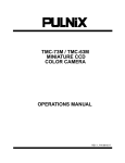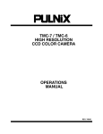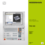
1
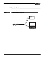
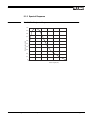
TM-7EG (RS-170)
TM-6EG (CCIR)
High Resolution Miniature Cylindrical Camera
Operation Manual
January 7, 2000
69-0045 Rev. A
Notice
The material contained in this manual consists of information that is proprietary to PULNiX America, Inc., and may only
be used by the purchasers of the product. PULNiX America, Inc. makes no warranty for the use of its product and assumes
no responsibility for any errors which may appear or for damages resulting from the use of the information contained
herein. PULNiX America, Inc. reserves the right to make changes without notice.
Warranty
All of our solid state cameras have a full three-year warranty. If any such product proves defective during this warranty
period, PULNiX America, Inc. will repair the defective product without charge for parts and labor or will provide a
replacement in exchange for the defective product. This warranty shall not apply to any damage, defect or failure caused
by improper use or inadequate maintenance and use.
Certifications
CE Compliance
The TM-7EG/TM-6EG has been certified to conform to the requirements of Council Directive 89/336/EC for
electromagnetic compatibility and to comply with the following European Standards:
Immunity:
EN500082-2/1995
Emissions:
EN55022:1995 Class A / CISPR 22:1993
All PULNiX products bearing the CE mark have been declared to be in conformance with the applicable EEC Council
Directives. However, certain factory installed options or customer requested modifications may compromise
electromagnetic compatibility and prohibit use of the CE mark. Please note that the use of interconnect cables that are not
properly grounded and shielded may affect CE compliance.
Contact the PULNiX Applications Engineering Department for further information regarding CE compliance.
FCC
This equipment has been tested and found to comply with the limits for a Class A digital device, pursuant to Part 15 of the
FCC Rules. These limits are designed to provide reasonable protection against harmful interference when the equipment
is operated in a commercial environment. This equipment generates, uses and can radiate radio frequency energy and, if
not installed and used in accordance with the instruction manual, may cause harmful interference to radio
communications. Operation of this equipment in a residential area is likely to cause harmful interference in which case the
user will be required to correct the interference at his own expense.
WARNING
Changes or modifications to this unit not expressly approved by the party responsible
for FCC compliance could void the user’s authority to operate the equipment.
TM-7EG/TM-6EG Operation Manual
Printing: January 2000
PULNiX America, Inc.
1330 Orleans Drive
Sunnyvale, CA 94089
Tel: (408) 747-0300
Tel: (800) 445-5444
Fax: (408) 747-0880
E-mail: [email protected]
www.pulnix.com
TABLE OF CONTENTS
1 INTRODUCTION.............................................................................................................. 1
1.1
1.2
1.3
Product Description and Applications .................................................................................................1
Features ..............................................................................................................................................1
System Configuration..........................................................................................................................3
2 INSTALLATION ............................................................................................................... 4
2.1
Getting Started....................................................................................................................................4
2.1.1 Unpacking Instructions ..............................................................................................................4
2.1.2 Components List .......................................................................................................................4
2.1.3 Accessories and Options ..........................................................................................................4
2.1.4 Power Supply and Power Cable Setup......................................................................................5
2.1.5 Attaching the Camera Lens.......................................................................................................6
2.1.6 Auto-Iris Lens Setup..................................................................................................................6
2.1.7 Monitor Display Mode................................................................................................................6
3 MODES OF OPERATION................................................................................................ 6
3.0.1
3.0.2
Timing .......................................................................................................................................7
External Input Signals ...............................................................................................................8
4 TROUBLESHOOTING..................................................................................................... 9
4.1
Problems and Solutions ......................................................................................................................9
4.1.1 Symptom: No Video...................................................................................................................9
4.1.2 Symptom: Dark Video................................................................................................................9
4.1.3 Symptom: Non-synchronized Video ..........................................................................................9
4.2 Information and Support Resources .................................................................................................10
5 APPENDIX..................................................................................................................... 11
5.1
Specifications....................................................................................................................................11
5.1.1 Product Specifications.............................................................................................................11
5.1.2 Physical Dimensions ...............................................................................................................12
5.1.3 Glass Specifications ................................................................................................................13
5.1.4 C-Mount Specifications ...........................................................................................................14
5.1.5 Spectral Response ..................................................................................................................15
i
LIST OF FIGURES
FIGURE 1. TM-7EG/TM-6EG System Configuration ............................................ 3
FIGURE 2. TM-7EG/TM-6EG Assembly Drawing Showing Flying Leads............. 5
FIGURE 3. Timing Chart ....................................................................................... 7
FIGURE 4. External Input Signals......................................................................... 8
FIGURE 5. Physical Dimensions......................................................................... 12
FIGURE 6. Camera Front End - Glass Specifications......................................... 13
FIGURE 7. Combination With “CS-Mount” Camera ............................................ 14
FIGURE 8. TM-7EG/TM-6EG Spectral Response .............................................. 15
ii
January 7, 2000
TM-7EG / TM-6EG
High Resolution
Miniature Cylindrical
Camera
Operations Manual
1
INTRODUCTION
1.1 Product Description and Applications
The TM-7EG/TM-6EG series are state-of-the-art CCD cameras which use a 1/2” high resolution
imager. These units offer outstanding compactness, high performance, long life, high stability and
variable shutter control (factory option).
They are designed to be simple yet high quality cameras for versatile applications such as machine
vision, image processing, robotics, medical, surveillance, helmet cameras, pipe inspection, underwater,
microscopy and military.
1.2 Features
•
Variable Electronic Shutter and Random CCD Integration
The TM-7EG/TM-6EG series cameras have a substrate drain-type shutter mechanism which
provides a superb picture at various speeds without smearing. The cameras have the capability to
externally vary shutter rate manually via a cable flying lead from 1/60 to 1/10,000 sec. in discrete
steps (factory option).
•
Miniaturized and Lightweight
All PULNiX cameras are built with the same design principles: solid state technology;
miniaturization of lenses, housing, and cables; specialization (such as remote imager and image
intensified camera versions). The use of a CCD image sensor in the video camera module and the
availability of special Tamron lenses make it possible to produce a very compact, lightweight, and
robust series of cameras. The TM-7EG and TM-6EG are both based on these principles, which
makes them comparable in size to a remote head.
Page 1
INTRODUCTION
•
High Sensitivity
The TM-7EG/TM-6EG series is one of the most low-light sensitive 1/2” CCD cameras available
today. This is especially important when using the faster shutter speeds. The CCD detects images
into the near infrared. It requires only 1.0 lux of minimum illumination and 0.5 lux minimum
illumination at maximum gain. In general, such a low light camera allows use of a higher lens
F-value and provides greater depth of field and sharper images.
•
Precise Image Geometry
On the CCD image sensor, the photosensor elements form exact rows both horizontally and
vertically so that a very precise image geometry may be obtained.
•
Low Lag/High Resistance To Image Burning
Compared to the lag of conventional cameras which use a pickup tube, the lag of a CCD camera is
considerably reduced, so that a clear picture may be obtained when shooting a rapid, moving
object, or when shooting in a low-illumination environment. Since the CCD is highly resistant to
image burning, the camera may be exposed to bright objects for a long period of time. It must be
noted, however, that a “smear” phenomenon may occur when shooting a very bright object. An
infrared cutoff filter is recommended to obtain a clear picture.
•
High Resistance To Magnetic Field and Vibration/Mechanical Shock
Due to its robust design, the CCD imager can withstand strong vibration and shock, and little or no
noise will appear in the picture. Since the TM-7EG/TM-6EG series cameras are not influenced by a
magnetic field, they will produce stable images even when placed next to objects such as electronic
furnaces, welding machines, or NMR scanners.
•
Quick Start-Up and Low Power Consumption
No more than 2 seconds are needed for the TM-7EG/TM-6EG series cameras to warm up, and
shooting may begin within a second after turning on the camera. The power consumption is only
3.0W. This makes the cameras excellent for use with battery operated systems.
•
Genlock Circuit
A genlock circuit is built into the TM-7EG/TM-6EG series cameras to accept external sync. These
low-cost cameras are designed to be useful in a wide variety of simple but demanding applications
which require compactness, high resolution, and high quality. External sync is built into the TM7EG/TM-6EG series for applications where external sync is required.
•
Three-Year Warranty
The CCD solid state image sensor allows the camera to maintain a superior performance level
indefinitely while requiring virtually no maintenance. PULNiX backs all of the TM Series cameras
with a three-year warranty.
Warning: Opening the camera in any way will void this warranty.
Page 2
TM-7EG / TM-6EG High Resolution Miniature Cylindrical Camera
INTRODUCTION
1.3 System Configuration
Figure 1 (below) presents a typical system configuration.
FIGURE 1.
TM-7EG/TM-6EG System Configuration
Syn
c
Pow
er
Power 12V
Ext. Sync
Output
Vid
eo
Display Monitor or PC
with frame grabber
TM-7EG / TM-6EG High Resolution Miniature Cylindrical Camera
Page 3
INSTALLATION
2
INSTALLATION
The following instructions are provided to help you set up your video camera system quickly and easily.
It is suggested that you read through these instructions prior to unpacking and setting up your camera
system.
2.1 Getting Started
2.1.1 Unpacking Instructions
It is recommended that the original packing cartons for the cameras and lenses be saved in case there is
a need to return or exchange an item.
It is also recommended that any equipment being sent to another location for field installation be bench
tested to assure that everything is fully operational as a system.
2.1.2 Components List
Please begin by checking your order against the Components List (below) to assure that you have
received everything as ordered, and that nothing has been overlooked in the packing materials. If any
item is missing, please contact your PULNiX representative immediately.
•
TM-7EG/TM-6EG camera
•
TM-7EG/TM-6EG data sheet
•
TM-7EG/TM-6EG manual
2.1.3 Accessories and Options
Following is a list of additional accessories and options that may be recommended or required for your
particular application. Please check with your PULNiX representative prior to the installation of your
video system to determine what you might need.
Page 4
•
M14 x 0.5 Tamron lens
•
C/CS-Mount
•
C/CS-Mount with Tripod Mount
•
PD-12 or K25-12V Power Supply or PD-12U Power Supply with American or European cords
•
Option OP60 (Frame Mode)
•
Option OP29-6 (Variable Shutter Control)
TM-7EG / TM-6EG High Resolution Miniature Cylindrical Camera
INSTALLATION
2.1.4 Power Supply and Power Cable Setup
2.1.4 (a)
Power Supplies
PULNiX recommends the following power supplies:
K25-12
110V AC/12V DC
2.1A power supply
K50-12
110V AC/12V DC
4.2A power supply
PD-12
110V AC/12V DC
1.2A power supply
PD-12U
90-200V AC/12V DC
1.2A power supply
The PD-12 power supply can be connected to the PULNiX power cable via a terminal strip or directly.
When wiring the PD-12 power supply directly, please note the following:
FIGURE 2.
•
The lead ends must be twisted together and tin-soldered for strength and electrical continuity.
•
Shrink tubing or a similar insulator should be used to prevent exposed leads from touching and
shorting.
•
The +12V lead is marked with a red stripe or white lettering; be sure not to reverse the leads.
•
All connections must be properly insulated to prevent shorting.
TM-7EG/TM-6EG Assembly Drawing Showing Flying Leads
≈
Brown EXT HD
White Video
Black GND
Yellow +12V
Gray GND
≈
≈ ≈
Blue EXT VD
2,000mm ± 20mm
2.1.4 (b)
“K” Series Power Supplies
Attach the 110V line cord to the two terminals marked “AC”. Do not plug the cord into a 110V AC
socket until later in the procedure. Next, attach the gray and yellow leads of the power cable to the
ground and 12V DC terminals respectively. Be sure to replace the plastic terminal guard on the power
supply at this time.
Note: The “K” series power supplies are designed primarily for OEM users who will be mounting the
power supply inside a protective enclosure. For use in exposed situations, the PD-12 and PD-12U are
recommended.
TM-7EG / TM-6EG High Resolution Miniature Cylindrical Camera
Page 5
MODES OF OPERATION
2.1.5 Attaching the Camera Lens
The TM-7EG/TM-6EG has various types of lens mounts available as an option. The cylindrical
enclosure has M14 x 0.5 threads to adapt a Tamron aspherical lens, or a C/CS-mount lens can also be
used. Do not force the lens if it does not seat properly. Please note that some lenses with extremely long
flangebacks may exceed the mounting depth of the camera.
2.1.6 Auto-Iris Lens Setup
Auto-iris lenses with full video input can be used with the PULNiX TM-7EG/TM-6EG, although this
camera model does not come equipped with auto-iris output.
Note: Make sure that the power is removed from the camera before connecting or disconnecting the
auto-iris lens. There is a small chance that the auto-iris lens could be damaged by plugging or
unplugging it while the camera is powered up.
Power down the camera before installing the auto-iris lens. To install the auto-iris lens in a PULNiX
camera for which the auto-iris input is not supplied, wire the signal (video) on the lens into the terminal
1 V peak to peak video output on the camera.
Point the camera at a light area and then quickly towards a darker area. If everything is working
properly, the iris should adjust for the light change.
2.1.7 Monitor Display Mode
For monitoring real time video, connect the video output to a video monitor or other device.
3
MODES OF OPERATION
Standard factory setting for this mode selection is Field Mode. Frame Mode is available as a factory
option (OP 6).
3.0.0 (a)
Field Mode
Field mode scans two horizontal rows together and changes the pair at each interlace scanning. This
mode is advantageous when using shutter. The sensitivity of the CCD is doubled for one field of
integration (with shutter, integration cannot exceed one field) resulting in the same sensitivity as the
Frame Mode for half of the time period. The alternating two-row scanning results in a Moire pattern that
is hardly noticeable. Although Field Mode vertical resolution is not as good as in Frame Mode, it is
sufficient to see the full vertical resolution of the TV format. Field Mode cannot be used for applications
needing strobe lighting since it does not achieve full frame resolution.
3.0.0 (b)
Frame Mode
Frame Mode scans each horizontal row as interlace scanning. During Frame Mode, integration of each
pixel is one frame period (i.e. 33 msec for EIA, TM-7EG and 40 msec for CCIR, TM-6EG). Vertical
pixel resolution is good and exact pixel location is obtained. Frame Mode tends to show vertical Moire
Page 6
TM-7EG / TM-6EG High Resolution Miniature Cylindrical Camera
MODES OF OPERATION
pattern. For applications needing strobe lighting, Frame Mode should be used in order to achieve full
frame resolution.
Note: The factory setting for the TM-7EG/TM-6EG cameras is Field Mode. If Frame Mode is
required, contact PULNiX for the setting. The mode selection is a solder jumper on the process
board. Opening the camera voids the warranty.
3.0.1 Timing
FIGURE 3.
Timing Chart
HD
811
768
B45
40
757
758
759
760
761
762
763
764
765
766
767
768
3
B1
B2
B3
B4
B5
1
2
3
4
5
6
7
8
9
10
D1
34
D22
77
B45
B1
767
768
40
B1
91
2
CCD photo sensors
allocation
H register
stop period
Optical
black period
Image sensing period
Dummy
H register
Optical
black period
CCD output
signal
Effective picture
period
154
H BLK 10.7µSec
Composite video
output
21
56
H SYNC
77
756
52.81µSec
1ck=69.84nSec
910
63.56µSec (1 horizontal line)
TM-7EG / TM-6EG High Resolution Miniature Cylindrical Camera
Page 7
MODES OF OPERATION
3.0.2 External Input Signals
FIGURE 4.
External Input Signals
1/HD frequency
+5Volts HD
TTL Level
0 Volts
1 - 2µsec.
1/VD frequency
+5Volts VD
TTL Level
0 Volts
1 to 9H
External Sync.
Page 8
TM-7EG:
HD = 15.734 KHz ± 5%
VD = 59.94 Hz ± 5%
TM-6EG:
HD = 15.625 KHz ± 5%
VD = 50 Hz ± 5%
TM-7EG / TM-6EG High Resolution Miniature Cylindrical Camera
TROUBLESHOOTING
4
TROUBLESHOOTING
4.1 Problems and Solutions
Following are troubleshooting tips for common problems. Generally, problems can easily be solved by
following these instructions. If the following remedies fail to offer a solution to your problems, please
contact a PULNiX representative.
4.1.1 Symptom: No Video
Remedies: Check that the following are properly connected and operational.
•
Power supplies
•
Power cables
•
Main power source
•
Lens
4.1.2 Symptom: Dark Video
Remedies: Check that the following are properly connected and operational.
•
Shutter selection
•
Iris opening on the lens
4.1.3 Symptom: Non-synchronized Video
Remedies: Check that the following are properly connected and operational.
•
Proper mode output
•
Frame grabber software camera selection
TM-7EG / TM-6EG High Resolution Miniature Cylindrical Camera
Page 9
TROUBLESHOOTING
4.2 Information and Support Resources
For further information and support:
Phone:
(408) 747-0300
(800) 445-5444
(800) 3-PULNIX (24-hour message access)
Fax:
(408) 747-0660
E-mail:
[email protected]
Mail:
PULNiX America, Inc.
Sales Department
1330 Orleans Drive
Sunnyvale, CA 94089
ATTN: Video Applications
Web Site:
Page 10
www.pulnix.com
TM-7EG / TM-6EG High Resolution Miniature Cylindrical Camera
APPENDIX
5
APPENDIX
5.1 Specifications
5.1.1 Product Specifications
TABLE 1.
TM-7EG/TM-6EG Product Specifications Table
Model
TM-7EG Series
Imager
Pixels
TM-6EG Series
1/2 inch interline transfer CCD
768 (H) x 494 (V)
752 (H) x 582 (V)
Cell size
8.4 µ x 9.8 µm
8.6 µ x 8.3 µm
Scanning
525 lines EIA
625 lines CCIR
fH=15.734 KHz ± 5%
fV=59.94 Hz ± 5%
fH=15.625 KHz ± 5%
fV=50 Hz ± 5%
570 (H) x 350 (V)
560 (H) x 420 (V)
Sync
TV resolution
S/N Ratio
50 dB min., 56dB typical
Min. illumination
0.5 lux (F=1.4) without IR cut filter
Video output
1.0V p-p composite video, 75Ω
AGC
On / Off (Off is factory default)
Gamma
0.45 or 1 (1 is factory default)
Lens mount
M14 x 0.5 Tamron, C/CS-mount
Power requirement
DC 12V, 2.5W
-10 o C to 50 o C
Operating temp.
Random Vibration
7 Grms @ 10-2000 Hz;
Shock
70 G
Size (Dia. x L)
17mm (Dia.) x 101.9 mm (L)
0.67” (Dia.) x 4.0” (L)
Weight
34.0g (1.2 oz.)
Power Cable
Flying lead (Power, Video, Sync)
Power Supply
K25-12V or PD-12U (For 110V mains)
Auto iris connector
Accessories
None
C/CS-mount lens adapter (PN 32-3770) or
C/CS-mount lens adapter with tripod mount (PN 32-3672)
Options
TM-7EG / TM-6EG High Resolution Miniature Cylindrical Camera
OP60 (Frame mode)
OP29-6 (Variable Shutter Control)
Page 11
APPENDIX
5.1.2 Physical Dimensions
FIGURE 5.
Physical Dimensions
TAMRON LENS #12F005
ICX038DLB
ø20.0 [0.79]
11.2 [0.44]
100.5 [3.96]
118.8 [4.68]
ø17.0 [0.67]
TM-7EG WITH TAMRON LENS MOUNT
ICX038DLB
Ø28.3 [1.11]
106.8 [4.21]
TM-7EG WITH CS-MOUNT
Ø17.0 [0.67]
(Part NO. 32-3770)
Ø33.0 [1.30]
106.8 [4.21]
Ø17.0 [0.67]
1/4-20"
TM-7EG WITH CS-MOUNT AND TRIPOD MOUNT
(Part No. 32-3672)
Page 12
TM-7EG / TM-6EG High Resolution Miniature Cylindrical Camera
APPENDIX
5.1.3 Glass Specifications
FIGURE 6.
Camera Front End - Glass Specifications
TAMRON LENS #12F005
REF
ICX038DLB
IMAGER BOARD
M2 SET SCREW
FRONT END
TM-7EG / TM-6EG High Resolution Miniature Cylindrical Camera
HOUSING
Page 13
APPENDIX
5.1.4 C-Mount Specifications
The Flange Back Length of the CS-Mount is 12.5mm versus 17.526mm of the C-Mount. The C/CS
mount adapter for the TM-7EG can accommodate either style lens. In order to determine the position of
the lens and the adapter, the following procedure should be implemented.
1.
2.
3.
4.
5.
FIGURE 7.
Attach the lens to the adapter.
Loosen the set screws on the adapter and slide it over the camera body.
Set the lens focus to infinity and point the camera at a distant object.
Slide the adapter up/down until the image is in focus.
Tighten the three set screws on the adapter.
Combination With “CS-Mount” Camera
CS-Mount Lens
Focal Point
5mm Extension Ring
C-Mount Lens
5
12.5
17.526
Flange Surface of
C-Mount
Page 14
TM-7EG / TM-6EG High Resolution Miniature Cylindrical Camera
APPENDIX
5.1.5 Spectral Response
FIGURE 8.
TM-7EG/TM-6EG Spectral Response
1.0
0.9
0.8
0.7
Relative Sensitivity
0.6
0.5
0.4
0.3
0.2
0.1
0
400
500
600
700
TM-7EG / TM-6EG High Resolution Miniature Cylindrical Camera
800
900
Wave Length (nm)
1000
Page 15
APPENDIX
Page 16
TM-7EG / TM-6EG High Resolution Miniature Cylindrical Camera
Industrial Products Division
PULNiX America, Inc.
1330 Orleans Drive
Sunnyvale, CA 94089
Tel: 408-747-0300
Tel: 800-445-5444
Fax: 408-747-0660
Email: [email protected]
www.pulnix.com
69-0045 Rev. A
Printed: 1/00