1
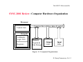
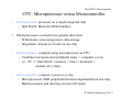
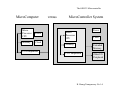
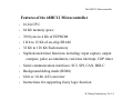
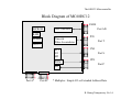
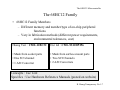
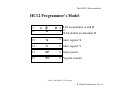
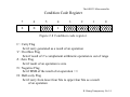
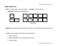
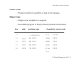
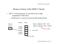
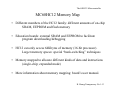
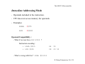
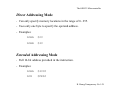
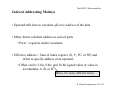
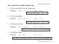
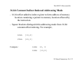
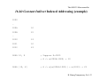
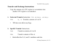
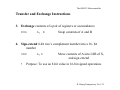
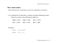
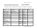
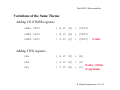
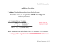
The 68HC12 Microcontroller
Chapter 1
Introduction to 68HC12
Assembly Notation :
Intel
binary
10010011b
decimal
1478
hexadecimal 5678h
Motorola
%10010011
1478
$5678
H. Huang Transparency No.1-1
The 68HC12 Microcontroller
SYSC-2001 Review : Computer Hardware Organization
Processor
Control Unit
Common Bus (address, data, & control)
Datapath
Arithmetic
Logic Unit
Registers
Memory
Program &
Data Storage
Output
Units
Input
Units
Figure 1.1 Computer Organization
H. Huang Transparency No.1-2
The 68HC12 Microcontroller
CPU: Microprocessor versus Microcontroller
•
Microprocessor: processor on a single integrated chip
– Intel 80x86, Motorola 680x0 families...
•
Microprocessors evolved in two general directions:
– Performance: processing power, data storage
– Integration: amount of circuits on one chip
•
Microcomputer: computer using microprocessor as CPU
– Combines microprocessor/peripheral chips -> computer system
– i.e.: PC => Intel 80x86 + memory + timer + keyboard +
modem (etc.) chips
•
Microcontroller: computer system on a chip
– Microprocessor AND peripheral functions implemented on one chip
– Built-in memory and interface circuits (I/O units)
H. Huang Transparency No.1-3
The 68HC12 Microcontroller
MicroComputer
versus
MicroController System
Power
Micro
Processor
CPU
Power
Memory
Clock
I/O Components
Micro
Processor
CPU
Clock
Memory
Extended
Memory
I/O Components
Other I/O
Peripheral
H. Huang Transparency No.1-4
The 68HC12 Microcontroller
Features of the 68HC12 Microcontroller
- 16-bit CPU
- 64 Kb memory space
- 768 bytes to 4 Kb of EEPROM
- 1 Kb to 12 Kb of on-chip SRAM
- 32 Kb to 128 Kb flash memory
- Sophisticated timer functions including: input capture, output
compare, pulse accumulators, real-time interrupt, COP timer
- Serial communication interfaces: SCI, SPI, CAN, BDLC
- Background debug mode (BDM)
- 8-bit or 10-bit A/D converter
- Instructions for supporting fuzzy logic function
H. Huang Transparency No.1-5
The 68HC12 Microcontroller
Block Diagram of MC68HC12
PAD0
EEPROM
Port AD
A/D Converter
RAM
FLASH
Timer &
Pulse Accumulator
PT0
Port T
CPU12
SCI
I/O
SPI
PWM
PS0
Port S
PP0
Port P
I/O
Port A*
Port B*
* Multiplex : Simple I/O or Extended Address/Data
H. Huang Transparency No.1-6
The 68HC12 Microcontroller
The 68HC12 Family
• 68HC12 Family Members
– Different memory and number/type of on-chip peripheral
functions
– Vary in fabrication methods (different power requirements,
environmental tolerances, cost)
Huang Text : CME-12BC32
Our lab : CML-9S12DP256
• Made from socket parts
• One SCI channel
• 1 A/D Converter
• Made from surface-mount parts
• Two SCI Channels
• 2 A/D Converters
Concepts : Use Text
Specifics : Use Hardware Reference Manuals (posted on website)
H. Huang Transparency No.1-7
The 68HC12 Microcontroller
HC12 Programmer’s Model
7
15
A
07
D
B 0 8-bit accumulator A and B
0 or
16-bit double accumulator D
15
X
0 Index register X
15
Y
0 Index register Y
15
SP
0 Stack pointer
15
PC
0 Program counter
Figure 1.3 MC68HC12 CPU registers.
H. Huang Transparency No.1-8
The 68HC12 Microcontroller
Condition Code Register
7
6
5
4
3
2
1
0
S
X
H
I
N
Z
V
C
Figure 2.8 Condition code register
C : Carry Flag
Set if carry generated as a result of an operation
V : Overflow Flag
Sets if result of 2’s complement arithmetic operation is out of range
Z : Zero Flag
Set if result of an operation is zero
N : Negative Flag
Set if MSB of the result of an operation = 1
H : Half-carry Flag
Set if carry from lower four bits to upper four bits as a result
of an operation
H. Huang Transparency No.1-9
The 68HC12 Microcontroller
Instruction Set
- 68HC12 instructions: one/two bytes -> opcode; zero-five bytes
-> operand (addressing information).
Opcode
$18
Opcode
Operands
- Opcode: operation to be performed. First byte of two-byte opcode always $18.
- Instruction (opcodes) classified into three groups
1. Data Transfer
2. Data Manipulation (Arithmetic and Logic)
3. Control Flow
H. Huang Transparency No.1-10
The 68HC12 Microcontroller
Source Code
- Program written in assembly or high-level language
Object Code
- Output of an assembler or compiler
- Executable program in binary format (machine instructions)
line
addr.
1:
machine code
(Assembly) source code
= 00001000
org
$1000
2:
1000
B6 0800
ldaa
$800
3:
1003
BB 0801
adda
$801
4:
1006
BB 0802
adda
$802
6:
1009
7A 0900
staa
$900
end
H. Huang Transparency No.1-11
The 68HC12 Microcontroller
Memory Format of the 68HC12 family
• HC12: 16-bit processor. It can read 16-bit words
organized as 8-bit bytes.
– On Motorola’s, words accessed with Big Endian format
Address
Memory
Address
1202
$1200
$1201
$1202
$1203
$1204
Data
5E
73
A2
95
0A
Byte at Address 1202 = $A2
Word at Address 1202 = $A295
Big Endian
%1010 0010
Data is 8 bits
H. Huang Transparency No.1-12
The 68HC12 Microcontroller
MC68HC12 Memory Map
• Different members of the HC12 family: different amounts of on-chip
SRAM, EEPROM and flash memory
• Education boards: external SRAM and EEPROM to facilitate
program downloading/debugging
• HC12 can only access 64Kbytes of memory (16-bit processor).
Larger memory spaces: special “bank-switching” techniques
• Memory mapped to allocate different kinds of data and instructions
(single-chip; expanded mode)
• More information about memory mapping: board’s user manual.
H. Huang Transparency No.1-13
The 68HC12 Microcontroller
MC68HC12 Memory Map for DP256
Simulator
Lab
FFFF
FF00 Vector Address
FFFF
EEPROM and Flash
External EEPROM
8000
7FFF 16kbytes External RAM
Code
4000
3FFF
8000
7FFF 16kbytes External RAM
4000
3FFF
12Kbytes Internal RAM
1FFF
1000
0FFF
Data
4kbytes Internal EEPROM
1000
BFF
8 kbytes Internal EEPROM
1 Kbytes Internal RAM
800
400
3FF
3FF
200 Peripheral Area
1FF
0000 HC12 Internal Registers
200 Peripheral Area
1FF
0000 HC12 Internal Registers
H. Huang Transparency No.1-16
The 68HC12 Microcontroller
HC12 Simulator
• Microcontroller simulator: tool (program) that replicates
the operation of a microcontroller
– Learn about/ develop code without having the hardware
• HC12 simulator mimics operation of HC12 microcontroller
– Displays and changes “registers”
– Displays and changes “memory”
– “Executes” code, changing contents of simulated memory/ registers
according to the semantics of instructions executed
H. Huang Transparency No.1-17
The 68HC12 Microcontroller
HC12 Simulator
We will use a freeware simulator available at
http://www.electronikladen.de/hc12
This simulator is a Java program, so you will need to have a JDK on your
machine
www.sun.org
Instructions for running the simulator are provided in a note on the course
webpage.
H. Huang Transparency No.1-18
The 68HC12 Microcontroller
Simulator Demo
H. Huang Transparency No.1-19
The 68HC12 Microcontroller
I/O Ports and I/O Addresses
Enable exchange of data between chip and external I/O devices
- A port for a particular device identified by I/O Address
Address
Decoder
CE
Interface
chip 1
CE
Interface
chip 1
Micro
processor
Data Bus
Figure 7.1 Interface chip, I/O devices, and microprocessor
H. Huang Transparency No.1-20
The 68HC12 Microcontroller
I/O Addressing Schemes: Isolated I/O
- Based on a separate address space for I/O devices.
- Programming: use dedicated instructions for I/O operations.
Control (RD/WR)
Memory Map
Processor
FFFF
Data
I/O Map
0xFF
Address
Memory
0000
I/O Device
0000
I/O Control (IOR/IOW)
H. Huang Transparency No.1-21
The 68HC12 Microcontroller
I/O Addressing Scheme : Memory Mapped I/O
• Both I/O and memory shared same memory space.
• Programmer’s: same instructions for both memory and I/O
Memory Map
Control (RD/WR)
Processor
FFFF
Data
Address
Memory
I/O Device
I/O Map
0000
H. Huang Transparency No.1-22
The 68HC12 Microcontroller
Programming MicroControllers
Using a High-level Language
•
Syntax: closer to human languages
•
Translator (Compiler): convert program in high-level language into machine language
•
Allow the users to work on the program logic at higher level.
Machine Language (executable code)
•
Sequence of binary digits that can be executed by the processor
Assembly Language (mnemonic code)
•
•
Assembly instruction: representation of a machine instruction
(1 assembly instruction = 1 machine instruction)
Hard to understand, program, and debug for humans
Real-Time Embedded Systems programming
•
•
High level languages not adequate: performance issues
Memory space (Java exe >> C exe >> Assembly exe = machine exe)
H. Huang Transparency No.1-23
The 68HC12 Microcontroller
68HC12 Instruction Examples: Load and Store
- LOAD: copies contents of operand into CPU register.
- STORE: save contents of CPU register into memory location.
- Execution affects certain flags
- N and Z flags of the CCR automatically updated; V flag cleared.
Learning HC12 Instructions : (1) Built-in Operands
Mnemonic
STAA
STAB
STD
STS
STX
STY
Function
Store A
Store B
Store D
Store SP
Store X
Store Y
Operation
(A) ⇒M
(B) ⇒M
(A) ⇒M, (B) ⇒ M+1
(SP) ⇒M, M+1
(X) ⇒M:M+1
(Y) ⇒M:M+1
H. Huang Transparency No.1-24
The 68HC12 Microcontroller
Learning New HC12 Instructions (1) : Built-in Operands
Mnemonic
LDAA
LDAB
LDD
LDS
LDX
LDY
LEAS
LEAX
LEAY
Function
Operation
Load A
(M) ⇒ A
Load B
(M) ⇒B
Load D
(M:M+1) ⇒(A:B)
Load SP
(M:M+1) ⇒SP
Load index register X
(M:M+1) ⇒ X
Load index register Y
(M:M+1) ⇒ X
Load effective address into SP Effective address ⇒SP
Load effective address into X Effective address ⇒X
Load effective address into Y Effective address ⇒Y
H. Huang Transparency No.1-25
The 68HC12 Microcontroller
Flags = SXHINZVC
Learning New HC12 Instructions (2) : Addressing Modes
Source
Operation
Mode
Coding
Flags
LDAA #opr8i
(M)=>A
IMM
86 ii
----xx0-
LDAA opr8a
Load Accumulator A DIR
96 ii
LDAA opr16a
EXT
B6 hh ll
LDAA oprx0_xysp
IDX
A6 xb
LDAA oprx9, xysp
IDX1
A6 xb ff
LDAA oprx16,xysp
IDX2
A6 xb ee ff
LDAA [D, xysp]
[D,IDX] A6 xb
LDAA
[oprx16,xysp]
[IDX2]
A6 xb ee ff
H. Huang Transparency No.1-26
The 68HC12 Microcontroller
Addressing Modes
Inherent Addressing Mode
- Instructions do not use extra bytes for operands: instructions
either do not need operands or all operands are
CPU registers.
- Operands are implied by the opcode.
- Examples:
NOP
INX
DECA
H. Huang Transparency No.1-27
The 68HC12 Microcontroller
Immediate Addressing Mode
- Operands included in the instruction.
- CPU does not access memory for operands.
- Examples:
LDAA
#$55
LDX
#$800
Operand Compatibility :
- What if we now have LDX #$55 ?
Instruction encoding :
• LDAA #$55
• LDX #$55
86
55
CE
00 55
- What’s wrong with this ? LDAA #$1234
H. Huang Transparency No.1-28
The 68HC12 Microcontroller
Direct Addressing Mode
- Can only specify memory locations in the range of 0– 255.
- Uses only one byte to specify the operand address.
- Examples:
LDAA
$20
LDAB
$40
Extended Addressing Mode
- Full 16-bit address provided in the instruction.
- Examples:
LDAA
$4000
LDX
$FE60
H. Huang Transparency No.1-29
The 68HC12 Microcontroller
Indexed Addressing Mode(s)
• Operand tells how to calculate effective address of the data
• Many forms calculate address as sum of parts
• Parts = registers and/or constants.
• Effective address = Sum of index register (X, Y, PC, or SP) and
offset to specify address of an operand.
• Offset can be 5-bit, 9-bit, and 16-bit signed value or value in
accumulator A, B, or D
Hence, the many different forms …
H. Huang Transparency No.1-30
The 68HC12 Microcontroller
The Various Forms of Indexed Addressing
1.
5-bit Constant Offset (Indexed Addressing)
Examples : ldaa
2.
0,X
stab -8,X
The range of the offset : -16 to +15.
9-bit Constant Offset
Examples : ldaa
$FF,X
ldab
-20,Y
The range of the offset : -256 to +255
3.
16-bit Constant Offset
Examples:
ldaa
2000,X
staa
4000,Y
Allows access any location in the 64-KB range
4.
Accumulator Offset
Examples:
ldaa
B,X
stab
B,Y
The offset is contained in either A, B or the 16-bit accumulator D.
H. Huang Transparency No.1-31
The 68HC12 Microcontroller
16-bit Constant Indirect Indexed Addressing Mode
- 16-bit offset added to index register to form address of memory
location containing a pointer to memory location affected by
the instruction.
- Square brackets distinguish this addressing mode from 16-bit
constant offset indexing. For example,
LDAA
[10,X]
STAA
[20,Y]
Compare :
LDAA
10, X
LDAA
[10,X]
H. Huang Transparency No.1-32
The 68HC12 Microcontroller
16-bit Constant Indirect Indexed Addressing (example)
1000
…
100A
10
100B
22
…
1020
2f
1021
10
1022
ff
LDAA 10, X
; Suppose X=1000
; A <- m(000A+1000) = 10
LDAA [10, X]
; A <- m[m(000A+1000)] = m(1022) = ff
H. Huang Transparency No.1-33
The 68HC12 Microcontroller
Transfer and Exchange Instructions
-
Copy the contents of a CPU register or accumulator into
another CPU register or accumulator.
1. Universal Transfer Instruction: TFR abcdxys, abcdxys
TFR
•
A, B Transfers contents of A to B
TFR does not affect any flags.
2. Specific Transfer Instructions
TAB
Transfers contents of A to B
TBA
Transfer contents of B to A
•
Both affect the N, Z, and V condition code bits.
H. Huang Transparency No.1-34
The 68HC12 Microcontroller
Transfer and Exchange Instructions
3. Exchange contents of a pair of registers or accumulators.
EXG
A, B
Swap contents of A and B
4. Sign-extend 8-bit two’s complement number into a 16- bit
number
SEX
•
A,X
Move contents of A into LSB of X,
and sign extend
Purpose: To use an 8-bit value in 16-bit signed operations.
H. Huang Transparency No.1-35
The 68HC12 Microcontroller
Move Instructions
- Move data bytes or words from a source to a destination in memory.
- Six combinations of immediate, extended, and index addressing modes
allowed to specify source/destination addresses:
IMM ⇒ EXT,
IMM ⇒ IDX,
EXT ⇒ EXT,
EXT ⇒ IDX,
IDX ⇒ EXT,
IDX ⇒ IDX
- Examples:
MOVB
$100,$800
MOVW
0,X, 0,Y
H. Huang Transparency No.1-36
The 68HC12 Microcontroller
Flags = SXHINZVC
Add and Subtract Instructions
• Destinations of these instructions are always a CPU register or accumulator.
Source
Operation
Mode
Coding
Flags
ADDA #opr8i
(A)+(M)=>A
IMM
8B ii
--x–xxxx
ADDA opr8a
Add w/o Carry to A DIR
9B ii
ADDA opr16a
EXT
BB hh ll
ADDA oprx0_xysp
IDX
AB xb
ADDA oprx9, xysp
IDX1
AB xb ff
ADDA
oprx16,xysp
IDX2
AB xb ee
ff
ADDA [D, xysp]
[D,IDX] AB xb
ADDA
[oprx16,xysp]
[IDX2]
AB xb ee
ff
H. Huang Transparency No.1-37
The 68HC12 Microcontroller
Variations of the Same Theme
Adding TO OTHER registers
adda $800
; A ⇐ [A] + [$800]
addb $800
; B ⇐ [B] + [$800]
addd $800
; D ⇐ [D] + [$800]
WORD!
Adding TWO registers
aba
; A ⇐ [A] + [B]
abx
; X ⇐ [B] + [X]
aby
Notice : Order
; Y ⇐ [B] + [Y] of operands
H. Huang Transparency No.1-38
The 68HC12 Microcontroller
Addition Overflow
Problem: Fixed width registers have limited range.
Overflow: result of an operation outside the range that
can be represented
8-bit Unsigned Integer Example:
25510 =
1111 11112
+ 110 = 0000 0001
256 ?? 010 = (1) 0000 00002
Need 9 bits to
represent result
In this (unsigned) case, with fixed 8-bits: OVERFLOW OCCURRED!
• A carry @ msb is important in the INTERPRETATION of the result.
H. Huang Transparency No.1-39
The 68HC12 Microcontroller
Addition Overflow
Is that the only interpretation of the example?
1111 11112
+
0000 00012
(1)
0000 00002
Result is correct if the values are interpreted as 2’s
complement signed integers! ( – 1 + 1 = 0 )
• In that case, no overflow, and carry at MSB
not important!
H. Huang Transparency No.1-40
The 68HC12 Microcontroller
Addition Overflow
OVERFLOW DEPENDS ON THE INTERPRETATION OF
VALUES!
Another example:
unsigned
0111 11112
+ 0000 00012
1000 00002
127
+ 1
128
UNSIGNED OVERFLOW
Did NOT occur
• The C flag is cleared.
signed
127
+ 1
– 128
SIGNED OVERFLOW did occur!
(even though there is no carry
outside of fixed width!)
• The V flag is set.
H. Huang Transparency No.1-41
The 68HC12 Microcontroller
Example: Suppose that A contains $73
Execute:
ADDA #$40
$73 + $40 = ?
Results:
Overflow ?
A := $B3 ( = %1011 0011 )
Z := 0 result ≠ 0
N := 1 result is negative (signed)
C := 0 (no carry out of msbit)
V := 1
+ve + +ve = −ve
H. Huang Transparency No.1-42