Download PDF document - Eetasia.com

Transcript
MMDS11OM/D
NOVEMBER 1993
MMDS11
MOTOROLA MODULAR
DEVELOPMENT SYSTEM
OPERATIONS MANUAL
 MOTOROLA, Inc., 1991, 1993; All Rights Reserved.
Motorola reserves the right to make changes without further notice to any products herein to improve
reliability, function, or design. Motorola does not assume any liability arising out of the application or use
of any product or circuit described herein; neither does it convey any license under its patent rights nor the
rights of others. Motorola products are not designed, intended, or authorized for use as components in
systems intended for surgical implant into the body, or other application in which the failure of the
Motorola product could create a situation where personal injury or death may occur. Should Buyer purchase
or use Motorola products for any such unintended or unauthorized application, Buyer shall indemnify and
hold Motorola and its officers, employees, subsidiaries, affiliates, and distributors harmless against all
claims, costs, damages, and expenses, and reasonable attorney fees arising out of, directly or indirectly, any
claim of personal injury or death associated with such unintended or unauthorized use, even if such claim
alleges that Motorola was negligent regarding the design or manufacture of the part.
Motorola and the Motorola logo are registered trademarks of Motorola Inc.
Motorola Inc. is an Equal Opportunity/Affirmative Action Employer.
MS-DOS is a registered trademark of Microsoft Corporation. IBM is a registered trademark of
IBM Corporation.
CONTENTS
CONTENTS
CHAPTER 1 INTRODUCTION
1.1
1.2
1.3
1.4
1.5
General ................................................................................ 1-1
System Features ..................................................................... 1- 1
System Components ............................................................... 1- 3
Host Computer Requirements................................................... 1-4
About This Manual ................................................................ 1-5
CHAPTER 2 LOADING AND INITIALIZATION
2.1 Software Distribution Format .................................................. 2-1
2.2 Installing MMDS11 Software ................................................... 2-1
2.2.1 Personality Files ............................................................. 2-1
2.2.2 The Help File ................................................................. 2-2
2.3 Using The Software................................................................ 2-2
CHAPTER 3 USER SCREENS
3.1 General Description ............................................................... 3-1
3.2 The Debug Screen .................................................................. 3-1
3.2.1 The Status Area ............................................................. 3-3
3.2.2 The CPU Window ........................................................... 3-4
3.2.3 The Source/Code F2 Window ........................................... 3-4
3.2.4 The Variables F8 Window................................................ 3-5
3.2.5 The Memory F3 Window .................................................. 3-6
3.2.6 The Debug F10 Window .................................................. 3-6
3.2.7 The Stack Window.......................................................... 3-7
3 . 2 . 8 T h e A n a l yz e r T r a c e W i n d o w . . . . . . . . . . . . . . . . . . . . . . . . . . . . . . . . . . . . . . . . . . . . 3 - 8
3.2.9 The Set Memory Window ................................................. 3-8
3.2.10 The Options Window ...................................................... 3-9
3.2.11 The Baud Window .......................................................... 3-9
3.2.12 The Emulator Clock Frequency Window........................... 3-10
3.2.13 The Time Tag Window .................................................. 3-10
3.3 Mouse Operation ................................................................. 3-11
3.4 Changing Screen Colors ........................................................ 3-12
MMDS11OM/D
i
MOTOROLA
CONTENTS
CHAPTER 4 OPERATION
4.1 Introduction .......................................................................... 4-1
4.2 Initialization ......................................................................... 4-1
4.2.1 Communications Baud Rate .............................................. 4-1
4.2.2 Standard Memory Mapping ............................................... 4-2
4.2.3 Custom Memory Mapping ................................................. 4-2
4.2.4 Initializing the Emulator .................................................. 4-2
4.2.5 Loading the Target Software ............................................. 4-3
4.2.6 Memory Initialization ...................................................... 4-4
4.2.7 CPU Registers ................................................................ 4-4
4.2.8 Log Initialization ............................................................ 4-4
4.3 Common Operations ............................................................... 4-5
4 . 3 . 1 S ys t e m C o m m a n d s . . . . . . . . . . . . . . . . . . . . . . . . . . . . . . . . . . . . . . . . . . . . . . . . . . . . . . . . . . . 4 - 5
4.3.2 Operating Commands ....................................................... 4-6
CHAPTER 5 BUS STATE ANALYSIS
5.1 Introduction .......................................................................... 5-1
5 . 2 O p e r a t i n g T h e B u s S t a t e A n a l yz e r . . . . . . . . . . . . . . . . . . . . . . . . . . . . . . . . . . . . . . . . . . . . 5 - 1
5.2.1 Defining Events (Terms) .................................................. 5-2
5.2.2 Selecting the Trigger Mode .............................................. 5-5
5.2.3 Selecting Options ............................................................ 5-7
5.2.4 Collecting Bus Data ........................................................ 5-8
5.2.5 Viewing Data................................................................... 5-8
5.2.6 Searching the Trace Buffer ............................................. 5-14
5.2.7 Using the Time-Tag Clock .............................................. 5-15
CHAPTER 6 COMMAND-LINE COMMANDS
6.1
6.2
6.3
6.4
Introduction .......................................................................... 6-1
C o m m a n d S yn t a x . . . . . . . . . . . . . . . . . . . . . . . . . . . . . . . . . . . . . . . . . . . . . . . . . . . . . . . . . . . . . . . . . . . 6 - 1
Subordinate Key Commands .................................................... 6-3
Command Explanations ........................................................... 6-3
A ....................................................................................... 6-6
ARM .................................................................................. 6-7
ASM................................................................................... 6-8
B ....................................................................................... 6-9
BAUD............................................................................... 6-10
BAUDCHK ........................................................................ 6-11
BELL ............................................................................... 6-12
MMDS11OM/D
ii
MOTOROLA
CONTENTS
CHAPTER 6 COMMAND-LINE COMMANDS (continued)
BF ...................................................................................
BPROT .............................................................................
BR ...................................................................................
C .....................................................................................
CCR .................................................................................
CHIPINFO .........................................................................
CLEARMAP ......................................................................
COLORS ...........................................................................
D .....................................................................................
DARM ..............................................................................
DASM ..............................................................................
EMUBP.............................................................................
EMURAM .........................................................................
ENDBSA ...........................................................................
EVAL ...............................................................................
EXIT ................................................................................
EXPANDED ......................................................................
G .....................................................................................
GETBSA ...........................................................................
GO ...................................................................................
GOTIL ..............................................................................
H .....................................................................................
HELP ...............................................................................
HOMEBSA ........................................................................
I ......................................................................................
INFO ................................................................................
INIT .................................................................................
INIT2 ...............................................................................
LF ....................................................................................
LOAD ...............................................................................
LOADMAP ........................................................................
LOADMEM .......................................................................
LOADTRIGGERS ...............................................................
MD ..................................................................................
MM ..................................................................................
MODE ..............................................................................
N .....................................................................................
NEXTA .............................................................................
NEXTB .............................................................................
NEXTC .............................................................................
NEXTD .............................................................................
NEXTE .............................................................................
NOBR ...............................................................................
MMDS11OM/D
iii
6-13
6-14
6-16
6-17
6-18
6-19
6-20
6-21
6-22
6-23
6-24
6-25
6-26
6-27
6-28
6-29
6-30
6-31
6-32
6-33
6-34
6-35
6-36
6-37
6-38
6-39
6-40
6-42
6-44
6-45
6-46
6-47
6-48
6-49
6-50
6-51
6-52
6-53
6-54
6-55
6-56
6-57
6-58
MOTOROLA
CONTENTS
CHAPTER 6 COMMAND-LINE COMMANDS (continued)
OPTION ............................................................................ 6-59
OSC ................................................................................. 6-61
PC ................................................................................... 6-62
QUIT ................................................................................ 6-63
REG ................................................................................. 6-64
REM................................................................................. 6-65
RESET.............................................................................. 6-66
RESETGO ......................................................................... 6-67
RESETIN .......................................................................... 6-68
RESETOUT ....................................................................... 6-69
RTMEM ............................................................................ 6-70
RTVAR ............................................................................. 6-71
S ..................................................................................... 6-73
SCREENBSA ..................................................................... 6-74
SCRIPT ............................................................................ 6-75
SETMEM .......................................................................... 6-76
SHELL.............................................................................. 6-78
SHOWMEM ....................................................................... 6-79
SHOWTRIGGER ................................................................ 6-80
SINGLECHIP ..................................................................... 6-81
SOURCE ........................................................................... 6-82
SPECIALBOOT .................................................................. 6-83
SPECIALTEST ................................................................... 6-84
STACK ............................................................................. 6-85
STEP ................................................................................ 6-86
STEPFOR .......................................................................... 6-87
STEPTIL ........................................................................... 6-88
STOP ............................................................................... 6-89
SXB ................................................................................. 6-90
SYSINFO .......................................................................... 6-91
T ..................................................................................... 6-92
TIMETAG ......................................................................... 6-93
TMSK2 ............................................................................. 6-95
V ..................................................................................... 6-97
VAR ................................................................................. 6-98
VERSION .......................................................................... 6-99
WAIT .............................................................................. 6-100
WAIT4RESET ................................................................... 6-101
WHEREIS ........................................................................ 6-102
X .................................................................................... 6-103
XMASK ........................................................................... 6-104
Y .................................................................................... 6-105
Z .................................................................................... 6-106
ZOOM ............................................................................. 6-107
MMDS11OM/D
iv
MOTOROLA
CONTENTS
CHAPTER 7 INSTALLATION
7.1 Removing the EM .................................................................. 7-3
7.2 Installing the EM ................................................................... 7-3
7 . 3 M a k i n g S ys t e m C o n n e c t i o n s . . . . . . . . . . . . . . . . . . . . . . . . . . . . . . . . . . . . . . . . . . . . . . . . . . . . 7 - 4
7.3.1 Host Computer Connection ............................................... 7-4
7 . 3 . 2 B u s S t a t e A n a l yz e r C o n n e c t i o n . . . . . . . . . . . . . . . . . . . . . . . . . . . . . . . . . . . . . . . . . 7 - 4
7.3.3 Target Cable Connection .................................................. 7-5
7.3.4 Power Connection ........................................................... 7-5
7.4 Reset Switch ......................................................................... 7-6
7.5 Running Selftests .................................................................. 7-7
7.5.1 Basic Selftest ................................................................. 7-7
7.5.2 Advanced Selftest ........................................................... 7-8
7.6 Connector and Cable Information ............................................. 7-9
7.6.1 Logic Cables and Connectors ............................................ 7-9
7.6.2 Serial Connector and Cable ............................................ 7-11
7.6.3 9-Pin to 25-Pin Adapter ................................................. 7-12
7.6.4 25-Pin Connector .......................................................... 7-13
7.7 Power Supply Fuse Replacement ............................................ 7-14
Index .................................................................................. index-1
MMDS11OM/D
v
MOTOROLA
CONTENTS
FIGURES
Figure
Page
3-1
3-2
3-3
3-4
3-5
3-6
3-7
3-8
Debug Screen ...................................................................... 3-2
Stack Window...................................................................... 3-7
A n a l yz e r T r a c e W i n d o w . . . . . . . . . . . . . . . . . . . . . . . . . . . . . . . . . . . . . . . . . . . . . . . . . . . . . . . . 3 - 8
Set Memory Window ............................................................. 3-8
Options Window .................................................................. 3-9
Baud Window ...................................................................... 3-9
Emulator Clock Frequency Window....................................... 3-10
Time Tag Window .............................................................. 3-10
5-1
5-2
5-3
5-4
5-5
5-6
B u s S t a t e A n a l yz e r S e t u p S c r e e n . . . . . . . . . . . . . . . . . . . . . . . . . . . . . . . . . . . . . . . . . . . . 5 - 2
B u s S t a t e A n a l yz e r D a t a S c r e e n . . . . . . . . . . . . . . . . . . . . . . . . . . . . . . . . . . . . . . . . . . . . . 5 - 9
Instructions Display ........................................................... 5-11
M i x e d R a w C yc l e s a n d I n s t r u c t i o n s D i s p l a y . . . . . . . . . . . . . . . . . . . . . . . . . . . 5 - 1 2
Source Code Display........................................................... 5-13
Find Pattern Window .......................................................... 5-14
6-1
6-2
6-3
6-4
6-5
6-6
6-7
Options Window ................................................................
Topics Window ..................................................................
Options Window ................................................................
Custom Map Window ..........................................................
Options Window ................................................................
7-1
7-2
7-3
MMDS11 Station Module (Right Side) .................................... 7-2
MMDS11 Station Module (Left Side) ...................................... 7-2
Power Switch/Connector Assembly ....................................... 7-14
MMDS11OM/D
vi
6-14
6-19
6-40
6-42
6-59
6-76
6-95
MOTOROLA
CONTENTS
TABLES
Table
Page
2-1
MMDS11 Software Files........................................................ 2-1
3-1
3-2
3-3
3-4
Key Commands for Debug Screen Windows .............................. 3-2
Status Area Indicators .......................................................... 3-3
Source/Code F2 Window Key Commands ................................. 3-5
Debug F10 Window Key Commands ........................................ 3-7
4-1
MC68HC11 MCU Addressing Modes ....................................... 4-3
5-1
5-2
5-3
5-4
5-5
Event Definition Values ........................................................ 5-3
Setup Screen Key Commands ................................................. 5-4
A n a l yz e r M o d e s . . . . . . . . . . . . . . . . . . . . . . . . . . . . . . . . . . . . . . . . . . . . . . . . . . . . . . . . . . . . . . . . . . . 5 - 5
Data Screen Key Commands ................................................. 5-10
Find Pattern Window Key Commands .................................... 5-14
6-1
6-2
6-3
6-4
6-5
6-6
6-7
6-8
A r g u m e n t T yp e s . . . . . . . . . . . . . . . . . . . . . . . . . . . . . . . . . . . . . . . . . . . . . . . . . . . . . . . . . . . . . . . . . . . 6 - 2
Subordinate Window Key Commands ....................................... 6-3
Command Summary .............................................................. 6-4
Options Window Registers ................................................... 6-15
Options Window Registers ................................................... 6-41
Options Window Registers ................................................... 6-43
Options Window Registers ................................................... 6-60
Options Window Registers ................................................... 6-96
7-1
7-2
7-3
7-4
7-5
Selftest Cable Probe Pin Connections...................................... 7-9
Pod and Logic Cable Pin Assignments ................................... 7-10
Serial Connector and Cable Pin Assignments.......................... 7-11
Adapter Signal Information ................................................. 7-12
25-Pin Connector Pin Assignments ....................................... 7-13
MMDS11OM/D
vii
MOTOROLA
CONTENTS
MMDS11OM/D
viii
MOTOROLA
INTRODUCTION
CHAPTER 1
INTRODUCTION
1.1 GENERAL
The M68MMDS11 Motorola Modular Development System (MMDS11) is a tool for developing
embedded systems based on an M68HC11 microcontroller unit (MCU). The MMDS11 is an
emulator system that provides a bus state analyzer and real-time memory windows. The unit’s
integrated design environment includes an editor, an assembler, user interface, and source-level
debug. These features significantly reduce the time necessary to develop and debug an embedded
MCU system. The unit’s compact size requires a minimum of laboratory space.
The MMDS11 station module is a metal enclosure that contains a printed circuit board (the
control board), a test emulator module (TEM), and an internal power supply. A power cable, an
RS-232 serial cable, two logic clip cables (with clips), and a 9- to 25-pin RS-232 adapter also
come with your MMDS11.
MMDS11 connection to a target system is via a separately purchased active probe or emulator
module (EM). The active probe or EM completes MMDS11 functionality for a particular MCU
or MCU family. The many active probes and EMs available let your MMDS11 emulate a variety
of different MCUs. Refer to the appropriate user’s manual for active probe or EM installation
instructions.
To use the MMDS11, you need an IBM (or compatible) host computer. For connection to a
target system, you also need a separately purchased target cable with the appropriate connector.
1.2 SYSTEM FEATURES
Chapter 7 explains connections, configuration, specifications, and other related information. For
similar information with regard to EMs, see the corresponding EM user’s manual. For
information with regard to active probes, see the user’s manual for the target control board
(TCB), and the user’s manuals for the appropriate MCU personality board (MPB) and package
personality board (PPB).
The MMDS11 is a full-featured development system that provides both in-circuit emulation and
bus analysis capabilities. Its features include:
• Real-time, non-intrusive, in-circuit emulation
• Real-time bus state analysis
MMDS11OM/D
1-1
MOTOROLA
INTRODUCTION
• MC68HC11K1 system controller for fast command transfer
• Meets ECC92 European electromagnetic compatibility standards
• 64 possible hardware instruction breakpoints over the 64K HC11 memory map or a one
megabyte bank selected memory map.
• Four data breakpoints (hardware breakpoints), via the analyzer breakpoint chip. A data
breakpoint can be qualified by an address, an address range, data, or clips.
• 32 variables or real-time variables, plus a 32-byte block of real-time memory, mappable
anywhere within a 1K byte window over the 64K HC11 memory map.
• A DOS personality file for each EM. Each personality file provides a foreground memorymap description and a chip information file.
• 64K bytes of emulation memory, to accommodate the largest available ROM size of
current HC11 MCUs.
• Latch-up resistant design (47 ohm series resistor on I/O connections to the target system),
to make power-up sequencing unimportant. The target system is powered from a separate
power supply.
• Built-in bus state analyzer:
 8K x 64 real-time trace buffer
 Four hardware triggers for controlling real-time bus analysis and to provide
breakpoints
 Nine triggering modes
 Display of real-time trace data as raw data, disassembled instructions, raw data and
disassembled instructions, or assembly-language source code
 As many as 8190 pre- or post-trigger points
 Trace buffer can be filled while single-stepping through user software
 16-bit time tag, or an optional 24-bit time tag that sacrifices eight logic clips
 Eight software selections for the time tag clock source, permitting wide time
variance between analyzer events
 16 general-purpose logic clips, four of which can be used to trigger the bus state
analyzer sequencer
• Six software-selectable oscillator clock sources: five internally generated frequencies or an
external frequency via a bus analyzer logic clip
• Built-in power supply with 85 to 264 VAC input
• Command and response logging to disk files
• SCRIPT command for automatic execution of a sequence of MMDS11 commands
• Assembly-language source-level debugging
MMDS11OM/D
1-2
MOTOROLA
INTRODUCTION
• RS-232 operation speeds as high as 57600 baud
• On-screen, context-sensitive help via pop-up menus and windows
• CHIPINFO command for memory-map, vectors, register, and pin-out information
pertaining to the device being emulated
• Emulation that allows multiple types of reset:
 RESET command resets target
 RESETGO command resets target and begins execution
 WAIT4RESET command resets target via target hardware assertion of the RESET
signal
 Internal MCU resets target via COP
• Mouse or keyboard control of software
• Status line that displays such information as emulator state, state of the bus state analyzer,
sequencer trace mode, communications port, and communications rate.
• Compact size: 15.38 inches (390.6 mm) deep, 10.19 inches (258.83 mm) wide, and 2.75
inches (69.85 mm) high. The station module weighs 6.0 pounds (2.72 kg).
1.3 SYSTEM COMPONENTS
An MMDS11 system consists of:
•
station module: the MMDS11 enclosure, containing the control board and the internal
power supply. The sliding panel in the enclosure top lets you insert an EM easily.
•
two logic clip cable assemblies: twisted-pair cables that connect the station module to
your target system, a test fixture, a clock, an oscillator, or any other circuitry useful for
evaluation or analysis. One end of each cable assembly has a molded connector, which fits
into pod A or pod B of the station module. Leads at the other end of each cable terminate
in female probe tips. Ball clips come with the cables.
•
9-lead RS-232 serial cable: the cable that connects the station module to the host
computer RS-232 port.
•
9- to 25-pin adapter: a molded assembly that lets you connect the nine-lead cable to a
25-pin serial port.
•
system software: software, on 3-1/2 inch diskettes.
•
optional target cable: a separately purchased cable assembly, to connect your target
system to the MMDS11 system.
• MMDS11 documentation: An MMDS11 operations manual (MMDS11OM/D — this
manual).
MMDS11OM/D
1-3
MOTOROLA
INTRODUCTION
• test emulator module (TEM): A printed circuit board that fits onto the 64-pin connectors
of the control board, for basic circuit testing of the control board and station module. (You
do not use the TEM during actual analysis or debugging.)
To use an MMDS11, you also need a separately purchased active probe or EM:
• emulator module (EM): one of many printed circuit boards that complete MMDS11
functionality for one or more particular MCUs. The two DIN connectors on the bottom of
the EM fit into connectors on the top of the MMDS11 control board, for power and signal
connections. The EM has a connector for the target cable. The appropriate EM user’s
manual comes with the EM. (A test emulator module comes with your MMDS11.)
• active probe, with cables: The active probe consists of three printed circuit boards that
assume the unique requirements of a particular MCU: an MCU personality board (MPB),
a target control board (TCB), and a package personality board (PPB). Changing emulation
microcontrollers becomes only configuring the appropriate active-probe components, for
example, selecting the MCU and package type for your target system. Used with different
active probes, the MMDS11 control board takes on a more generic role. The hardware
user’s manuals for each component of the active probe contains specific information for
the active probe assembly.
The two active probe cables connect the active probe to the station module via two
connectors on the top of the control board. These cables are a low-noise, controlledimpedance interface between the active probe board and the station module. Either end of
the cables can be attached to the station module or the active probe. The cables are 16
inches long.
1.4 HOST COMPUTER REQUIREMENTS
The host computer for the MMDS11 must be hardware and software compatible with IBM AT or
PS/2 computers. The host computer must run DOS 3.3 or later. Motorola recommends at least
640Kb of memory, as the host software requires approximately 512Kb.
An asynchronous communications port, configured as COM1, COM2, COM3, or COM4, is
required for communications between the MMDS11 and the host computer.
For improved product performance, you may add additional system enhancements. These are:
80386- or 80486-based systems, a fixed disk drive, and a high-resolution color monitor with
either an EGA or VGA graphics adapter card. The MMDS11 system software also supports a
Microsoft, Logitech, or IBM mouse. (Other mice may be acceptable, but Motorola does not
guarantee their satisfactory performance with MMDS11 software.)
MMDS11OM/D
1-4
MOTOROLA
INTRODUCTION
1.5 ABOUT THIS MANUAL
The rest of this manual covers MMDS11 software, hardware, and reference information:
•
Chapter 2 explains how to load and initialize software.
•
Chapter 3 explains the purpose and use of screens, as well as how to use a mouse.
•
Chapter 4 explains initialization and other common operations.
•
Chapter 5 explains bus state analysis.
•
Chapter 6 explains MMDS11 commands.
•
Chapter 7 explains MMDS11 hardware.
•
Appendix A gives reference information about Motorola S-records.
MMDS11OM/D
1-5
MOTOROLA
INTRODUCTION
MMDS11OM/D
1-6
MOTOROLA
LOADING AND INITIALIZATION
CHAPTER 2
LOADING AND INITIALIZATION
2.1 SOFTWARE DISTRIBUTION FORMAT
MMDS11 software, on 3.5" 720KB diskettes, consists of at least the files listed in Table 2-1
(where X denotes a version number and AAAA denotes an MCU type):
Table 2-1. MMDS11 Software Files
Filename
Description
MMDS11.EXE
Host software, providing the host/human interface and the control
system communications driver.
MMDS11.OV1
Overlay file loaded into the controller in the station module.
MMDS11.OV2
Overlay file loaded into the target (background monitor).
MMDS11VX.HLP
HELP command windows for the MMDS11 commands.
1AAAAVX.MEM
Personality file. One of a series of personality files, each of which
customizes the software for one or more MCUs.
1AAAAVX.HLP
Chip information file. One of a series of personality files, which
customizes the CHIPINFO command.
2.2 INSTALLING MMDS11 SOFTWARE
Installation of the software consists of copying the software from the distribution diskette to a
hard disk. The installation utility creates a directory called \MMDS11 on your c: drive for
MMDS11 software and related files.
If you will run the software from a diskette, you should copy the contents of the distribution
diskette to a working diskette. Store the distribution diskette safely, in case of a hardware
malfunction or accidental erasure.
2.2.1 Personality Files
The various features of M68HC11 MCUs require various options of the MMDS11 system. The
appropriate options for each MCU are specified in a personality file for that MCU. Personality
files are usually installed in the directory from which the MMDS11 software is executed. If a
personality file is not located in that directory, the software displays a window with which the
user can search the directory structure to find the correct file.
MMDS11OM/D
2-1
MOTOROLA
LOADING AND INITIALIZATION
More than one personality file can be installed; the MMDS11 operating software loads the
personality file that corresponds to the currently-connected EM (personality board).
2.2.2 The Help File
The MMDS11Vx.HLP file contains screens for the HELP command. Note that this file must be
in the same directory as file MMDS11.EXE.
The MMDS11 on-screen help system features pop-up menus and windows. In most situations,
the system is context-sensitive: highlight a term or expression of interest, then press the F1 key
for help information about the term.
2.3 USING THE SOFTWARE
The executable software consists of the host program, MMDS11.EXE. (Before running the
software, make sure that an EM is installed in the station module.)
Make sure that the asynchronous communications cable has been connected between the station
module and the host computer, and power has been applied to the station module. If the
communication cable is connected to the COM1 computer port (the default), enter this DOS
startup command:
C:\MMDS11>MMDS11
Note these six options for the startup command:
•
If the MMDS11 is connected to COM2, COM3, or COM4, add the corresponding
integer to the command:
C:\MMDS11>MMDS11 2
•
If the computer has a monochrome monitor, add BW to the command:
C:\MMDS11>MMDS11 BW
•
To specify a default .MEM file, to be loaded automatically, add the -M filename
option (do not put a space between the M and the filename):
C:\MMDS11>MMDS11 -M<filename.mem>
•
To specify an S-record file (and any map file with the same name) to be loaded
automatically, add the filename option:
C:\MMDS11>MMDS11 <filename>
MMDS11OM/D
2-2
MOTOROLA
LOADING AND INITIALIZATION
•
To specify a default baud rate of 9600, add the -B option:
C:\MMDS11>MMDS11 -B
•
To bypass the initial version screen, going directly to the debug screen, add the
asterisk option:
C:\MMDS11>MMDS11 *
NOTE
You may concatenate multiple options in the startup command.
The host program establishes communications with the MMDS11 station module; a version
screen for MMDS11 software confirms this communication. If this screen does not appear, an
error screen does: the information in this screen helps determine the reason the software does not
run. When the version screen appears, press <CR> (that is, the ENTER, RETURN, or carriagereturn key) to move to the debug screen (Figure 3-1).
For best performance of the system, communications between the host and the station module
should be at the maximum available baud rate. At power-up the MMDS11 system automatically
sets the maximum baud for your system. Use the BAUD command to change the baud rate.
NOTE
Reduce the baud rate if a communication error message appears. If
communication errors persist, it may be necessary to turn off disk cache.
Enter commands in response to the MMDS11 command prompt ( > ). When the emulation and
debugging session has been completed, terminate the session by entering the EXIT or QUIT
command.
MMDS11OM/D
2-3
MOTOROLA
LOADING AND INITIALIZATION
MMDS11OM/D
2-4
MOTOROLA
USER SCREENS
CHAPTER 3
USER SCREENS
3.1 GENERAL DESCRIPTION
Several screens support MMDS11 software. The debug screen is an example for the way all
screens work. This screen implements these MMDS11 features:
• Debugging assembly-language programs
• Viewing and modifying variables, using their source language names
• Providing help dialogs for all commands
• Displaying register contents
• Displaying memory contents
• Displaying emulator status
For instructions on changing the colors of MMDS11 screens, see paragraph 3.4 or the
explanation of the COLORS command (in Chapter 6). Chapter 5 explains the screens unique to
the MMDS11 bus state analyzer.
3.2 THE DEBUG SCREEN
Figure 3-1 shows the debug screen, which consists of a status area and five windows that display
the CPU registers, source or object code, variables, memory contents, commands, and results.
Paragraph 3.2.1 explains the status area; paragraphs 3.2.2 through 3.2.6 explain the five normal
windows. Paragraphs 3.2.7 and 3.2.13 explain two temporary windows that appear during
specific operations.
To carry out actions associated with a window of the debug screen, you select (or move to) the
window. To select a window, press the numbered function key included in the window title:
press the F2 key to select the source/code F2 window, press the F8 key to select the variables F8
window, and so forth. Activating the debug screen includes selecting the debug F10 window.
Table 3-1 lists the key commands available in any of these windows.
MMDS11OM/D
3-1
MOTOROLA
USER SCREENS
Figure 3-1. Debug Screen
Table 3-1. Key Commands for Debug Screen Windows
Name
Key
Description
Scroll Down
↓
Scrolls the window down one line.
Scroll Up
↑
Scrolls the window up one line.
Scroll Page Down
Scroll Page Up
Page Down
Page Up
Scrolls the window down one page.
Scrolls the window up one page.
Exit
Alt-X
Terminates host session.
Log
Alt-S
Writes screen contents to log file.
Home
Home
Scrolls the window to the home line.
DEBUG
MMDS11OM/D
F10
Returns to Debug F10 window
3-2
MOTOROLA
USER SCREENS
3.2.1 The Status Area
The status area, at the left center of the debug screen, displays several items of status
information. Table 3-2 explains the indicators that may appear in this area.
Table 3-2. Status Area Indicators
Indicator, Position
Bus analyzer state (left
screen edge, below variables
F8 window)
Status, Meaning
Armed -- bus analyzer is armed
Disarmed -- bus analyzer is disarmed
Bus analyzer sequence mode Continuous all -- continuous trace, all cycles
(below variables F8 window)
Continuous events -- continuous trace, events only
Counted all -- counted trace, all cycles
Counted events -- counted trace, events only
A+B+C+D -- trigger on event A, B, C, or D
A+B>C+D -- trigger on event A or B, then C or D
A>B>C!D -- trigger on events A, B, and C, in order, unless
event D occurs. Reset entire sequence if event D occurs.
A>B>C>D -- trigger on events A, B, C, and D, in order
Nth A+B+C+D -- trigger on Nth event A, B, C, or D
MCU state (left screen edge,
above debug F10 window)
Idle, Running, Stopped, Wait, or In Reset (followed by the
reason for a status change)
RESETIN signal state (below
source/code F2 window)
Resetin -- target system can reset emulating MCU
RESETOUT signal state
(between variables F8 and
memory F3 windows)
Resetout -- RESET command resets emulating MCU and the
target system
Logging state (between
variables F8 and memory F3
windows)
Logfile -- logging in progress
Target system power
(between variables F8 and
memory F3 windows)
Target pwr -- target system power is on
Communications port and
rate (above debug F10
window)
COMX:BBBB -- Communications port X, at BBBB baud
MMDS11OM/D
(blank) -- target system cannot reset emulating MCU
(blank) -- RESET command resets only the emulating MCU
(blank) -- logging not in progress
(blank) -- target system power is off
3-3
MOTOROLA
USER SCREENS
Table 3-2. Status Area Indicators (continued)
Indicator, Position
Special status message (to
the right of the MCU state
status area, above debug F10
window)
Status, Meaning
Instruction breakpoint -- A breakpoint has been encountered
and execution has halted
Data breakpoint -- A hardware breakpoint was encountered
Write protect -- An attempt was made to write to ROM
Special register violation -- Writing specific values to certain
register bits, or attempting a write to the CONFIG register:
0 to IRV or IRVNE
0 to SMOD
0 to MDA (1)
1 to RBOOT
any attempted write to CONFIG(1)
(1) These actions also cause a background reset of the system.
3.2.2 The CPU Window
The CPU window is at the upper left of the debug screen. This window displays the contents of
the A accumulator (A register), the B accumulator (B register), the X index register (X register),
the Y index register (Y register), the program counter (PC), the stack pointer (SP), and the
condition code register (CCR). As you enter a new value for any of these registers, the new value
appears in the window.
The CCR bit designators are at the lower right of the CPU window. The CCR pattern is
SXHINZVC (S is stop disable, X is XIRQ interrupt mask, H is half-carry, I is IRQ interrupt
mask, N is negative, Z is zero, V is overflow, and C is carry). A letter in these designators means
that the corresponding bit of the CCR is set; a period means that the corresponding bit is clear.
Note that you cannot select this window; you cannot use this window to change values. Instead,
this window shows changes you make via other windows or changes that occur due to running
code.
3.2.3 The Source/Code F2 Window
The source/code F2 window, at the upper right of the debug screen, shows source or object code.
When you first enter MMDS11 software the window defaults to object code. The title of this
window is CODE F2; window contents are a disassembled representation of MCU memory. In
this object code display, the disassembled instructions change when corresponding bytes of
memory change. To scroll through this window, press the F2 key (to select the window), then use
the arrow keys as the mouse does not function in this window.
MMDS11OM/D
3-4
MOTOROLA
USER SCREENS
The contents of this window change to source code (and the title changes to
SOURCE:filename.asm) if:
1. You have loaded a map file, and
2. The program counter (PC) points to a memory area covered by the map file.
If you have a mouse installed, software command symbols appear at the bottom of the window.
Use the mouse or arrow keys to scroll through the information in the window. Note that the F2
key does not pertain to this window if it shows source code. Table 3-3 lists the key commands
available in this window when it is displaying source code.
Table 3-3. Source/Code F2 Window Key Commands
Name
Key
Description
Breakpoint
Alt-B
Sets a breakpoint at highlighted line.
Find
Alt-F
Finds the first occurrence of the specified string in the source file.
Find Next
Alt-L
Finds the next occurrence of the specified string in the source file.
GoTil
Alt-G
Executes code from the current PC address to the highlighted line.
List Modules
Alt-M
Lists available source code modules.
PC
Alt-P
Sets the program counter (PC) to the address on the highlighted line.
CODE
F2
Displays disassembled code.
3.2.4 The Variables F8 Window
The variables F8 window, at the left side of the debug screen, shows as many as 11 variables that
you specify via the VAR or RTVAR command. (When the debug screen first appears, this
window is blank.) Press the F8 function key to select this window. This lets you use the arrow
keys to highlight a variable. The variables appear with their current values in hexadecimal,
binary, decimal, or ASCII format.
You may specify as many as 32 variables via the VAR or RTVAR commands. Using the
RTVAR establishes a variable as a real-time variable, so that you can monitor and change values
during program execution. (Chapter 6 gives more information about both the VAR and RTVAR
commands.)
MMDS11OM/D
3-5
MOTOROLA
USER SCREENS
3.2.5 The Memory F3 Window
The memory F3 window, at the right side of the debug screen, displays the contents of 32
memory locations, either standard or real-time. As you modify the contents of these locations,
the new values appear in this window. You can use the scroll bar to the right of the window to
display other areas of memory.
To select this window, press the F3 function key. The scroll bar disappears; use the arrow keys to
display lower or higher addresses.
If the window shows memory values, dashes replace the values when you execute code. Values
reappear when execution stops.
If you set up a real-time memory range, via the RTMEM command, this window shows real-time
memory values during code execution. You can modify these values when idle or during code
execution, via the block fill (BF) and memory modify (MM) commands. Changes to these values
appear in the window as the code executes.
3.2.6 The Debug F10 Window
The debug F10 window, at the bottom of the debug screen, is the selected window initially. This
window contains the command line, identified by the command prompt ( > ). You enter (type) a
command at the prompt. To activate the command, press <CR> (that is, press the ENTER,
RETURN, or carriage-return key). The software displays any additional prompts, messages, or
data that pertain to the command. If the command is not entered correctly, or is not valid, the
software displays an appropriate error message. Table 6-3 is a summary of the available
commands, detailed command descriptions follow the table.
After executing the command, the software again displays the command prompt. As a new line
appears in the debug F10 window, preceding lines scroll upward. The window displays as many
as four lines. When you select any other window, the cursor disappears from the debug F10
window. To return to the debug F10 window, press the F10 function key; this restores the cursor.
Table 3-4 lists the key commands that pertain to the debug F10 window.
MMDS11OM/D
3-6
MOTOROLA
USER SCREENS
Table 3-4. Debug F10 Window Key Commands
Name
Key
Description
HELP
F1
Access Help screens.
CODE
F2
Activate Code F2 window.
MEMORY
F3
Activate Memory F3 window.
BSA Display
F4
Activate bus state analyzer data screen.
BSA Setup
F5
Activate bus state analyzer setup screen.
VARIABLES
F8
Activate Variables F8 window.
Repeat
F9
Repeat preceding command.
DEBUG
F10
Activate Debug F10 window.
3.2.7 The Stack Window
The temporary stack window appears near the center of the debug screen when you enter the
STACK command. As Figure 3-2 shows, this window shows the contents of the SP register and
the stack. It also shows the contents of the top of the stack as if an interrupt caused the frame.
Press the ESC key to remove the stack window and continue.
Figure 3-2. Stack Window
MMDS11OM/D
3-7
MOTOROLA
USER SCREENS
3.2.8 The Analyzer Trace Window
The temporary analyzer trace window (Figure 3-3) appears near the center of the debug screen if
the bus state analyzer is armed and you enter a trace (STEP or T) command. This window shows
the cycles of the command just executed.
Figure 3-3. Analyzer Trace Window
3.2.9 The Set Memory Window
The temporary set memory window (Figure 3-4) appears near the center of the debug screen
when you enter the set memory (SETMEM) command. This lets you customize the memory map
by mapping over memory defined as RAM, ROM, or undefined. However, mapping over
internal resources such as RAM, I/O, or EEPROM is not allowed.
Figure 3-4. Set Memory Window
MMDS11OM/D
3-8
MOTOROLA
USER SCREENS
3.2.10 The Options Window
The temporary options window (Figure 3-5) appears near the center of the debug screen when
you enter any of the commands INIT, OPTION, TMSK2, BPROT, or INIT2. This window
displays the current values of the INIT, OPTION, TMSK2, BPROT, and INIT2 registers and lets
you modify the values.
Figure 3-5. Options Window
3.2.11 The Baud Window
The temporary baud window (Figure 3-6) appears near the center of the debug screen when you
enter the baud (BAUD) command. The BAUD command sets the baud rate for communications
between the system controller and the host computer. This window shows the available baud
rates.
Figure 3-6. Baud Window
MMDS11OM/D
3-9
MOTOROLA
USER SCREENS
3.2.12 The Emulator Clock Frequency Window
The temporary emulator clock frequency window (Figure 3-7) appears near the center of the
debug screen when you enter the emulator clock frequency (OSC) command. The window lets
you select the emulator MCU’s clock frequency and source. Five internally-generated clock
frequencies are available: 16 Mhz, 8 Mhz, 4 Mhz, 2 Mhz, and 1 Mhz.
Figure 3-7. Emulator Clock Frequency Window
3.2.13 The Time Tag Window
The temporary time tag window (Figure 3-8) appears near the center of the debug screen when
you enter the time tag (TIMETAG) command. The window lets you select the frequency and
source of the time tag clock.
Figure 3-8. Time Tag Window
MMDS11OM/D
3-10
MOTOROLA
USER SCREENS
3.3 MOUSE OPERATION
MMDS11 software supports a Microsoft, Logitech, or IBM mouse. Install the mouse according
to the manufacturer’s instructions, using the accompanying mouse driver software. A mouse from
a different manufacturer may be satisfactory, but Motorola cannot guarantee its performance with
the MMDS11 system.
When a program is loaded, the PC is set to the start address, and the debug F10 window is
selected, you can use the mouse to scroll through the source F2, variables F8, and memory F3
windows.
Clicking on an item means positioning the mouse cursor on the item, then quickly pressing and
releasing the left mouse button. Some of the operations that you can perform require clicking on
a command name; these names are visible only if a mouse is connected. These operations are:
• Delete the highlighted variable in the variables F8 window -- click on the word
DELETE at the bottom of the window.
• Set the PC to the address of the instruction on a highlighted line -- click on PC.
• Set or clear a breakpoint at the highlighted instruction in the source F2 window -- click
on the BR command name at the bottom of the window.
• Execute instructions beginning with the instruction at the address in the PC and
stopping at the highlighted instruction in the source F2 window -- click on the GOTIL
command name at the bottom of the window.
• Execute the instruction at the address in the PC -- click on the STEP command name at
the bottom of the source F2 window.
• Begin executing instructions at the instruction at the address in the PC -- click on the
GO command name at the bottom of the source F2 window.
• Display the source file line number of the highlighted line of the source F2 window,
along with its address, disassembled contents, and the name of the file -- click on the
INFO command name at the bottom of the window.
• Stop executing instructions -- click on the STOP command name at the bottom of the
source F2 window.
Pressing the right button of your mouse is the same as pressing the <ESC> key. When you are
using the bus state analyzer, clicking both left and right buttons simultaneously is the same as
pressing the help (F1) key. (Chapter 5 explains more information about the bus state analyzer.)
MMDS11OM/D
3-11
MOTOROLA
USER SCREENS
3.4 CHANGING SCREEN COLORS
To change screen colors, enter the COLORS command, from the debug screen; the colors
window appears. This window includes a list of screen elements and a matrix of
foreground/background color combinations; each color combination has a two-digit hexadecimal
number.
A prompt asks for the color of the first screen element. To accept the current color, press <CR>.
To change the color, enter the number of your choice, then press <CR>. A new prompt asks for
the color of the next element. Select the color for each element in the same way. The command
ends when you have selected a color for the last screen element, or when you press ESC.
In the color matrix, rows correspond to background colors, and columns correspond to
foreground colors. This means that color choices from the same row result in differently colored
letters and numbers against the same background color. Making the background of highlights and
help screens a different color sets these elements off from the main screen.
The software stores color selections in file COLORS.11; when you execute MMDS11 again the
software applies the newly selected colors. You can use the color selection file with another
system to retain the selected colors.
NOTE
Delete the COLORS.11 file from the \MMDS11 subdirectory to return to the
default colors.
MMDS11OM/D
3-12
MOTOROLA
OPERATION
CHAPTER 4
OPERATION
4.1 INTRODUCTION
Operation of the MMDS11 consists of appropriately using the MMDS11 commands (which
Chapter 6 explains) and of using the user interface to perform debugging and bus state analysis.
Chapter 5 explains bus state analysis. This chapter describes the use of commands that:
• Initialize the MMDS11
• Support both debugging and bus state analysis
4.2 INITIALIZATION
Initializing the MMDS11 system includes initializing the communications baud rate, the memory
map, and the emulator; loading the target software and the symbol table; initializing the CPU
registers; and initializing the memory and the log. Paragraphs 4.2.1 through 4.2.8 discuss each
type of initialization.
If you wish, you can set up a script file to perform these initialization actions automatically each
time you run the MMDS11 software. This file must have the name STARTUP.11.
4.2.1 Communications Baud Rate
For best performance of the system, communications between the host and the station module
should be at the maximum available baud rate. At power-up the MMDS11 system automatically
sets the maximum baud for your system. Use the BAUD command to change the baud rate.
Other possible rates are 2400, 4800, 9600, 19200, 38400, and 57600 baud.
If you enter the BAUD command with no rate value, the baud window appears over the debug
screen. To select a rate from this window, use the arrow keys to highlight the rate, then press
<CR>. You may also double click the mouse when the cursor is on the desired baud rate.
All data transfers between the host computer and the station module are at the specified baud
rate; maximum performance is at the highest rate the computer supports. Use the BAUDCHK
command to determine that rate. However, if the software displays communications error
messages, reduce the baud rate. If communication errors persist, it may be necessary to turn off
disk cache.
MMDS11OM/D
4-1
MOTOROLA
OPERATION
4.2.2 Standard Memory Mapping
To emulate the target system effectively, emulator memory needs the same mapping as the target
system memory. The MMDS11 automatically loads memory mapping information from the
personality file. This standard memory mapping applies to the MCU in the emulator module.
4.2.3 Custom Memory Mapping
For custom memory configurations, use the customize memory map (SETMEM) command.
When you enter this command, the set memory window appears over the debug screen. Via this
window, you can define as many as four blocks of RAM and four blocks of ROM. (ROM is
write-protected; attempting to write to ROM stops program execution.)
For each memory block, specify the address range, memory type, and reset vector. To write the
map to a file, press the F6 function key, then enter a file name in response to the prompt. The
filename must not duplicate the name of any .MEM filename that comes as part of your
MMDS11 system. Press the F7 key to apply the map to memory.
Use the load personality file (LOADMEM) command to load the stored custom map during
future emulation sessions. Note that the LOADMEM command can be part of the STARTUP.11
script file, so that loading the custom map becomes an automatic part of MMDS11 startup.
You also can use the LOADMEM command to restore the standard memory mapping or to load
any other standard map file for the MCU in the EM. The display memory map (SHOWMEM)
command displays the RAM and ROM range of the current map.
4.2.4 Initializing the Emulator
The MCU clock source and frequency must be specified, and control signals from the target to
the emulator must be enabled or disabled. Enter the select emulator clock frequency (OSC)
command to specify the clock signal states; this brings up the OSC command window. Five
internally-generated clock frequencies are available: 16 Mhz, 8 Mhz, 4 Mhz, 2 Mhz, and 1 Mhz.
Alternatively, you can use an external clock signal supplied to the MMDS11 through pod A logic
clip 9 (white). (When using the logic clip cables, attach the black clip to ground.) Refer to the
EM hardware user’s manual for EM clock information.
The default emulator clock rate is 8 MHz. Before changing the clock rate, make sure that your
emulation MCU is specified to run at the new rate.
MMDS11OM/D
4-2
MOTOROLA
OPERATION
4.2.5 Loading the Target Software
Software for the target system must be available on the host computer, in S-record format. Use
the LOAD command to load an S-record file into the emulator and the accompanying map
(symbol) file into the host computer.
The assemble instructions (ASM) command is important for making minor alterations to code.
This command displays the specified address and its contents followed by a prompt. Enter a
valid instruction and press <CR> (Table 4-1 is a list of MC68HC11 MCU addressing modes).
The command assembles the code, stores it in memory at the indicated address, and displays the
instruction. The command then updates its location counter, and displays the updated address and
a prompt for the next instruction. The ASM command continues to assemble code one line at a
time, until you enter a period (.).
NOTE
If the source/code F2 window shows source code, and you use the ASM command
to modify the code, the source/code F2 window continues to show unmodified
source code. Enter the CLEARMAP command to remove the source-code display.
(To incorporate modifications into source code, you must reassemble the code and
re-download.)
The disassemble instructions (DASM) command complements the ASM command. The DASM
command lets you disassemble the contents of memory, displaying the mnemonic opcodes that
correspond to the values in the specified memory address range. Each DASM command
disassembles three instructions and displays the addresses, the opcodes, and the operands, where
appropriate. When you enter the DASM command with two addresses, it disassembles
instructions beginning at the first address, and ending with the instruction at the second address.
If the range includes three or more instructions, only the last three disassembled instructions are
displayed in the debug F10 window.
Table 4-1. MC68HC11 MCU Addressing Modes
Operand Format
Addressing Mode
Inherent
No operand
Direct, Extended, or Relative
<expression>
Immediate
#<expression>
Indexed
<expression>,R
Bit set or clear, direct
<expression>,$<expression>
Bit set or clear, indexed
<expression>,R,$<expression>
Bit test and branch, direct
<expression>,$<expression>, <expression>
Bit test and branch, indexed
<expression>,R,$<expression>, <expression>
MMDS11OM/D
4-3
MOTOROLA
OPERATION
4.2.6 Memory Initialization
During a debugging or bus analysis session, specific memory locations should contain known
values. The required values are stored in memory as numeric values or as instructions assembled
individually. The block fill and memory modify commands let you initialize or modify memory
contents.
The block fill (BF) command lets you place required numeric values in memory addresses. This
command defines a block of memory, then places a byte or word pattern throughout the range.
The memory modify (MM) command stores a value or values you supply into a specified address
in memory. When you supply only an address, the command displays the contents of the address
followed by a prompt. Enter the value and press <CR>. The command displays the next address
and its contents. The command continues to store the values you enter until you enter a period (.).
4.2.7 CPU Registers
The software dynamically displays the contents of the CPU registers and the condition code
register in the CPU window. These registers (A, B, X, Y, PC, SP, and CCR) contain the
environment for execution of an instruction and, after the instruction has been executed, the
results. You can initialize any of these registers by entering the corresponding register designator
command and an appropriate value. Typically, at least the program counter (PC) must be
initialized with the start address. The SP register is set initially to FF. When you press <CR>, the
register display shows the new value. These examples show how to initialize some of the CPU
registers:
PC 100
Set the program counter to 100 hexadecimal.
CCR 00
Clear the bits in the condition code register.
One limitation of the MMDS11 software is that it reserves nine bytes below the user stack to
initialize the CPU registers.
4.2.8 Log Initialization
The MMDS11 maintains a command log that can be written to a file. Entries in the log include:
• Commands entered on the command line
• Commands read from a script file
• Responses to commands
MMDS11OM/D
4-4
MOTOROLA
OPERATION
• Error messages
• Notifications of asynchronous events (such as breakpoints)
With the log file (LF) command, you can open a file to receive information being logged. If the
specified file already exists, the system lets you append the current log information to that file, or
replace file contents with the current log information. While the log file remains open, the log
information is written to the file. Enter another LF command to terminate logging to the file or
device.
NOTE
The LF command does not automatically append a filename extenuation to log
files. Motorola recommends that you use the extension .log for log files.
4.3 COMMON OPERATIONS
The commands described in the following paragraphs are common to debugging and bus state
analysis. Some apply to the MMDS11 itself, and others relate to operation in more than one
mode.
4.3.1 System Commands
The execute script file (SCRIPT) command reads commands from a script file and passes them
to the command interpreter for execution. A script file is a text file of MMDS11 commands;
script files are appropriate for any sequence of commands that you use often. Entering the one
SCRIPT command has the same effect as entering a sequence of other commands. Using script
files saves time and promotes accuracy.
Sometimes, a script file must contain a pause between commands. The pause between commands
(WAIT) command causes the command interpreter to wait before processing subsequent
commands. As part of the WAIT command, you can enter the wait time, in seconds. If you do
not enter a time value for the WAIT command, the command interpreter pauses for five seconds.
NOTE
All values you enter on the MMDS11 command line are hexadecimal. The input
value 10, for example, is the decimal value 16.
To display the value of a symbol defined in a map (symbol) file, use the WHEREIS command.
For information about a highlighted line in the source/code F2 window (filename, line number,
address, and so forth), use the INFO command.
MMDS11OM/D
4-5
MOTOROLA
OPERATION
The VERSION command displays the version number of the host software and the personality
file.
The system information (SYSINFO) command tells you the amount of host computer memory
remaining.
The HELP command displays a dialog window from which to access the MMDS11 help system.
Note that the help system is context sensitive: highlight an element of a screen, then press the F1
help key, for corresponding help information. (When you are in the bus state analyzer, pressing
left and right mouse buttons at the same time is the same as pressing the F1 key.)
4.3.2 Operating Commands
The RESET command resets the emulation MCU and sets the PC to the contents of the reset
vector. User code is not executed using this command. The RESETGO command carries out the
same actions as the RESET command, then starts code execution from the PC-value address. The
RESETIN command allows the reset signal to come into the emulation system through the target
cable; this signal must be enabled for correct operation of the WAIT4RESET command. The
RESETOUT command allows the RESET command to send a reset signal out the target cable.
The go (G or GO) command starts emulation at the address in the PC, or at an address entered
with the command. Execution continues until it encounters a breakpoint, until the bus analyzer
(optionally) stops it, or until you enter the STOP command. If you enter a second address with
the G or GO command, execution stops at the second address. The GOTIL command starts
emulation at the location in the PC and stops at the address entered with the command. The
STOP command stops the emulator.
The STEP or T commands execute a specified number of instructions, beginning at the current
PC value. The STEPFOR command begins instruction execution at the current PC value,
continuing until you press a key or until execution arrives at a breakpoint. The STEPTIL
command executes instructions from the current PC value to an address you specify.
An instruction breakpoint occurs when the MCU accesses an instruction at a specified address or
an address within a specified address range. When execution arrives at a breakpoint address,
emulation stops just before execution of the instruction at that address, and the software displays
this message:
idle
MMDS11OM/D
Inst brkpt
4-6
MOTOROLA
OPERATION
A properly defined breakpoint permits analysis of the contents of registers and memory locations
and the states of various signals at designated addresses in the program.
The set instruction breakpoint (BR) command sets a breakpoint at a specific address or at each
address of a range. Breakpoint addresses must be instruction fetch (opcode) addresses. You can
set a maximum of 64 breakpoints. If you enter the BR command without any address, the
command displays all active breakpoints. To clear breakpoints, use the clear breakpoints
(NOBR) command.
You can set as many as four special breakpoints via the bus state analyzer setup screen. These
data breakpoints (hardware breakpoints) can occur at any address or any data value, and you can
specify a read or write cycle. In addition, one of the four low-order logic clips in pod A can be
used in defining these breakpoints (when using the logic clip cables, attach the black clip to
ground). An emulation RAM match or breakpoint bank match can also be used to defining these
breakpoints.
To define a data breakpoint, press the F5 function key. This brings up the bus state analyzer
setup screen (Figure 5-1). Using the arrow keys or mouse, move the cursor to the space between
brackets for the desired breakpoint marked Brk en. Press the space bar (or point to the space
with the cursor and click the left mouse button) to display an X in this space. Then move the
cursor to the control signals, logic clips, address, or data for the breakpoint. For control signals.
logic clips, and bank comparator, type 0, 1, or X (don’t care). For the address or data, use either
the hexadecimal field or the binary field. Type a hexadecimal digit or an X in the hexadecimal
field, or 0, 1, or X in the binary field. When you have defined your data breakpoints, press the F7
key to apply the definitions. If you want to save the definitions to a file, press F6 (then enter a
filename in response to the prompt) before you press F7.
When execution arrives at a data breakpoint, execution stops and the message Data brkpt
appears in the status area of the debug screen. (Note that data breakpoints, unlike instruction
breakpoints, stop the processor after the execution of the instruction. In some cases, depending
on the data break pattern, a data breakpoint may execute an additional instruction.)
MMDS11OM/D
4-7
MOTOROLA
OPERATION
MMDS11OM/D
4-8
MOTOROLA
BUS STATE ANALYSIS
CHAPTER 5
BUS STATE ANALYSIS
5.1 INTRODUCTION
The MMDS11 bus state analyzer (BSA) shows the logical state of the target MCU bus. Next to
emulation of a target-system MCU, this is the most important capability of a development tool:
it enables you to determine what is occurring in a system without actually disturbing the system.
At the end of each MCU clock cycle, the BSA takes a snapshot of the logical states of the target
MCU bus. Then the analyzer stores the snapshots in the trace buffer, according to its mode.
(This action is known as storing cycles.) The trace buffer can hold as many as 8191 cycles.
(Note that the analyzer is a bus state analyzer: it does not show signal hold or setup times.)
As part of analyzer initialization, you define certain patterns of logical states as events (or
terms). Then you select the analyzer mode: continuous, counted, or any of five sequential
modes. This determines which and how many cycles the analyzer stores.
Data collection (cycle storage) begins when you arm the analyzer and start program execution.
Data collection continues until execution stops, through a specified number of events, or
through a defined sequence of events.
The bus state analyzer provides several ways to view collected data: raw data, disassembled
instructions, mixed raw data and disassembled instructions, or source code.
5.2 OPERATING THE BUS STATE ANALYZER
To operate the bus state analyzer, you must define events (or terms), select the bus state analyzer
mode, specify any options, collect data, then view the data. Paragraphs 5.2.1 through 5.2.5
explain these actions.
MMDS11OM/D
5-1
MOTOROLA
BUS STATE ANALYSIS
5.2.1 Defining Events (Terms)
A term is a 32-bit value, named A, B, C, or D. You define a term by entering values in one of
the term lines of the bus state analyzer setup screen (Figure 5-1). To bring up this screen, press
the F5 function key from the debug window. Table 5-1 lists event-definition values and their
meanings; Table 5-2 lists key commands for the setup screen.
Figure 5-1. Bus State Analyzer Setup Screen
When the setup screen first appears, the cursor is at the Trm en (term enable) field of the event
A line. Using the arrow keys or mouse, move the cursor to the space between the Trm en
brackets for the desired term. Press the space bar (or point to the space with the cursor and click
the left mouse button) to put an X in this space. Then move the cursor to other fields to enter
values that define the rest of the term. For control signal and logic clip fields, type 0, 1, or X
(don’t care). For the address and data, use either the hexadecimal field or the binary field. Type a
hexadecimal digit or X in the hexadecimal field spaces; type a 0, 1, or X in the binary field
spaces.
When you have defined your terms, press the F7 key to apply the definitions. If you want to
save the definitions to a file, press F6 (then enter a filename in response to the prompt) before
you press F7
MMDS11OM/D
5-2
MOTOROLA
BUS STATE ANALYSIS
NOTE
If you use the backspace or delete key while in a field, you must completely refill
the field with 0, 1, or X or the software will not allow you to leave the field.
Table 5-1. Event Definition Values
Field
Trm en -- Term enable
Brk en -- Breakpoint enable
RNG -- Range
! -- Negation
Values
X
Enable the term
(blank)
Disable the term
X
D/i -- Data/instruction
BPX -- Breakpoint extension
address match comparator
ERX -- Emulation RAM
extension address match
comparator
Pod A Clips: YEL (Yellow),
ORG (Orange), RED (Red),
BRN (Brown)
Make the term a data breakpoint (hardware breakpoint)
(1)
(blank)
Do not make the term a breakpoint
X
Makes the event the end of a range
(blank)
Range does not apply to the event
X
(blank)
R/w -- Read/write
Meaning
Complements the term
Does not complement the term
0
MCU write cycle
1
MCU read cycle
X
Either read or write cycle
0
Instruction fetch
1
Data
X
Don’t care
0
Breakpoint match bank ≠ extension addresses
1
Breakpoint match bank = extension addresses
X
Don’t care
0
Emulation RAM match bank ≠ extension addresses
1
Emulation RAM match bank = extension addresses
X
Don’t care
0
Logic level 0
1
Logic level 1
X
Don’t care
Address Hex
0--F, X
Hexadecimal address value (X is don’t care)
Address Binary
0, 1, X
Binary address value (X is don’t care)
Data Hex
0--F, X
Hexadecimal data value (X is don’t care)
Data Binary
0, 1, X
Binary data value (X is don’t care)
(1) You may have to disarm the BSA before you can see data in the BSA data screen.
MMDS11OM/D
5-3
MOTOROLA
BUS STATE ANALYSIS
Table 5-2. Setup Screen Key Commands
Name
Key
Description
Move Down
↓
Moves cursor down to lower line.
Move Up
↑
Moves cursor up to higher line.
Move Left
←
Moves cursor to selection to the left.
Move Right
→
Moves cursor to selection to the right.
Next Item
Preceding Item
Tab
Shift-Tab
Moves cursor to next item
Moves cursor to preceding item
HELP
F1
Displays Help window.
LOAD
F5
Loads a trigger file (.SET).
SAVE
F6
Writes definitions to a trigger file (.SET).
EXECUTE
F7
Applies definitions to bus analyzer and returns to
Debug screen.
CLEAR
F8
Clears definitions.
CANCEL
ESC
Cancels definitions and returns to Debug screen.
Part of term definition can be defining ranges from one term to another. To establish a range,
you put an X in the range field of a term-definition line of the setup screen. But note that the
event A line does not have a range field. This is because event A can only start a range.
To configure any of the four range patterns:
A to B :
Put an X in the event B range field.
B to C:
Put an X in the event C range field.
C to D:
Put an X in the event D range field.
A to B and C to D:
Put Xs in the range fields of events B and D.
Also note that you need not define all four terms. When you have defined all appropriate terms,
you are ready to select the bus state analyzer trigger mode, per paragraph 5.2.2.
Remember that the MMDS11 stores event definitions as 32-bit values. The R/w bit is the most
significant bit (MSB); the D0 bit is the least significant bit (LSB). A range is between two such
32-bit values, not between values of address fields. In range mode, the BSA triggers every time
the input falls between the range starting term (the first 32-bit value) and the range ending term
(the second 32-bit value).
MMDS11OM/D
5-4
MOTOROLA
BUS STATE ANALYSIS
5.2.2 Selecting the Trigger Mode
To select a mode, put an X in one of the nine mode fields in the bottom half of the bus state
analyzer setup screen. Table 5-3 explains the modes.
Table 5-3. Analyzer Modes
Mode
Description
Continuous: all cycles
When you enter the ARM and GO commands, the trace buffer
begins storing data from all cycles. This continues until
execution arrives at a breakpoint, or until you enter the DARM
or STOP command.
Continuous: events only
When you enter the ARM and GO commands, the trace buffer
begins storing data from all cycles that match an event
definition. This continues until execution arrives at a
breakpoint, or until you enter the DARM or STOP command.
Counted: all cycles
When you enter the ARM and GO commands, the trace buffer
begins storing data from the specified number of all cycles. (A
breakpoint can stop storage before the analyzer stores the
specified number of cycles, as can the DARM or STOP
command.)
Counted: events only
When you enter the ARM and GO commands, the trace buffer
begins storing data from the specified number of cycles that
match an event definition. (A breakpoint can stop storage
before the analyzer stores the specified number of cycles, as
can the DARM or STOP command.)
A+B+C+D
When you enter the ARM and GO commands, the trace buffer
begins storing data from all cycles. This continues through the
occurrence of event A, B, C, or D (whichever is enabled); data
storage ends after the specified number of post-trigger cycles.
A+B→C+D
When you enter the ARM and GO commands, the trace
buffer begins storing data from all cycles. This continues
through the occurrence of two events: A or B, followed by C
or D. Data storage ends after the specified number of posttrigger cycles.
If you select this mode, you must enable event A, event B, or
both. You must enable event C, event D, or both. Otherwise,
the bus state analyzer never can be triggered.
MMDS11OM/D
5-5
MOTOROLA
BUS STATE ANALYSIS
Table 5-3. Analyzer Modes (cont.)
Mode
A→B→C!D
Description
When you enter the ARM and GO commands, the trace
buffer begins storing data from all cycles. This continues
through the occurrence of three events, A, B, and C, in order,
if event D does not occur. (If D occurs, the sequencer starts
again looking for event A.) Data storage ends after the
specified number of post-trigger cycles
If you select this mode, you must enable events A, B, and C.
Otherwise, the bus state analyzer never can be triggered. If
you disable event D, you convert this mode to a simple,
three-event sequence.
A→B→C→D
When you enter the ARM and GO commands, the trace
buffer begins storing data from all cycles. This continues
through the occurrence of four events, A, B, C, and D, in
order. Data storage ends after the specified number of post
trigger cycles.
If you select this mode, you must enable all four events A, B,
C, then D. Otherwise, the bus state analyzer never can be
triggered.
Nth event: A+B+C+D
When you enter the ARM and GO commands, the trace
buffer begins storing data from N occurrences of cycles that
match the definitions of events A, B, C, or D (whichever are
enabled). Then the bus state analyzer captures the next
4096 cycles.
Note that the terminal count or post trigger cycles are valid only for counted or sequential
modes. For a counted mode, this field specifies the number of cycles to be stored. For a
sequential mode, this field specifies the number of cycles to be stored after the trigger sequence
occurs.
An X in the stop-emulator field stops program execution when bus state analyzer recording is
done.
After selecting the mode, you can begin collecting data. If you are ready to do so, press the F7
(execute) key. This returns you to the debug screen. Paragraph 5.2.3 explains how to continue
from this point.
However, there are alternative actions. To cancel the entire bus state analyzer setup, press
<ESC>. To clear the setup screen, making it ready to redefine events and reselect a mode, press
the F8 key. To save this bus state analyzer setup to a file, press the F6 key: a subordinate
window prompts for a filename.
MMDS11OM/D
5-6
MOTOROLA
BUS STATE ANALYSIS
To load a bus state analyzer setup already saved to a file, press the F5 key: a subordinate
window prompts for the filename. Entering the filename fills in the setup-screen values; press
the F7 key to return to the debug screen. (An alternative way to load a saved setup is to enter the
LOADTRIGGERS command from the debug screen. This method bypasses the setup screen.)
5.2.3 Selecting Options
An optional part of analyzer setup is specifying the frequency and source of the time tag clock.
This clock provides a time reference value in each frame of the trace buffer. (Paragraph 5.2.7
gives more information about the time tag clock.) Enter the time tag clock source (TIMETAG)
command; this command brings up the small time-tag window in the center of the debug screen.
This window gives you these choices (16 Mhz is the default):
16 Mhz
Selects the 16 MHz oscillator.
8 Mhz
Selects the 8 MHz oscillator.
4 Mhz
Selects the 4 MHz oscillator.
2 Mhz
Selects the 2 MHz oscillator.
1 Mhz
Selects the 1 MHz oscillator.
External
Selects the external clock
Programmable
Selects the programmable clock.
Emulator
Selects the emulator clock, the bus clock of the emulating MCU.
If you select External, connect logic clip 9 (white) of the pod B logic clip cable to the external
clock source. (The pod B connector is the closest to the front of the station module. Logic clip 9
is available for external clock input whether or not you select the pod B logic clips for the trace
display.) When using the logic clip cables, attach the black clip to ground.
If you select Programmable, you must enter a frequency in the range of 50 Hz to 50 kHz, as the
pop-up window requests.
If you select Emulator, the system stores the number of bus cycles.
Another setup option is specifying whether to store high-order time tag bits (increasing the time
tag from 16 to 24 bits) or data from the pod B logic clips. To do so, enter the set multiplexer
(SXB) command with the appropriate tags or clips parameter value. (The default is clips.)
MMDS11OM/D
5-7
MOTOROLA
BUS STATE ANALYSIS
5.2.4 Collecting Bus Data
To begin data collection, enter the ARM command, which arms the bus state analyzer. The BSA
status changes to Armed. The bus state analyzer mode appears on the status line.
Next, enter the GO command, which starts program execution. The MCU status changes to
Running. If you are in a sequential mode, you may be able to follow the occurrence of events
from the highlighting changes. (Such highlighting changes may be too fast to be helpful.) Data
collection continues through the specified number of counted events or post-trigger cycles, or
until code execution stops.
NOTES
The GO command is not the only program-execution command that works with
the bus state analyzer. Alternative commands are: G, GOTIL, STEP, STEPFOR,
STEPTIL, and T.
If you enter either trace command (STEP or T) without a parameter value when
the bus state analyzer is armed, the analyzer trace window appears over the
debug screen. This temporary window shows the cycles of the instruction just
traced.
To manually halt data collection, enter the DARM or STOP command. Entering the DARM
command disarms the analyzer; the analyzer state changes to Disarmed. (The DARM
command does not stop emulation.) Entering the STOP command stops data collection and
emulation.
When data collection stops, you are ready to view data, per paragraph 5.2.5.
5.2.5 Viewing Data
To view bus analyzer data, press the F4 function key from the debug screen; this key brings up
the bus state analyzer data screen (Figure 5-2). The word loading flashes in the upper right
corner of the screen as the software loads trace-buffer contents into the host computer. The data
display is not entirely valid until loading is done (loading stops flashing), although cycles
immediately preceding and following the trigger cycle become valid early during loading.
NOTE
Be sure to use the highest possible baud rate. If you use a lower baud rate, it can
take several minutes to load trace-buffer data into the host computer.
MMDS11OM/D
5-8
MOTOROLA
BUS STATE ANALYSIS
Figure 5-2. Bus State Analyzer Data Screen
The data screen displays trace buffer contents as raw bus cycles, as disassembled instructions, as
mixed instructions and raw bus cycles, or as source code. In the mixed display, the associated
raw bus cycles follow each disassembled instruction. Press the F4 key repeatedly to change the
display from one form to another. Table 5-4 explains other key commands for the data screen.
If the data capture mode was sequential, the data screen includes a trigger indicator ( <T> ).
This screen indicator separates the pre-trigger and post-trigger cycles.
The F1 and F2 keys mark cycles <1> and <2>, respectively. The bus state analyzer uses these
marked cycles in time-tag difference calculations and logging. The software displays the time
tag difference, ∆c, in the lower right corner of the screen. (An R, by the ∆c value, indicates a
rollover of the time tag value between the occurrence of cycles <1> and <2>.)
If a log file is open, you can save bus state analyzer data to the log file. The system logs the
information in the selected view mode. While logging is under way, the SHOWTRIGGER,
NEXTA, NEXTB, NEXTC, NEXTD, and NEXTE commands log trace buffer cycles. To copy
the current data screen to the log file, use the Alt-S key command. Use the Alt-P key command
to log from the <1> cycle to the <2> cycle.
MMDS11OM/D
5-9
MOTOROLA
BUS STATE ANALYSIS
Table 5-4. Data Screen Key Commands
Name
Key
Description
Scroll Down
↓
Scrolls cursor down to next line.
Scroll Up
↑
Scrolls cursor up to preceding line.
Page down
Page up
Home
Page Down
Page Up
Home
Scrolls down to next page.
Scrolls up to preceding page.
Scrolls to first frame.
End
End
Scrolls to highest-numbered frame.
Next A
Alt-A
Scrolls to next term A frame.
Next B
Alt-B
Scrolls to next term B frame.
Next C
Alt-C
Scrolls to next term C frame.
Next D
Alt-D
Scrolls to next term D frame.
Next E
Alt-E
Scrolls to next frame that contains any term.
"1"
F1
Marks highlighted frame as cursor 1.
"2"
F2
Marks highlighted frame as cursor 2.
Go to cursor 1
Alt-F1
Scrolls to cursor 1.
Go to cursor 2
Alt-F2
Scrolls to cursor 2.
Go to trigger
Alt-T
Scrolls to trigger frame.
Find
F3
Defines a search pattern and scrolls to frame that
matches pattern.
Disp
F4
Changes display mode to next in sequence: Raw,
Instructions, Mixed, Source.
data
F7
Toggles display in Data
hexadecimal and binary.
tt
F8
Changes time tag mode to next in sequence:
absolute, relative, none, cycles.
Log cursor 1 - cursor 2
Alt-P
Writes frames from cursor 1 through cursor 2 to log
file.
Log screen
Alt-S
Writes the frames displayed on the screen to log
file.
Return
ESC
Return to Debug screen.
Display source name
Alt-N
Display the source name: line number.
MMDS11OM/D
5-10
column
between
MOTOROLA
BUS STATE ANALYSIS
Figure 5-2 shows the data screen as it displays raw bus cycles. Figure 5-3 shows this screen’s
display of instructions, Figure 5-4 shows a mixed instructions and raw bus cycle display, and
Figure 5-5 shows this screen’s display of source code. (Repeatedly press the F4 key to cycle
through display modes.)
Figure 5-3. Instructions Display
Note that the instruction display includes only the frames that contain instruction fetch cycles;
the instructions are displayed in disassembled form. A frame is one line of BSA data, valid at
the end of a bus cycle. Frames are numbered sequentially from the first bus cycle.
MMDS11OM/D
5-11
MOTOROLA
BUS STATE ANALYSIS
Figure 5-4. Mixed Raw Cycles and Instructions Display
MMDS11OM/D
5-12
MOTOROLA
BUS STATE ANALYSIS
Figure 5-5. Source Code Display
For a source code display (Figure 5-5), the source file must be in the directory with the object
file. The source code display shows information similar to the instructions display, but it also
displays the comments from the source code file.
MMDS11OM/D
5-13
MOTOROLA
BUS STATE ANALYSIS
5.2.6 Searching the Trace Buffer
The bus state analyzer includes a search utility, enabling you to search the trace buffer for a
frame that contains a specific bit configuration. To start this utility, press the F3 key from the
data screen. This brings up the find pattern window (Figure 5-6). Define a search pattern by
filling in fields of this window; initially, all fields have X (don’t care) values. Find searches
from the point of the cursor to the end of the buffer. Use the arrow keys to move between fields.
Table 5-5 lists the key commands for the find pattern window.
Figure 5-6. Find Pattern Window
Table 5-5. Find Pattern Window Key Commands
Name
Key
Description
Move Left
←
Moves cursor one character to the left.
Move Right
→
Moves cursor one character to the right.
Next Field
Tab
Preceding Field
Shift-Tab
Moves cursor to next field.
Moves cursor to preceding field.
Find
F7
Scrolls to next frame that matches the selected
pattern and returns to BSA Data window.
Clear
F8
Clears the selected pattern.
Cancel
ESC
Returns to BSA Data window without scrolling.
The Frame field is decimal. To scroll directly to a specific frame, enter the frame number in this
field. If this is a don’t care entry, put a string of four Xs in this field.
MMDS11OM/D
5-14
MOTOROLA
BUS STATE ANALYSIS
The Address and Data fields are hexadecimal. In these fields, you can specify a range by using
the Xs for the less-significant digits. For example, 03XX in the Address field searches for
addresses in the range of 0300--03FF. You can specify an X in any digit position to cause that
digit to be ignored in the search.
The R/w, D/i, BP, and ER fields and the two pod fields are binary. Enter 0 or 1 for each bit to be
used in the search, and Xs for the bits to be ignored. Setting the R/w bit searches for read bus
cycles; clearing this bit searches for write bus cycles. Setting the D/i bit searches for data bus
cycles; clearing this bit searches for instruction fetch bus cycles. Setting the BP bit searches for
a breakpoint bank match; clearing this bit searches for a pattern where there are no breakpoint
bank matches. Setting the ER bit searches for an emulation RAM bank match; clearing this bit
searches for a pattern where there are no emulation RAM bank matches.
You can search for bus cycles in which one or more terms are true by entering A, B, C, or D in
the Term field. When you have defined the search pattern completely, press F7 to start the
search. The search begins at the current (highlighted) frame, and proceeds toward the highestnumbered frame in the trace buffer. (To clear the fields of the screen, press the F8 key.)
MMDS11 provides a 1 megabyte bank selected memory map. You may have breakpoints or
emulation RAM installed in any one of the banks. Breakpoints and emulation RAM may be
installed in different banks. Four extension address lines XA16..XA19 are available as inputs.
The breakpoint comparator (BPX) checks the breakpoint bank match value against the data on
the XA16..XA19 address lines. When the extension address lines XA16..XA19 equal the
breakpoint match value, instruction breakpoints are enabled (BPX = 1). Use the EMUBP
command to set the breakpoint bank match value.
The emulation RAM comparator (ERX) checks the emulation RAM bank match value against
the data on the XA16..XA19 address lines. When the extension address lines XA16..XA19
equal the emulation RAM match value, instruction breakpoints are enabled (ERX = 1). Use the
EMURAM command to set the emulation RAM bank match value.
5.2.7 Using the Time-Tag Clock
There are four time-tag display modes: absolute, relative, cycles, and none. An absolute display
mode shows the time reference from the first bus cycle. A relative display mode shows the time
between bus cycles. A cycle display mode shows the cycle reference from the first bus cycle.
None blanks the time tag display. You can cycle through these display modes using the F8 key
while the BSA data screen is open.
MMDS11OM/D
5-15
MOTOROLA
BUS STATE ANALYSIS
The data screen displays the time tag as a number of seconds when you use the 1 MHz, 2 MHz,
4 MHz, 8 MHz, or 16 MHz clock. To time the execution of a portion of the code, use either the
raw bus cycle mode or the mixed mode of the display, with the absolute time-tag format. Select
the beginning cycle, and press the F1 key to mark it <1>. Select the ending cycle, and press the
F2 key to mark it <2>. The software calculates the time between the two frames, then displays
the difference ( ∆c ) in the lower right corner of the data screen. (An R, by the ∆c value,
indicates a rollover of the time tag value between the occurrence of cycles <1> and <2>.)
For example, if the beginning time tag is 3.26778887E03 and the ending time tag is
3.2677928E03, the difference is 0.00000400 seconds, or 4 µs.
If the time tag is represented in clock periods, the procedure is the same, but the ∆c value is the
number of time-tag clock cycles. Multiply the result by the time-tag clock period to obtain the
elapsed time between the beginning and ending cycles.
For example, if the beginning time-tag value is 219, and the ending time-tag value is 234, the
difference is 15 time-tag cycles. At a time-tag clock frequency of 4 MHz, the time-tag clock
period is 0.25 µs, and the elapsed time is 3.75 µs. Had the same time-tag values been obtained
with a time-tag clock frequency of 500 kHz (a clock period of 2 µs), the elapsed time would be
30 µs.
MMDS11OM/D
5-16
MOTOROLA
COMMAND-LINE COMMANDS
CHAPTER 6
COMMAND-LINE COMMANDS
6.1
INTRODUCTION
Command-line commands are the most important for emulation, debugging, and analysis. As
their name implies, you enter these commands on the command line, in the debug F10 window of
the debug screen.
This chapter explains the rules for command syntax and arguments, then gives individual
explanations for each command.
6.2 COMMAND SYNTAX
A command-line command is a line of ASCII text that you enter on the computer keyboard. Press
<CR> to terminate each line, activating the command. The typical command syntax is:
> <command> [<argument>]...
where:
>
<command>
<argument>
The command prompt. The system displays this prompt when ready for
another command.
A command name, in upper- or lower-case letters.
One or more arguments. Table 6-1 explains the many kinds of possible
argument values.
In command syntax descriptions, brackets ( [] ) enclose optional items, a vertical line
(|) means or, and an ellipsis (...) means that you can repeat the preceding item.
Except where otherwise noted, numerical values in examples are hexadecimal.
MMDS11OM/D
6-1
MOTOROLA
COMMAND-LINE COMMANDS
Table 6-1. Argument Types
Type
Numeric
Syntax Indicators
<n>, <rate>, <data>,
<signal>, <frame>,
<frequency>, <clips>,
<count>, <value>
Explanation
Hexadecimal values, unless otherwise noted.
For decimal values, use the prefix ! or the suffix T.
For binary values, use the prefix % or the suffix Q.
Example: 64 = !100 = 100T = %1100100 =
1100100Q.
Address
<address>
Four or fewer hexadecimal digits, with leading zeros
when appropriate. If an address is decimal or
binary, use a prefix or suffix, per the explanation of
numeric arguments.
<range>
A range of addresses or numbers. Specify the low
value, then the high value, separated by a space.
Use leading zeros if appropriate.
Filename
<filename>
The name of a file, in DOS format: eight or fewer
ASCII characters. You may include an optional
extension (three or fewer characters) after a period.
If the file is not in the current directory, precede the
name with one or more directory names.
Keyword
Capital letters, such
as CLIPS
A word to be entered as shown, although optionally
in lower case.
<type>, <state>, <id>,
<mcuid>, <tag>,
<signal>, <mode>,
<v>
Sets of keywords: enter one of the set for a
command.
Range
Operator
MMDS11OM/D
<op>
+ (add); - (subtract); * (multiply); or / (divide)
6-2
MOTOROLA
COMMAND-LINE COMMANDS
6.3 SUBORDINATE KEY COMMANDS
Several commands (BAUD, BPROT, COLORS, HELP, INIT, INIT2, OPTION, OSC,
SETMEM, STACK, TIMETAG, and TMSK2) bring up subordinate windows. Table 6-2 lists the
key commands for these subordinate windows. Note that certain key commands function
differently for the subordinate windows of certain commands.
Table 6-2. Subordinate Window Key Commands
Name
Key
Description
Move Down
↓
Moves cursor down one line.
Move Up
↑
Moves cursor up one line.
Move Left
←
Moves cursor left.
Move Right
→
Moves cursor right.
Home
End
Page down
Page up
Home
End
Page Down
Page Up
Moves cursor to top line of window.
Moves cursor to bottom line of window.
Scrolls down one page (HELP only).
Scrolls up one page (HELP only).
Save
F6
Saves memory map to file (SETMEM only) and
applies memory map to the MMDS11.
Execute
F7
Applies memory map to emulator and returns to
Debug screen (SETMEM only).
<CR>
Applies selection to emulator and returns to Debug
screen (except SETMEM).
Return
For HELP, displays window for selected item.
For COLORS, accepts the existing color selection.
For STACK, returns to the debug screen.
Cancel
ESC
Returns to Debug screen without applying selection to
emulator.
For COLORS, returns to the debug screen without
accepting any more colors.
For STACK, returns to the debug screen.
6.4 COMMAND EXPLANATIONS
Table 6-3 lists the command-line commands. Individual explanations of these commands follow
the table.
MMDS11OM/D
6-3
MOTOROLA
COMMAND-LINE COMMANDS
Table 6-3. Command Summary
Mnemonic
Description
Mnemonic
Description
A
Set accumulator A
EXPANDED
Set MCU operating mode to
expanded
ARM
Arm bus state analyzer
G
Begin program execution
ASM
Assemble instructions
GETBSA
Upload trace buffer
B
Set accumulator B
GO
Begin program execution
BAUD
Set communications baud
rate
GOTIL
Execute program until
address
BAUDCHK
Baud rate check
H
Set/clear H bit
BELL
Sound bell
HELP
Display help information
BF
Block fill
HOMEBSA
Go to trace buffer start
BPROT
Block protect register
I
Set/clear I bit
BR
Set instruction breakpoint
INFO
Display line information
C
Set/clear C bit
INIT
Set the RAM and I/O
mapping initialization
register
CCR
Set condition code register
INIT2
Set EEPROM mapping
initialization register
CHIPINFO
Chip help information
LF
Log file
CLEARMAP
Remove symbols
LOAD
Load S19 file
COLORS
Set screen colors
LOADMAP
Load symbols
D
Set accumulator D
LOADMEM
Load personality file
DARM
Disarm bus state analyzer
LOADTRIGGERS
Load bus state analyzer
setup
DASM
Disassemble instructions
MD
Memory display
EMUBP
Set breakpoint bank
comparator
MM
Memory modify
EMURAM
Set emulation RAM bank
comparator
MODE
Display/select MCU
operating mode
ENDBSA
Go to trace buffer end
N
Set/clear N bit
EVAL
Evaluate argument
NEXTA
Go to next A event
EXIT
Terminate host session
NEXTB
Go to next B event
MMDS11OM/D
6-4
MOTOROLA
COMMAND-LINE COMMANDS
Table 6-3. Command Summary (Continued)
Mnemonic
Description
Mnemonic
Description
NEXTC
Go to next C event
SOURCE
Source window display
NEXTD
Go to next D event
SPECIALBOOT
Set MCU operating mode to
special boot
NEXTE
Go to next event
SPECIALTEST
Set MCU operating mode to
special test
NOBR
Clear breakpoints
STACK
Display stack
OPTION
Set the system configuration
options register
STEP
Single step (Trace)
OSC
Select emulator clock
frequency
STEPFOR
Step forever
PC
Set program counter
STEPTIL
Single step to address
QUIT
Terminate host session
STOP
Stop program execution
REG
Display registers
SXB
Set multiplexer
REM
Add comment to script file
SYSINFO
System information
RESET
Reset emulation MCU
T
Single step (Trace)
RESETGO
Reset and restart MCU
TIMETAG
Time tag clock source
RESETIN
Reset input enable
TMSK2
Set timer interrupt mask
register 2
RESETOUT
Reset output enable
V
Set/clear V bit
RTMEM
Set real-time memory block
VAR
Display variable
RTVAR
Display real-time variable
VERSION
Display version
S
Set/clear S bit
WAIT
Pause between commands
SCREENBSA
Log bus state analyzer
screen
WAIT4RESET
Wait for target reset
SCRIPT
Execute script file
WHEREIS
Display symbol value
SETMEM
Customize memory map
X
Set X index register
SHELL
Access DOS
XMASK
Set/clear X bit
SHOWMEM
Display memory map
Y
Set Y index register
SHOWTRIGGER
Print trigger
Z
Set/clear Z bit
SINGLECHIP
Set MCU operating mode to
single chip
ZOOM
Resize source window
MMDS11OM/D
6-5
MOTOROLA
COMMAND-LINE COMMANDS
A
Set Accumulator A
A
The A command sets the A accumulator to a specified value.
Syntax:
A <n>
where:
<n>
The value to be loaded into the A accumulator.
Example:
>A 10
MMDS11OM/D
Set accumulator A to 10.
6-6
MOTOROLA
COMMAND-LINE COMMANDS
ARM
Arm Bus State Analyzer
ARM
The ARM command arms the bus state analyzer. When armed, the analyzer records bus cycles
while the emulator is executing user code. Arming the analyzer clears the current contents of the
analyzer trace buffer. The word armed appears in the status area of the debug screen.
Syntax:
ARM
Example:
>ARM
Arm the bus state analyzer for user code bus cycles.
MMDS11OM/D
6-7
MOTOROLA
COMMAND-LINE COMMANDS
ASM
Assemble Instructions
ASM
The ASM command assembles M68HC11 Family instruction mnemonics and places the
resulting machine code into memory at a specified address.
The command displays the specified address, its contents, and a prompt for an instruction. As
you enter each instruction, the command assembles the instruction, stores and displays the
resulting machine code, and displays the contents of the next memory location, with a prompt for
another instruction. To terminate the command, enter a period (.).
Table 4-1 lists MCU addressing mode operand formats.
Syntax:
ASM [<address>]
where:
<address >
An address at which the assembler places the first machine code
generated. If you do not specify <address>, the system checks the
address used by the previous ASM command, then uses the following
address for this ASM command.
Examples:
The first example shows the ASM command with an address argument:
>asm 100
0100
0100
0101
03
01
FF8FDD
FDIV
NOP
STX 8FDD
>NOP
>.
The second example shows the ASM command with no argument:
>ASM
0101
0104
0106
0106
MMDS11OM/D
FF8FDD
D7DA
F7FDB1
01
STX 8FDD
STAB 00DA
STAB FDB1
NOP
6-8
>
>
>NOP
>.
MOTOROLA
COMMAND-LINE COMMANDS
B
Set Accumulator B
B
The B command sets the B accumulator to a specified value.
Syntax:
B <n>
where:
<n>
The value to be loaded into the B accumulator.
Example:
>B 10
MMDS11OM/D
Set accumulator B to 10.
6-9
MOTOROLA
COMMAND-LINE COMMANDS
BAUD
Set Communications Baud Rate
BAUD
The BAUD command changes the baud rate for communications between the system controller
and the host computer. For best performance of your system, communications should be at the
maximum available baud rate. Reduce this rate if the software displays communications error
messages. Entering this command without a rate argument calls up the baud rate window. You
can select a baud rate via this window.
NOTE
At power-up, MMDS11 software automatically sets the maximum baud rate for
your system. If you reduce the baud rate but communication errors persist, you
may need to turn off disk cache.
Syntax:
BAUD [<rate>]
where:
<rate>
One of these decimal baud-rate values:
2400
4800
9600
19200
38400
57600
Example:
>BAUD 9600
MMDS11OM/D
Change the communications baud rate to 9600.
6-10
MOTOROLA
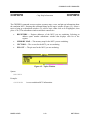
COMMAND-LINE COMMANDS
BAUDCHK
Baud Rate Check
BAUDCHK
The BAUDCHK command checks communication at 57600 baud and successively lower rates to
determine the maximum available baud rate for a host computer.
Syntax:
BAUDCHK
Example:
>BAUDCHK
57600 baud communicates well
The command displays a message indicating the maximum available baud rate.
MMDS11OM/D
6-11
MOTOROLA
COMMAND-LINE COMMANDS
BELL
Sound Bell
BELL
The BELL command sounds the computer bell the specified hexadecimal number of times. The
bell sounds once if you do not enter an argument. To turn off the bell as it is sounding, press any
key.
Syntax:
BELL [<n>]
where:
<n>
The hexadecimal number of times to sound the bell.
Examples:
>BELL
>BELL C
>BELL 12
MMDS11OM/D
Sound the bell once.
Sound the bell 12 (decimal) times.
Sound the bell 18 (decimal) times.
6-12
MOTOROLA
COMMAND-LINE COMMANDS
BF
Block Fill
BF
The BF command fills a block of memory with a specified byte or word.
Syntax:
BF[.<length>] <range> <n>
where:
<length>
Size of <n>:
B
<n> is an 8-bit value (the default).
W
<n> is a 16-bit value.
<range>
A block (range) of memory defined by beginning and ending addresses,
$0000 to $FFFF.
<n>
A value to be stored in a byte or word of the specified block. If <n> is
an 8-bit value, it is stored in each byte of the block; if <n> is a 16-bit
value, it is stored in each word of the block.
Examples:
>BF 200 20F FF
>BF.W 100 11F 4143
MMDS11OM/D
Store FF hexadecimal in bytes at addresses 200  20F.
Store 4143 in words at addresses 100  11F.
6-13
MOTOROLA
COMMAND-LINE COMMANDS
BPROT
Block Protect Register
BPROT
The BPROT command lets you change the value of the BPROT register. Potentially, you may
use this command to change the values of the INIT, OPTION, TMSK2, and INIT2 registers, as
well.
If you enter this command with a <value> argument, the system accepts the value. Press the F7
key to reset the MCU; the reset writes the new value to the register.
If you enter the BPROT command without a <value> argument, the system displays the options
window (Figure 6-1). This window lists the values of the INIT, OPTION, TMSK2, BPROT, and
INIT2 registers. To change any value of the options window, highlight the value, then type in the
new value. Press the F7 key to reset the MCU; the reset writes the new values to the registers.
Pressing the ESC key when the window is open aborts register changes.
Figure 6-1. Options Window
Some MCUs do not have internal EEPROM that is remappable via an INIT2 register. For such
an emulation MCU, the options window does not list an INIT2 register.
Table 6-4 lists definitions for all the options-window registers. To change the value of one of the
other registers, you may enter an INIT, OPTION, TMSK2, or INIT2 command with a <value>
argument. As with BPROT, entering one of these commands without a <value> argument brings
up the options window. Via this window, you can change the values of any register, including
BPROT.
MMDS11OM/D
6-14
MOTOROLA
COMMAND-LINE COMMANDS
BPROT
BPROT
Block Protect Register
Table 6-4. Options Window Registers
NAME
DEFINITION
ADDRESS
INIT
RAM and I/O Mapping Register
$X03D
OPTION
System Configuration Options
$X039
TMSK2
Timer Interrupt Mask Register 2
$X024
BPROT
Block Protect Register
$X035
INIT2 (1)
EEPROM Mapping Register
$X037
(1) Appears only if the emulation MCU has internal EEPROM
remappable via an INIT2 register.
For most HC11 devices, you must clear the BPROT register before programming EEPROM.
Once you clear the BPROT register bits, the MM or MD commands automatically erase and
reprogram the EEPROM. Optionally, you may download directly into EEPROM.
Syntax:
BPROT [<value>]
where:
<value >
A hexadecimal BPROT register value.
Examples:
>BPROT 1F
>BPROT
MMDS11OM/D
Change the BPROT register value to 1F (after a reset).
Display the options window (for changing any of five register values).
6-15
MOTOROLA
COMMAND-LINE COMMANDS
BR
Set Instruction Breakpoint
BR
The BR command sets an instruction breakpoint at a specified address or range of addresses. The
maximum number of all instruction breakpoints is 64. For a list of all active breakpoints, enter
this command without any parameter value.
A breakpoint occurs only on an address that contains an instruction (that is, an instruction fetch
address). Although this command sets breakpoints at each address of a range, breakpoints occur
only at the instruction fetch addresses within the range. The system displays an error message if
the address is within the range defined by a previous BR command, or if the range of a new BR
command overlaps the range of an existing BR command. An error message also appears if you
attempt to set a 65th breakpoint.
Syntax:
BR [<address>|<range>]
where:
<address >
The address for a breakpoint.
<range>
The range of addresses for breakpoints: a beginning address and an
ending address, separated by a space.
Examples:
>BR 100
>BR 1000 103F
MMDS11OM/D
Set a breakpoint at address 100.
Set 64 breakpoints, at addresses 1000 through 103F. Note that
trying to set additional breakpoints, without clearing some of
these breakpoints, would bring up the error message:
Too many breakpoints
6-16
MOTOROLA
COMMAND-LINE COMMANDS
C
C
Set/Clear C Bit
The C command sets the C bit of the condition code register (CCR) to the specified value.
NOTE
The CCR bit designators are at the lower right of the CPU window. The CCR
pattern is SXHINZVC (S is stop disable, X is XIRQ interrupt mask, H is halfcarry, I is IRQ interrupt mask, N is negative, Z is zero, V is overflow, and C is
carry). A letter in these designators means that the corresponding bit of the CCR is
set; a period means that the corresponding bit is clear.
Syntax:
C 0|1
where:
0
Clears the C bit
1
Sets the C bit
Example:
>C 0
MMDS11OM/D
Clear the C bit of the CCR.
6-17
MOTOROLA
COMMAND-LINE COMMANDS
CCR
Set Condition Code Register
CCR
The CCR command sets the condition code register (CCR) to the specified hexadecimal value.
NOTE
The CCR bit designators are at the lower right of the CPU window. The CCR
pattern is SXHINZVC (S is stop disable, X is XIRQ interrupt mask, H is halfcarry, I is IRQ interrupt mask, N is negative, Z is zero, V is overflow, and C is
carry). A letter in these designators means that the corresponding bit of the CCR is
set; a period means that the corresponding bit is clear.
Syntax:
CCR <n>
where:
<n>
The new hexadecimal value for the CCR.
Example:
>CCR E4
MMDS11OM/D
Set the CCR to E4 (S, X, H, and Z bits set, others clear).
6-18
MOTOROLA
COMMAND-LINE COMMANDS
CHIPINFO
Chip Help Information
CHIPINFO
The CHIPINFO command accesses register, memory-map, vector, and pin-out information about
the emulation MCU. Entering this command brings up the topics window (Figure 6-2). Select a
topic to bring up a subordinate window. (To select a topic, either click on it or highlight it, then
press <CR>.) The subordinate windows and their contents are:
•
REGISTERS  Register addresses of the MCU you are emulating. Selecting an
address opens another subordinate window that displays each bit of the
register.
•
MEMORY MAP  The memory map for the MCU you are emulating.
•
VECTORS  The vectors for the MCU you are emulating.
•
PIN OUT  The pin outs for the MCU you are emulating.
Figure 6-2. Topics Window
Syntax:
CHIPINFO
Example:
>CHIPINFO
MMDS11OM/D
Access emulation MCU information.
6-19
MOTOROLA
COMMAND-LINE COMMANDS
CLEARMAP
Remove Symbols
CLEARMAP
The CLEARMAP command removes the symbol definitions in the host computer.
Syntax:
CLEARMAP
Example:
>CLEARMAP
MMDS11OM/D
Clear symbols and their definitions.
6-20
MOTOROLA
COMMAND-LINE COMMANDS
COLORS
Set Screen Colors
COLORS
The COLORS command sets the screen colors. Entering this command brings up the colors
window. This window includes a list of screen elements and a matrix of foreground/background
color combinations; each color combination has a two-digit hexadecimal number.
A prompt asks for the color of the first screen element. To accept the current color, press <CR>.
To change the color, enter the number of your choice, then press <CR>. A new prompt asks for
the color of the next element. Select the color for each element in the same way. The command
ends when you select a color for the last screen element, or when you press ESC.
In the color matrix, rows correspond to background colors, and columns correspond to
foreground colors. This means that color choices from the same row result in differently colored
letters and numbers against the same background color. Making the background of highlights and
help screens a different color sets these elements off from the main screen.
The software stores color selections in file COLORS.11; when you execute MMDS11 again the
software applies the newly selected colors
NOTE
Delete the COLORS.11 file from the \MMDS11 subdirectory to return to the
default colors.
Syntax:
COLORS
MMDS11OM/D
6-21
MOTOROLA
COMMAND-LINE COMMANDS
D
Set Accumulator D
D
The D command sets the D accumulator to a specified value. The D accumulator is a
concatenation of the A accumulator and the B accumulator.
Syntax:
D <n>
where:
<n>
The value to be loaded into the D accumulator.
Example:
>D 1234
MMDS11OM/D
Set accumulator D to 1234.
6-22
MOTOROLA
COMMAND-LINE COMMANDS
DARM
Disarm Bus State Analyzer
DARM
The DARM command disarms the bus state analyzer. When disarmed, the analyzer does not
record bus cycles. The word Disarmed appears in the status area of the debug screen. (If the
bus state analyzer is already disarmed, this command does nothing.)
Syntax:
DARM
Example:
>DARM
MMDS11OM/D
Disarm the bus state analyzer.
6-23
MOTOROLA
COMMAND-LINE COMMANDS
DASM
Disassemble Instructions
DASM
The DASM command disassembles three or more machine instructions, displaying the addresses
and the contents as disassembled instructions. Disassembly begins at the specified address. The
valid address range is $0000 to $FFFF.
Syntax:
DASM <address1> [<address2>]
where:
<address1>
The starting address for disassembly. <Address1> must be an
instruction opcode. If you enter only an <address1> value, the system
disassembles three instructions.
<address2>
The ending address for disassembly. If you enter an <address2> value,
disassembly begins at <address1> and continues through
<address2>. The screen scrolls upward as addresses and their contents
are displayed, leaving the last instructions in the range displayed in the
window.
Example: disassemble and display three instructions, beginning at address 100:
>DASM 100
0100
0101
0104
MMDS11OM/D
01
FF8FDD
D7DA
NOP
STX 8FDD
STAB 00DA
6-24
MOTOROLA
COMMAND-LINE COMMANDS
EMUBP
Set Breakpoint Bank Comparator
EMUBP
The EMUBP command sets the breakpoint bank comparator match value. The breakpoint
comparator (BPX) checks the breakpoint bank match value against the data on the extension
address lines XA16  XA19. When these lines equal the breakpoint match value, instruction
breakpoints are enabled (BPX = 1). BPX may be used in a term to trigger the bus state analyzer.
Power-up or a system reset clears the comparator (that is, gives it the value zero) and pulls XA16
 XA19 low. This enables the breakpoints in bank $0.
Syntax:
EMUBP <n>
where:
<n>
A four-bit hexadecimal value.
Example:
>EMUBP 5
MMDS11OM/D
Write $5 to the breakpoint bank comparator.
6-25
MOTOROLA
COMMAND-LINE COMMANDS
EMURAM
Set Emulation RAM Bank Comparator
EMURAM
The EMURAM command sets the emulation RAM bank comparator match value. The emulation
RAM comparator (ERX) checks the emulation RAM bank match value against the data on
extension address lines XA16  XA19. When these lines equal the emulation RAM match
value, instruction breakpoints are enabled (ERX = 1). ERX may be used in a term to trigger the
bus state analyzer. Power-up or a system reset clears the comparator (that is, gives it the value
zero) and pulls XA16  XA19 low. This enables the emulation RAM in bank $0.
Syntax:
EMURAM <n>
where:
<n>
A four-bit hexadecimal value.
Example:
>EMURAM C
MMDS11OM/D
Write $C to the emulation RAM bank comparator.
6-26
MOTOROLA
COMMAND-LINE COMMANDS
ENDBSA
Go to Trace Buffer End
ENDBSA
The ENDBSA command shows end-of-buffer data in the data screen when you return to the BSA
data screen (F5).
Syntax:
ENDBSA
Example:
>ENDBSA
MMDS11OM/D
Show end-of-buffer data in the data screen.
6-27
MOTOROLA
COMMAND-LINE COMMANDS
EVAL
Evaluate Argument
EVAL
The EVAL command displays the value of the operand in hexadecimal, decimal, octal, and
binary formats, denoted by the suffixes H, T, O, and Q. (Note that octal numbers are not valid as
operand values. Operand values are 16 bits or less.) If the value is printable, this command also
displays the value in ASCII characters. The operand can be a number or the sequence number,
space, operator, space, and number. This command supports addition (+), subtraction (-),
multiplication (*) and division (/).
Syntax:
EVAL <n1> [<op> <n2>]
where:
<n1>
A number to be evaluated, or the first operand of a simple expression to
be evaluated.
<op>
The arithmetic operator (+, -, *, or /) of a simple expression to be
evaluated.
<n2>
The second operand of a simple expression to be evaluated.
Example: evaluate the sum of hexadecimal numbers 45 and 32, then display the result in four
bases, and as an ASCII character:
>EVAL 45 + 32
0077H 119T 000167O 0000000001110111Q "w"
MMDS11OM/D
6-28
MOTOROLA
COMMAND-LINE COMMANDS
EXIT
Terminate Host Session
EXIT
The EXIT command terminates the host session and returns to DOS. (The EXIT and QUIT
commands are identical. Another way to end a host session is to enter the ALT-X keyboard
combination.)
Syntax:
EXIT
Example:
>EXIT
MMDS11OM/D
Return to DOS.
6-29
MOTOROLA
COMMAND-LINE COMMANDS
EXPANDED
Set MCU Operating Mode to Expanded
EXPANDED
The EXPANDED command sets the MCU operating mode to expanded. This command works
only if the MCU mode is set to user selectable by the MODE command. Related commands are
SINGLECHIP, SPECIALBOOT, and SPECIALTEST.
Some HC11 emulator modules (EMs) do not let you select (from the host) the polarity of
MODEB. This limits operation to single-chip or expanded mode. If you enter the target value
with the MODE command, the target selects any MCU operating mode on powerup or reset. The
special bootstrap mode is emulated in special test mode with the PRU enabled. The bootstrap
firmware may be loaded into emulation RAM and the RESETGO command issued by a script
file.
NOTE
The current hardware does not let you switch from special boot or special test to
single chip or expanded by writing to the MDA bit of the HPRIO register. Mode
selection takes effect only upon powerup or reset.
Syntax:
EXPANDED
Example:
>EXPANDED
Set the MCU to expanded mode.
>MODE
Display the current mode.
MODE: USER SELECTED - Expanded
>
MMDS11OM/D
6-30
MOTOROLA
COMMAND-LINE COMMANDS
G
G
Begin Program Execution
The G command starts execution of code in the emulator at the current address or at a specified
address. If you enter one address, it is the starting address. If you enter two addresses, execution
begins at the first and stops at the second. (The G and GO commands are identical.)
If you specify only one address, execution continues until you enter a STOP command, a
breakpoint occurs, a trigger condition set to stop execution in the analyzer occurs, or an error
occurs.
Syntax:
G [<address1>] [<address2>]
where:
<address1>
Execution starting address. If you enter an <address1> value, the
system loads the value into the program counter (PC), then starts
execution at the address in the PC. If you do not enter an <address1>
value, execution begins at the address already in the PC.
<address2>
Execution stop address. The <address2> value must be an instruction
fetch address; if it is not, code execution continues as if the command
had no <address2> value.
NOTE
Be careful about using the G, GO, or GOTIL commands if the PC points to
internal RAM or EEPROM (or if the code branches into internal RAM or
EEPROM). In these situations, the STOP command does not work unless the
CCR I bit is clear. If you do want to execute out of internal RAM or EEPROM,
clear the I bit before you enter the execution command.
Example:
>G
>G 146
>G 200 271
>G A000 LOOP
MMDS11OM/D
Begin code execution at the current PC value.
Begin code execution at address 146.
Begin code execution at address 200. End code execution just before
the instruction at address 271.
Begin code execution at address A000. End code execution just
before the LOOP instruction.
6-31
MOTOROLA
COMMAND-LINE COMMANDS
GETBSA
Upload Trace Buffer
GETBSA
The GETBSA command uploads the contents of the bus state analyzer trace buffer to the host
computer. This is convenient when using a script file in conjunction with the bus state analyzer.
Syntax:
GETBSA
Example:
>GETBSA
MMDS11OM/D
Upload trace buffer contents to the host computer.
6-32
MOTOROLA
COMMAND-LINE COMMANDS
GO
GO
Begin Program Execution
The GO command starts execution of code in the emulator at the current address or at a specified
address. If you enter one address, it is the starting address. If you enter two addresses, execution
begins at the first and stops at the second. (The GO and G commands are identical.)
If you specify only one address, execution continues until you enter a STOP command, a
breakpoint occurs, a trigger condition set to stop execution in the analyzer occurs, or an error
occurs.
Syntax:
GO [<address1>] [<address2>]
where:
<address1>
Execution starting address. If you enter an <address1> value, the
system loads the value into the program counter (PC), then starts
execution at the address in the PC. If you do not enter an <address1>
value, execution begins at the address already in the PC.
<address2>
Execution stop address. The <address2> value must be an instruction
fetch address; if it is not, code execution continues as if the command
had no <address2> value.
NOTE
Be careful about using the GO, GOTIL, or G commands if the PC points to
internal RAM or EEPROM (or if the code branches into internal RAM or
EEPROM). In these situations, the STOP command does not work unless the
CCR I bit is clear. If you do want to execute out of internal RAM or EEPROM,
clear the I bit before you enter the execution command.
Example:
>GO
>GO 232
>GO 100 171
MMDS11OM/D
Begin code execution at the current PC value.
Begin code execution at address 232.
Begin code execution at address 100. End code execution just
before the instruction at address 171.
6-33
MOTOROLA
COMMAND-LINE COMMANDS
GOTIL
Execute Program until Address
GOTIL
The GOTIL command executes the program in the emulator, beginning at the address in the
program counter (PC). Execution continues until the program counter contains the specified
address.
Syntax:
GOTIL <address>
where:
<address>
Execution stop address. The <address> value must be an instruction
fetch address; if it is not, code execution continues as if the command
had no <address> value.
NOTE
Be careful about using the GOTIL, G, or GO commands if the PC points to
internal RAM or EEPROM (or if the code branches into internal RAM or
EEPROM). In these situations, the STOP command does not work unless the
CCR I bit is clear. If you do want to execute out of internal RAM or EEPROM,
clear the I bit before you enter the execution command.
Example:
>GOTIL 0FF0
MMDS11OM/D
Execute the program in the emulator up to address 0FF0.
6-34
MOTOROLA
COMMAND-LINE COMMANDS
H
H
Set/Clear H Bit
The H command sets the H bit of the condition code register (CCR) to the specified value.
NOTE
The CCR bit designators are at the lower right of the CPU window. The CCR
pattern is SXHINZVC (S is stop disable, X is XIRQ interrupt mask, H is halfcarry, I is IRQ interrupt mask, N is negative, Z is zero, V is overflow, and C is
carry). A letter in these designators means that the corresponding bit of the CCR is
set; a period means that the corresponding bit is clear.
Syntax:
H 0|1
where:
0
Clears the H bit
1
Sets the H bit
Example:
>H 1
MMDS11OM/D
Set the H bit of the CCR.
6-35
MOTOROLA
COMMAND-LINE COMMANDS
HELP
Display Help Information
HELP
The HELP command displays a list of help topics: commands, bus state analyzer, and function
keys.
If you select commands, the software displays an alphabetic index of command names from
which you can select a command. The command description screen shows the command name
and its syntax and describes the command. When appropriate, the description includes examples
and clarifying notes.
Selecting bus state analyzer brings up a description of bus state analyzer operation.
Selecting function keys brings up a list of screens in which function-key assignments differ.
Select a screen to see its function-key assignments.
Use the arrow keys to scroll within the page; use the page up and page down keys to see other
pages.
To exit the HELP database and return to the previous screen, press the ESC key.
Syntax:
HELP [<command>]
where:
<command>
Name of a command for which a description is needed.
Example:
>HELP
>HELP ASM
Display the HELP screens.
Display the description of the ASM command.
Related Key Command:
F1 while in DEBUG window or bus state analyzer setup window.
MMDS11OM/D
6-36
MOTOROLA
COMMAND-LINE COMMANDS
HOMEBSA
Go to Trace Buffer Start
HOMEBSA
The HOMEBSA command shows start-of-buffer data in the data screen when you return to the
BSA data screen (F5).
Syntax:
HOMEBSA
Example:
>HOMEBSA
MMDS11OM/D
Show start-of-buffer data in the data screen upon return to the BSA data
screen.
6-37
MOTOROLA
COMMAND-LINE COMMANDS
I
I
Set/Clear I Bit
The I command sets the I bit of the condition code register (CCR) to the specified value.
NOTE
The CCR bit designators are at the lower right of the CPU window. The CCR
pattern is SXHINZVC (S is stop disable, X is XIRQ interrupt mask, H is halfcarry, I is IRQ interrupt mask, N is negative, Z is zero, V is overflow, and C is
carry). A letter in these designators means that the corresponding bit of the CCR is
set; a period means that the corresponding bit is clear.
Syntax:
I 0|1
where:
0
Clears the I bit
1
Sets the I bit
Example:
>I 1
MMDS11OM/D
Set the I bit of the CCR.
6-38
MOTOROLA
COMMAND-LINE COMMANDS
INFO
INFO
Display Line Information
The INFO command displays information about the highlighted line in the source F2 window.
This information includes the name of the file being displayed in the window, the line number,
address, corresponding object code, and the disassembled instruction.
Syntax:
INFO
Example:
>INFO
Filename
Address
Disassembly
MMDS11OM/D
Display information about the highlighted line.
:
11TESTCO.ASM
Line number
:
$A700
:
A700 0D
SEC
6-39
:
117
MOTOROLA
COMMAND-LINE COMMANDS
INIT
Set RAM and I/O Mapping Initialization Register
INIT
The INIT command lets you change the value of the INIT register. Potentially, you may use this
command to change the values of the OPTION, TMSK2, BPROT, and INIT2 registers, as well.
If you enter this command with a <value> argument, the system accepts the value. Press the F7
key to reset the MCU; the system writes the new value to the register.
If you enter the INIT command without a <value> argument, the system displays the options
window (Figure 6-3). This window lists the values of the INIT, OPTION, TMSK2, BPROT, and
INIT2 registers. To change any value of the options window, highlight the value, then type in the
new value. Press the F7 key to reset the MCU; the reset writes the new values to the registers.
Pressing the ESC key when the window is open aborts register changes.
Figure 6-3. Options Window
The INIT command updates the monitor with the address of RAM and I/O. The monitor uses this
information to update the COP register and perform EEPROM programming. This command
changes the mapping RAM to reconfigure the memory map to an internal resource at the address
of RAM and I/O.
Some MCUs do not have internal EEPROM that is remappable via an INIT2 register. For such
an emulation MCU, the options window does not list an INIT2 register.
Table 6-5 lists definitions for all the options-window registers. To change the value of one of the
other registers, you may enter a BPROT, OPTION, TMSK2, or INIT2 command with a <value>
argument. As with INIT, entering one of these commands without a <value> argument brings up
the options window. Via this window, you can change the values of any register, including INIT.
MMDS11OM/D
6-40
MOTOROLA
COMMAND-LINE COMMANDS
INIT
Set RAM and I/O Mapping Initialization Register
INIT
Table 6-5. Options Window Registers
NAME
DEFINITION
ADDRESS
INIT
RAM and I/O Mapping Register
$X03D
OPTION
System Configuration Options
$X039
TMSK2
Timer Interrupt Mask Register 2
$X024
BPROT
Block Protect Register
$X035
INIT2 (1)
EEPROM Mapping Register
$X037
(1) Appears only if the emulation MCU has internal EEPROM
remappable via an INIT2 register.
Syntax:
INIT [<value>]
where:
<value >
A hexadecimal INIT register value.
Example:
>INIT
MMDS11OM/D
Display the options window (for changing any of five register values).
6-41
MOTOROLA
COMMAND-LINE COMMANDS
INIT2
Set EEPROM Mapping Initialization Register
INIT2
The INIT2 command lets you change the value of the INIT2 register. Potentially, you may use
this command to change the values of the INIT, OPTION, TMSK2, and BPROT registers, as
well.
If you enter this command with a <value> argument, the system accepts the value. Press the F7
key to reset the MCU; the system writes the new value to the register.
If you enter the INIT2 command without a <value> argument, the system displays the options
window (Figure 6-4). This window lists the values of the INIT, OPTION, TMSK2, BPROT, and
INIT2 registers. To change any value of the options window, highlight the value, then type in the
new value. Press the F7 key to reset the MCU; the reset writes the new values to the registers.
Pressing the ESC key when the window is open aborts register changes.
NOTE
Some MCUs do not have internal EEPROM remappable via an INIT2 register.
For such an MCU, the INIT2 command with a <value> argument has no effect.
For such an MCU, the INIT2 command without a <value> argument brings up
the options window, letting you change values of the other registers.
Figure 6-4. Options Window
The INIT2 command updates the monitor with the address of EEPROM. The monitor uses this
information to update the COP register and perform EEPROM programming. This command
changes the mapping RAM to reconfigure the memory map to an internal resource at the address
of EEPROM.
MMDS11OM/D
6-42
MOTOROLA
COMMAND-LINE COMMANDS
INIT2
Set EEPROM Mapping Initialization Register
INIT2
Table 6-6 lists definitions for all the options-window registers. To change the value of one of the
other registers, you may enter an INIT, OPTION, TMSK2, or BPROT command with a <value>
argument. As with INIT2, entering one of these commands without a <value> argument brings
up the options window. Via this window, you can change the values of any register, including
INIT2.
Table 6-6. Options Window Registers
NAME
DEFINITION
ADDRESS
INIT
RAM and I/O Mapping Register
$X03D
OPTION
System Configuration Options
$X039
TMSK2
Timer Interrupt Mask Register 2
$X024
BPROT
Block Protect Register
$X035
INIT2 (1)
EEPROM Mapping Register
$X037
(1) Appears only if the emulation MCU has internal EEPROM
remappable via an INIT2 register.
Syntax:
INIT2 [<value>]
where:
<value >
A hexadecimal INIT2 register value.
Example:
>INIT2
MMDS11OM/D
Display the options window (for changing any of five register values).
6-43
MOTOROLA
COMMAND-LINE COMMANDS
LF
Log File
LF
The LF command starts or stops logging of commands and responses to an external file. If
logging is not enabled, enter this command to start logging. While logging remains in effect, any
line that is appended to the command log window is also written to the log file. Logging
continues until you enter another LF command; this second command disables logging and
closes the log file.
If the specified file does not already exist, this command creates the file. If the specified file does
exist already, the command prompts for overwrite or append:
File exists, Rewrite or Append? [R]:
If you press <CR> (accept the default), or R and <CR>, the log entries overwrite the data in the
existing file. If you press A and <CR>, the system appends log entries to the file.
Syntax:
LF <filename>
where:
<filename>
The DOS filename of the log file. The command interpreter does not
assume a filename extension.
Examples:
>LF logfile
>LF
MMDS11OM/D
Start logging. Write to file logfile (in the current directory) all
lines added to the command log window.
(If logging is enabled): Disable logging and close the log file.
6-44
MOTOROLA
COMMAND-LINE COMMANDS
LOAD
Load S19 File
LOAD
The LOAD command loads a file in .S19 format (and any map file with the same name) into the
emulator.
Syntax:
LOAD <filename>
where:
<filename>
The name of the .S19 file to be loaded; the .S19 extension is optional.
You can enter a pathname followed by the asterisk (*) wildcard
character. In that case, the command displays a window that lists the
files in the specified directory that have the .S19 extension.
Examples:
>LOAD PROG1.S19
>LOAD PROG2
>LOAD A:*
MMDS11OM/D
Load file PROG1.S19 and its map file into the emulator at
the load addresses in the file.
Load file PROG2.S19 and its map file into the emulator at
the load addresses in the file.
Display the names of the .S19 files on the diskette in
drive A:, for user selection of a file.
6-45
MOTOROLA
COMMAND-LINE COMMANDS
LOADMAP
Load Symbols
LOADMAP
The LOADMAP command loads a map file that contains source level debug information into the
host computer. The command requests an appropriate filename.
Syntax:
LOADMAP <filename>
where:
<filename>
The name of the map file to be loaded; the .MAP extension is optional.
You can enter a pathname followed by the asterisk (*) wildcard
character. In that case, the command displays a window that lists the
files in the specified directory that have the .MAP extension.
Examples:
>LOADMAP PROG1.MAP
>LOADMAP PROG2
>LOADMAP A:*
MMDS11OM/D
Load map file PROG1.MAP into the host computer.
Load map file PROG2.MAP into the host computer.
Display the names of the .MAP files on the diskette in
drive A:, for user selection of a file.
6-46
MOTOROLA
COMMAND-LINE COMMANDS
LOADMEM
Load Personality File
LOADMEM
The LOADMEM command loads the memory map for the emulator with the map information
from the specified file.
Syntax:
LOADMEM <filename>
where:
<filename>
The name of the memory-mapping file to be loaded: a personality or
.MEM file written by pressing the F6 key in the SETMEM window. The
.MEM extension is optional. You can enter a pathname followed by the
asterisk (*) wildcard character. In that case, the command displays a
window that lists the files in the specified directory that have the .MEM
extension.
Examples:
>LOADMEM 10001V01.MEM
>LOADMEM 01FF
>LOADMEM A:*
MMDS11OM/D
Make file 10001V01.MEM the current memorymapping file.
Make file 01FF.MEM the current memorymapping file.
Display the names of the .MEM files on the
diskette in drive A:, for user selection of a file.
6-47
MOTOROLA
COMMAND-LINE COMMANDS
LOADTRIGGERS
Load Bus State Analyzer Setup
LOADTRIGGERS
The LOADTRIGGERS command loads the bus state analyzer setup information from the
specified file. To write such a file, use the bus state analyzer setup screen to define the triggers,
then press the F6 key.
Syntax:
LOADTRIGGERS <filename>
where:
<filename>
The name of the setup file to be loaded; the .SET extension is optional.
You can enter a pathname followed by the asterisk (*) wildcard
character. In that case, the command displays a window that lists the
files in the specified directory that have the .SET extension.
Example:
>LOADTRIGGERS BSA.SET
>LOADTRIGGERS BSA8
>LOADTRIGGERS A:*
MMDS11OM/D
Make file BSA.SET the current BSA setup file.
Make file BSA8.SET the current BSA setup file.
Display the names of the .SET files on the diskette
in drive A:, for user selection of a file.
6-48
MOTOROLA
COMMAND-LINE COMMANDS
MD
MD
Memory Display
The MD command displays (in the memory F3 window) the contents of 32 emulation memory
locations. The specified address is the first of the 32 locations. If a log file is open, this command
also writes the first 16 values to the log file.
Syntax:
MD <address>
where:
<address>
The starting memory address for display in the memory window.
Example:
>MD 1000
MMDS11OM/D
Display the contents of 32 bytes of memory beginning at address 1000.
6-49
MOTOROLA
COMMAND-LINE COMMANDS
MM
Memory Modify
MM
The MM command lets you interactively examine and modify contents of memory locations.
If you enter any values with this command, the system stores the values, beginning at the
specified address. If you do not enter a data value, the command displays the address and
prompts for a value to be stored at that address. You can modify and verify data according to the
command terminator:
[<data>]<CR>Update location and sequence forward.
[<data>]^<CR>
Update location and sequence backward.
[<data>]=<CR>
Update location and reopen the same location.
[<data>].<CR>
Update location and terminate.
The MM command displays consecutive addresses and prompts until you enter a period (.). This
command does not alter the contents of the program counter (PC).
Syntax:
MM <address>[<n> ...]
where:
<address>
The address of a memory location to be modified.
<n>
The value to be stored in the address.
Examples:
The first example does not have an <n> value in the command line, permitting entry of new
values for consecutive addresses. Entering a period instead of a new value stops the command:
>MM 1000
1000 = 0F >05
1001 = 10 >.
The second example includes an <n> value, so the command modifies only one memory
location:
>MM 100 00
MMDS11OM/D
6-50
MOTOROLA
COMMAND-LINE COMMANDS
MODE
Display/Select MCU Operating Mode
MODE
The MODE command displays or lets you select the input (target or user) that controls the MCU
operation mode. Entering this command without a parameter value displays the current control
mode.
Some HC11 emulator modules (EMs) do not let you select (from the host) the polarity of
MODEB. This limits operation to single-chip or expanded mode. If you enter the target value
with the MODE command, the target selects any MCU operating mode on powerup or reset. The
special bootstrap mode is emulated in special test mode with the PRU enabled. The bootstrap
firmware may be loaded into emulation RAM and the RESETGO command issued by a script
file.
NOTE
Current hardware does not let you switch from special boot or special test to
single chip or expanded by writing to the MDA bit of the HPRIO register. Mode
selection takes effect only upon powerup or reset.
Syntax:
MODE [user|target]
where:
user
Lets you set the MCU operating mode; the default value for the MODE
command. In this user mode, you may enter single-chip, expanded,
special-boot, or special-test commands.
target
Lets the target set the MCU operating mode. Before you enter singlechip, expanded, special-boot, or special-test commands, you must
change from this target mode to user mode.
Examples:
>MODE
MODE:
>
>MODE
MODE:
>
>MODE
MODE:
Display the current mode.
USER SELECTED - Expanded
TARGET
Let the target set the operating mode.
TARGET SELECTED
USER
Let the user set the operating mode via the keyboard.
USER SELECTED - Single Chip
(Shows current mode.)
MMDS11OM/D
6-51
MOTOROLA
COMMAND-LINE COMMANDS
N
N
Set/Clear N Bit
The N command sets the N bit of the condition code register (CCR) to the specified value.
NOTE
The CCR bit designators are at the lower right of the CPU window. The CCR
pattern is SXHINZVC (S is stop disable, X is XIRQ interrupt mask, H is halfcarry, I is IRQ interrupt mask, N is negative, Z is zero, V is overflow, and C is
carry). A letter in these designators means that the corresponding bit of the CCR is
set; a period means that the corresponding bit is clear.
Syntax:
N 0|1
where:
0
Clears the N bit
1
Sets the N bit
Example:
>N 1
MMDS11OM/D
Set the N bit of the CCR.
6-52
MOTOROLA
COMMAND-LINE COMMANDS
NEXTA
Go to Next A Event
NEXTA
The NEXTA command positions the bus state analyzer display at the next occurrence of an A
event. If a log file is open, this command also writes that frame to the log file.
Syntax:
NEXTA
Example:
>NEXTA
Scroll the bus state analyzer display to the next A event.
Related Key Command:
Alt-A while in bus state analyzer data window.
MMDS11OM/D
6-53
MOTOROLA
COMMAND-LINE COMMANDS
NEXTB
Go to Next B Event
NEXTB
The NEXTB command positions the bus state analyzer display at the next occurrence of a B
event. If a log file is open, this command also writes that frame to the log file.
Syntax:
NEXTB
Example:
>NEXTB
Scroll the bus state analyzer display to the next B event.
Related Key Command:
Alt-B while in the bus state analyzer data window.
MMDS11OM/D
6-54
MOTOROLA
COMMAND-LINE COMMANDS
NEXTC
Go to Next C Event
NEXTC
The NEXTC command positions the bus state analyzer display at the next occurrence of a C
event. If a log file is open, this command also writes that frame to the log file.
Syntax:
NEXTC
Example:
>NEXTC
Scroll the bus state analyzer display to the next C event.
Related Key Command:
Alt-C while in the bus state analyzer data window.
MMDS11OM/D
6-55
MOTOROLA
COMMAND-LINE COMMANDS
NEXTD
Go to Next D Event
NEXTD
The NEXTD command positions the bus state analyzer display at the next occurrence of a D
event. If a log file is open, this command also writes that frame to the log file.
Syntax:
NEXTD
Example:
>NEXTD
Scroll the bus state analyzer display to the next D event.
Related Key Command:
Alt-D while in the bus state analyzer data window.
MMDS11OM/D
6-56
MOTOROLA
COMMAND-LINE COMMANDS
NEXTE
Go to Next Event
NEXTE
The NEXTE command positions the bus state analyzer display at the next occurrence of any
event. If a log file is open, this command also writes that frame to the log file.
Syntax:
NEXTE
Example:
>NEXTE
Scroll the bus state analyzer display to the next event.
Related Key Command:
Alt-E while in the bus state analyzer data window.
MMDS11OM/D
6-57
MOTOROLA
COMMAND-LINE COMMANDS
NOBR
Clear Breakpoints
NOBR
The NOBR command clears one instruction breakpoint, all instruction breakpoints, or all
instruction breakpoints within an address range. If this command has one address value, it clears
the breakpoint at that address. If this command has no address value, it clears all current
breakpoints. If this command has two address values, it clears all instruction breakpoints in the
range the addresses define.
Syntax:
NOBR [<address1> <address2>]
where:
<address1>
If the only address value, the address of the single breakpoint to be
removed. If the first of two address values, the beginning of the address
range from which all breakpoints are to be removed.
<address2>
The last address of the range from which all breakpoints are to be
removed.
Examples:
>NOBR
>NOBR A051
>NOBR A000 A010
MMDS11OM/D
Clear all current instruction breakpoints.
Clear the instruction breakpoint at address $A051.
Clear all instruction breakpoints in the address range
$A000 to $A010.
6-58
MOTOROLA
COMMAND-LINE COMMANDS
OPTION
Set the System Configuration Options Register
OPTION
The OPTION command lets you change the value of the OPTION register. Potentially, you may
use this command to change the values of the INIT, TMSK2, BPROT, and INIT2 registers, as
well.
If you enter this command with a <value> argument, the system accepts the value. Press the F7
key to reset the MCU; the system writes the new value to the register.
If you enter the OPTION command without a <value> argument, the system displays the options
window (Figure 6-5). This window lists the values of the INIT, OPTION, TMSK2, BPROT, and
INIT2 registers. To change any value of the options window, highlight the value, then type in the
new value. Press the F7 key to reset the MCU; the reset writes the new values to the registers.
Pressing the escape ESC key when the window is open aborts register changes.
Figure 6-5. Options Window
Some MCUs do not have internal EEPROM that is remappable via an INIT2 register. For such
an emulation MCU, the options window does not list an INIT2 register.
Table 6-7 lists definitions for all the options-window registers. To change the value of one of the
other registers, you may enter a BPROT, INIT, INIT2, or TMSK2 command with a <value>
argument. As with OPTIONS, entering one of these commands without a <value> argument
brings up the options window. Via this window, you can change the values of any register,
including OPTION.
MMDS11OM/D
6-59
MOTOROLA
COMMAND-LINE COMMANDS
OPTION
Set the System Configuration Options Register
OPTION
Table 6-7. Options Window Registers
NAME
DEFINITION
ADDRESS
INIT
RAM and I/O Mapping Register
$X03D
OPTION
System Configuration Options
$X039
TMSK2
Timer Interrupt Mask Register 2
$X024
BPROT
Block Protect Register
$X035
INIT2 (1)
EEPROM Mapping Register
$X037
(1) Appears only if the emulation MCU has internal EEPROM
remappable via an INIT2 register.
Syntax:
OPTION [<value>]
where:
<value >
A hexadecimal OPTION register value.
Example:
>OPTION
MMDS11OM/D
Display the options window (for changing any of five register values).
6-60
MOTOROLA
COMMAND-LINE COMMANDS
OSC
Select Emulator Clock Frequency
OSC
The OSC command selects the clock frequency and source. Five internally-generated clock
frequencies are available: 16 Mhz, 8 Mhz, 4 Mhz, 2 Mhz, and 1 Mhz. Alternatively, you can use
an external clock signal supplied to the MMDS11 through pod A logic clip 9 (white). (When
using the logic clip cables, attach the black clip to ground.) Refer to the EM user’s manual for
EM clock information.
The default emulator clock rate is 8 MHz. Before changing the clock rate, make sure that your
emulation MCU is specified to run at the new rate.
Entering this command without the <rate> argument brings up the EM oscillator window. You
can select a frequency or source via this window.
Syntax:
OSC [<rate>]
where:
<rate>
16, 8, 4, 2, 1, or External.
Examples:
>OSC 4
>OSC External
>OSC
MMDS11OM/D
Use the 4 Mhz internal emulator clock.
Use an external emulator clock.
Bring up the emulator clock window.
6-61
MOTOROLA
COMMAND-LINE COMMANDS
PC
Set Program Counter
PC
The PC command sets the program counter (PC) to the specified address.
Syntax:
PC <address>
where:
<address>
The new address value for the PC.
Example:
>PC 0500
MMDS11OM/D
Set the PC to 0500.
6-62
MOTOROLA
COMMAND-LINE COMMANDS
QUIT
Terminate Host Session
QUIT
The QUIT command terminates the host session and returns to DOS. (The QUIT and EXIT
commands are identical. Another way to end a host session is to enter the ALT-X keyboard
combination.)
Syntax:
QUIT
Example:
>QUIT
MMDS11OM/D
Return to DOS.
6-63
MOTOROLA
COMMAND-LINE COMMANDS
REG
REG
Display Registers
The REG command displays the contents of the CPU registers in the debug F10 window.
Syntax:
REG
Example:
>REG
MMDS11OM/D
Display the contents of the CPU registers.
6-64
MOTOROLA
COMMAND-LINE COMMANDS
REM
Add Comment to Script File
REM
The REM command adds a display comment to a script file. When you execute the script file, the
system displays this comment.
Syntax:
REM <text>
where:
<text>
The display comment. You need not enclose <text> in quotes; pressing
<CR> terminates <text>.
Example:
>REM Program executing.
MMDS11OM/D
Display Program
script file execution.
6-65
executing only during
MOTOROLA
COMMAND-LINE COMMANDS
RESET
Reset Emulation MCU
RESET
The RESET command resets the emulation MCU and sets the program counter to the contents of
the reset vector. This command does not start execution of user code. To reset and execute user
code, use the RESETGO or WAIT4RESET command.
Syntax:
RESET
Example:
>RESET
MMDS11OM/D
Reset the MCU.
6-66
MOTOROLA
COMMAND-LINE COMMANDS
RESETGO
Reset and Restart MCU
RESETGO
The RESETGO command resets the emulation MCU, sets the program counter (PC) to the
contents of the reset vector, then starts execution from that address.
Syntax:
RESETGO
Example:
>RESETGO
MMDS11OM/D
Reset the MCU and go.
6-67
MOTOROLA
COMMAND-LINE COMMANDS
RESETIN
Reset Input Enable
RESETIN
The RESETIN command makes it possible for the target system to reset the emulating MCU.
Entering this command toggles the MMDS11 state with regard to a reset signal from the target
system. If this state is enabled, a reset signal from the target system resets the emulating MCU. If
this state is disabled, a reset signal from the target system cannot reset the emulating MCU. (The
word Resetin appears in the debug screen status area to show the enabled state.)
The state must be enabled for proper operation of the WAIT4RESET command.
Syntax:
RESETIN
Example:
>RESETIN
MMDS11OM/D
Toggle the MMDS11 RESETIN state.
6-68
MOTOROLA
COMMAND-LINE COMMANDS
RESETOUT
Reset Output Enable
RESETOUT
The RESETOUT command makes it possible for the MMDS11 RESET command to reset the
target system.
Entering this command toggles the MMDS11 state with regard to resetting the target system. If
this state is enabled, entering the RESET command resets both the emulating MCU and the target
system. If this state is disabled, entering the RESET command resets only the emulating MCU.
(The word Resetout appears in the debug screen status area to show the enabled state.)
The RESETOUT command also pertains to resets done via the RESETGO command.
Syntax:
RESETOUT
Example:
>RESETOUT
MMDS11OM/D
Toggle the MMDS11 RESETOUT state.
6-69
MOTOROLA
COMMAND-LINE COMMANDS
RTMEM
Set Real-Time Memory Block
RTMEM
The RTMEM command enables real-time-memory, starting at a specified address. The real-time
memory consists of 32 bytes of dual-ported memory that is assigned to any valid memory address
by this command. While the emulator is running, the system displays enabled real-time memory
in the real-time memory window (this window replaces the memory F3 window). The display
updates as the memory contents change. Entering the RTMEM command without an argument
disables real-time memory, restoring previous memory map attributes.
Real-time memory consists of memory enabled by the RTMEM command, plus real-time
variables created via the RTVAR command. All this real-time memory must fit within a 1K
block. If an RTMEM command would result in real-time memory that would not fit within the
1K block (due to established real-time variables), the system will not accept the RTMEM
command.
If any of the real-time memory overlays internal MCU I/O, RAM, or EEPROM addresses, it is
available only for monitoring emulation MCU writes. (You should not try to modify such
locations.) You can monitor and modify real-time memory locations that do not overlay internal
MCU I/O, RAM, or EEPROM addresses.
Syntax:
RTMEM [<address>]
where:
<address>
The beginning address of the real-time-memory.
Example:
>RTMEM 0200
MMDS11OM/D
Set the address of the real-time-memory to 0200 through 021F.
6-70
MOTOROLA
COMMAND-LINE COMMANDS
RTVAR
Display Real-Time Variable
RTVAR
The RTVAR command displays the specified address and its contents in the variables F8
window as a real-time variable.
As many as 32 variables can be available for display in the variables F8 window (although the
window shows 11 at a time). Using the RTVAR command establishes such variables as realtime: their values change in the variables F8 window during emulation. You can also enter a new
value for a real-time variable during emulation. Variants of this command display byte, word, or
string values. A byte display is hexadecimal and binary, a word display is hexadecimal and
decimal, and a string display is ASCII.
For an ASCII string, the optional <n> argument specifies the number of characters; 12 characters
is the default. Control and other non-printing characters appear as periods (.).
(The VAR command also establishes variables for display in the variables F8 window, but such
variables are not real-time. The 32-variable maximum applies to variables established by both the
RTVAR and VAR commands.)
Real-time memory consists of memory enabled by the RTMEM command, plus real-time
variables created via the RTVAR command. All this real-time memory must fit within a 1K
block. If an RTVAR command would create a real-time variable that would not fit within the 1K
block (due to established real-time variables or memory enabled by the RTMEM command), the
system will not accept the RTVAR command.
If any of the real-time memory overlays internal MCU I/O, RAM, or EEPROM addresses, it is
available only for monitoring emulation MCU writes. (You should not try to modify such
locations.) You can monitor and modify real-time memory locations that do not overlay internal
MCU I/O, RAM, or EEPROM addresses.
MMDS11OM/D
6-71
MOTOROLA
COMMAND-LINE COMMANDS
RTVAR
Display Real-Time Variable
RTVAR
Syntax:
RTVAR[.<v>] <address> [<n>]
where:
<v>
The display variant: B (byte, the default), W (word), or S (string).
<address>
The address of the real-time-memory variable.
<n>
The number of characters for a string variable; does not apply to byte or
word variables.
Examples:
Display (in hexadecimal and binary) the real-time-memory byte
at address 100.
>RTVAR.B 110
Display (in hexadecimal and binary) the real-time-memory byte
at address 110.
>RTVAR.W 102
Display (in hexadecimal and decimal) the real-time-memory word
at address 102.
>RTVAR.S 200 5
Display the five-character ASCII string at address 200 of the realtime-memory-window.
>RTVAR 100
MMDS11OM/D
6-72
MOTOROLA
COMMAND-LINE COMMANDS
S
S
Set/Clear S Bit
The S command sets the S bit of the condition code register (CCR) to the specified value.
NOTE
The CCR bit designators are at the lower right of the CPU window. The CCR
pattern is SXHINZVC (S is stop disable, X is XIRQ interrupt mask, H is halfcarry, I is IRQ interrupt mask, N is negative, Z is zero, V is overflow, and C is
carry). A letter in these designators means that the corresponding bit of the CCR is
set; a period means that the corresponding bit is clear.
Syntax:
S 0|1
where:
0
Clears the S bit
1
Sets the S bit
Example:
>S 1
MMDS11OM/D
Set the S bit of the CCR.
6-73
MOTOROLA
COMMAND-LINE COMMANDS
SCREENBSA
Log Bus State Analyzer Screen
SCREENBSA
The SCREENBSA command copies the current bus state analyzer display to a log file.
Syntax:
SCREENBSA
Example:
>SCREENBSA
MMDS11OM/D
Copy the bus state analyzer display to the log file.
6-74
MOTOROLA
COMMAND-LINE COMMANDS
SCRIPT
Execute Script File
SCRIPT
The SCRIPT command executes a script file. A script file contains a sequence of emulator
commands. Executing the script file has the same effect as executing the individual commands,
one after another. This makes a script file convenient for any sequence of commands that you
need often: it saves time and promotes accuracy.
The REM and WAIT commands are useful primarily within script files. The REM command lets
you add to a script file a comment displayed while the script file executes. The WAIT command
establishes a delay between the execution of commands of the script file.
Note that a script file can contain the SCRIPT command. In this way, you can nest script files as
many as 16 levels deep.
If you give a script file the filename STARTUP.11, startup routines run the script file each time
you start MMDS11.
Syntax:
SCRIPT <filename>
where:
<filename>
The name of a script file; the .SCR extension is optional. You can enter
a pathname followed by the asterisk (*) wildcard character. In that case,
the command lists the files in the specified directory that have the .SCR
extension; you can select a file from the list.
Examples:
>SCRIPT INIT.SCR
>SCRIPT *
>SCRIPT A:*
>SCRIPT B:*.xyz
MMDS11OM/D
Execute commands in file INIT.SCR.
Display all .SCR files (then execute the selected file).
Display all .SCR files in drive A (then execute the
selected file).
Display all drive B files that have the extension .xyz (then
execute the selected file).
6-75
MOTOROLA
COMMAND-LINE COMMANDS
SETMEM
Customize Memory Map
SETMEM
The SETMEM command lets you customize the memory map. Entering this command brings up
the custom map window (Figure 6-6). To modify the map, enter the requested addresses and
press Execute (F7). When your modifications are done, you may write the modified map to a file:
press Save (F6), then enter the filename at the prompt. The system saves the new .MEM file, then
executes the file (as if you had pressed the F7 key).
Figure 6-6. Custom Map Window
The SETMEM command lets you map over undefined memory or memory defined as RAM or
ROM. You may not map over such internal resources as RAM, I/O, or EEPROM. Provided that
you set up options INIT and INIT2, the system notifies you of any attempt to map over these
internal areas. The SETMEM command automatically maps around internal resources.
To specify a default MEM file to load, enter at the DOS prompt:
>mmds11 -mfilename.mem
where filename.mem is the default MEM file you created
via the SETMEM command.
(To restore the emulator to the stored map, use the LOADMEM command in another session, or
later in this session.)
MMDS11OM/D
6-76
MOTOROLA
COMMAND-LINE COMMANDS
SETMEM
Customize Memory Map
SETMEM
NOTES
You may use the SETMEM command to expand MCU memory temporarily
during debugging. If you do, be sure to restore the original size and configuration
of the MCU memory before you end debugging. Otherwise, your code could fail
to run in the target-system MCU.
The SETMEM and SHOWMEM commands only show MMDS11 resources. Use
the CHIPINFO command memory map feature in combination with options INIT
and INIT2 to view internal I/O, RAM, and EEPROM locations.
Syntax:
SETMEM
MMDS11OM/D
6-77
MOTOROLA
COMMAND-LINE COMMANDS
SHELL
Access DOS
SHELL
The SHELL command lets you access DOS in the host computer. To return to MMDS11 from
DOS, enter EXIT at the DOS prompt.
MMDS11 continues to run during your shell to DOS. This means that there could be insufficient
memory for your DOS commands.
Syntax:
SHELL
Example:
>SHELL
MMDS11OM/D
Access the DOS shell. To return to the emulator session, type EXIT at
the DOS prompt.
6-78
MOTOROLA
COMMAND-LINE COMMANDS
SHOWMEM
Display Memory Map
SHOWMEM
The SHOWMEM command displays the currently defined blocks of RAM and ROM in the user
memory map.
Syntax:
SHOWMEM
Example:
>SHOWMEM
MMDS11OM/D
Display current memory map blocks.
6-79
MOTOROLA
COMMAND-LINE COMMANDS
SHOWTRIGGER
Print Trigger
SHOWTRIGGER
The SHOWTRIGGER command displays the trigger frame of the bus state analyzer buffer. If a
log file is open, the command also writes the trigger frame to the log file.
Syntax:
SHOWTRIGGER
Example:
>SHOWTRIGGER
MMDS11OM/D
Display the bus state analyzer trigger frame.
6-80
MOTOROLA
COMMAND-LINE COMMANDS
SINGLECHIP
Set MCU Operating Mode to Single Chip
SINGLECHIP
The SINGLECHIP command sets the MCU operating mode to single chip. This command works
only if the MCU mode is set to user selectable by the MODE command. Related commands are
EXPANDED, SPECIALBOOT, and SPECIALTEST.
Some HC11 emulator modules (EMs) do not let you select (from the host) the polarity of
MODEB. This limits operation to single-chip or expanded mode. If you enter the target value
with the MODE command, the target selects any MCU operating mode on powerup or reset. The
special bootstrap mode is emulated in special test mode with the PRU enabled. The bootstrap
firmware may be loaded into emulation RAM and the RESETGO command issued by a script
file.
NOTE
The current hardware does not let you switch from special boot or special test to
single chip or expanded by writing to the MDA bit of the HPRIO register. Mode
selection takes effect only upon powerup or reset.
Syntax:
SINGLECHIP
Example:
>SINGLECHIP
Set the MCU to single-chip mode.
>MODE
Display the current mode.
MODE: USER SELECTED - Single chip
>
MMDS11OM/D
6-81
MOTOROLA
COMMAND-LINE COMMANDS
SOURCE
Source Window Display
SOURCE
The SOURCE command toggles between source code and disassembled code in the source/code
F2 window (if a map file is loaded and the PC points to a memory area covered by the map file).
If the source/code F2 window displays source code when you enter this command, the window
display changes to disassembled code, and the title of the window changes to CODE.
If you enter this command when the source/code F2 window displays disassembled code, when a
map file is loaded, and when the PC points to a memory area covered by the map file, the
window display changes to source code. (The title of the window changes to SOURCE.)
NOTE
When you alter memory data that was generated from a source file, the modified
code appears in the code window but not the source file window. Use the
CLEARMAP command to clear the source file from the host system.
Syntax:
SOURCE
Example:
>SOURCE
MMDS11OM/D
Toggle the display in the source/code F2 window.
6-82
MOTOROLA
COMMAND-LINE COMMANDS
SPECIALBOOT Set MCU Operating Mode to Special Boot SPECIALBOOT
The SPECIALBOOT command sets the MCU operating mode to special boot. This command
works only if the MCU mode is set to user selectable by the MODE command. Related
commands are EXPANDED, SINGLECHIP, and SPECIALTEST.
Some HC11 emulator modules (EMs) do not let you select (from the host) the polarity of
MODEB. This limits operation to single-chip or expanded mode. If you enter the target value
with the MODE command, the target selects any MCU operating mode on powerup or reset. The
special bootstrap mode is emulated in special test mode with the PRU enabled. The bootstrap
firmware may be loaded into emulation RAM and the RESETGO command issued by a script
file.
NOTE
The current hardware does not let you switch from special boot or special test to
single chip or expanded by writing to the MDA bit of the HPRIO register. Mode
selection takes effect only upon powerup or reset.
Syntax:
SPECIALBOOT
Example:
>SPECIALBOOT
Set the MCU to special boot mode.
>MODE
Display the current mode.
MODE: USER SELECTED - Special Boot
>
MMDS11OM/D
6-83
MOTOROLA
COMMAND-LINE COMMANDS
SPECIALTEST
Set MCU Operating Mode to Special Test
SPECIALTEST
The SPECIALTEST command sets the MCU operating mode to special test. This command
works only if the MCU mode is set to user selectable by the MODE command. Related
commands are EXPANDED, SINGLECHIP, and SPECIALBOOT.
Some HC11 emulator modules (EMs) do not let you select (from the host) the polarity of
MODEB. This limits operation to single-chip or expanded mode. If you enter the target value
with the MODE command, the target selects any MCU operating mode on power-up or reset.
The special bootstrap mode is emulated in special test mode with the PRU enabled. The
bootstrap firmware may be loaded into emulation RAM and the RESETGO command issued by
a script file.
NOTE
The current hardware does not let you switch from special boot or special test to
single chip or expanded by writing to the MDA bit of the HPRIO register. Mode
selection takes effect only upon powerup or reset.
Syntax:
SPECIALTEST
Example:
>SPECIALTEST
Set the MCU to special test mode.
>MODE
Display the current mode.
MODE: USER SELECTED - Special Test
>
MMDS11OM/D
6-84
MOTOROLA
COMMAND-LINE COMMANDS
STACK
Display Stack
STACK
The STACK command displays the contents of the current stack. Entering this command brings
up the stack window (Figure 3-2). This window shows the stack contents as raw data and as data
interpreted as if an interrupt had caused the data to be written to the stack. This data is only valid
when an interrupt has occurred.
Syntax:
STACK
Example:
>STACK
MMDS11OM/D
Display the current configuration of the stack.
6-85
MOTOROLA
COMMAND-LINE COMMANDS
STEP
Single Step (Trace)
STEP
The STEP command executes a specified hexadecimal number of instructions, beginning at the
current program counter (PC) address value. If you do not specify a number, this command
executes one instruction. (The STEP and T commands are identical.)
Syntax:
STEP [<n>]
where:
<n>
The hexadecimal number of instructions to be executed.
NOTES
Do not use any step command (STEP, STEPFOR, STEPTIL, or T) if the PC
points to internal RAM or EEPROM (or if the code branches into internal RAM
or EEPROM).
The step commands are not real-time: they execute one instruction at a time, then
return control to the monitor. Do not rely on time tag values during any step
command, as the system reinitializes the time tag after executing each instruction.
Examples:
>STEP
>STEP 2
MMDS11OM/D
Execute the instruction at the current PC address value.
Execute two instructions, beginning at the current PC address value.
6-86
MOTOROLA
COMMAND-LINE COMMANDS
STEPFOR
Step Forever
STEPFOR
The STEPFOR command begins continuous instruction execution, beginning at the current
program counter (PC) address value. Execution stops when you press a key.
Syntax:
STEPFOR
NOTES
Do not use any step command (STEP, STEPFOR, STEPTIL, or T) if the PC
points to internal RAM or EEPROM (or if the code branches into internal RAM
or EEPROM).
The step commands are not real-time: they execute one instruction at a time, then
return control to the monitor. Do not rely on time tag values during any step
command, as the system reinitializes the time tag after executing each instruction.
Example:
>STEPFOR
MMDS11OM/D
Execute instructions continuously until the user presses a key.
6-87
MOTOROLA
COMMAND-LINE COMMANDS
STEPTIL
Single Step to Address
STEPTIL
The STEPTIL command continuously executes instructions, from the current program counter
(PC) address value until the PC reaches the specified address.
Syntax:
STEPTIL <address>
where:
<address>
The address at which instruction execution stops. This must be an
instruction address.
NOTES
Do not use any step command (STEP, STEPFOR, STEPTIL, or T) if the PC
points to internal RAM or EEPROM (or if the code branches into internal RAM
or EEPROM).
The step commands are not real-time: they execute one instruction at a time, then
return control to the monitor. Do not rely on time tag values during any step
command, as the system reinitializes the time tag after executing each instruction.
Example:
>STEPTIL 0400
MMDS11OM/D
Execute instructions continuously until the PC value is 0400.
6-88
MOTOROLA
COMMAND-LINE COMMANDS
STOP
Stop Program Execution
STOP
The STOP command stops program execution in the emulation MCU.
Syntax:
STOP
Example:
>STOP
MMDS11OM/D
Stop program execution in the emulation MCU.
6-89
MOTOROLA
COMMAND-LINE COMMANDS
SXB
Set Multiplexer
SXB
The SXB command sets the analyzer multiplexer outputs to be the eight logic clips of pod B or
eight additional bits of the time tag.
NOTE
When using the logic clip cables, always attach the black clip to ground.
Syntax:
SXB CLIPS|TAGS
where:
CLIPS
Specifies the pod B logic clips.
TAGS
Specifies bits 23...16 of the time tag.
Example:
>SXB TAGS
MMDS11OM/D
Select extended time tag bits.
6-90
MOTOROLA
COMMAND-LINE COMMANDS
SYSINFO
System Information
SYSINFO
The SYSINFO command calls to DOS for the amount of memory available, then displays this
information in the debug F10 window.
Syntax:
SYSINFO
Example:
>SYSINFO
Show system information.
Total memory available: 187488
Largest free block: 187488
MMDS11OM/D
6-91
MOTOROLA
COMMAND-LINE COMMANDS
T
T
Single Step (Trace)
The T command executes a specified hexadecimal number of instructions, beginning at the
current program counter (PC) address value. If you do not specify a number, this command
executes one instruction. (The T and STEP commands are identical.)
Syntax:
T [<n>]
where:
<n>
The hexadecimal number of instructions to be executed.
NOTES
Do not use any step command (STEP, STEPFOR, STEPTIL, or T) if the PC
points to internal RAM or EEPROM (or if the code branches into internal RAM
or EEPROM).
The step commands are not real-time: they execute one instruction at a time, then
return control to the monitor. Do not rely on time tag values during any step
command, as the system reinitializes the time tag after executing each instruction.
Examples:
>T
>T 4
MMDS11OM/D
Execute the instruction at the current PC address value.
Execute four instructions, beginning at the current PC address value.
6-92
MOTOROLA
COMMAND-LINE COMMANDS
TIMETAG
Time Tag Clock Source
TIMETAG
The TIMETAG command selects the frequency and source for the analyzer time tag clock. You
may enter this command with one parameter value (<val>), which indicates the frequency. If you
enter this command with a <val> parameter value that indicates a source, you also must enter an
appropriate <val2> frequency value.
Entering this command with no parameter values brings up the time tag window, from which you
can select a frequency or a source. If you select a frequency, the system accepts the value. If you
select a source, the system prompts for an appropriate frequency value.
If you select the external source, connect logic clip 9 (white) of the pod B logic clip cable to the
external clock source. (The pod B connector is the closest to the front of the station module.
Logic clip 9 is available for external clock input whether or not you select the pod B logic clips
for the trace display.) When using the logic clip cables, always attach the black clip to ground.
Syntax:
TIMETAG [<val>] [<val2>]
where:
<val>
<val2>
MMDS11OM/D
A number frequency indicator or letter source indicator:
1:
1 MHz
2:
2 MHz
4:
4 MHz
8:
8 MHz
16:
16 MHz
EX:
external
PR:
programmable
EM:
emulator
A frequency value, according to the source-indicator value of <val>:
PR:
an integer, 50 to 50000
EX or EM:
a real, 1.0 to 16000000.0
6-93
MOTOROLA
COMMAND-LINE COMMANDS
TIMETAG
Time Tag Clock Source
TIMETAG
Examples:
>TIMETAG
>TIMETAG 8
>TIMETAG PR 120
>TIMETAG EX 30.5
MMDS11OM/D
Display the time tag window (for user selection of a
frequency or source).
Select the 8 MHz time tag frequency.
Select a 120 Hz programmable source.
Select a 30.5 Hz external source.
6-94
MOTOROLA
COMMAND-LINE COMMANDS
TMSK2
Set Timer Interrupt Mask Register 2
TMSK2
The TMSK2 command lets you change the value of the TMSK2 register. Potentially, you may
use this command to change the values of the INIT, OPTION, BPROT, and INIT2 registers, as
well.
If you enter this command with a <value> argument, the system accepts the value. Press the F7
key to reset the MCU; the system writes the new value to the register.
If you enter the TMSK2 command without a <value> argument, the system displays the options
window (Figure 6-7). This window lists the values of the INIT, OPTION, TMSK2, BPROT, and
INIT2 registers. To change any value of the options window, highlight the value, then type in the
new value. Press the F7 key to reset the MCU; the reset writes the new values to the registers.
Pressing the ESC key when the window is open aborts register changes.
Figure 6-7. Options Window
Some MCUs do not have internal EEPROM that is remappable via an INIT2 register. For such
an emulation MCU, the options window does not list an INIT2 register.
Table 6-8 lists definitions for all the options-window registers. To change the value of one of the
other registers, you may enter a BPROT, OPTION, TMSK2, or INIT2 command with a <value>
argument. As with TMSK2, entering one of these commands without a <value> argument brings
up the options window. Via this window, you can change the values of any register, including
TMSK2.
MMDS11OM/D
6-95
MOTOROLA
COMMAND-LINE COMMANDS
TMSK2
Set Timer Interrupt Mask Register 2
TMSK2
Table 6-8. Options Window Registers
NAME
DEFINITION
ADDRESS
INIT
RAM and I/O Mapping Register
$X03D
OPTION
System Configuration Options
$X039
TMSK2
Timer Interrupt Mask Register 2
$X024
BPROT
Block Protect Register
$X035
INIT2 (1)
EEPROM Mapping Register
$X037
(1) Appears only if the emulation MCU has internal EEPROM
remappable via an INIT2 register.
Syntax:
TMSK2 [<value>]
where:
<value >
A hexadecimal TMSK2 register value.
Example:
>TMSK2
MMDS11OM/D
Display the options window (for changing any of five register values).
6-96
MOTOROLA
COMMAND-LINE COMMANDS
V
V
Set/Clear V Bit
The V command sets the V bit of the condition code register (CCR) to the specified value.
NOTE
The CCR bit designators are at the lower right of the CPU window. The CCR
pattern is SXHINZVC (S is stop disable, X is XIRQ interrupt mask, H is halfcarry, I is IRQ interrupt mask, N is negative, Z is zero, V is overflow, and C is
carry). A letter in these designators means that the corresponding bit of the CCR is
set; a period means that the corresponding bit is clear.
Syntax:
V 0|1
where:
0
Clears the V bit
1
Sets the V bit
Example:
>V 1
MMDS11OM/D
Set the V bit of the CCR.
6-97
MOTOROLA
COMMAND-LINE COMMANDS
VAR
VAR
Display Variable
The VAR command displays the specified address and its contents in the variables F8 window.
As many as 32 variables can be available for display in the variables F8 window (although the
window shows 11 at a time). Using the VAR command establishes such a variable. Variants of
this command display byte, word, or string values. A byte display is hexadecimal and binary, a
word display is hexadecimal and decimal, and a string display is ASCII.
For an ASCII string, the optional <n> argument specifies the number of characters; 12 characters
is the default. Control and other non-printing characters appear as periods (.).
(The RTVAR command also establishes variables for display in the variables F8 window, but as
real-time variables. The 32-variable maximum applies to variables established by both the VAR
and RTVAR commands.)
Syntax:
VAR[.<v>] <address> [<n>]
where:
<v>
The display variant: B (byte, the default), W (word), or S (string).
<address>
The address of the memory variable.
<n>
The number of characters for a string variable; does not apply to byte or
word variables.
Examples:
>VAR 100
>VAR.B 110
>VAR.W 102
>VAR.S 200 5
MMDS11OM/D
Display (in hexadecimal and binary) the byte at address 100.
Display (in hexadecimal and binary) the byte at address 110.
Display (in hexadecimal and decimal) the word at address 102.
Display the five-character ASCII string at address 200.
6-98
MOTOROLA
COMMAND-LINE COMMANDS
VERSION
Display Version
VERSION
The VERSION command displays the version of the host software and of the current personality
(.MEM) file. You may use the abbreviated VER form of this command if you wish.
Syntax:
VERSION
Example:
>VERSION
MMDS11OM/D
Display the version numbers of the host software and the .MEM file.
6-99
MOTOROLA
COMMAND-LINE COMMANDS
WAIT
Pause between Commands
WAIT
The WAIT command causes the command interpreter to pause for a specified hexadecimal
number of seconds. (The default is five.) This command primarily is useful in script files.
Syntax:
WAIT [<n>]
where:
<n>
The hexadecimal number of seconds to pause.
Example:
>WAIT A
MMDS11OM/D
Pause the command interpreter for 10 seconds.
6-100
MOTOROLA
COMMAND-LINE COMMANDS
WAIT4RESET
Wait for Target Reset
WAIT4RESET
The WAIT4RESET command puts the emulation MCU into the reset state until the target system
provides a reset signal.
For this command to function properly, you must enable the state of the MMDS11 with regard to
a reset signal from the target system. (See the explanation of the RESETIN command.) To
restore the emulator to the IDLE state, enter the RESET command.
Syntax:
WAIT4RESET
Example:
>WAIT4RESET
MMDS11OM/D
Wait for reset.
6-101
MOTOROLA
COMMAND-LINE COMMANDS
WHEREIS
Display Symbol Value
WHEREIS
The WHEREIS command displays a symbol or address. If the argument is a symbol, this
command displays the symbol’s address. If the argument is an address, this command displays the
corresponding symbol (if one is assigned). If the symbol is the same as a hexadecimal address,
the command shows the hexadecimal address (not the address of the symbol).
Syntax:
WHEREIS <symbol> | <value>
where:
<symbol>
A symbol listed in the symbol table.
<value>
A value for which a symbol is desired.
Example:
>WHEREIS START
>WHEREIS 0100
MMDS11OM/D
Display the symbol START and its value.
Display value 0100 and its symbol, if any.
6-102
MOTOROLA
COMMAND-LINE COMMANDS
X
Set X Index Register
X
The X command sets the X index register to the specified value.
Syntax:
X <value>
where:
<value>
The new value for the X register.
Example:
>X 05
MMDS11OM/D
Set the X index register value to 05.
6-103
MOTOROLA
COMMAND-LINE COMMANDS
XMASK
Set/Clear X Bit
XMASK
The XMASK command sets the X bit of the condition code register (CCR) to a specified value.
If you use the XMASK command to clear the X bit, you cannot subsequently use the command
to set the X bit without doing a reset. (If you do subsequently use the XMASK command to enter
the value 1 for the X bit, the display gives a false indication that the X bit value is 1.)
To reset the X bit after it has been cleared, you first must reset the MCU by entering the RESET
command or by cycling MMDS11 power.
NOTE
The CCR bit designators are at the lower right of the CPU window. The CCR
pattern is SXHINZVC (S is stop disable, X is XIRQ interrupt mask, H is halfcarry, I is IRQ interrupt mask, N is negative, Z is zero, V is overflow, and C is
carry). A letter in these designators means that the corresponding bit of the CCR is
set; a period means that the corresponding bit is clear.
Syntax:
XMASK 0|1
where:
0
Clears the X bit
1
Sets the X bit
Example:
>XMASK 1
MMDS11OM/D
Set the X bit of the CCR.
6-104
MOTOROLA
COMMAND-LINE COMMANDS
Y
Set Y Index Register
Y
The Y command sets the Y index register to the specified value.
Syntax:
Y <value>
where:
<value>
The new value for the Y register.
Example:
>Y 10
MMDS11OM/D
Set the Y index register value to 10.
6-105
MOTOROLA
COMMAND-LINE COMMANDS
Z
Z
Set/Clear Z Bit
The Z command sets the Z bit in the condition code register (CCR) to the specified value.
NOTE
The CCR bit designators are at the lower right of the CPU window. The CCR
pattern is SXHINZVC (S is stop disable, X is XIRQ interrupt mask, H is halfcarry, I is IRQ interrupt mask, N is negative, Z is zero, V is overflow, and C is
carry). A letter in these designators means that the corresponding bit of the CCR is
set; a period means that the corresponding bit is clear.
Syntax:
Z 0|1
where:
0
Clears the Z bit
1
Sets the Z bit
Example:
>Z 0
MMDS11OM/D
Clear the Z bit in the CCR.
6-106
MOTOROLA
COMMAND-LINE COMMANDS
ZOOM
Resize Source Window
ZOOM
The ZOOM command toggles the size of the source window between normal and enlarged.
Syntax:
ZOOM
Example:
>ZOOM
MMDS11OM/D
Resize the source window.
6-107
MOTOROLA
COMMAND-LINE COMMANDS
MMDS11OM/D
6-108
MOTOROLA
INSTALLATION
CHAPTER 7
INSTALLATION
Complete MMDS11 installation consists of configuring and installing the appropriate emulator
module (EM) or active probe, and making system cable connections. If necessary, consult
Chapter 1 to make sure that you have all the system components, including the separately
purchased EM. Note that EM configuration is specific to the particular EM; follow the guidance
of the EM user’s manual.
Figure 7-1 shows the right side of the station module, with the access panel open. The recessed
reset switch and power LED are on the front of the station module. The logic cable A and B
connectors (pod A and pod B) are on the right (as you face the station module). When using the
logic clip cables, always attach the black clip to ground.
Figure 7-2 shows the left side of the station module, with the access panel closed. The power
cord socket, the power switch, and the 9-pin RS-232 serial connector are on the left (as you face
the unit). Also on this side of the unit is a 25-pin connector for future use.
NOTE
This manual uses the terms left and right relative to your left and right hands, as
you face the front of the station module.
Follow the guidance of this chapter to complete the installation of your MMDS11.
MMDS11OM/D
7-1
MOTOROLA
INSTALLATION
Pod B
Connector
Pod A
Connector
Panel
Recessed
Hardware Reset
Switch
Power LED
Figure 7-1. MMDS11 Station Module (Right Side)
+5V Out
Panel
9-Pin Serial
Connector
Power Switch
Power Cord
Socket
Figure 7-2. MMDS11 Station Module (Left Side)
MMDS11OM/D
7-2
MOTOROLA
INSTALLATION
7.1 REMOVING THE EM
NOTE
Always turn off station-module power before removing or installing an EM.
Follow steps 1 through 3 to remove an EM:
1. Turn off station-module power.
2. Unscrew (one quarter turn) the two captive screws of the access panel, then slide the
panel off.
3. Disconnect the target cable from the EM target connector. Unsnap all nylon spacers
from the edges of the EM. Then carefully lift the EM straight up, separating it from
the control board. This completes EM removal.
7.2 INSTALLING THE EM
Follow steps 1 through 6 to install an EM:
1. Make sure that station-module power is off.
2. Make sure that nylon spacers are in the correct positions for the new EM.
3. Install the new EM on the control board: carefully fit the female 64-pin connectors
(on the bottom of the EM) onto the corresponding male 64-pin connectors on the top
of the control board. Snap the EM onto the nylon spacers and make sure that the 64pin connectors are firmly joined together.
4. Connect the target cable to the EM target connector. Lay the cable over the lower
edge of the enclosure opening. (See the EM user’s manual for specific information on
the target connector and the appropriate target cable.)
CAUTION
Make sure that pin 1 of the target cable connector corresponds to pin 1
of the target system connector, via the red wire. Connecting the target
cable any other way may damage your system. A black wire, if any, is
the ground wire.
When connecting a target cable, press only on the connectors. Do not
press on the wire part of the cable, as this can damage the cable.
MMDS11OM/D
7-3
MOTOROLA
INSTALLATION
5. Some HC11 EMs have an extended address connector. Such a connector lets you use
the MMDS11 1-megabyte bank selected memory map. To do so, connect the desired
target-system address lines XA16 through XA19 to the EM extended address
connector. Use individual wires or a cable assembly you make for these connections.
Lay the wires or cable over the lower edge of the station-module enclosure opening,
as you did with the target cable. (The EM user’s manual gives additional information
about the extended address connector.)
6. Slide the access panel back into position. The target cable should run out of the slit at
the bottom edge of the access panel. The extended address wires or cable, if any, also
should run out through the same slit. Secure the panel with the two screws. This
completes EM installation.
7.3 MAKING SYSTEM CONNECTIONS
Your specific application determines the number of MMDS11 connections required. At the very
least, you must connect the station module to your host computer and to line power. Paragraphs
7.3.1 through 7.3.4 explain MMDS11 connections.
7.3.1 Host Computer Connection
Make sure that power is turned off at your host computer. Use the 9-lead serial cable to connect a
host computer serial port to the MMDS11 serial cable connector (on the left side of the station
module). Note which computer serial port you use: if you do not use the COM1 port (the
default), you must include the port number in your MMDS11 software startup command.
If the serial port is a 25-pin connector, use the 9- to 25-pin adapter between the port and the
cable.
7.3.2 Bus State Analyzer Connection
If your work session includes bus state analysis, you may need the logic cable assemblies. These
cables permit selection of signals not available through the target cable or through selection of
external clock signals. Note that the molded triangle of each cable connector designates pin 1.
The cable connectors also may be keyed to the pod connectors on the right side of the station
module.
The pod A and pod B connectors correspond to the Cable A and Cable B selections available in
the bus state analyzer window.
MMDS11OM/D
7-4
MOTOROLA
INSTALLATION
If you need only one logic cable assembly, connect it to either pod A or pod B. Orient the cable
connector so that its pin 1 connects to pin 1 of the pod.
Connect the other end of the logic cable assembly to your target system. To do so, connect cable
probe tips to pins of a target-system header or to pins of a test clip. Optionally, connect the probe
tips to the ball clips that come with the cable assembly, then connect the ball clips to appropriate
points on the target system.
NOTE
Always connect the black (ground) probe tip to an appropriate ground point of the
target system first. Use the white clip to input clock signals to the bus state
analyzer.
If you need the second logic cable assembly, connect it in the same way to the remaining pod
connector of the station module. Make target-system connections as for the first cable.
7.3.3 Target Cable Connection
During EM installation you connected one end of your target cable to the EM. Now, connect the
other end of the target cable to your target system.
CAUTION
Make sure that pin 1 of the EM target connector corresponds to pin 1 of the target
system connector, via the red wire. Connecting the target cable any other way may
damage your system. A black wire, if any, is the ground wire.
When connecting a target cable, press only on the connectors. Do not press on the
wire part of the cable, as this can damage the cable.
NOTE
During system operation, if you select an external clock source, the length of the
target cable may prevent the target oscillator from starting.
7.3.4 Power Connection
The final MMDS11 connection is line power. The MMDS11 power switch is the rocker switch
on the left side of the station module. Set the power switch to OFF.
Insert the female end of the power cord into the power cord socket. Then plug the other end of
the cord into a line-power outlet and set the power switch to ON. The green LED on the front of
the station module lights to confirm system power.
MMDS11OM/D
7-5
MOTOROLA
INSTALLATION
Once the MMDS11 is powered, you may turn on power for your host computer. This completes
connections. You are ready to install MMDS11 software in the host computer, per the
instructions of chapter 2.
7.4 RESET SWITCH
RS-232 handshake signals control MMDS11 resets. A reset initializes the control board from its
startup point. If your computer serial port does not implement handshaking, you may need to
reset the MMDS11 manually. The reset switch is recessed, behind the small hole in the front of
the station module. To reset your system manually, insert a probe or stiff wire into the reset
switch hole. Press gently to trip the switch.
7.5 RUNNING SELFTESTS
If your MMDS11 fails to function as specified, check the EM configuration to make sure all
jumpers are in the correct positions. If you confirm correct EM configuration, you may run two
selftests to determine whether your station module or your EM is malfunctioning.
NOTE
Always turn off station module power before removing or installing an EM or
selftest board. You must have a mouse installed for either the basic or the
advanced selftests; otherwise, the tests always will fail.
7.5.1 Basic Selftest
This test is a software test of any MMDS11 EM. To conduct this test, you must have installed
MMDS11 software with the selftest option. Follow steps 1 through 8:
1. Install the EM in the station module. Do not, however, connect a target cable.
2. Turn on station module power.
3. Bring up the DOS prompt on your computer. If you are not in the SELFTEST
directory, change to that directory.
4. At the DOS prompt, enter the command: EMT [comm port#], where the
comm port number is 1 (the default), 2, 3, or 4.
5. The system begins the selftest. At the end of the test, a results message appears on the
computer screen.
6. If the results message indicates an error, the EM may be bad. To verify this, run the
advanced selftest (paragraph 7.5.2).
MMDS11OM/D
7-6
MOTOROLA
INSTALLATION
7. If the results message does not indicate an error, but you still feel there’s a problem,
run the advanced selftest (paragraph 7.5.2).
8. Turn off station module power and remove the EM. This completes the basic selftest.
7.5.2 Advanced Selftest
The advanced selftest can resolve whether your EM or your control board is bad. To conduct
this test, you must install the selftest board (which comes with your MMDS11) into the station
module, you must have installed MMDS11 software with the selftest option, and you must have
a mouse installed. Follow steps 1 through 11:
1. Install the selftest board in the station module, as you would install an EM. Do not,
however, connect a target cable; do not replace the access panel.
2. Plug the logic cable assemblies into the pod A and pod B connectors.
3. Consult Table 7-1, then connect the logic cable assembly probe tips to the correct pins
of selftest board connector J3.
4. Turn on station module power.
5. Bring up the DOS prompt on you computer. If you are not in the SELFTEST
directory, change to that directory.
6. At the DOS prompt, enter the command: RGG [comm port#], where the
comm port number is 1 (the default), 2, 3, or 4.
7. The system begins the selftest. The test takes five minutes or longer, according to
your computer. At the end of the test, a results message appears on the computer
screen.
8. If the results message indicates an error, the MMDS11 control board is bad. Write
down the results message; this message indicates the probable problem.
9. If the results message does not indicate an error, but the basic selftest results message
did indicate an error, the EM is bad.
10. If the results message does not indicate an error, and the basic selftest results message
did not indicate an error, either, then the system seems to be working within
parameters. If you still feel that there’s a problem, recheck your EM jumper
configuration and your system cable connections.
11. Turn off station module power. Remove the selftest board, as you would remove an
EM. This completes the selftest.
If either selftest indicates an error, report your results to the Motorola service support center (1800-451-3464). A technician may be able to resolve the problem over the phone. If the technician
determines that a board needs repair, he or she will arrange for you to send the board to the
center.
MMDS11OM/D
7-7
MOTOROLA
INSTALLATION
Table 7-1. Selftest Cable Probe Pin Connections
Pod A Cable
Pod B Cable
Probe Color
J3 Pin
Signal
Probe
Color
J3 Pin
Signal
Black
1
GND
Black
2
GND
Brown
3
PF0
Brown
4
PB0
Red
5
PF1
Red
6
PB1
Orange
7
PF2
Orange
8
PB2
Yellow
9
PF3
Yellow
10
PB3
Green
11
PF4
Green
12
PB4
Blue
13
PF5
Blue
14
PB5
Purple
15
PF6
Purple
16
PB6
Gray
17
PF7
Gray
18
PB7
White
20
ECLK
White
22
MDSOSC
7.6 CONNECTOR AND CABLE INFORMATION
This paragraph contains pin identification, signal names, and similar information for connectors
and cables common to all MMDS11 systems. For similar information unique to a particular EM,
see the corresponding EM user’s manual.
7.6.1 Logic Cables and Connectors
The diagram below shows the pin numbering for both the pod A and pod B logic cable
connectors of the station module. Table 7-2 lists the signals available at each pin, as well as the
colors of the corresponding cable probe tips.
19
•
•
20
MMDS11OM/D
•
•
•
•
•
•
•
•
•
•
7-8
•
•
•
•
•
•
1
•
•
2
MOTOROLA
INSTALLATION
Table 7-2. Pod and Logic Cable Pin Assignments
MMDS11OM/D
Pod Pin
Pod A Signal
Pod B Signal
Probe Color
1
LC0
LC8
Gray (GRY)
2
GND
GND
3
LC1
LC9
4
GND
GND
5
LC2
LC10
6
GND
GND
7
LC3
LC11
8
GND
GND
9
LC4
LC12
10
GND
GND
11
LC5
LC13
12
GND
GND
13
LC6
LC14
14
GND
GND
15
LC7
LC15
16
GND
GND
17
EXT_OSC
EXT_TT_CLK
18
GND
GND
19
GND
GND
20
GND
GND
7-9
Purple (PUR)
Blue (BLU)
Green (GRN)
Yellow (YEL)
Orange (ORG)
Red (RED)
Brown (BRN)
White
Black
MOTOROLA
INSTALLATION
7.6.2 Serial Connector and Cable
The diagram below shows pin numbering for the 9-pin serial connector of the station module.
Table 7-3 lists the signal available at each pin, as well as the signals transmitted on the 9-lead
serial cable.
5
1
O O O O O
O O O O
9
6
Table 7-3. Serial Connector and Cable Pin Assignments
MMDS11OM/D
Connector
Pin
Connector Signal
Cable Signal
1
DCD - jumpered to pins 6 & 8
---
2
RX
RX
3
TX
TX
4
DTR
DTR
5
GND
---
6
DSR - jumpered to pins 1 & 8
---
7
RTS
---
8
CTS - jumpered to pins 1 & 6
CTS
9
open
---
7-10
MOTOROLA
INSTALLATION
7.6.3 9-Pin to 25-Pin Adapter
The 9- to 25-pin adapter lets you connect the 9-lead serial cable to a 25-pin computer serial port.
Table 7-4 lists the signal conversions of this adapter.
Table 7-4. Adapter Signal Information
MMDS11OM/D
RS-232 Signal
9-Pin End
25-Pin End
DCD
1
8
RX
2
3
TX
3
2
DTR
4
20
GND
5
7
DSR
6
6
RTS
7
4
CTS
8
5
RI
9
22
7-11
MOTOROLA
INSTALLATION
7.6.4 25-Pin Connector
The diagram below shows pin numbering for this station-module connector. Table 7-5 lists the
signal available at each pin.
13
1
O O O O O O O O O O O O O
O O O O O O O O O O O O
25
14
Table 7-5. 25-Pin Connector Pin Assignments
MMDS11OM/D
Pin
Signal
Pin
Signal
1
STROBE*
14
OPEN
2
OUT8
15
IN5
3
OUT7
16
OPEN
4
OUT6
17
OPEN
5
OUT5
18
GND
6
OUT4
19
GND
7
OUT3
20
GND
8
OUT2
21
GND
9
OUT1
22
GND
10
IN4
23
GND
11
IN3
24
GND
12
IN2
25
GND
13
IN1
7-12
MOTOROLA
INSTALLATION
7.7 POWER SUPPLY FUSE REPLACEMENT
The station module power switch/connector assembly contains a standard 1/4 x 1-1/4 in., 1.5
ampere, 250 volt ceramic, fast-blow fuse. Figure 7-3 shows the assembly with its door open (for
fuse replacement).
Power Cord Socket
Fuse Door
1
Tab
0
Power Switch
Power Cord Socket
Open Edge of
Fuse Door
Power Switch
1
0
Fuse
Figure 7-3. Power Switch/Connector Assembly
MMDS11OM/D
7-13
MOTOROLA
INSTALLATION
To replace the fuse, follow steps 1-5:
1. Press the power switch OFF and disconnect the power cord.
2. Insert a small screwdriver at the tab on the right edge of the switch/connector
assembly. (Figure 7-3 shows where to insert the screwdriver.) Gently pry open the
assembly door, which swings open to the left.
3. Remove the fuse holder from the switch/connector assembly. Remove the fuse from
the holder.
4. Insert the replacement fuse into the holder. Then re-install the holder in the
switch/connector assembly. Make sure that the fuse holder arrow points down. Close
the assembly door.
5. Reconnect the power cord. This completes fuse replacement.
MMDS11OM/D
7-14
MOTOROLA
INDEX
INDEX
A: 6-6
Addressing modes, MCU: 4-3
Analyzer trace window, debug screen: 3-8
Arguments, command-line commands: 6-2
ARM: 5-8, 6-7
ASM: 4-3, 6-8
B: 6-9
BAUD: 3-9, 4-1, 6-10
BAUDCHK: 4-1, 6-11
Baud rate: 4-1
Baud window, debug screen: 3-9
BELL: 6-12
BF: 3-6, 4-4, 6-13
BPROT: 3-9, 6-14, 6-15
BR: 4-7, 6-16
Breakpoints:
data: 4-7
instruction: 4-6, 4-7
Bus state analysis: 5-1  5-16
Bus state analyzer:
collecting bus data: 5-8
defining events (terms): 5-2  5-4
introduction: 5-1
modes: 5-5  5-7
operating: 5-1  5-16
screens:
data: 5-8  5-13
setup: 4-7, 5-2  5-4
searching the trace buffer: 5-14, 5-15
selecting options: 5-7
time tag clock: 5-15, 5-16
viewing data: 5-8  5-13
MMDS11OM/D
index-1
MOTOROLA
INDEX
C: 6-17
Cables, connecting: 7-4  7-6
CCR: 6-18
Changing screen colors: 3-12, 6-21
CHIPINFO: 6-19
CLEARMAP: 4-3, 6-20
Clock:
signal: 4-2
time tag: 5-15, 5-16
Collecting bus data, bus state analyzer: 5-8
COLORS: 3-1, 3-12, 6-21
Colors, changing: 3-12, 6-21
Commands:
command-line: 6-1  6-107:
A: 6-6
arguments: 6-2
ARM: 5-8, 6-7
ASM: 4-3, 6-8
B: 6-9
BAUD: 3-9, 4-1, 6-10
BAUDCHK: 4-1, 6-11
BELL: 6-12
BF: 3-6, 4-4, 6-13
BPROT: 3-9, 6-14, 6-15
BR: 4-7, 6-16
C: 6-17
CCR: 6-18
CHIPINFO: 6-19
CLEARMAP: 4-3, 6-20
COLORS: 3-1, 3-12, 6-21
D: 6-22
DARM: 5-8, 6-23
DASM: 4-3, 6-24
EMUBP: 5-15, 6-25
EMURAM: 5-15, 6-26
ENDBSA: 6-27
EVAL: 6-28
EXIT: 6-29
EXPANDED: 6-30
MMDS11OM/D
index-2
MOTOROLA
INDEX
Commands (cont.):
command-line (cont.):
G: 4-6, 5-8, 6-31
GETBSA: 6-32
GO: 4-6, 5-8, 6-33
GOTIL: 4-6, 5-8, 6-34
H: 6-35
HELP: 4-6, 6-36
HOMEBSA: 6-37
I: 6-38
INFO: 6-39
INIT: 3-9, 6-40, 6-41
INIT2: 3-9, 6-42, 6-43
LF: 4-5, 6-44
LOAD: 4-3, 6-45
LOADMAP: 6-46
LOADMEM: 4-2, 6-47
LOADTRIGGERS: 5-7, 6-48
MD: 6-49
MM: 3-6, 4-4, 6-50
MODE: 6-51
N: 6-52
NEXTA: 5-9, 6-53
NEXTB: 5-9, 6-54
NEXTC: 5-9, 6-55
NEXTD: 5-9, 6-56
NEXTE: 5-9, 6-57
NOBR: 4-7, 6-58
OPTION: 3-9, 6-59, 6-60
OSC: 3-10, 4-2, 6-61
PC: 6-62
QUIT: 6-63
REG: 6-64
REM: 6-65
RESET: 4-6, 6-66
RESETGO: 4-6, 6-67
RESETIN: 4-6, 6-68
RESETOUT: 4-6, 6-69
RTMEM: 3-6, 6-70
RTVAR: 3-5, 6-43, 6-71, 6-72
S: 6-73
SCREENBSA: 6-74
SCRIPT: 4-5, 6-75
MMDS11OM/D
index-3
MOTOROLA
INDEX
Commands (cont):
command-line (cont):
SETMEM: 3-8, 4-2, 6-76, 6-77
SHELL: 6-78
SHOWMEM: 4-2, 6-79
SHOWTRIGGER: 5-9, 6-80
SINGLECHIP: 6-81
SOURCE: 6-82
SPECIALBOOT: 6-83
SPECIALTEST: 6-84
STACK: 3-7, 6-85
STEP: 3-8, 4-6, 5-8, 6-86
STEPFOR: 4-6, 5-8, 6-87
STEPTIL: 4-6, 5-8, 6-88
STOP: 4-6, 5-8, 6-89
summary (table): 6-4, 6-5
SXB: 5-7, 6-90
syntax: 6-1, 6-2
SYSINFO: 4-6, 6-91
T: 3-8, 4-6, 5-8, 6-92
TIMETAG: 3-10, 5-7, 6-93, 94
TMSK2: 3-9, 6-95, 6-96
V: 6-97
VAR: 3-5, 6-98
VERSION: 4-6, 6-99
WAIT: 4-5, 6-100
WAIT4RESET: 4-6, 6-101
WHEREIS: 4-5, 6-102
X: 6-103
XMASK: 6-104
Y: 6-105
Z: 6-106
ZOOM: 6-107
key:
data screen, bus state analyzer: 5-10
debug F10 window: 3-7
debug screen windows: 3-2
find pattern window: 5-14
setup screen, bus state analyzer: 5-4
source/code F2 window: 3-5
subordinate window: 6-3
operating: 4-6, 4-7
system: 4-5, 4-6
MMDS11OM/D
index-4
MOTOROLA
INDEX
Common operations: 4-5  4-7
Components, system: 1-3, 1-4
Connecting cables:
bus state analyzer: 7-4, 7-5
host computer: 7-4
power: 7-5, 7-6
target: 7-5
Connector, cable:
pin assignments: 7-9  7-13
signal descriptions: 7-9  7-13
CPU registers, initializing: 4-4
CPU window, debug screen: 3-4
D: 6-22
DARM: 5-8, 6-23
DASM: 4-3, 6-24
Data breakpoints: 4-7
Data screen, bus state analyzer: 5-8  5-13
Debug screen: 3-1  3-10
analyzer trace window: 3-8
baud window: 3-9
CPU window: 3-4
debug F10 window: 3-6
emulator clock frequency window: 3-10
memory F3 window: 3-6
options window: 3-9
set memory window: 3-8
source/code F2 window: 3-4, 3-5
stack window: 3-7
status area: 3-3, 3-4
time tag window: 3-10
variables F8 window: 3-5
Debug F10 window, debug screen: 3-6
Defining events, bus state analyzer: 5-2  5-4
Description, general:
MMDS11: 1-1  1-4
user screens: 3-1
Distribution format: 2-1
MMDS11OM/D
index-5
MOTOROLA
INDEX
EM:
installing: 7-3
removing: 7-3. 7-4
EMUBP: 5-15, 6-25
Emulator:
clock: 4-2
initializing: 4-2
Emulator clock frequency window, debug screen: 3-10
EMURAM: 5-15, 6-26
ENDBSA: 6-27
EVAL: 6-28
Events, defining, bus state analyzer: 5-2  5-4
EXIT: 6-29
EXPANDED: 6-30
External clock: 4-2
Features: 1-1  1-3
Find pattern window: 5-14
Format, software distribution: 2-1
Fuse replacement: 7-14, 7-15
G: 4-6, 5-8, 6-31
General description:
MMDS11: 1-1  1-4
user screens: 3-1
GETBSA: 6-32
GO: 4-6, 5-8, 6-33
GOTIL: 4-6, 5-8, 6-34
H: 6-35
MMDS11OM/D
index-6
MOTOROLA
INDEX
Hardware installation: 7-1  7-15
connecting cables: 7-4 7-6
fuse replacement: 7-14, 7-15
installing the EM: 7-3
introduction: 7-1, 7-2
pin assignments, connector: 7-9  7-13
removing the EM: 7-3, 7-4
reset switch: 7-6
selftests: 7-7  7-9
signal descriptions, connector: 7-9  7-13
HELP: 4-6, 6-36
Help:
file: 2-2
system: 4-6
HOMEBSA: 6-37
Host computer
cable connection: 7-4
requirements: 1-4
I: 6-38
INFO: 6-39
INIT: 3-9, 6-40, 6-41
INIT2: 3-9, 6-42, 6-43
Initialization:
and loading: 2-1  2-3
communications baud rate: 4-1
CPU registers: 4-4
emulator: 4-2
loading target software: 4-3
log: 4-4, 4-5
memory: 4-4
memory mapping: 4-2
MMDS11: 4-1  4-5
Installation, hardware: 7-1  7-15
Installing:
EM: 7-6
software: 2-1, 2-2
Instruction breakpoints: 4-6, 4-7
Introduction: 1-1  1-5
MMDS11OM/D
index-7
MOTOROLA
INDEX
Key commands:
data screen, bus state analyzer: 5-10
debug F10 window: 3-7
debug screen windows: 3-2
find pattern window: 5-14
setup screen, bus state analyzer: 5-4
source/code F2 window: 3-5
subordinate window: 6-3
LF: 4-5, 6-44
LOAD: 4-3, 6-45
Loading:
and initialization: 2-1  2-3
target software: 4-3
LOADMAP: 6-46
LOADMEM: 4-2, 6-47
LOADTRIGGERS: 5-7, 6-48
Log, initializing: 4-4, 4-5
Manual organization: 1-5
MCU addressing modes: 4-3
MD: 6-49
Memory:
initialization: 4-4
mapping: 4-2
Mouse operation: 3-11
Memory F3 window, debug screen: 3-6
MM: 3-6, 4-4, 6-50
MMDS11:
general description: 1-1  1-4
initialization: 4-1  4-5
operation: 4-1  4-7
MODE: 6-51
Modes:
analyzer: 5-5, 5-6
MCU addressing: 4-3
selecting: 5-5  5-7
MMDS11OM/D
index-8
MOTOROLA
INDEX
N: 6-52
NEXTA: 5-9, 6-53
NEXTB: 5-9, 6-54
NEXTC: 5-9, 6-55
NEXTD: 5-9, 6-56
NEXTE: 5-9, 6-57
NOBR: 4-7, 6-58
Operating:
bus state analyzer: 5-1  5-16
commands: 4-6, 4-7
Operation:
MMDS11: 4-1  4-7
mouse: 3-11
Operations, common: 4-5  4-7
OPTION: 3-9, 6-59, 6-60
Options, selecting, bus state analyzer: 5-7
Options window, debug screen: 3-9
Organization, manual: 1-5
OSC: 3-10, 4-2, 6-61
Personality files: 2-1, 2-2
PC: 6-37, 6-62
Pin assignments, connector: 7-9  7-13
Pod (bus state analyzer) cable connection: 7-4
Power cable connection: 7-5, 7-6
QUIT: 6-63
REG: 6-64
Registers, CPU, initializing: 4-4
REM: 6-65
Removing the EM: 7-3
Requirements, host computer: 1-4
RESET: 4-6, 6-66
MMDS11OM/D
index-9
MOTOROLA
INDEX
RESETGO: 4-6, 6-67
RESETIN: 4-6, 6-68
RESETOUT: 4-6, 6-69
Reset switch: 7-6
RTMEM: 3-6, 6-70
RTVAR: 3-5, 6-43, 6-71, 6-72
S: 6-73
SCREENBSA: 6-74
Screens:
bus state analyzer data: 5-8  5-13
bus state analyzer setup: 4-7, 5-2  5-4
debug: 3-1  3-11:
analyzer trace window: 3-7
baud window: 3-9
CPU window: 3-4
debug F10 window: 3-6
emulator clock frequency window: 3-10
memory F3 window: 3-6
options window: 3-9
set memory window: 3-8
source/code F2 window: 3-4, 3-5
stack window: 3-7
status area: 3-3, 3-4
time tag window: 3-10
variables F8 window: 3-5
description, general: 3-1
help file: 2-2
installation: 2-1, 2-2
personality files: 2-1, 2-2
user: 3-1  3-12
SCRIPT: 4-5, 6-75
Script files: 4-1, 4-5
STARTUP.11: 4-1, 4-2, 6-75
Searching the trace buffer, bus state analyzer: 5-14, 5-15
Selecting options, bus state analyzer: 5-7
selftests: 7-7  7-9
MMDS11OM/D
index-10
MOTOROLA
INDEX
Set memory window, debug screen: 3-8
SETMEM: 3-8, 4-2, 6-76, 6-77
Setup screen, bus state analyzer: 4-7, 5-2  5-4
SHELL: 6-78
SHOWMEM: 4-2, 6-79
SHOWTRIGGER: 5-9, 6-80
Signal descriptions, connector: 7-10  7-13
SINGLECHIP: 6-81
Software:
distribution format: 2-1
help file: 2-2
installation: 2-1, 2-2
personality files: 2-1, 2-2
target, loading: 4-3
using: 2-2, 2-3; 4-1  4-7
SOURCE: 6-82
Source/code F2 window, debug screen: 3-4, 3-5
SPECIALBOOT: 6-83
SPECIALTEST: 6-84
STACK: 6-85
Stack window, debug screen: 3-7
STARTUP.11 (script file): 4-1, 4-2
Status area, debug screen: 3-3, 3-4
STEP: 3-8, 4-6, 5-8, 6-86
STEPFOR: 4-6, 5-8, 6-87
STEPTIL: 4-6, 5-8, 6-88
STOP: 4-6, 5-8, 6-89
SXB: 5-7, 6-90
Syntax, command-line commands: 6-1, 6-2
SYSINFO: 4-6, 6-91
MMDS11OM/D
index-11
MOTOROLA
INDEX
System:
commands: 4-5, 4-6
components: 1-3, 1-4
features: 1-1  1-3
T: 3-8, 4-6, 5-8, 6-92
Target cable connection: 7-5
Target software, loading: 4-3
TIMETAG: 3-10, 5-7, 6-93. 6-94
Time tag clock: 5-15, 5-16
Time tag window, debug screen: 3-10
TMSK2: 3-9, 6-95, 6-96
Trace buffer, searching, bus state analyzer: 5-14, 5-15
Using software: 2-2, 2-3
V: 6-97
VAR: 3-5, 6-98
Variables F8 window, debug screen: 3-5
VERSION: 4-6, 6-99
Viewing data, bus state analyzer: 5-8  5-13
WAIT: 4-5, 6-100
WAIT4RESET: 4-6, 6-101
WHEREIS: 4-5, 6-102
Windows:
analyzer trace: 3-8
baud: 3-9
colors: 3-12, 6-21
CPU: 3-4
debug F10: 3-6
emulator clock frequency: 3-10
find pattern: 5-14
memory F3: 3-6
options: 3-9
set memory: 3-8
source/code F2: 3-4, 3-5
stack: 3-7
subordinate, key commands: 6-3
time tag: 3-10
variables F8: 3-5
MMDS11OM/D
index-12
MOTOROLA
INDEX
X: 6-103
XMASK: 6-104
Y: 6-105
Z: 6-106
ZOOM: 6-107
MMDS11OM/D
index-13
MOTOROLA
INDEX
MMDS11OM/D
index-14
MOTOROLA