1
AP10
Absolute Position Indicator with CANopen
interface
User manual
132/15
Table of contents
1
General Information .................................................................................................. 5
1.1
Documentation ........................................................................................................5
2
Intended use ............................................................................................................. 5
2.1
Switching on the supply voltage .................................................................................5
3
Display and control keys ............................................................................................ 6
3.1
General ...................................................................................................................6
3.2
LCD display ..............................................................................................................6
3.2.1 Extended display range ..........................................................................................7
3.3
LED display ..............................................................................................................7
3.4
Keys .......................................................................................................................7
4
Functional Description ............................................................................................... 7
4.1
Operating modes ......................................................................................................7
4.1.1 Position-bound operating modes .............................................................................8
4.1.1.1 Positioning .......................................................................................................8
4.1.1.2 Loop positioning ............................................................................................. 10
4.1.2 Alpha-numeric display operating mode ................................................................... 11
4.2
Battery buffering .................................................................................................... 12
4.3
Parameterization of the position indicator ................................................................. 12
4.3.1 Manual parameterization ...................................................................................... 12
4.3.1.1 Starting parameterization ................................................................................. 12
4.3.1.2 Value input ..................................................................................................... 12
4.3.1.3 Value selection................................................................................................ 13
4.3.1.4 Adjustable parameters ...................................................................................... 13
4.3.2 Parameterization via interface .............................................................................. 13
4.4
Warnings / Errors.................................................................................................... 13
4.4.1 Warnings ........................................................................................................... 13
4.4.2 Errors ................................................................................................................ 14
4.5
System commands .................................................................................................. 14
4.5.1 Calibration ......................................................................................................... 14
4.5.2 Restore factory settings ....................................................................................... 15
4.5.3 Diagnosis ........................................................................................................... 15
5
Communication via CAN bus (CANopen) .................................................................... 15
5.1
Telegram setup....................................................................................................... 15
5.2
Node control .......................................................................................................... 17
5.2.1 Network management services (NMT) ..................................................................... 17
5.2.1.1 NMT communication statuses ............................................................................ 18
5.2.1.2 Switching between NMT communication states .................................................... 18
5.2.2 Boot-Up............................................................................................................. 19
5.2.3 SYNC object........................................................................................................ 19
5.3
Process data exchange ............................................................................................ 19
AP10
Date: 07.04.2015
Art. No. 86853
Mod. status 132/15
Page 2 of 77
5.3.1 Transfer of Process Data Objects (PDO) ................................................................... 19
5.3.1.1 Transmit PDO (from AP10 to the master) ............................................................. 19
5.3.1.2 Receive-PDO (from master to AP10) ................................................................... 20
5.3.2 Control word ...................................................................................................... 21
5.3.3 Status word ........................................................................................................ 22
5.4
Parameter data exchange ......................................................................................... 23
5.4.1 Transfer of Service data objects (SDO) .................................................................... 23
5.4.1.1 Error Response ................................................................................................ 24
5.5
Node monitoring .................................................................................................... 25
5.5.1 Emergency Service (EMCY) .................................................................................... 25
5.5.2 Node Guarding .................................................................................................... 26
5.5.3 Heartbeat .......................................................................................................... 27
5.5.4 External heartbeat............................................................................................... 27
5.5.5 Guarding Bit....................................................................................................... 28
5.6
Auto functions ....................................................................................................... 28
5.6.1 Auto-Baud ......................................................................................................... 28
5.6.2 Auto-ID ............................................................................................................. 28
5.7
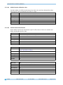
Directory of objects ................................................................................................ 31
5.7.1 Overview of objects ............................................................................................. 31
5.7.2 Description of objects .......................................................................................... 33
5.7.2.1 1000h: Device Type.......................................................................................... 33
5.7.2.2 1001h: Error Register ....................................................................................... 34
5.7.2.3 1002h: Manufacturer Status Register .................................................................. 34
5.7.2.4 1003h: Pre-defined Error Field ........................................................................... 34
5.7.2.5 1005h: COB-ID SYNC message ............................................................................ 35
5.7.2.6 1008h: Manufacturer Device Name ..................................................................... 36
5.7.2.7 1009h: Manufacturer Hardware Version ............................................................... 36
5.7.2.8 100Ah: Manufacturer Software Version ................................................................ 36
5.7.2.9 100Ch: Guard Time........................................................................................... 37
5.7.2.10 100Dh: Life Time Factor.................................................................................... 37
5.7.2.11 1010h: Store Parameter .................................................................................... 37
5.7.2.12 1011h: Restore Parameter ................................................................................. 40
5.7.2.13 1014h: COB-ID Emergency Message .................................................................... 42
5.7.2.14 1017h: Producer Heartbeat Time ........................................................................ 42
5.7.2.15 1018h: Identity Object ..................................................................................... 43
5.7.2.16 1200h: Server SDO Parameter ............................................................................ 44
5.7.2.17 1400h: 1. Receive PDO Parameter ...................................................................... 45
5.7.2.18 1401h: 2. Receive PDO Parameter ...................................................................... 46
5.7.2.19 1600h: 1. Receive PDO Mapping Parameter .......................................................... 47
5.7.2.20 1601h: 2. Receive PDO Mapping Parameter .......................................................... 48
5.7.2.21 1800h: 1. Transmit PDO Parameter ..................................................................... 49
5.7.2.22 1801h: 2. Transmit PDO Parameter ..................................................................... 51
5.7.2.23 1A00h: 1. Transmit PDO Mapping Parameter ........................................................ 52
5.7.2.24 1A01h: 2. Transmit PDO Mapping Parameter ........................................................ 53
AP10
Date: 07.04.2015
Art. No. 86853
Mod. status 132/15
Page 3 of 77
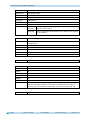
5.7.2.25
5.7.2.26
5.7.2.27
5.7.2.28
5.7.2.29
5.7.2.30
5.7.2.31
5.7.2.32
5.7.2.33
5.7.2.34
5.7.2.35
5.7.2.36
5.7.2.37
5.7.2.38
5.7.2.39
5.7.2.40
5.7.2.41
5.7.2.42
5.7.2.43
5.7.2.44
5.7.2.45
5.7.2.46
5.7.2.47
5.7.2.48
5.7.2.49
5.7.2.50
5.7.2.51
5.7.2.52
5.7.2.53
5.7.2.54
5.7.2.55
5.7.2.56
5.7.2.57
5.7.2.58
5.7.2.59
5.7.2.60
5.7.2.61
5.7.2.62
5.7.2.63
5.7.2.64
5.7.2.65
5.7.2.66
AP10
2001h: Manufacturer Offset ............................................................................... 54
2002h: Calibrate encoder value .......................................................................... 54
2003h: Calibration enable ................................................................................. 55
2004h: Incremental measurement enable ............................................................ 55
2005h: Configuration enable via keyboard and delay of start of configuration .......... 55
5000h: Diagnosis of CAN bus errors .................................................................... 56
5F09h: External Heartbeat timer and external Heartbeat source .............................. 57
5F0Ah: Node-ID, Auto-ID and Baud rate Bus CAN ................................................. 58
5F0Bh: Display in the 2nd row ............................................................................ 59
5F0Ch: Control word ......................................................................................... 59
5F0Dh: Differential value and difference formation ............................................... 60
5F10h: Target window1 (near field) .................................................................... 60
5F11h: Decimal places ...................................................................................... 61
5F12h: Display orientation and LEDs .................................................................. 61
5F13h: Display divisor (ADI) and ADI application ................................................. 64
5F14h: Loop length.......................................................................................... 65
5F15h: Positioning type ................................................................................... 65
5F16h: Read target value .................................................................................. 65
5F17h: Period counter, sensor ADC values and absolute fine value .......................... 67
5F19h: Status word .......................................................................................... 68
5F1Bh: Sensor type and operating mode ............................................................. 68
5F1Ch: Acknowledgement settings ..................................................................... 69
5F1Fh: Direction indicators (CW, CCW) ................................................................ 69
5F21h: Target window2 (far) and target window2 visualization .............................. 69
6000h: Operating Parameters ............................................................................ 70
6001h: Measuring steps per revolution (Display per revolution = APU) .................... 71
6002h: Total of measuring steps ........................................................................ 71
6003h: Preset value (calibration value)............................................................... 71
6004h: Position value ...................................................................................... 72
6200h: Cycle Timer .......................................................................................... 72
6500h: Operating Status ................................................................................... 72
6501h: Single-turn resolution............................................................................ 73
6502h: Number of distinguishable revolutions ..................................................... 73
6503h: Alarms................................................................................................. 73
6504h: Supported Alarms .................................................................................. 74
6505h: Warnings ............................................................................................. 74
6506h: Supported Warnings .............................................................................. 75
6507h: Profile and Software Version ................................................................... 75
6508h: Operating Time ..................................................................................... 75
6509h: Encoder calibration value ....................................................................... 76
650Ah: Module Identification ............................................................................ 76
650Bh: Serial Number....................................................................................... 77
Date: 07.04.2015
Art. No. 86853
Mod. status 132/15
Page 4 of 77
General Information
1
General Information
1.1
Documentation
The following documents describe this product:
The data sheet describes the technical data, the dimensions, the pin assignments, the
accessories and the order key.
The installation instructions describe the mechanical and electrical installation including
all safety-relevant requirements and the associated technical specification.
The user manual for commissioning and integrating the position indicator into a fieldbus
system.
EDS file (electronic data sheet); this file enables integration and configuration in a
CANopen network by means of commercial CANopen configurators.
These documents can also be downloaded at http://www.siko-global.com/p/ap10.
2
Intended use
Absolute position indicator with hollow shaft suitable for direct shaft mounting. Actual and
target values are indicated via the backlit two-row LC display. A direction indicator (arrow) is
blended in if the actual value deviates from the target value including the adjustable target
window. The direction of the arrow indicates the direction of shaft movement necessary to
reach the target. Additionally, various visualization tasks can be realized by means of two bicolor LEDs.
The device parameters can be adjusted by means of 3 keys. You can change the setpoint,
output the position value and adjust all device parameters via the integrated bus interface.
Scanning is magnetically-incremental. In the currentless state, scanning and saving of
changes of the position value are battery-supported.
The state of charge of the replaceable battery is monitored and signified.
Display and interface are active with external power supply only.
2.1
Switching on the supply voltage
The AP10 will be initialized after switching on the supply voltage. A display test is executed
during initialization, the LEDs are lighted consecutively and the configuration parameters are
loaded from the non-volatile memory into the RAM of the controller.
With the display still unconfigured all parameters are set to their default values. See to it that
the bus will be connected only after correct adjustment of baud rate and ID (see chapter 4.3:
Parameterization of the position indicator and chapter 5.6: Auto functions). The AP10
functions with the data last parameterized.
AP10
Date: 07.04.2015
Art. No. 86853
Mod. status 132/15
Page 5 of 77
Display and control keys
After completing the initialization procedure, the AP10 with CAN interface sends a specific
NMT command, the Boot-Up Message, which informs the system about the availability of the
display. The AP10 is now in the Pre-Operational Mode. In this state, the display can be
parameterized via SDO commands in accordance with the requirements of the application. This
applies to configuration parameters as well as to the way it makes available to the system its
position values (asynchronous or synchronous data transmission).
3
Display and control keys
3.1
General
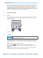
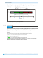
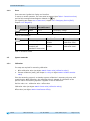
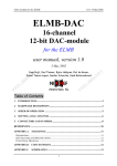
The position indicator has a two-line display with special characters and three control keys.
The keys serve for position indicator parameterization and control. Two LEDs (1) serve for
monitoring positioning.
LED1
Fig. 1: Control elements
3.2
LCD display
The The display range is limited to -19999 … 99999. Values outside this
range are displayed with "".
With supply voltage applied to the position indicator with factory settings, the actual value
will be displayed in the 1st row and the setpoint in the 2nd row. If there is no valid setpoint, "--" will be displayed in the 2nd row. The values displayed are determined by the operating
mode.
Direction indicators (arrows) support positioning.
The battery symbol
is shown with a critical or insufficient battery status.
With incremental measurement function activated, the incremental measurement symbol
is shown.
If battery voltage drops to a critical value, the battery symbol on the display will flash. If it
falls below the minimum value, the symbol will glow permanently.
AP10
Date: 07.04.2015
Art. No. 86853
Mod. status 132/15
Page 6 of 77
Functional Description
3.2.1
Extended display range
Values up to -999999 can be displayed by means of the control word. If the relevant bit has
been set and the value to be displayed is between -199999 and -999999, then the negative
sign and the digit of the highest order will flash alternately. If the value range drops below 99999, "" will be displayed.
3.3
LED display
In its basic state (factory setting) the LED display has different meanings depending on the
operating mode (see chapter 4.1.1: Position-bound operating modes and 4.1.2: Alpha-numeric
display operating mode).
With the basic function of the LEDs inactivated, every LED can be controlled independently via
the control word (see object 5F12h: Display orientation and LEDs and chapter 5.3.2: Control
word).
3.4
Keys
Pressing the
key enables or disables the incremental measurement function. With the
Auto-ID function, the new ID is adopted by actuating this key (see chapter 5.6: Auto
functions).
Pressing the
key starts calibration (see chapter 4.5.1: Calibration) and acknowledges a
pending error (see chapter 4.4.2: Errors).
Pressing the
key starts the parameterization mode (see chapter 4.3: Parameterization of
the position indicator).
4
Functional Description
4.1
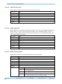
Operating modes
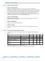
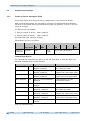
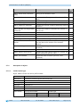
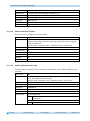
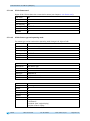
The following position-dependent operating modes are differentiated: Absolute Position,
Differential Value, Modulo and the position-independent operating mode Alpha-numeric
Display.
Operating
mode
Line 1
Line 2
Absolute position
Differential value Modulo
Actual position
Set point
Actual position
Differential value
Actual position
Set point
Alpha-numeric
Display
Set point1
Set point2
Table 1: Display with different operating modes
Absolute position:
Linear absolute position values are displayed.
AP10
Date: 07.04.2015
Art. No. 86853
Mod. status 132/15
Page 7 of 77
Functional Description
Differential value display:
With factory setting: Differential value = actual position - set point
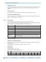
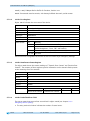
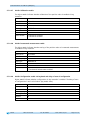
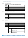
Modulo display:
Position values ranging from 0° to 360° are displayed.
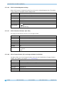
Using the "Decimal places" parameter (see object 5F11h: Decimal places) the resolution and
the modulo point of the displayed values are set.
Decimal places
0
1
2
3
4
Display resolution
1°
1/10°
1/100°
1/1000°
1/10000°
Value range
0°…360°
0.0°…360.0°
0.00°…360.00°
0.000°…360.000°
0.0000°…360.0000°
Table 2: Modulo display
Alpha-numeric display:
Both rows can be written freely. Setpoint1 is received via the Receive data object 1 (RPDO1),
setpoint2 is received correspondingly with RPDO2. The data identifier must be correctly set in
the relevant control word. The data identifier differentiates whether the data is interpreted
and displayed as figures or alpha-numeric characters (ASCII) (see chapter 5.3.2: Control
word).
4.1.1
Position-bound operating modes
4.1.1.1
Positioning
(see chapter 4.1.1.2: Loop positioning)
Arrows: (see object 5F1Fh: Direction indicators (CW, CCW))
Arrows are displayed to support the user with positioning as long as the current actual
position value is outside (see object 5F10h: Target window1 (near field)) target window1. The
direction of the arrow indicates the direction of shaft rotation in order to arrive at the
setpoint.
LED display: (see e. g. object 5F12h: Display orientation and LEDs)
With factory setting, the LED glows green as long as the actual position is within the
programmed window1. When leaving target window1, the LED glows red. The shaft must be
rotated in the direction of the glowing LED in order to arrive at the setpoint. The red glowing
LED on the right means: clockwise (cw) rotation required. Red glowing LED on the left:
counter-clockwise (ccw) rotation required.
An additional target window (target window2) and an associated visualization can also be
configured (5F21h: Target window2 (far) and target window2 visualization).
AP10
Date: 07.04.2015
Art. No. 86853
Mod. status 132/15
Page 8 of 77
Functional Description
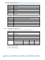
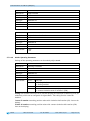
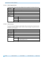
With factory settings, the LED display has the following meaning:
Operating state
There is no valid
setpoint.
There is a valid
setpoint.
LED
both
Status
off
Meaning
Positioning disabled.
LED left
off
Target window not reached!
The shaft must be rotated clockwise (cw) in
order to reach the target.
Target window not reached!
The shaft must be rotated counter-clockwise
(ccw) in order to reach the target.
Target window reached
Target window not reached!
The shaft must be rotated counter-clockwise
(ccw) in order to reach the target.
Target window not reached!
The shaft must be rotated clockwise (cw) in
order to reach the target.
Target window reached
red
green
off
LED right
red
green
Table 3: LED display
Control word (see chapter 5.3.2: Control word):
The setpoint is not displayed and positioning not monitored unless the setpoint is marked as
valid in the control word.
Status word (see chapter 5.3.3: Status word):
Upon reaching target window1, the static and dynamic target-window-reached bits are set in
the status word. The dynamic bit is deleted when leaving target window1. The user must
acknowledge the static bit.
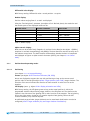
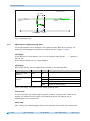
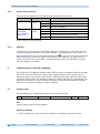
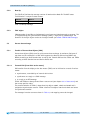
Example Position monitoring:
Parameterization:
Factory setting
Additionally:
Set point
= 100
Positioning monitoring
LED left
LED right
95
-
105
+
100
Target
window1
Fig. 2: Positioning monitoring
AP10
Date: 07.04.2015
Art. No. 86853
Mod. status 132/15
Page 9 of 77
Functional Description
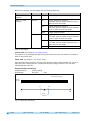
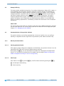
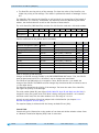
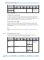
Example of position monitoring with additionally activated target window2 parameter:
Parameterization:
Factory setting
Additionally:
Target window 2
= 15
Visualization target window 2 = 1
Set point
= 100
Positioning monitoring
LED left
LED right
Target window2
95
-
105
100
85
115
Target
window1
+
Fig. 3: Positioning monitoring with target window2
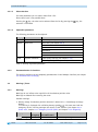
4.1.1.2
Loop positioning
Target window1 is also applied to the loop length.
If the position indicator is operated on a spindle or an additional gear, the spindle or external
gear backlash can be compensated by means of loop positioning. Therefore, movement
towards the setpoint is always in the same direction. This direction of approach can be
defined.
Example:
The direction from which every target position shall be driven to is positive.
Case 1 the new position is greater than actual position:
Direct travel to the target position.
Case 2 the new position is smaller than actual position:
The position indicator's arrows show that the set point is to be overrun by the loop length.
Afterwards, the set point is approached in positive direction.
AP10
Date: 07.04.2015
Art. No. 86853
Mod. status 132/15
Page 10 of 77
Functional Description
Positioning: loop +
Loop length
Positioning in positive
direction
-
Positioning in negative
direction
Target window1
+
Set point
Fig. 4: Positioning Loop+
4.1.2
Alpha-numeric display operating mode
Two 6-digit setpoints can be displayed in this operating mode. With factory settings, the
setpoints are acknowledged by pressing the asterisk key (see chapter 3.4: Keys).
LCD display:
In the absence of a valid setpoint, the 1st row is displayed empty (blank). " --- " appears in
the 2nd row.
A valid setpoint flashes until it is acknowledged.
LED display:
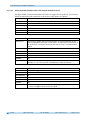
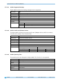
With factory settings, the LED display works according to the following table.
Operating state
There is no valid
setpoint.
There is a valid
setpoint.
LED
both
Status
off
Meaning
LED left
red
green
red
green
Setpoint1 not acknowledged
Setpoint1 acknowledged
Setpoint2 not acknowledged
Setpoint2 acknowledged
LED right
Table 4: LED display in the alpha-numeric display operating mode
Control word:
In the control word, the relevant type (number or character string) and the validity of the
setpoint is transmitted to the display. As an additional option, the setpoint can be
acknowledged via the control word.
Status word:
Type, validity and acknowledgement status of the setpoints are fed back in the status word.
AP10
Date: 07.04.2015
Art. No. 86853
Mod. status 132/15
Page 11 of 77
Functional Description
4.2
Battery buffering
The battery makes possible the detection of currentless displacement. Battery life is approx. 5
years depending on the duration of battery operation (including storage) and frequency of
currentless adjustments. Battery voltage is checked at intervals of approx. 5 min. If battery
voltage drops below a specified value, the battery symbol
will blink on the display. If
the battery voltage continues to drop,
will be displayed permanently. The battery
should be replaced within approx. three months after the first appearance of the battery
symbol. The battery can be replaced by the SIKO distribution partners or at the SIKO main
factory. For battery replacement it is mandatory to follow the instructions of the installation
instructions.
Status word:
The charge status of the battery is signified in the status word. CANopen Emergency messages
are sent upon detection of a critical charge state and with detection of the empty state (see
chapter 5.5.1: Emergency Service (EMCY)).
4.3
Parameterization of the position indicator
The position indicator can be fully parameterized via the bus interface. You can configure
manually via keyboard the most significant bus parameters (node address and baud rate).
4.3.1
Manual parameterization
4.3.1.1
Starting parameterization
After applying supply voltage and completion of initialization, the position indicator is on the
uppermost level of the menu structure (default/Factory settings).
By actuating the
key, the set node address and baud rate is displayed. Parameterization
starts if it is actuated for the duration of the enable time (see object 2005h: Configuration
enable via keyboard and delay of start of configuration).
4.3.1.2
Value input
Enter values via the
key and the
key. Confirm values entered by pressing the
key.
- decimal place selection key
- value input key
AP10
Date: 07.04.2015
Art. No. 86853
Mod. status 132/15
Page 12 of 77
Functional Description
4.3.1.3
Value selection
For some parameters you can select values from a list.
Direct value input is not possible there.
Pressing the
key, the value can be selected from the list. By pressing the
selection is confirmed.
4.3.1.4
key, the
Adjustable parameters
The following parameters can be adjusted.
Display
ID
KBAUD
Parameter
Node-ID
Baud rate
CODE
System commands
Options
1 … 127 (see chapter 5.6.2)
Auto baud (see chapter 5.6.1)
125 kbaud
250 kbaud
500 kbaud
800 kbaud
1000 kbaud
Load factory settings (see chapter 4.5.2)
Start diagnosis (see chapter 4.5.3)
Table 5: Manually adjustable parameters
4.3.2
Parameterization via interface
The position indicator can be completely parameterized in the CANopen interface (see chapter
5.4: Parameter data exchange).
4.4
Warnings / Errors
4.4.1
Warnings
Warnings do not influence the acquisition of the absolute position value.
Warnings are deleted after removing the cause.
Possible warnings:
Battery voltage for absolute position detection is below limit immediately exchange
battery!
This warning is displayed with a blinking battery symbol
. Via status word and the
emergency service, warning messages are output via the interface (see chapter 5.3.3:
Status word, chapter 5.5.1: Emergency Service (EMCY) and chapter 4.5.3: Diagnosis).
Display
blinking
AP10
Error code
Emergency
3200h
Date: 07.04.2015
Bit assignment in
the status word
11
Art. No. 86853
Error
Low battery voltage
Mod. status 132/15
Page 13 of 77
Functional Description
4.4.2
Errors
Error states are signalled via display and interface.
To return to normal operation, the cause must be removed (see Table 7: Corrective actions)
and the fault message acknowledged or deleted via
key.
(For signaling see chapter 5.3.3: Status word, chapter 5.5.1: Emergency Service (EMCY)
chapter 4.5.3: Diagnosis)
Display
permanent
SPEED
Error code
Emergency
3200h
FF12h
Bit assignment in
the status word
11+7
12
Error
Low battery voltage
Admissible speed exceeded
Table 6: Error messages
Display
permanent
Error
Battery empty
SPEED
Admissible speed
exceeded (see
installation instruction)
Possible effect
Position value not
reliable
Position value not
reliable
Corrective actions
Battery change +
calibration travel
Reduce speed +
calibration travel
Table 7: Corrective actions
4.5
System commands
4.5.1
Calibration
Two steps are required for executing calibration:
1.
Write calibration value (see object 6003h: Preset value (calibration value))
2.
Execute calibration (reset) (see chapter 3.4: Keys or object 2002h: Calibrate encoder
value)
Since the measuring system is an absolute system, calibration is necessary only once with
commissioning. With calibration, the calibration value is adopted for calculation of the
position value. The following equation is applied in case of calibration:
Position value = 0 + calibration value + offset value
Calibration value (see object 6003h: Preset value (calibration value))
Offset value (see object 2001h: Manufacturer Offset)
AP10
Date: 07.04.2015
Art. No. 86853
Mod. status 132/15
Page 14 of 77
Communication via CAN bus (CANopen)
4.5.2
Restore factory settings
There are various options for restoring the factory settings of the device:
Access
Manual
Coding
CANopen
(see object
1011h: Restore
Parameter)
1011h
"load"
Factory settings are restored
all parameters
all except bus parameters
only bus parameters
all parameters
only bus parameters
only Draft-Standard-406 parameters
only manufacturer-specific parameters
011100
011102
011105
Subindex 1
Subindex 2
Subindex 3
Subindex 4
Table 8: Access to factory settings
4.5.3
Diagnosis
To receive a list of all errors occurring from chapter 4.4.2 of the device, the device must be
switched to diagnosis operation. Enter CODE "200000" in parameterization (see chapter 4.3.1:
Manual parameterization) and confirm by pressing the
key. Any errors occurring are output
indicating the error number and total of occurrences in the upper row. The type of error is
shown in the lower row. Error number 1 contains the latest error. The oldest error is output
with the highest error number.
5
Communication via CAN bus (CANopen)
The CiA DS-301 V4.2 CANopen communication profile as well as the Device profile for Encoders
CiA DS-406 V3.2 form the basis for AP10, which supports device class C2. As this device is
beyond the scope of an encoder's functionality, communication partly differs from the abovementioned device profile. This document contains the details necessary for understanding the
operation of the device. If more-in-depth information is required we recommend to consult
the pertinent specialized literature on CAN or CANopen.
5.1
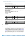
Telegram setup
The data telegram of a CAN message consists of the following fields:
SOF
Identifier (COB-ID)
Control field
Data field (max. 8 byte)
CRC
ACK / EOF
SOF:
(Start of Frame) start bit of the telegram
Identifier (COB-ID):
All bus sharing units check via identifier whether the message is relevant for them.
AP10
Date: 07.04.2015
Art. No. 86853
Mod. status 132/15
Page 15 of 77
Communication via CAN bus (CANopen)
The identifier sets the priority of the message. The lower the value of the identifier, the
higher the priority of the message. This results in preferential transfer of messages via the
bus.
The Identifier field contains the identifier as well as bits for the recognition of the length of
the identifierss (11 or 29 bit). Furthermore, the identifier serves for determining the device
address, the channel selection as well as the direction of data transfer.
The 11bit identifier (COB identifier) consists of a 4bit function code and a 7bit node number:
Bit no.
Type
Assignment
10
9
8
Function code
x
x
x
7
x
6
5
4
3
Node number (node ID)
0
0
x
x
2
1
0
x
x
x
The following function codes have been defined in the "Pre-defined Connection Set" (only the
function codes used in the present device are listed):
Object
Network management (NMT)
SYNC message
Emergency message
TPD01
RPD01
TPD02
RPD02
SDO (tx)
SDO (rx)
Heartbeat message
Node Guard message
Function code
0000b
0001b
0001b
0011b
0100b
0101b
0110b
1011b
1100b
1110b
1110b
Resulting COB-ID
0
128 (80h)
128 (80h) + Node-ID
384 (180h) + Node-ID
512 (200h) + Node-ID
640 (280h) + Node-ID
768 (300h) + Node-ID
1408 (580h) + Node-ID
1536 (600h) + Node-ID
1792 (700h) + Node-ID
1792 (700h) + Node-ID
Object
1005h
1014h
1800h
1400h
1801h
1401h
1200h
1200h
-
Page
17
35
42
49
45
51
46
44
44
27
26
Table 9: Overview of COB identifiers
Changes to COB-IDs are only possible in the PRE-OPERATIONAL NMT status. First, the COB-ID
must be deactivated via Bit 31 = 1b before it can be changed and reactivated.
The COB-ID of the SYNC object is an exception. There, Bit 30 must be = 0 to enable the
change of the COB-ID. The COB-ID could be changed any time because Bit 30 cannot be set to
1 in the AP10 device.
The identifier determines the priority of the message. The lower the value of the identifier,
the higher the priority of the message.
The node number (Node-ID) (see object 5F0Ah: Node-ID, Auto-ID and Baud rate Bus CAN) is
assigned in every bus system once while AP10 is being configured. Node-ID = 0 is reserved
and must not be used; thus the node numbers are in the range of 1 to 127.
A newly set node number will only be adopted with reinitialization (see chapter 5.2.1:
Network management services (NMT)).
The setpoint display is delivered with the factory-set Node-ID 125 (7Dh).
Control field:
Contains bit-by-bit information on the number of user data and decides whether a data frame
or a Remote Transmission Request (RTR) frame is concerned.
AP10
Date: 07.04.2015
Art. No. 86853
Mod. status 132/15
Page 16 of 77
Communication via CAN bus (CANopen)
Data field:
Contains up to 8 bytes of user data. The user data has a different meaning depending on the
channel selection.
CRC:
Contains bits for error detection.
ACK/EOF:
The ACK/EOF field contains telegram acknowledgement bits as well as bits for determining the
end of telegram.
For a detailed description of the telegram refer to the relevant CAN expert literature. For
simplification, only identifier (COB-ID) and data field will be dealt with in the subsequent
telegram descriptions.
5.2
Node control
5.2.1
Network management services (NMT)
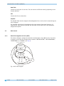
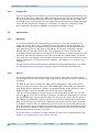
The master configures, manages and monitors network nodes via the NMT service. The device
is always in one of the four communication statuses "INITIALISATION", "PRE-OPERATIONAL",
"OPERATIONAL" or "STOPPED" (see Fig. 5).
Power on or software reset
Re-initialization
CAN-card
5
Init
Initialization
CAN-communication
5
5
4
BootUp Message
4
3
4
2
3
1
1
2
Fig. 5: NMT status diagram
AP10
Date: 07.04.2015
Art. No. 86853
Mod. status 132/15
Page 17 of 77
Communication via CAN bus (CANopen)
5.2.1.1
NMT communication statuses
NMT Status INITIALIZATION
The unit is not involved in the bus actions in this state. All hardware and software
components are initialised. This state is attained after switching on the device or after receipt
of the command code 81h of the own or global addresses. After receiving the command code
82h, the display is also in the initialization status. However, only the hardware and software
associated with CAN communication is reinitialized. The device automatically signifies
completion of initialization via a boot-up message. After successful transmission of the bootup message, the device will be in the "PRE-OPERATIONAL" status.
NMT Status PRE-OPERATIONAL
Parameterization data (SDO) can be exchanged in the Pre-Operational Mode. However, no
process data (PDO) is transferred.
NMT Status OPERATIONAL
Exchange of process data is enabled as well.
NMT Status STOPPED
Communication is stopped except for Heartbeat and Node Guarding . Only NMT communication is
enabled.
5.2.1.2
Switching between NMT communication states
Telegrams with the following structures are used for switching between the communication
statuses:
Status change
from
PRE-OPERATIONAL / STOPPED
OPERATIONAL/ PRE-OPERATIONAL
OPERATIONAL / STOPPED
OPERATIONAL / PRE-OPERATIONAL /
STOPPED
OPERATIONAL / PRE-OPERATIONAL /
STOPPED
to
OPERATIONAL
STOPPED
PRE-OPERATIONAL
INITIALISATION
(Reset Node)
INITIALISATION
(Reset Communication)
Transition COB-ID Com.
in Fig. 5
NodeID
1
2
3
5
0h
0h
0h
0h
01h
02h
80h
81h
x
x
x
x
4
0h
82h
x
Table 10: Switching between communication statuses
If transmitted as Node-ID x = 0, the message is intended for all bus subscribers.
AP10
Date: 07.04.2015
Art. No. 86853
Mod. status 132/15
Page 18 of 77
Communication via CAN bus (CANopen)
5.2.2
Boot-Up
The COB-ID of the Boot-Up message consists of 700h and the Node-ID. The NMT-status
"Initialization" is output as data content.
COB-ID
700h + Node-ID
Byte 0
00h
Table 11: Boot-up message
5.2.3
SYNC object
CANopen makes it possible to simultaneously scan inputs and simultaneously set outputs. This
is accomplished by the synchronization message (SYNC), a high-priority CAN message. The
identifier of the Sync object can be set via object 1005h (see 1005h: COB-ID SYNC message).
5.3
Process data exchange
5.3.1
Transfer of Process Data Objects (PDO)
Process data objects (PDO) serve for quick process data exchange. A maximum of 8 bytes of
user data can be transferred in a PDO. AP10 supports the Receive-PDO services RPDO1 and
RPDO2 according to Draft Standard 301 as well as the Transmit-PDO services TPDO1 and TPDO2
according to Draft Standard 301 and Device Profile 406.
5.3.1.1
Transmit PDO (from AP10 to the master)
PDO transfer from the display to the bus master (TPDO) can be initiated as a result of various
events:
asynchronous, controlled by an internal device timer
synchronous as a reply to a SYNC message
as a reply to an RTR message
TPDO1 and TPDO2 are always formed from a status word (see chapter 5.3.3: Status word) and
the current position value.
The transfer behavior of TPDO1 is determined via objects 1800h, 1A00h and 6200h and is
assigned to asynchronous transfer. TPDO2 is defined via objects 1801h and 1A01h and serves
for synchronous transfer.
The messages have the structure shown in Table 12, and mapping cannot be changed
AP10
Date: 07.04.2015
Art. No. 86853
Mod. status 132/15
Page 19 of 77
Communication via CAN bus (CANopen)
COB-ID
Process data in binary code
TPDO1
180h + Node-ID
TPDO2
280h + Node-ID
Byte 0 Byte 1
(LSB)
Position value
Byte 2
Byte 3
(MSB)
Byte 4
Byte 5
Dummy 0x0000
Byte 6
Byte 7
5F19h: Status
word (see
chapter 5.3.3)
Table 12: TPDO message
Asynchronous data transfer (TPDO1)
If a TPDO1 is to be sent cyclically, then the cycle time must be entered into object 1800h,
sub-index 5, in milliseconds. The TPDO1 will not be sent if the value 0 ms is written. The
function is disabled. The minimum value to be set is 1 (=1 ms). Alternately, the value can also
be written into the object 6200h which is permanently linked internally.
Synchronous data transfer (TPDO2)
The device is factory set to reply by output of the TPD02 message when receiving a SYNC
message. Thus it is set to the synchronous transfer type. 1 is entered in object 1801h, subindex 2. The device responds to every n SYNC message if a value n between 1 and 240 (=F0h)
has been entered.
RTR
Queries can be sent to TPD01 and TPD02 via RTR (see chapter 5.1: Telegram setup, Control
field).
5.3.1.2
Receive-PDO (from master to AP10)
Using Receive-PDO transfer (RPDO), setpoints and control commands (see chapter 5.3.2:
Control word) can be transmitted from the bus master to the display.
COB-ID
Process data in binary code
RPDO1
200h + Node-ID
RPDO2
300h + Node-ID
Byte 0 Byte 1
(LSB)
Target value 1
Byte 2
Byte 3
(MSB)
Byte 4
Byte 5
Byte 6
Byte 7
Data identifier
5F0Ch: Control
equal to ASCII:
word (see
Byte 4 and 5 of chapter 5.3.2)
setpoint 1
Otherwise dummy
0x0000
Data identifier
equal to ASCII:
Byte 4 and 5 of
setpoint 2
Otherwise dummy
0x0000
Target value 2
Table 13: RPDO message
AP10
Date: 07.04.2015
Art. No. 86853
Mod. status 132/15
Page 20 of 77
Communication via CAN bus (CANopen)
The transfer behavior of RPDO1 is defined via objects 1400h and 1600h. RPDO2 is defined via
objects 1401h and 1601h.
A differentiation is made between Setpoint1 und Setpoint2 only in the alpha-numeric display
mode. Setpoint1 is displayed in the upper row and Setpoint2 in the lower row. In the
position-dependent modes, the setpoint last received, if valid, is output in the 2nd row.
5.3.2
Control word
The control word consists of 16 bits and is mapped in the object 5F0Ch: Control word. This
object is received with both Receive PDOs.
Control word
15 14 13 12 11
MSB
High Byte
10
9
8
7
6
5
4
Low Byte
3
2
1
0
LSB
The following table lists the designations of the individual bits of the control word and their
meanings.
Bit
0
1
2
3
4
5
6
7
8
9
10
11
12
13
14
15
Meaning
reserved
reserved
Validity of setpoint1
Display range
Acknowledgment target window1 static
reserved
With "Display" operating mode:
Acknowledgement of setpoint2
With "Display" operating mode:
Data identifier
Guarding Bit
Validity of setpoint2
With "Display" operating mode:
Acknowledgement of setpoint1
LED1 green left
LED3 green right
LED4 red right
LED2 red left
LED blinking
Value = 0
ever 0
ever 0
invalid
standard
not acknowledged
ever 0
not acknowledged
Value = 1
valid
extended
acknowledged
acknowledged
number
ASCII
is taken over
invalid
not acknowledged
is taken over
valid
acknowledged
Off
Off
Off
Off
Off
On
On
On
On
On
Table 14: Control word
AP10
Date: 07.04.2015
Art. No. 86853
Mod. status 132/15
Page 21 of 77
Communication via CAN bus (CANopen)
5.3.3
Status word
The status word indicates the current status of AP10. It consists of 16 bits and is mapped in
the object 5F19h: Status word as well as in the two Transmit-PDOs.
Status word
15 14 13 12 11
MSB
High Byte
10
9
8
7
6
5
4
Low Byte
3
2
1
0
LSB
The following table lists the designations of the individual bits of the status word and their
meanings.
Bit
0
1
2
3
4
5
6
7
8
9
10
11
12
Meaning
Direction indication CW
Direction indication CCW
Validity setpoint1
Target window2 dynamic
With "Display" operating mode:
Acknowledgement of setpoint2
Target window1 static
Target window1 dynamic
With "Display" operating mode:
Acknowledgement of setpoint1
Deviation
Battery empty (fault)
Guarding Bit
Position value = incremental measurement
With "Display" operating mode:
Data identifier
Validity setpoint2
Battery status (warning)
Sensor error
(Tape-Sensor or Lost-Sensor or Speed)
Value = 0
OFF
OFF
invalid
not reached
not acknowledged
Value = 1
ON
ON
valid
reached
acknowledged
never reached
not reached
not acknowledged
reached
reached
acknowledged
actual position <=
set point
not present
is output
OFF
number
actual position >
set point
is present
is output
ON
ASCII-String
invalid
all right
not present
valid
critical
is present
13
key
not actuated
actuated
14
key
not actuated
actuated
15
key
not actuated
actuated
Table 15: Status word
AP10
Date: 07.04.2015
Art. No. 86853
Mod. status 132/15
Page 22 of 77
Communication via CAN bus (CANopen)
5.4
Parameter data exchange
5.4.1
Transfer of Service data objects (SDO)
Service data objects serve mainly for device configuration via the directory of objects.
SDOs are exchanged between two participants exclusively via expedited Request/Response.
User data is sent already with the initialization message. The identifier is set to 11 bits and
cannot be changed.
Two SDO services are available:
SDO (rx) (master AP10):
600h + Node-ID
SDO (tx) (AP10 master):
580h + Node-ID
These SDO identifiers cannot be changed!
SDO messages are set up as follows:
COB-ID
SDO rx/tx
+ Node-ID
User data in binary code
Byte 0
Byte 1
read / write LSB
command
index
Byte 2
MSB
Byte 3
subindex
Byte 4 Byte 5 Byte 6
LSB
service data (parameters)
Byte 7
MSB
Command byte, Byte 0:
The command byte determines the type of access and the number of valid data bytes. The
following command bytes are valid for AP10:
Command byte
Write Request
23h
Write Request
2Bh
Write Request
2Fh
Write Response
60h
Read Request
40h
Read Response
43h
Read Response
4Bh
Read Response
4Fh
Error Response
80h
Type
SDO (rx), Initiate Download
Request, expedited
SDO (rx), Initiate Download
Request, expedited
SDO (rx), Initiate Download
Request, expedited
SDO (tx), Initiate Download
Response
SDO (rx), Initiate Upload
Request
SDO (tx), Initiate Upload
Response, expedited
SDO (tx), Initiate Upload
Response, expedited
SDO (tx), Initiate Upload
Response, expedited
SDO (tx), Abort Domain
Transfer
Function
Send parameter to AP10
(all 4 data bytes valid)
Send parameter to AP10
(2 bytes from 4 data bytes valid)
Send parameter to AP10
(1 byte from 4 data bytes valid)
Acknowledgement of data
acquisition to master
Request parameter from AP10
Report parameter to master
(all 4 data bytes valid)
Report parameter to master
(2 bytes from 4 data bytes valid)
Report parameter to master
(1 byte from 4 data bytes valid)
AP10 reports error code to master
Table 16: Command coding
AP10
Date: 07.04.2015
Art. No. 86853
Mod. status 132/15
Page 23 of 77
Communication via CAN bus (CANopen)
Index, bytes 1 and 2:
The index (object number) is entered in user data byte 2 (low byte) and in in user data byte 3
(high byte) in the Intel data format. Here, the index of the object to be parameterized is
entered.
Sub-index, byte 3:
The sub-index indicates the number of the fields for objects realized as an array.
Service data (Parameter), byte 4-7:
In the service data area, the value of the parameter is entered in left-aligned Intel notation.
Byte 4 = low-Byte ... Byte 7 = high Byte
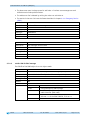
5.4.1.1
Error Response
An error report (Abort) is returned to the master in case of invalid access.
The error codes are described in the CANopen profile (DS 301) or in the encoder profile (DSP
406), respectively. The following table shows the error codes used:
Error code
06010000h
06010001h
06010002h
06020000h
06090011h
06090030h
08000020h
08000022h
Description
Wrong access to an object.
Read access to Write-Only.
Write access to Read-Only.
Object doesn't exist in the object directory.
Sub-index does not exist.
Wrong value range of selected parameter.
Parameters cannot be transferred to application or stored.
Parameters cannot be transferred to application or stored due to the
current device status.
No data available
08000024h
Table 17: Error code
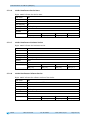
Example of reading SDO parameters:
Read the calibration value stored in object 6003h of the directory of objects from AP10 with
device address 1.
Calculation of the identifier: 600h + Node-ID = 600h +1h = 601h
Command: 40h
Index: 6003h
Sub-index: 00h
The current value is 510 = 01FEh
Query by master from slave with Node-ID 1:
COB-ID User data
601h
AP10
Command
40h
Index L
03h
Date: 07.04.2015
Index H
60h
Sub-index Data 0 Data 1 Data 2 Data 3
00h
x
x
x
x
Art. No. 86853
Mod. status 132/15
Page 24 of 77
Communication via CAN bus (CANopen)
Response to the request by the slave:
Calculation of the identifier: 580h + Node-ID = 581h
COB-ID
User data
581h
Command
43h
(4 bytes
valid)
Index LB
03h
Index HB Sub-index Data 0 Data 1 Data 2 Data 3
60h
00h
FEh
01h
00h
00h
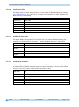
Example of writing SDO parameters:
Change the loop length stored with 2 bytes in object 5F14h of the directory of objects in the
AP10 with device address 1.
Calculation of the identifier: 600h + Node-ID = 600h + 1 = 601h
Command: Write 2 bytes: 2Bh
Index: 5F14h
Sub-index: 00h
The new value shall be 4500 = 1194h
Example of writing SDO parameters:
COB-ID User data
601h
Command
2Bh
(2 bytes
valid)
Index L
14h
Index H
5Fh
Sub-index Data 0 Data 1 Data 2 Data 3
00h
94h
11h
00h
00h
Response by slave to the command:
Calculation of the identifier: 580h + Node-ID = 580h + 1 = 581h
COB-ID User data
581h
Command
60h
Index L
14h
5.5
Node monitoring
5.5.1
Emergency Service (EMCY)
Index H
5Fh
Sub-index Data 0 Data 1 Data 2 Data 3
00h
00h
00h
00h
00h
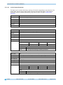
The status of the bus subscriber is transferred via high-priority emergency messages in case of
error. These messages have a data length of 8 bytes and contain information on the error.
The emergency message is transferred as soon as a serious communication error occurred or
was corrected. The cause of error is stored in the error buffer (see object 1003h: Pre-defined
Error Field). An emergency object is sent only once per error event. Removal of a cause of
error is signified by sending an emergency message with Error Code 0000h (No Error). If
multiple errors exist and one cause of an error has been corrected, then Error Code 0000h is
output as well; however, the persisting error condition is indicated in the Error Register.
AP10
Date: 07.04.2015
Art. No. 86853
Mod. status 132/15
Page 25 of 77
Communication via CAN bus (CANopen)
Identifier
11/ 29 Bit
Byte 0 Byte 1
Emergency Error
Code
Byte 2
Byte 3 Byte 4 Byte 5 Byte 6 Byte 7
Error Register
Manufacturer-specific error field
(Object 1001h) (not used)
Emergency Error Code:
Error description
Cause of error removed
Battery empty
Bus status changed to Error Passive Mode
Recovered from Bus Off
Manufacturer-specific: Speed error
Manufacturer-specific: critical battery status
Error Code
0x0000
0x3200
0x8120
0x8140
0xFF12
0xFF20
Table 18: Emergency Error Code
The identifier of the emergency object is set to 80h + Node-ID by default; however, it can be
changed via object 1014 h (see 1014h: COB-ID Emergency Message). Transmission of an
emergency message is only possible in the "OPERATIONAL" or "PRE-OPERATIONAL" NMT
statuses.
5.5.2
Node Guarding
Node Guarding is available for failure monitoring of the CANopen network. During guarding,
the master transmits remote frames (RTR, remote transmit request, request message) on the
guarding identifiers of the nodes to be monitored. They respond with the Guarding message,
which contains the current NMT status of the node as well as a toggle bit whose value must
change with every message. If NMT status or toggle bit do not correspond with the value
expected by the master or if there is no response, then the master assumes a node error.
Via objects 100Ch (Guard Time) 100Dh (Life Time Factor), the time interval (Life-Time) is set
within which the NMT master expects to receive a message. The time interval "Life time" is
calculated from the cycle time "Guard time" multiplied with the factor "Life Time Factor". If
the NMT master receives no response to its RTR frame within the "Life-Time", it can react with
appropriate measures. After switching on, Node Guarding is activating by the master sending
the first RTR frame to the slave. If the value of either object (100Ch or 100Dh) is set to 0,
Node Guarding will be deactivated.
The node's response to the master's RTR frame is formed as follows:
Identifier
700h + Node-ID
Byte 0
Bit 7: toggle Bit
Bit 6 … 0: NMT status
Toggle Bit:
The toggle bit must alternate between two subsequent responses of the unit. After activation
of the Guarding protocol, the toggle bit must have the value 0 with the first response.
AP10
Date: 07.04.2015
Art. No. 86853
Mod. status 132/15
Page 26 of 77
Communication via CAN bus (CANopen)
NMT status:
4: STOPPED
5: OPERATIONAL
127: PRE-OPERATIONAL
The identifier of the heartbeat protocol is permanently set to 700h + Node-ID and cannot be
changed. Sending of a Node Guard message is possible in the "OPERATIONAL",
"PREOPERATIONAL" or "STOPPED" NMT statuses.
5.5.3
Heartbeat
The master monitors the status of the slave device via the Heartbeat protocol. While doing
this, the unit sends cyclically its NMT status. The AP10 is a heartbeat producer, it does not
receive nor process heartbeat protocols. The cycle time of the heartbeat message is set via
object 1017h. The heartbeat protocol is inactivated if the cycle time is 0.
The heartbeat message consists of the COB-ID and an additional byte, which is used to store
the current NMT status.
COB-ID
700h + Node-ID
Byte 0
NMT status
NMT status:
4: STOPPED
5: OPERATIONAL
127: PRE-OPERATIONAL
The identifier of the heartbeat protocol is permanently set to 700h + Node-ID and cannot be
changed. Sending of a Node Guard message is possible in the "OPERATIONAL",
"PREOPERATIONAL" or "STOPPED" NMT statuses.
5.5.4
External heartbeat
In addition to the function described under Heartbeat, the NMT status can be controlled via
the external heartbeat. In this case, a value corresponding to an interval in ms is entered in
object 5F09h sub-index 1. If the devices receives no external heartbeat message during this
interval, the display will switch over to Pre-Operational status. The type of message to be
interpreted as external heartbeat is set in object 5F09h sub-index 2. The value 0 means that
the timer is triggered when receiving an RPDO (setpoint). With value 1, the timer is triggered
when receiving a SYNC (see object 5F09h: External Heartbeat timer and external Heartbeat
source).
AP10
Date: 07.04.2015
Art. No. 86853
Mod. status 132/15
Page 27 of 77
Communication via CAN bus (CANopen)
5.5.5
Guarding Bit
There is a guarding bit in the control word, which serves for monitoring communication or the
NMT state of the device, respectively. When receiving the control word, the content of this bit
will be copied into the guarding bit of the status word and output with the next TPDO. Thus,
by shifting the bit in the control word, the superordinate control can verify without additional
data traffic that process data exchange is in operation. This function is especially helpful
when a gateway (converter from CANOpen to superordinate fieldbus) is used.
5.6
Auto functions
5.6.1
Auto-Baud
This function facilitates first commissioning of the devices in the plant. The baud rate is
factory-set to "Auto Baud". AP10 "overhears" the bus and does not transmit messages. To
enable the instrument's autonomous recognition and adjustment of the prevalent bus baud
rate, communication must take place on the CAN bus. If the device recognizes a faultless
message with the internally set baud rate it will be adopted as a valid baud rate, CAN
initialization finished and a boot-up message sent. If no message is detected till expiry of the
dwell time, then the next valid baud rate is set and checked for communication. The search
for a baud rate is not stopped until a valid baud rate has been found. If the baud rate is to be
adopted permanently, it must be saved upon command. (see chapter 5.7.2.11: 1010h: Store
Parameter).
The Auto Baud function can be activated or deactivated during parameterization (see chapter
4.3: Parameterization of the position indicator) and the desired baud rate directly set.
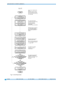
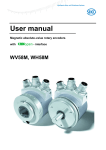
5.6.2
Auto-ID
This function facilitates first commissioning of the devices in the plant. The node numbers
can be assigned by the superordinate control or by pressing the relevant button on the device
concerned.
The Node ID 7Dh (125d) is factory-set. After finishing initialization, every device sends a
boot-up message and switches over to the "PRE-OPERATIONAL" status. Now, the CAN master
must send to the bus subscriber(s) with the current Node-ID 7Dh an SDO message to object
5F0Ah sub-index 2 with the new Node ID to be set and await an SDO reply.
"New ID" will be displayed on all devices that have the current Node-ID 7Dh. The user must
press the
key on the device intended to adopt the new Node ID. Subsequently, this device
will send an SDO reply with the identifier 5FDh. The new Node-ID is taken over and stored in
the EEPROM. The initialization phase is run again and a boot-up message sent with the new
Node-ID. All other devices do not react. Afterwards, the control execute a reset of all nodes
for example in order to find out whether there are still devices in the bus with Node-ID 7Dh.
If so, the procedure may be repeated until all devices have received the desired Node-ID. The
Auto-ID function is aborted in the AP10 when an illegal value was sent for the new ID. SDO
Abort messages will be returned in this case.
Use of this function is optional. The node numbers can also be set via parameterization (see
chapter 4.3: Parameterization of the position indicator).
AP10
Date: 07.04.2015
Art. No. 86853
Mod. status 132/15
Page 28 of 77
Communication via CAN bus (CANopen)
COB-ID Byte 0
67Dh
2Fh
Byte 1
(LSB)
0Ah
Byte 2
(MSB)
5Fh
Byte 3
Byte 4 (LSB)
Byte 5
Byte 6
02h
new Node-ID
x
x
Byte 7
(MSB)
x
Table 19: Auto-ID: SDO-message from the master
AP10
Date: 07.04.2015
Art. No. 86853
Mod. status 132/15
Page 29 of 77
Communication via CAN bus (CANopen)
Fig. 6: Auto-ID function
AP10
Date: 07.04.2015
Art. No. 86853
Mod. status 132/15
Page 30 of 77
Communication via CAN bus (CANopen)
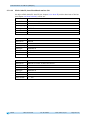
5.7
Directory of objects
5.7.1
Overview of objects
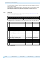
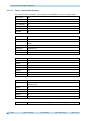
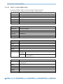
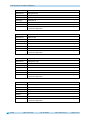
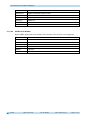
The following table offers an overview of the objects of the unit.
Name
Description
1000h: Device Type
1001h: Error Register
1002h: Manufacturer Status
Register
1003h: Pre-defined Error Field
Device profile and encoder type.
Current error state of the device.
Contains the Receive Error Counter and the Transmit
Error Counter.
The object stores the 8 error states that have
occurred last.
1005h: COB-ID SYNC message
Setting of the COB ID of the SYNC object.
1008h: Manufacturer Device Name Device name in in ASCII characters
1009h: Manufacturer Hardware
Indicates the hardware version of the device.
Version
100Ah: Manufacturer Software
Indicates the software version of the device.
Version
100Ch: Guard Time
Parameter for Node Guarding.
100Dh: Life Time Factor
Parameter for Node Guarding.
1010h: Store Parameter
Object for non-volatile storage of the settings.
1011h: Restore Parameter
Object for restoring the factory settings.
1014h: COB-ID Emergency Message COB ID of the Emergency message.
1017h: Producer Heartbeat Time
Setting of the cycle time of the heartbeat timer.
1018h: Identity Object
Contains the manufacturer number assigned by CiA.
1200h: Server SDO Parameter
SDO parameter
1400h: 1. Receive PDO Parameter Receive PDO1
1401h: 2. Receive PDO Parameter Receive PDO2
1600h: 1. Receive PDO Mapping
Describes the arrangement of the objects mapped in
Parameter
RPDO1.
1601h: 2. Receive PDO Mapping
Describes the arrangement of the objects mapped in
Parameter
RPDO2.
1800h: 1. Transmit PDO Parameter Transmit PDO for asynchronous transmission (timercontrolled).
1801h: 2. Transmit PDO Parameter Transmit PDO for synchronous transmission.
1A00h: 1. Transmit PDO Mapping Describes the arrangement of the objects mapped in
Parameter
TPDO1.
1A01h: 2. Transmit PDO Mapping Describes the arrangement of the objects mapped in
Parameter
TPDO2.
2001h: Manufacturer Offset
Manufacturer-specific offset value (is added to the
position value encoder-internally).
2002h: Calibrate encoder value
Set the position value to the calibration value.
AP10
Date: 07.04.2015
Art. No. 86853
Mod. status 132/15
see
page
33
34
34
34
35
36
36
36
37
37
37
40
42
42
43
44
45
46
47
48
49
51
52
53
54
54
Page 31 of 77
Communication via CAN bus (CANopen)
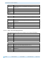
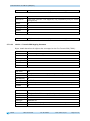
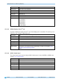
Name
Description
2003h: Calibration enable
2004h: Incremental measurement
enable
2005h: Configuration enable via
keyboard and delay of start of
configuration
5000h: Diagnosis of CAN bus errors
5F09h: External Heartbeat timer
and external Heartbeat source
5F0Ah: Node-ID, Auto-ID and Baud
rate Bus CAN
5F0Bh: Display in the 2nd row
5F0Ch: Control word
5F0Dh: Differential value and
difference formation
5F10h: Target window1 (near
field)
5F11h: Decimal places
5F12h: Display orientation and
LEDs
5F13h: Display divisor (ADI) and
ADI application
5F14h: Loop length
5F15h: Positioning type
5F16h: Read target value
5F17h: Period counter, sensor ADC
values and absolute fine value
see
page
Setting whether calibration of the display is enabled 55
via key actuation.
Setting whether setting of the incremental
55
measurement function is enabled via key actuation.
Setting whether configuration is enabled via key
55
operation. Delay of start of configuration.
Informs about CAN bus error events.
Cycle time and trigger source of the external
heartbeat.
Setting of Node-ID baud rate.
56
57
Setting of the display in the 2nd row.
Control word
Differential value and setting of difference
formation.
Setting of target window1 (close-up range).
59
59
60
Number of decimal places.
Setting of the display orientation and LED
functionality.
Setting of the display divisor and its application.
61
61
58
60
Setting of the loop length.
Setting of the loop type's direction of approach.
Read current target value; write access only via PDO.
Outputs the following current values:
Period counter, sensor ADC values and absolute fine
value.
5F19h: Status word
Output of the device status.
5F1Bh: Sensor type and operating Reading sensor type and setting of the operating
mode
mode (absolute, differential display, 360°, alphanumeric display).
5F1Ch: Acknowledgement settings Setting of the key to be used as acknowledgement
key (alpha-num. display).
5F1Fh: Direction indicators (CW,
Setting of the appearance of the direction arrows.
CCW)
5F21h: Target window2 (far) and Setting of target window2 and its visualization.
target window2 visualization
6000h: Operating Parameters
Setting of scaling and sense of rotation.
6001h: Measuring steps per
Setting of the measuring steps per revolution
revolution (Display per revolution displayed
= APU)
(Display per revolution = APU).
6002h: Total of measuring steps
Indicates the total of measuring steps of the system.
AP10
Date: 07.04.2015
Art. No. 86853
Mod. status 132/15
64
65
65
65
67
68
68
69
69
69
70
71
71
Page 32 of 77
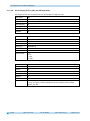
Communication via CAN bus (CANopen)
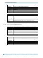
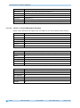
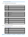
Name
Description
6003h: Preset value (calibration
value)
6004h: Position value
Setting of the calibration value.
6200h: Cycle Timer
6500h: Operating Status
6501h: Single-turn resolution
6502h: Number of distinguishable
revolutions
6503h: Alarms
6504h: Supported Alarms
6505h: Warnings
6506h: Supported Warnings
6507h: Profile and Software
Version
6508h: Operating Time
6509h: Encoder calibration value
650Ah: Module Identification
650Bh: Serial Number
see
page
71
Position value (offset against calibration and offset
value)
Identical with object 1800h, sub-index 5.
Output of scaling and sense of rotation.
Indicates the physical number of measuring steps per
revolution.
Indicates the number of revolutions the encoder is
able to scan.
Indication of error states.
Indicates which alarm messages are supported.
Indication of warnings.
Indicates which warnings are supported.
Indicates the version number of the device profile
used and the version number of the encoder's
firmware.
Counter of operating hours (function is not
supported)
Encoder status at the time of calibration.
Indicates the offset value as well as the smallest and
largest transferable position value.
Outputs the value FFFFFFFFh (function is not
supported).
72
72
72
73
73
73
74
74
75
75
75
76
76
77
Table 20: Overview of objects
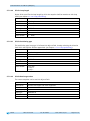
5.7.2
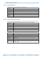
Description of objects
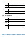
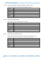
5.7.2.1
1000h: Device Type
Object 1000h indicates the device profile number.
Sub-index
Description
Access
PDO mapping
Data type
Default
EEPROM
Data content
AP10
00h
Information on device profile and device type
ro
no
UNSIGNED 32
00030196h
no
Device profile number
Encoder type
Byte 0
Byte 1
Byte 2
96h
01h
05h
Date: 07.04.2015
Art. No. 86853
Mod. status 132/15
Byte 3
00h
Page 33 of 77
Communication via CAN bus (CANopen)
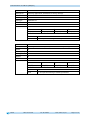
0196h (= 406): CANopen Device Profile for Encoders, Version 3.02
0005h: Incremental rotative encoder, with battery-buffered electronic period counter
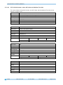
5.7.2.2
1001h: Error Register
Object 1001h indicates the error state of the device.
Sub-index
Description
Access
PDO mapping
Data type
Default
EEPROM
Data content
00h
currently existing error status
ro
no
UNSIGNED 8
0x00
no
Bit
Meaning
0
set bit indicates the occurrence of any error condition
4
set bit indicates communication error on the CAN bus
(Acknowledgement-, Form-, CRC- and Stuffbit)
7
manufacturer-specific (battery or sensor error)
1-3, 5-6 not used
Faults and errors are signalled at the time of their occurrence by an emergency message.
5.7.2.3
1002h: Manufacturer Status Register
The object 1002h shows the counter readings of "Transmit Error Counter" and "Receive Error
Counter". The contents of these registers provide information on the transmit faults present
at the mounting site of the encoder.
Sub-index
Description
Access
PDO mapping
Data type
Default
EEPROM
Data content
5.7.2.4
00h
Transmit Error Counter and Receive Error Counter
ro
no
UNSIGNED 32
0x0000
no
Byte 0
Byte 1
Byte 2
Receive Error Counter Transmit Error Counter
Byte 3
1003h: Pre-defined Error Field
The 8 error states that occurred last are archived in object 1003h (see chapter 5.5.1:
Emergency Service (EMCY)).
The entry under sub-index 0 indicates the number of stored errors.
AP10
Date: 07.04.2015
Art. No. 86853
Mod. status 132/15
Page 34 of 77
Communication via CAN bus (CANopen)
The latest error state is always stored in sub-index 1. Previous error messages are each
shifted one sub-index position farther.
The whole error list is deleted by writing the value 0 at sub-index 0.
The entries in the error list have the format described in chapter 5.5.1: Emergency Service
(EMCY).
5.7.2.5
Sub-index
Description
Access
PDO mapping
Data type
Default
EEPROM
00h
number of the error messages stored
rw
no
UNSIGNED 8
0
yes
Sub-index
Description
Access
PDO mapping
Data type
Default
EEPROM
01h-08h
error messages that occurred
ro
no
UNSIGNED 32
0
yes
1005h: COB-ID SYNC message
The COB-ID of the SYNC object is set via object 1005h.
Sub-index
Description
Access
PDO mapping
Data type
Default
EEPROM
Data content
AP10
00h
Defines the COB ID of the synchronization object (SYNC)
rw (writable in the "Pre-Operational" state only see chapter 5.1)
no
UNSIGNED 32
80h
yes
Bit 31
not defined
Bit 30
0: unit generates no SYNC message
Bit 29
0: 11bit identifier (CAN 2.0A)
1: 29bit identifier (CAN 2.0B)
Bit 28 … 11
0: if bit 29 = 0
X: bits 28 – 11 of the SYNC-COB-ID, if bit 29 = 1
Bit 10 … 0
X: bits 10 – 0 of the SYNC-COB-ID
Date: 07.04.2015
Art. No. 86853
Mod. status 132/15
Page 35 of 77
Communication via CAN bus (CANopen)
5.7.2.6
1008h: Manufacturer Device Name
Object 1008h indicates the device name.
Sub-index
Description
Access
PDO mapping
Data type
Default
EEPROM
Data content
5.7.2.7
00h
Device name as ASCII characters
Const
no
Visible_String
AP10
no
Byte 0
Byte 1
41h ("A")
50h ("P")
Byte 2
31h ("1")
Byte 3
30h ("0")
Byte 2
30h ("0")
Byte 3
31h ("1")
Byte 2
30h ("0")
Byte 3
30h ("0")
1009h: Manufacturer Hardware Version
Object 1009h indicates the hardware version.
Sub-index
Description
Access
PDO mapping
Data type
Default
EEPROM
Data content
5.7.2.8
00h
Hardware version as ASCII characters
Const
no
Visible_String
V001
no
Byte 0
Byte 1
56h ("V")
30h ("0")
100Ah: Manufacturer Software Version
Object 100Ah indicates the software version of the device.
Sub-index
Description
Access
PDO mapping
Data type
Default
EEPROM
Data content
AP10
00h
Software version as ASCII characters
Const
no
Visible_String
V100
no
Byte 0
Byte 1
56h ("V")
31h ("1")
Date: 07.04.2015
Art. No. 86853
Mod. status 132/15
Page 36 of 77
Communication via CAN bus (CANopen)
5.7.2.9
100Ch: Guard Time
The object 100Ch indicates the cycle time set in the master for Node Guarding (see chapter
5.5.2: Node Guarding). The cycle time is indicated in milliseconds. The value "0" means that
Node Guarding is deactivated.
Sub-index
Description
Access
PDO mapping
Data type
Default
EEPROM
5.7.2.10
00h
Guard Time
rw
no
UNSIGNED 16
0h
yes
100Dh: Life Time Factor
The object 100Dh indicates the Life Time Factor set in the master for Node Guarding (see
chapter 5.5.2: Node Guarding). The value "0" means that Node Guarding is deactivated.
Sub-index
Description
Access
PDO mapping
Data type
Default
EEPROM
5.7.2.11
00h
Life Time Factor
rw
no
UNSIGNED 8
0h
yes
1010h: Store Parameter
With this objects, parameter are transferred into the EEPROM in order to be available in case
of voltage failure. Different parameter groups are saved depending on the sub-index selected
for access. The string "save" as data content must also be sent.
Sub-index
Description
Access
PDO mapping
Data type
Default
EEPROM
AP10
00h
indicates the largest sub-index supported
ro
no
UNSIGNED 8
4h
no
Date: 07.04.2015
Art. No. 86853
Mod. status 132/15
Page 37 of 77
Communication via CAN bus (CANopen)
AP10
Subindex
Beschreibung
Access
PDO mapping
Data type
Default
EEPROM
Data content
01h
save all parameters
rw
no
UNSIGNED 32
1h
no
Write:
Byte 0
Byte 1
Byte 2
Byte 3
73h ("s")
61h ("a")
76h ("v")
65h ("e")
Read:
Bit 31 … 2
0, reserved
Bit 1
0: device does not save parameters autonomously
Bit 0
1: unit stores parameter by command
Sub-index
Description
Access
PDO mapping
Data type
Default
EEPROM
Data content
02h
save only communication parameters (1000h-1FFFh, DS301)
rw
no
UNSIGNED 32
1h
no
Write:
Byte 0
Byte 1
Byte 2
Byte 3
73h ("s")
61h ("a")
76h ("v")
65h ("e")
Read:
Bit 31 … 2
0, reserved
Bit 1
0: device does not save parameters autonomously
Bit 0
1: unit stores parameter by command
Date: 07.04.2015
Art. No. 86853
Mod. status 132/15
Page 38 of 77
Communication via CAN bus (CANopen)
AP10
Sub-index
Description
Access
PDO mapping
Data type
Default
EEPROM
Data content
03h
save only application parameters (6000h-9FFFh, DS406)
rw
no
UNSIGNED 32
1h
no
Write:
Byte 0
Byte 1
Byte 2
Byte 3
73h ("s")
61h ("a")
76h ("v")
65h ("e")
Read:
Bit 31 … 2
0, reserved
Bit 1
0: device does not save parameters autonomously
Bit 0
1: unit stores parameter by command
Sub-index
Description
Access
PDO mapping
Data type
Default
EEPROM
Data content
04h
save only manufacturer-specific parameters (2000h-5FFFh)
rw
no
UNSIGNED 32
1h
no
Write:
Byte 0
Byte 1
Byte 2
Byte 3
73h ("s")
61h ("a")
76h ("v")
65h ("e")
Read:
Bit 31 … 2
0, reserved
Bit 1
0: device does not save parameters autonomously
Bit 0
1: unit stores parameter by command
Date: 07.04.2015
Art. No. 86853
Mod. status 132/15
Page 39 of 77
Communication via CAN bus (CANopen)
5.7.2.12
1011h: Restore Parameter
The object 1011h restores the factory settings of the device depending on the selection. The
string "load" must be sent as data content and reset executed afterwards. If the restored
parameters must be available permanently, they must be saved via object 1010h: Store
Parameter.
AP10
Sub-index
Description
Access
PDO mapping
Data type
Default
EEPROM
00h
indicates the largest supported sub-index
ro
no
UNSIGNED 8
4h
no
Sub-index
Description
Access
PDO mapping
Data type
Default
EEPROM
Data content
01h
reset all parameters to factory settings
rw
no
UNSIGNED 32
1h
no
Write:
Byte 0
Byte 1
Byte 2
Byte 3
6Ch ("l")
6Fh ("o")
61h ("a")
64h ("d")
Read:
Bit 31 … 1
0, reserved
Bit 0
1: unit permits loading of default parameters
Sub-index
Description
Access
PDO mapping
Data type
Default
EEPROM
Data content
02h
reset only communication parameters to factory settings
rw
no
UNSIGNED 32
1h
no
Write:
Byte 0
Byte 1
Byte 2
Byte 3
6Ch ("l")
6Fh ("o")
61h ("a")
64h ("d")
Read:
Bit 31 … 1
0, reserved
Bit 0
1: unit permits loading of default parameters
Date: 07.04.2015
Art. No. 86853
Mod. status 132/15
Page 40 of 77
Communication via CAN bus (CANopen)
AP10
Sub-index
Description
Access
PDO mapping
Data type
Default
EEPROM
Data content
03h
reset only application parameters to factory settings
rw
no
UNSIGNED 32
1h
no
Write:
Byte 0
Byte 1
Byte 2
Byte 3
6Ch ("l")
6Fh ("o")
61h ("a")
64h ("d")
Read:
Bit 31 … 1
0, reserved
Bit 0
1: unit permits loading of default parameters
Sub-index
Description
Access
PDO mapping
Data type
Default
EEPROM
Data content
04h
reset only manufacturer-specific parameters to factory settings
rw
no
UNSIGNED 32
1h
no
Write:
Byte 0
Byte 1
Byte 2
Byte 3
6Ch ("l")
6Fh ("o")
61h ("a")
64h ("d")
Read:
Bit 31 … 1
0, reserved
Bit 0
1: unit permits loading of default parameters
Date: 07.04.2015
Art. No. 86853
Mod. status 132/15
Page 41 of 77
Communication via CAN bus (CANopen)
5.7.2.13
1014h: COB-ID Emergency Message
The COB-ID of the Emergency object is set via object 1014h (see chapter 5.5.1: Emergency
Service (EMCY)).
Sub-index
Description
Access
PDO mapping
Data type
Default
EEPROM
Data content
5.7.2.14
00h
Defines the COB ID of the Emergency object (EMCY)
rw (writable in the "Pre-Operational" state only see chapter 5.2: Node
control)
no
UNSIGNED 32
80h + Node-ID
yes
Bit 31
0: EMCY object exists / is valid
1: EMCY object does not exists / is invalid
Bit 30
ever 0
Bit 29
0: 11bit identifier (CAN 2.0A)
1: 29bit identifier (CAN 2.0B)
Bit 28 … 11 0: if bit 29 = 0
X: bits 28 – 11 of the EMCY-COB-ID, if bit 29 = 1
Bit 10 … 0
X: bits 10 – 0 of the EMCY -COB-ID
1017h: Producer Heartbeat Time
The cycle time "Heartbeat Time" for the heartbeat protocol is set via object 1017h. The cycle
time is indicated in milliseconds.
Sub-index
Description
Access
PDO mapping
Data type
Default
EEPROM
Data content
AP10
00h
defines the cycle time of the heartbeat monitoring service
rw
no
UNSIGNED 16
0
yes
0, 10 ... 65535 (0h, Ah ... FFFFh); the numerical value corresponds to a
multiple of 1 ms. The value 0 deactivates the service.
Date: 07.04.2015
Art. No. 86853
Mod. status 132/15
Page 42 of 77
Communication via CAN bus (CANopen)
5.7.2.15
1018h: Identity Object
The manufacturer identification number (Vendor ID) is indicated via object 1018h.
Sub-index
Description
Access
PDO mapping
Data type
Default
EEPROM
00h
indicates the largest sub-index supported
ro
no
UNSIGNED 8
4h
no
Sub-index
Description
01h
the manufacturer identification number (vendor ID) for the company SIKO
GmbH allocated by the CiA
ro
no
UNSIGNED 32
195h
no
Access
PDO mapping
Data type
Default
EEPROM
Sub-index
Description
Access
PDO mapping
Data type
Default
EEPROM
Sub-index
Description
Access
PDO mapping
Data type
Default
EEPROM
AP10
02h
Product Code (function is not supported, only compatibility entry for
various configurators)
ro
no
UNSIGNED 32
0h
no
03h
Revision Number (Function is not supported, only compatibility entry for
various configurators)
ro
no
UNSIGNED 32
0h
no
Date: 07.04.2015
Art. No. 86853
Mod. status 132/15
Page 43 of 77
Communication via CAN bus (CANopen)
Sub-index
Description
Access
PDO mapping
Data type
Default
EEPROM
5.7.2.16
04h
Serial Number (Function is not supported, only compatibility entry for
various configurators)
ro
no
UNSIGNED 32
FFFF FFFFh
no
1200h: Server SDO Parameter
The COB IDs for the Default Server SDO are indicated via object 1200h. The COB-IDs cannot be
changed.
AP10
Sub-index
Description
Access
PDO mapping
Data type
Default
EEPROM
00h
indicates the largest sub-index supported
ro
no
UNSIGNED 8
2h
no
Sub-index
Description
Access
PDO mapping
Data type
Default
EEPROM
01h
COB-ID Client -> Server (rx)
ro
no
UNSIGNED 32
00000600h + Node-ID
no
Sub-index
Description
Access
PDO mapping
Data type
Default
EEPROM
02h
COB-ID Server -> Client (tx)
ro
no
UNSIGNED 32
00000580h + Node-ID
no
Date: 07.04.2015
Art. No. 86853
Mod. status 132/15
Page 44 of 77
Communication via CAN bus (CANopen)
5.7.2.17
1400h: 1. Receive PDO Parameter
The communication parameters of the first Receive PDO (RPDO1) are set via object 1400h.
AP10
Sub-index
Description
Access
PDO mapping
Data type
Default
EEPROM
00h
indicates the largest sub-index supported
ro
no
UNSIGNED 8
5h
no
Sub-index
Description
Access
PDO mapping
Data type
Default
EEPROM
01h
COB-ID des PDO1
rw (writable in the "Pre-Operational" state only see chapter 5.1: Telegram
setup)
no
UNSIGNED 32
200h + Node-ID
yes
Sub-index
Description
Access
PDO mapping
Data type
Default
EEPROM
Data content
02h
Transmission Type
rw
no
UNSIGNED 8
FFh
yes
0h … F0h, FEh, FFh
Sub-index
Description
Access
PDO mapping
Data type
Default
EEPROM
03h
Inhibit time (function is not supported, only compatibility entry for various
configurators)
ro
no
UNSIGNED 16
0h
no
Sub-index
04h (is not used, access attempt generates error message)
Date: 07.04.2015
Art. No. 86853
Mod. status 132/15
Page 45 of 77
Communication via CAN bus (CANopen)
Sub-index
Description
Access
PDO mapping
Data type
Default
EEPROM
5.7.2.18
05h
Event timer (function is not supported, only compatibility entry for various
configurators)
ro
no
UNSIGNED 16
0h
no
1401h: 2. Receive PDO Parameter
The communication parameters of the second Receive-PDOs (RPDO2) are set via object 1401h.
AP10
Sub-index
Description
Access
PDO mapping
Data type
Default
EEPROM
00h
indicates the largest sub-index supported
ro
no
UNSIGNED 8
5h
no
Sub-index
Description
Access
PDO mapping
Data type
Default
EEPROM
01h
COB-ID of the PDO2
rw (writable in the "Pre-Operational" state only see chapter 5.1)
no
UNSIGNED 32
300h + Node-ID
yes
Sub-index
Description
Access
PDO mapping
Data type
Default
EEPROM
Data content
02h
Transmission Type
rw
no
UNSIGNED 8
FFh
yes
0h … F0h, FEh, FFh
Date: 07.04.2015
Art. No. 86853
Mod. status 132/15
Page 46 of 77
Communication via CAN bus (CANopen)
Sub-index
Description
Access
PDO mapping
Data type
Default
EEPROM
03h
Inhibit time (function is not supported, only compatibility entry for various
configurators)
ro
no
UNSIGNED 16
0h
no
Sub-index
04h (is not used, access attempt generates error message)
Sub-index
Description
05h
Event timer (function is not supported, only compatibility entry for various
configurators)
ro
no
UNSIGNED 16
0h
no
Access
PDO mapping
Data type
Default
EEPROM
5.7.2.19
1600h: 1. Receive PDO Mapping Parameter
Object 1600h determines the objects that are mapped on the first Receive PDO (RPDO1).
AP10
Sub-index
Description
Access
PDO mapping
Data type
Default
EEPROM
00h
number of objects mapped
ro
no
UNSIGNED 8
3h
no
Sub-index
Description
Access
PDO mapping
Data type
Default
EEPROM
01h
1st object of the PD01 message (Data byte 0 until 3)
ro
no
UNSIGNED 32
0x5F160320 (Setpoint object 5F16h, Sub-index 0x03, 32bit)
no
Date: 07.04.2015
Art. No. 86853
Mod. status 132/15
Page 47 of 77
Communication via CAN bus (CANopen)
5.7.2.20
Sub-index
Description
Access
PDO mapping
Data type
Default
EEPROM
02h
2nd object of the PD01 message (Data byte 4+5)
ro
no
UNSIGNED 32
0x5F160410 (Setpoint object 5F16h, Sub-index 0x04, 16bit)
no
Sub-index
Description
Access
PDO mapping
Data type
Default
EEPROM
03h
3rd object of the PD01 message (Data byte 6+7)
ro
no
UNSIGNED 32
0x5F0C0010 (Control word object 5F0Ch, Sub-index 0x00, 16bit)
no
1601h: 2. Receive PDO Mapping Parameter
Object 1601h determines the objects that are mapped on the second Receive PDO (RPDO2).
AP10
Sub-index
Description
Access
PDO mapping
Data type
Default
EEPROM
00h
number of objects mapped
ro
no
UNSIGNED 8
3h
no
Sub-index
Description
Access
PDO mapping
Data type
Default
EEPROM
01h
1st object of the PD02 message (Data byte 0 until 3)
ro
no
UNSIGNED 32
0x5F160120 (Setpoint object 5F16h, Sub-index 0x01, 32bit)
no
Date: 07.04.2015
Art. No. 86853
Mod. status 132/15
Page 48 of 77
Communication via CAN bus (CANopen)
5.7.2.21
Sub-index
Description
Access
PDO mapping
Data type
Default
EEPROM
02h
2nd object of the PD02 message (Data byte 4+5)
ro
no
UNSIGNED 32
0x5F160210 (Setpoint object 5F16h, Sub-index 0x02, 16bit)
no
Sub-index
Description
Access
PDO mapping
Data type
Default
EEPROM
03h
3rd object of the PD02 message (Data byte 6+7)
ro
no
UNSIGNED 32
0x5F0C0010 (Control word object 5F0Ch, Sub-index 0x00, 16bit)
no
1800h: 1. Transmit PDO Parameter
According to DS406, TPDO1 is used for asynchronous PDO transmission.
The communication parameters are set for TPDO1 via object 1800h.
AP10
Sub-index
Description
Access
PDO mapping
Data type
Default
EEPROM
00h
indicates the largest sub-index supported
ro
no
UNSIGNED 8
5h
no
Sub-index
Description
Access
PDO mapping
Data type
Default
EEPROM
01h
COB-ID des PDO1
rw (writable in the "Pre-Operational" state only see chapter 5.1)
no
UNSIGNED 32
180h + Node-ID
yes
Date: 07.04.2015
Art. No. 86853
Mod. status 132/15
Page 49 of 77
Communication via CAN bus (CANopen)
AP10
Sub-index
Description
Access
PDO mapping
Data type
Default
EEPROM
Data content
02h
Transmission Type
rw
no
UNSIGNED 8
FEh (254)
yes
FEh (254)
PDO has asynchronous characteristics (PDO is sent depending
FFh (255)
on the "Event Timer").
FDh (253)
Device responds to RTR-request only if RTR Bit 30 is enabled
in the COB-ID.
Sub-index
Description
Access
PDO mapping
Data type
Default
EEPROM
03h
Inhibit time (function is not supported, only compatibility entry for various
configurators)
ro
no
UNSIGNED 16
0h
no
Sub-index
04h (is not used, access attempt generates error message)
Sub-index
Description
Access
PDO mapping
Data type
Default
EEPROM
Data content
05h
Event timer for TPDO1 hard-wired (DS406) with cyclic timer 6200h
rw
no
UNSIGNED 16
0h
yes
The service is disabled by writing the value 0. The content of this object is
identical with object 6200h. If the value is changed while the timer is
running, then the change will take effect only with the next timer run.
Sub-index
06h (is not used, access attempt generates error message)
Date: 07.04.2015
Art. No. 86853
Mod. status 132/15
Page 50 of 77
Communication via CAN bus (CANopen)
5.7.2.22
1801h: 2. Transmit PDO Parameter
According to DS406, TPDO2 is used for synchronous PDO transmission.
The communication parameters are set for TPDO2 via object 1801h.
Sub-index
Description
Access
PDO mapping
Data type
Default
EEPROM
00h
indicates the largest sub-index supported
ro
no
UNSIGNED 8
5h
no
Sub-index
Description
Access
PDO mapping
Data type
Default
EEPROM
01h
COB-ID of the PDO2
rw (writable in the "Pre-Operational" state only see chapter 5.1)
no
UNSIGNED 32
280h + Node-ID
yes
Sub-index
Description
Access
PDO mapping
Data type
Default
EEPROM
Data content
02h
Transmission Type
rw
no
UNSIGNED 8
1h
yes
FEh (254)
PDO is sent after receipt of 1 ... 240 SYNC messages.
FFh (255)
FDh (253)
Device responds to RTR-request only if RTR Bit 30 is enabled
in the COB-ID.
Sub-index
Description
03h
Inhibit time (function is not supported, only compatibility entry for various
configurators)
ro
no
UNSIGNED 16
0h
no
Access
PDO mapping
Data type
Default
EEPROM
AP10
Date: 07.04.2015
Art. No. 86853
Mod. status 132/15
Page 51 of 77
Communication via CAN bus (CANopen)
5.7.2.23
Sub-index
04h (is not used, access attempt generates error message)
Sub-index
Description
Access
PDO mapping
Data type
Default
EEPROM
05h
Event timer (function is not supported, only compatibility entry for various
configurators)
ro
no
UNSIGNED 16
0h
no
Sub-index
06h (is not used, access attempt generates error message)
1A00h: 1. Transmit PDO Mapping Parameter
Object 1A00h determines the objects that are mapped on the first Transmit PDO (TPDO1).
AP10
Sub-index
Description
Access
PDO mapping
Data type
Default
EEPROM
00h
number of objects mapped
ro
no
UNSIGNED 8
2h
no
Sub-index
Description
Access
PDO mapping
Data type
Default
EEPROM
01h
1st object of the PDO1 message (Data byte 0 until 3)
ro
no
UNSIGNED 32
60040020h (Position value object 6004h, Sub-index 0x00, 32bit)
no
Sub-index
Description
Access
PDO mapping
Data type
Default
EEPROM
02h
2nd object of the PDO1 message (Data byte 4+5)
ro
no
UNSIGNED 32
5F1D0010h (Dummy object 5F1D, Sub-index 0x00, 16bit)
no
Date: 07.04.2015
Art. No. 86853
Mod. status 132/15
Page 52 of 77
Communication via CAN bus (CANopen)
Sub-index
Description
Access
PDO mapping
Data type
Default
EEPROM
5.7.2.24
03h
3rd object of the PDO1 message (Data byte 6+7)
ro
no
UNSIGNED 32
5F190010h (Status word object 5F19h, Sub-index 0x00, 16bit)
no
1A01h: 2. Transmit PDO Mapping Parameter
Object 1A01h determines the objects that are mapped on the second Receive PDOs (TPDO2).
AP10
Sub-index
Description
Access
PDO mapping
Data type
Default
EEPROM
00h
number of objects mapped
ro
no
UNSIGNED 8
2h
no
Sub-index
Description
Access
PDO mapping
Data type
Default
EEPROM
01h
1st Object of the PDO2 message (Data byte 0 until 3)
ro
no
UNSIGNED 32
0x60040020 (Position value object 6004h, Sub-index 0x00, 32bit)
no
Sub-index
Description
Access
PDO mapping
Data type
Default
EEPROM
02h
2nd Object of the PDO2 message (Data byte 4+5)
ro
no
UNSIGNED 32
5F1D0010h (Dummy object 5F1D, Sub-index 0x00, 16bit)
no
Date: 07.04.2015
Art. No. 86853
Mod. status 132/15
Page 53 of 77
Communication via CAN bus (CANopen)
Sub-index
Description
Access
PDO mapping
Data type
Default
EEPROM
5.7.2.25
03h
3rd Object of the PDO2 message (Data byte 6+7)
ro
no
UNSIGNED 32
5F190010h (Status word object 5F19h, Sub-index 0x00, 16bit)
no
2001h: Manufacturer Offset
The offset value is determined via object 2001h.
Sub-index
Description
Access
PDO mapping
Data type
Default
EEPROM
Data content
5.7.2.26
00h
The offset enables the shifting of a scaled value range. The offset value is
added to the position value in the encoder. Positive as well as negative
values are permitted.
Position value = measured value + calibration value + offset value
rw
no
SIGNED 16
0h
yes
-9999 … 9999
2002h: Calibrate encoder value
Via object 2002h, calibration can be executed or information given whether calibration was
executed.
Sub-index
Description
Access
PDO mapping
Data type
Default
EEPROM
Data content
AP10
00h
The object enables "zeroing" of the measured value. The position value is
set to the calibration value thereby.
Position value = measured value + calibration value + offset value
rw
no
UNSIGNED 8
0h
yes
Object 2002h read:
0, 2
2 is fed back with a read access if calibration took place
beforehand.
Object 2002h write:
1
Writing the value 1 sets the position value to the calibration value.
Date: 07.04.2015
Art. No. 86853
Mod. status 132/15
Page 54 of 77
Communication via CAN bus (CANopen)
5.7.2.27
2003h: Calibration enable
The object 2003h indicates whether calibration of the position value is enabled via key
actuation.
Sub-index
Description
Access
PDO mapping
Data type
Default
EEPROM
Data content
5.7.2.28
00h
Key enable
rw
no
UNSIGNED 8
1h
ja
0: Calibration disabled
1: Calibration enabled
2004h: Incremental measurement enable
The object 2004h indicates whether setting of the position value as incremental measurement
is enabled via key actuation.
Sub-index
Description
Access
PDO mapping
Data type
Default
EEPROM
Data content
5.7.2.29
00h
Key enable
rw
no
UNSIGNED 8
1h
yes
0: Incremental measurement disabled
1: Incremental measurement enabled
2005h: Configuration enable via keyboard and delay of start of configuration
Object 2005h indicates whether configuration via key actuation is enabled. The delay of start
of configuration is set in sub-index 2 (key enable time).
Sub-index
Description
Access
PDO mapping
Data type
Default
EEPROM
AP10
00h
indicates the largest sub-index supported
ro
no
UNSIGNED 8
2h
no
Date: 07.04.2015
Art. No. 86853
Mod. status 132/15
Page 55 of 77
Communication via CAN bus (CANopen)
5.7.2.30
Sub-index
Description
Access
PDO mapping
Data type
Default
EEPROM
Data content
01h
Key enable
rw
no
UNSIGNED 8
1h
yes
0: disabled (is not supported)
1: enabled
Sub-index
Description
Access
PDO mapping
Data type
Default
EEPROM
Data content
02h
delay of start of configuration (key enable time)
rw
no
UNSIGNED 8
5h
yes
1 … 60 s
5000h: Diagnosis of CAN bus errors
A prioritized list of CAN bus errors occurring can be read via object 5000h.
Sub-index
Description
Access
PDO mapping
Data type
Default
EEPROM
Data content
00h
Indicates the CAN Bus errors Acknowledge, Form, CRC and Stuff Error sorted
by frequency.
ro
no
UNSIGNED 32
0h
no
Byte 0
Byte 1
Byte 2
Byte 3
General Acknowledgement Form error
CRC error
Stuff error
error
0, 1, 2, 3, 4
0, 1, 2, 3, 4
0, 1, 2, 3, 4 0, 1, 2, 3, 4
Explanation of the data content:
0: Error does not occur at all
4: Error occurs most frequently
AP10
Date: 07.04.2015
Art. No. 86853
Mod. status 132/15
Page 56 of 77
Communication via CAN bus (CANopen)
5.7.2.31
5F09h: External Heartbeat timer and external Heartbeat source
Via object 5F09h, an external heartbeat timer and its trigger source can be set. This function
serves for monitoring the connection of the device to the master via CAN bus.
Sub-index
Description
Access
PDO mapping
Data type
Default
EEPROM
00h
indicates the largest sub-index supported
ro
no
UNSIGNED 8
2h
no
Sub-index
Description
01h
With a value greater than zero entered here, an event depending on the
external heartbeat source set in sub-index 2 is expected in this interval. If
no such event is received, the device will return to the "Pre-Operational"
status.
rw
no
UNSIGNED 8
0h
yes
0, 10 ... 65535 (Ah ... FFFFh); the numerical value corresponds to a
multiple of 1 ms. The function is disabled by writing the value 0.
Access
PDO mapping
Data type
Default
EEPROM
Data content
Sub-index
Description
Access
PDO mapping
Data type
Default
EEPROM
Data content
AP10
02h
Source that triggers the external heartbeat timer in sub-index 1
rw
no
UNSIGNED 8
0h
yes
0: Timer is triggered upon receipt of a PDO (setpoint)
1: Timer is triggered upon receipt of a SYNC
Date: 07.04.2015
Art. No. 86853
Mod. status 132/15
Page 57 of 77
Communication via CAN bus (CANopen)
5.7.2.32
5F0Ah: Node-ID, Auto-ID and Baud rate Bus CAN
Via object 5F0Ah, Node-ID, Auto-ID (see chapter 5.6.2: Auto-ID) and the baud rate of the bus
(see chapter 5.6: Auto functions) can be set.
AP10
Sub-index
Description
Access
PDO mapping
Data type
Default
EEPROM
00h
indicates the largest sub-index supported
ro
no
UNSIGNED 8
3h
no
Sub-index
Description
Access
PDO mapping
Data type
Default
EEPROM
Data content
01h
Node-ID
rw
no
UNSIGNED 8
7Dh (125)
yes
1 … 7Fh
Sub-index
Description
Access
PDO mapping
Data type
Default
EEPROM
Data content
02h
Node-ID for access via Auto-ID function
rw
no
UNSIGNED 8
yes
1 … 7Fh
Date: 07.04.2015
Art. No. 86853
Mod. status 132/15
Page 58 of 77
Communication via CAN bus (CANopen)
Sub-index
Description
Access
PDO mapping
Data type
Default
EEPROM
Data content
5.7.2.33
03h
Baud rate of the CAN bus
rw
no
UNSIGNED 8
0 (Auto baud)
yes
0: Auto baud
1: 125 kbaud
2: 250 kbaud
3: 500 kbaud
4: 800 kbaud
5: 1000 kbaud
5F0Bh: Display in the 2nd row
Via object 5F0Bh the display of the 2nd row of the display unit is controlled. The setting is not
effective in the "Display" operating mode.
Sub-index
Description
Access
PDO mapping
Data type
Default
EEPROM
Data content
5.7.2.34
00h
controls the display of the 2nd row of the display unit
rw
no
UNSIGNED 8
0h
no
0: Setpoint or differential value (depending on mode, see chapter 4.1.1:
Position-bound operating modes)
1: Off
5F0Ch: Control word
The control word can be read via object 5F0Ch. Write access is only via RPDO1 or RPDO2 (see
chapter 5.3.2: Control word).
Sub-index
Description
Access
PDO mapping
Data type
Default
EEPROM
AP10
00h
Control word
ro
yes
UNSIGNED 16
0h
no
Date: 07.04.2015
Art. No. 86853
Mod. status 132/15
Page 59 of 77
Communication via CAN bus (CANopen)
5.7.2.35
5F0Dh: Differential value and difference formation
The differential value can be read via object 5F0Dh sub-index. The differential value is set by
sub-index 2.
5.7.2.36
Sub-index
Description
Access
PDO mapping
Data type
Default
EEPROM
00h
indicates the largest sub-index supported
ro
no
UNSIGNED 8
2h
no
Sub-index
Description
Access
PDO mapping
Data type
Default
EEPROM
01h
differential value
ro
no
UNSIGNED 32
0h
no
Sub-index
Description
Access
PDO mapping
Data type
Default
EEPROM
Data content
02h
formation of the differential value
rw
no
UNSIGNED 8
0h
yes
0: DIFF = ACT – SET
1: DIFF = SET - ACT
5F10h: Target window1 (near field)
Object 5F10h indicates the window within which the setpoint is considered reached (see
chapter 4.1.1.1: Positioning).
Sub-index
Description
Access
PDO mapping
Data type
Default
EEPROM
Data content
AP10
00h
The setpoint is reached when the actual value is within the target window.
rw
no
UNSIGNED 16
5h
yes
0 … 9999
Date: 07.04.2015
Art. No. 86853
Mod. status 132/15
Page 60 of 77
Communication via CAN bus (CANopen)
5.7.2.37
5F11h: Decimal places
The object 5F11h indicates the number of decimal places.
Sub-index
Description
Access
PDO mapping
Data type
Default
EEPROM
Data content
5.7.2.38
00h
number of decimal places
rw
no
UNSIGNED 8
0h
yes
0…4
5F12h: Display orientation and LEDs
Settings of the display orientation and the LEDs can be made via object 5F12h. Furthermore
the function of the display backlighting can be set (see chapter 3.3: LED display).
AP10
Sub-index
Description
Access
PDO mapping
Data type
Default
EEPROM
00h
indicates the largest sub-index supported
ro
no
UNSIGNED 8
9h
no
Sub-index
Description
Access
PDO mapping
Data type
Default
EEPROM
Data content
01h
Display orientation
rw
no
UNSIGNED 8
0h
yes
0 = 0°
1 = 180° rotated
Date: 07.04.2015
Art. No. 86853
Mod. status 132/15
Page 61 of 77
Communication via CAN bus (CANopen)
AP10
Sub-index
Description
Access
PDO mapping
Data type
Default
EEPROM
Data content
02h
LED1 green left
rw
no
UNSIGNED 8
1h
yes
0: Off
1: position-dependent
Sub-index
Description
Access
PDO mapping
Data type
Default
EEPROM
Data content
03h
LED2 red left
rw
no
UNSIGNED 8
1h
yes
0: Off
1: position-dependent
Sub-index
Description
Access
PDO mapping
Data type
Default
EEPROM
Data content
04h
LED3 green right
rw
no
UNSIGNED 8
1h
yes
0: Off
1: position-dependent
Sub-index
Description
Access
PDO mapping
Data type
Default
EEPROM
Data content
05h
LED4 red right
rw
no
UNSIGNED 8
1h
yes
0: Off
1: position-dependent
Date: 07.04.2015
Art. No. 86853
Mod. status 132/15
Page 62 of 77
Communication via CAN bus (CANopen)
AP10
Sub-index
Description
Access
PDO mapping
Data type
Default
EEPROM
Data content
06h
FLASH LED
rw
no
UNSIGNED 8
0h
yes
0: Off
1: On
Sub-index
Description
Access
PDO mapping
Data type
Default
EEPROM
Data content
07h
white backlight
rw
no
UNSIGNED 8
1h
yes
0: Off
1: On
Sub-index
Description
Access
PDO mapping
Data type
Default
EEPROM
Data content
08h
red backlight
rw
no
UNSIGNED 8
1h
yes
0: Off
1: On
Sub-index
Description
Access
PDO mapping
Data type
Default
EEPROM
Data content
09h
FLASH backlight
rw
no
UNSIGNED 8
0h
yes
0: Off
1: On
Date: 07.04.2015
Art. No. 86853
Mod. status 132/15
Page 63 of 77
Communication via CAN bus (CANopen)
5.7.2.39
5F13h: Display divisor (ADI) and ADI application
The display divisor and its application can be changed via object 5F13h.
AP10
Sub-index
Description
Access
PDO mapping
Data type
Default
EEPROM
00h
indicates the largest sub-index supported
ro
no
UNSIGNED 8
2h
no
Sub-index
Description
Access
PDO mapping
Data type
Default
EEPROM
Data content
01h
display divisor ADI
rw
no
UNSIGNED 8
0h
yes
0: 1
1: 10
2: 100
3: 1000
Sub-index
Description
Access
PDO mapping
Data type
Default
EEPROM
Data content
02h
ADI application
rw
no
UNSIGNED 8
2h
yes
0: on all values
1: only on display. Values transferred via the interface are not offset
against the ADI.
Date: 07.04.2015
Art. No. 86853
Mod. status 132/15
Page 64 of 77
Communication via CAN bus (CANopen)
5.7.2.40
5F14h: Loop length
Object 5F14h specifies the loop length by which the setpoint shall be moved over with loop
travel (see chapter 4.1.1.2: Loop positioning).
Sub-index
Description
Access
PDO mapping
Data type
Default
EEPROM
Data content
5.7.2.41
00h
loop length
rw
no
UNSIGNED 16
0h
yes
0 … 9999
5F15h: Positioning type
The positioning type, loop type is indicated via object 5F15h, thereby selecting the direction
from which the setpoint shall be approached (see chapter 4.1.1.2: Loop positioning).
Sub-index
Description
Access
PDO mapping
Data type
Default
EEPROM
Data content
5.7.2.42
00h
Setpoint is approached in this direction.
rw
no
UNSIGNED 8
0h
yes
0: no loop
1: loop +
2: loop -
5F16h: Read target value
The current setpoints can be read via object 5F16h.
Sub-index
Description
Access
PDO mapping
Data type
Default
EEPROM
AP10
00h
indicates the largest sub-index supported
ro
no
UNSIGNED 8
4h
no
Date: 07.04.2015
Art. No. 86853
Mod. status 132/15
Page 65 of 77
Communication via CAN bus (CANopen)
AP10
Sub-index
Description
Access
PDO mapping
Data type
Default
EEPROM
01h
Set point2 (4 LSB Bytes)
ro
yes
UNSIGNED 32
0h
no
Sub-index
Description
Access
PDO mapping
Data type
Default
EEPROM
02h
Set point2 (2 MSB Bytes)
ro
yes
UNSIGNED 32
0h
no
Sub-index
Description
Access
PDO mapping
Data type
Default
EEPROM
03h
Set point1 (4 LSB Bytes)
ro
yes
UNSIGNED 32
0h
no
Sub-index
Description
Access
PDO mapping
Data type
Default
EEPROM
04h
Set point1 (2 MSB Bytes)
ro
yes
UNSIGNED 32
0h
no
Date: 07.04.2015
Art. No. 86853
Mod. status 132/15
Page 66 of 77
Communication via CAN bus (CANopen)
5.7.2.43
5F17h: Period counter, sensor ADC values and absolute fine value
The current values of the period counter, the ADC values and the absolute fine value can be
queried via object 5F17h.
AP10
Sub-index
Description
Access
PDO mapping
Data type
Default
EEPROM
00h
indicates the largest sub-index supported
ro
no
UNSIGNED 8
3h
no
Sub-index
Description
Access
PDO mapping
Data type
Default
EEPROM
Data content
01h
values of the period counter
ro
no
UNSIGNED 32
0h
no
Byte 0
Byte 1
Quadrant
Period counter
Sub-index
Description
Access
PDO mapping
Data type
Default
EEPROM
Data content
02h
sensor ADC values
ro
no
UNSIGNED 32
0h
no
Byte 0
ADC_SIN
Sub-index
Description
Access
PDO mapping
Data type
Default
EEPROM
03h
absolute fine value
ro
no
SIGNED 16
0h
no
Date: 07.04.2015
Byte 1
Art. No. 86853
Byte 2
Byte 3
Byte 2
ADC_COS
Byte 3
Mod. status 132/15
Page 67 of 77
Communication via CAN bus (CANopen)
5.7.2.44
5F19h: Status word
Object 5F19h informs about the current device status (see chapter 5.3.3: Status word).
Sub-index
Description
Access
PDO mapping
Data type
Default
EEPROM
5.7.2.45
00h
The status word informs about the current device status.
ro
yes
UNSIGNED 16
0h
no
5F1Bh: Sensor type and operating mode
The sensor type can be read and the operating mode changed via object 5F1Bh.
AP10
Sub-index
Description
Access
PDO mapping
Data type
Default
EEPROM
00h
indicates the largest sub-index supported
ro
no
UNSIGNED 8
2h
no
Sub-index
Description
Access
PDO mapping
Data type
Default
EEPROM
01h
read sensor type
ro
no
UNSIGNED 8
2h (internal sensor)
yes
Sub-index
Description
Access
PDO mapping
Data type
Default
EEPROM
Data content
02h
operating mode
rw
no
UNSIGNED 8
0h
no
0: Absolute position
1: Difference
2: Modulo (360° angle display)
3: Alpha-numeric display
Date: 07.04.2015
Art. No. 86853
Mod. status 132/15
Page 68 of 77
Communication via CAN bus (CANopen)
5.7.2.46
5F1Ch: Acknowledgement settings
Object 5F1Ch serves for determining the key to be used as acknowledgement key. The setting
is only relevant in the alpha-numeric display mode.
Sub-index
Description
Access
PDO mapping
Data type
Default
EEPROM
Data content
5.7.2.47
00h
acknowledgement settings
rw
no
UNSIGNED 8
0h
yes
0:
key
2: Up and Left key
5F1Fh: Direction indicators (CW, CCW)
The display of the direction arrows is set via object 5F1Fh.
Sub-index
Description
Access
PDO mapping
Data type
Default
EEPROM
Data content
5.7.2.48
00h
direction indicators (CW,CCW)
rw
no
UNSIGNED 8
0h
yes
0: On
1: inverted
2: Off
5F21h: Target window2 (far) and target window2 visualization
Via object 5F21h, the size of target window2 can be set and visualization of target window2
enabled and disabled (see chapter 4.1.1.1: Positioning).
Sub-index
Description
Access
PDO mapping
Data type
Default
EEPROM
AP10
00h
indicates the largest sub-index supported
ro
no
UNSIGNED 8
2h
no
Date: 07.04.2015
Art. No. 86853
Mod. status 132/15
Page 69 of 77
Communication via CAN bus (CANopen)
5.7.2.49
Sub-index
Description
Access
PDO mapping
Data type
Default
EEPROM
Data content
01h
Target window2
rw
no
UNSIGNED 16
0h
yes
0 … 9999
Sub-index
Description
Access
PDO mapping
Data type
Default
EEPROM
Data content
02h
Target window2 visualization
rw
no
UNSIGNED 8
0h
yes
0: Off
1: On
6000h: Operating Parameters
Settings of the operating parameters can be made by object 6000h.
Sub-index
Description
Access
PDO mapping
Data type
Default
EEPROM
Data content
00h
Operating Parameters
rw
no
UNSIGNED 16
4h
yes
Bit 15 … 3 not used
Bit 2
0: Scaling disabled
1: Scaling enabled
Bit 1
not used
Bit 0
0: clockwise sense of rotation I (CW)
1: counter-clockwise sense of rotation E (CCW)
Scaling: The encoder functions with its set APU (Display per revolution or Measuring units per
revolution), which can be configured via object 6001h. The scaling function cannot be
disabled.
I sense of rotation: ascending position values with clockwise shaft rotation (CW, view on the
display).
E sense of rotation: ascending position values with counter-clockwise shaft rotation (CCW,
view on the display).
AP10
Date: 07.04.2015
Art. No. 86853
Mod. status 132/15
Page 70 of 77
Communication via CAN bus (CANopen)
5.7.2.50
6001h: Measuring steps per revolution (Display per revolution = APU)
Object 6001h determines the number of measuring steps per revolution.
Sub-index
Description
Access
PDO mapping
Data type
Default
EEPROM
Data content
5.7.2.51
00h
number of measuring steps per revolution
rw
no
UNSIGNED 32
880
yes
1 … 65535
6002h: Total of measuring steps
6002h indicates the total of measuring steps of the system.
Sub-index
Description
Access
PDO mapping
Data type
Default
EEPROM
Data content
5.7.2.52
00h
total of measuring steps
rw
no
UNSIGNED 32
6E0036Fh
yes
1745h … 1745C5C1h
6003h: Preset value (calibration value)
Via object 6003h, the encoder's position value can be set to a calibration value when
calibrating. Position value = measured value + calibration value + offset value.
Sub-index
Description
Access
PDO mapping
Data type
Default
EEPROM
Data content
AP10
00h
Calibration value
rw
no
SIGNED 32
0h
yes
-999999 … 999999
Date: 07.04.2015
Art. No. 86853
Mod. status 132/15
Page 71 of 77
Communication via CAN bus (CANopen)
5.7.2.53
6004h: Position value
Object 6004h indicates the current position value of the device.
Sub-index
Description
Access
PDO mapping
Data type
Default
EEPROM
00h
Position value
ro
yes
SIGNED 32
0h
no
Position value = measured value + calibration value + offset value
5.7.2.54
6200h: Cycle Timer
Object 6200h sets a cycle time for the output of PDO1. This value is permanently linked to the
object 1800h: 1. Transmit PDO Parameter sub-index 5. Timer-controlled output is active as
soon as a valid cycle time has been entered and the device run in the Operational Mode. The
value 0 deactivates the function.
Sub-index
Description
Access
PDO mapping
Data type
Default
EEPROM
Data content
5.7.2.55
00h
cycle Timer
rw
no
UNSIGNED 16
0h
yes
0 … 65535
6500h: Operating Status
Object 6500h indicates the settings programmed with object 6000h.
Sub-index
Description
Access
PDO mapping
Data type
Default
EEPROM
Data content
AP10
00h
Operating Status
ro
no
UNSIGNED 16
4h
no
Bit 15 … 3 not used
Bit 2
0: Scaling disabled
1: Scaling enabled
Bit 1
not used
Bit 0
0: Clockwise sense of rotation I (CW)
1: Counter-clockwise sense of rotation E (CCW)
Date: 07.04.2015
Art. No. 86853
Mod. status 132/15
Page 72 of 77
Communication via CAN bus (CANopen)
5.7.2.56
6501h: Single-turn resolution
Object 6501h indicates the physical number of measuring steps per revolution.
Sub-index
Description
Access
PDO mapping
Data type
Default
EEPROM
5.7.2.57
00h
physical resolution
ro
no
UNSIGNED 32
880
no
6502h: Number of distinguishable revolutions
Object 6502h indicates the number of revolutions the encoder is able to distinguish.
Sub-index
Description
Access
PDO mapping
Data type
Default
EEPROM
5.7.2.58
00h
total of distinguishable revolutions
ro
no
UNSIGNED 16
5957h
no
6503h: Alarms
Object 6503h sends device-specific alarm messages in addition to the errors reported via the
Emergency message. In the case of an error, the associated bit is set to 1.
Sub-index
Description
Access
PDO mapping
Data type
Default
EEPROM
Data content
AP10
00h
alarm messages
ro
no
UNSIGNED 16
0h
no
Bit 15 … 14 not used
Bit 13
0: battery not discharged
1: battery discharged
Bit 12
0: battery voltage OK
1: battery voltage critical
Bit 11 … 1 not used
Bit 0
0: position value valid
1: position value invalid
Date: 07.04.2015
Art. No. 86853
Mod. status 132/15
Page 73 of 77
Communication via CAN bus (CANopen)
5.7.2.59
6504h: Supported Alarms
This object 6504h indicates the alarm messages that are supported. The relevant bits are set.
Sub-index
Description
Access
PDO mapping
Data type
Default
EEPROM
Data content
5.7.2.60
00h
supported alarm messages
ro
no
UNSIGNED 16
3001h
no
Bit 15 … 14 not used
Bit 13
battery emty
Bit 12
battery critical
Bit 11 … 1 not used
Bit 0
position error
6505h: Warnings
The warning messages displayed via object 6505h indicate that tolerances of internal encoder
parameters have been exceeded. However, unlike with alarm messages, the position value can
be valid in case of a warning.
Sub-index
Description
Access
PDO mapping
Data type
Default
EEPROM
Data content
AP10
00h
warnings
ro
no
UNSIGNED 16
0h
no
Bit 15 … 5 not used
Bit 4
0: battery voltage OK
1: battery voltage critical
Bit 3 … 0
not used
Date: 07.04.2015
Art. No. 86853
Mod. status 132/15
Page 74 of 77
Communication via CAN bus (CANopen)
5.7.2.61
6506h: Supported Warnings
Object 6506h indicates the warning messages that are supported.
Sub-index
Description
Access
PDO mapping
Data type
Default
EEPROM
Data content
5.7.2.62
00h
supported Warnings
ro
no
UNSIGNED 16
0010h
no
Bit 15 … 5 not used
Bit 4
battery warning
Bit 3 … 0 not used
6507h: Profile and Software Version
The object 6507h indicates the encoder profile used (CANopen Device profile for encoders)
and the version number of the firmware state
Sub-index
Description
Access
PDO mapping
Data type
Default
EEPROM
5.7.2.63
00h
Profile and software version
ro
no
UNSIGNED 32
01000302h
no
Profile version
Byte 0 (LSB)
Byte 1
02
03
Software version
Byte 2
00
Byte 3 (MSB)
01
6508h: Operating Time
The operating hours are displayed via object 6508h. This function is not supported.
Sub-index
Description
Access
PDO mapping
Data type
Default
EEPROM
AP10
00h
operating hours counter
ro
no
UNSIGNED 32
0xFFFFFFFFh
no
Date: 07.04.2015
Art. No. 86853
Mod. status 132/15
Page 75 of 77
Communication via CAN bus (CANopen)
5.7.2.64
6509h: Encoder calibration value
Via object 6509h, the difference between the encoder value and the scaled position value
offset against Preset and Manufacturer Offset is output.
Sub-index
Description
Access
PDO mapping
Data type
Default
EEPROM
5.7.2.65
00h
encoder status at the time of calibration
ro
no
SIGNED 32
0h
yes
650Ah: Module Identification
Object 650Ah indicates the manufacturer-specific offset value as well as the smallest and
largest transferable position value.
AP10
Sub-index
Description
Access
PDO mapping
Data type
Default
EEPROM
00h
indicates the largest sub-index supported
ro
no
UNSIGNED 8
3h
no
Sub-index
Description
Access
PDO mapping
Data type
Default
EEPROM
01h
Manufacturer-specific offset value is added to the position value (see object
2001h: Manufacturer Offset).
ro
no
SIGNED 32
0h
no
Sub-index
Description
Access
PDO mapping
Data type
Default
EEPROM
02h
smallest transferable position value
ro
no
SIGNED 32
-5242880
no
Date: 07.04.2015
Art. No. 86853
Mod. status 132/15
Page 76 of 77
Communication via CAN bus (CANopen)
Sub-index
Description
Access
PDO mapping
Data type
Default
EEPROM
5.7.2.66
03h
largest transferable position value
ro
no
SIGNED 32
5242880
no
650Bh: Serial Number
Object 650Bh outputs the serial number of the encoder. This function is not supported.
Sub-index
Description
Access
PDO mapping
Data type
Default
EEPROM
AP10
00h
Serial number
ro
no
UNSIGNED 32
FFFFFFFFh
no
Date: 07.04.2015
Art. No. 86853
Mod. status 132/15
Page 77 of 77