1
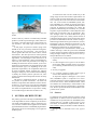
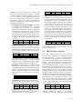
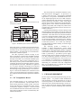
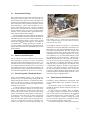
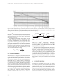
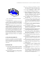
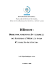
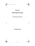
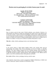
AN EMBEDDED SYSTEM FOR SMALL-SCALED AUTONOMOUS
VEHICLES
David Vissière and Nicolas Petit
Délégation Générale pour l’Armement, France
École Nationale Supérieure des Mines de Paris, France
[email protected], [email protected]
Keywords:
Embedded systems, autonomous vehicles, UAVs.
Abstract:
We consider the problem of designing a modular real-time embedded system for control applications with
unmanned vehicles. We propose a simple and low-cost solution. Its computational power can be easily
improved, depending on application requirements. To illustrate its performance, we report the implementation
of a 75 Hz Extended Kalman Filter used for state estimation on a small-scaled helicopter.
1
INTRODUCTION
In this paper, we present some of our research effort in
a current program aiming at proposing control strategies and a control architecture for a group of heterogeneous autonomous vehicles.
To conduct this research, we designed a versatile
and simple real time embedded system, which can be
easily used as real time guidance and navigation system on various platforms. Our work focuses on heterogenous vehicles, including small-scaled (typically
less than 2 m wide) Vertical Take-Off and Landing
aerial vehicles (VTOL as in (Castillo et al., 2005)) or
fixed wing aircraft, and ground vehicles with tank like
dynamics (as in (Morin and Samson, 2006; Vissière
et al., 2007)). In the future, these vehicles will be
asked to act cooperatively on the battlefield as pictured in Figure 1 (see also (Kaminer et al., 2004;
Olfati-Saber, 2006) for other scenarios).
In practice, the aerial vehicles represent the most
challenging applications in terms of navigation and
guidance. The main reason for this, is that these vehicles can not easily go into any safe mode, as opposed to the ground vehicles which are, in comparison, slower and simpler. While it was proven that,
with lowered performance expectations, it is possible to stabilize a fixed-wing Unmanned Air Vehicles
(UAV) by directly closing the loop with signals from
well-chosen sensors (e.g. in (Lee et al., 2003), the
authors propose a solution to automatically control a
fixed-wing UAV using only a single-antenna GPS receiver), it is considered by the vast majority of the
UAV community that navigation systems require data
fusion (Cheng et al., 2006). In facts, each sensor
technology has its own flaws (among which are drift,
noises, and possibly low resolution or low update frequency). Yet, large factors of accuracy can be gained
by reconciliating their data.
Example of on-board data fusion applications are
ubiquitous among autonomous vehicle control experiments. Reconciliating GPS and Inertial Measurement
Unit (IMU) measurements is a classic case-study.
In (Xiaokui and Jianping, 2002), results of data fusion
from a BeeLine GPS receiver from NovatelTM and a
miniaturized IMU are presented. In (Cremean et al.,
2005), high-speed data fusion systems have been developed in view of the DARPA Grand Challenge.
In this later experiment, several technological
breakthroughs are presented using a high-end and
powerful computer architecture. Software components communicate in a machine-independent fashion
through a module management system.
Our experiments can not use such a high end
setup, because the typical payload of our aerial vehicles does not exceed 5 kg.
Much smaller and lower-weighting systems can
be considered though. In (Jung and Tsiotras, 2007),
an embedded system is proposed which does not
incorporate any powerful calculation board. A
simple Rabbit Semiconductor RCM-3400TM microcontroller is used to perform complementary filtering
data fusion using a limited computational power. In
the same spirit, in (Jung et al., 2005), a low-cost testbed for UAVs is presented. It is reported that the
main advantage of designing such an autopilot from
157
ICINCO 2008 - International Conference on Informatics in Control, Automation and Robotics
Figure 1: Cooperative autonomous vehicles in a future battlefield.
scratch is that, by contrast to commercially available
products (Cloud Cap Technologies, 2004; Micro Pilot, 2004), it provides full access to the internal control structures. We totally agree with this point of
view.
In this paper, we present a solution lying in the
middle of the two previously mentioned categories.
Our system uses two processors. One processor is
used to gather data from the sensors and to control
the actuators. The other processor is used to perform
the data fusion calculations (and possibly the control
algorithms). The advantages of this structure are as
follows: i) task scheduling is easily programmed, because only one of the two processors is in charge of
handling the numerous devices and I/O; ii) the computations are performed as one single thread on a dedicated board (PC type); iii) depending on the computational requirements, the computation board can
be easily upgraded without requiring any software
changes or rising any concern about task scheduling;
iv) finally, the overall system is quite low-cost, since
it relies on off-the-shelf components and can be easily
maintained.
The paper is organized as follows. In Section 2,
we present our system architecture. We detail our
hardware components and comment on their choices.
In Section 3, we present as a test-case the embedding
of our system into a small-scaled helicopter. Numerous details of implementation are provided. Finally,
we conclude and give directions of future work.
A second issue that was also raised early in the
design stage was that the real-time requirements of a
control system for such small UAVs are very strong.
This is mostly due to the short time horizons instabilities. Yet, in the context of embedded systems, realtime scheduling of a number of sensing and computation tasks is known to be a difficult problem. More
precisely, as exposed in (Caccamo et al., 2005), the
problem of determining the feasibility of a periodic
sequence of prioritized tasks is often (NP)-hard. Sufficient, but not necessary tests are pessimistic. Popular strategies such as the Rate-Monotonic policy
(see again (Caccamo et al., 2005)), which consists of
putting the highest priority on the shortest task can be
proven to be unfeasible is the CPU load is too large1.
While being troublesome on ground vehicles, such infeasibilities (and the induced inconsistencies in the
embedded calculations) would represent a cause of
potential major failure for our aerial platforms.
Keeping these two considerations in mind, we decided to develop a robust two-processors embedded
system, running two distinct softwares and communicating through a simple two-ways protocol. The system specifications are as follows.
1. It performs the sensing and calculation tasks separately.
2. It is fast enough to run a typical 15 to 30 dimensional states EKF algorithm with a low latency
(to eventually produce satisfactory closed-loop results).
3. Itis easy to upgrade.
4. It is versatile enough to handle various type of
sensors and communication protocols.
As exposed in Figure 2 and Figure 3, this (modular) embedded system is composed of a microcontroller, which is in charge of gathering information
from all the sensors, and a calculation board. These
two elements are connected by a serial interface. The
micro-controller also has a downlink to a ground station. We now present the details of the hardware components of our system.
2.1 Sensors
2
SYSTEM ARCHITECTURE
Our primary goal was to develop an embedded system
to test algorithms of various complexity on-board various small-scaled platforms. Early in the design process, one first constraint which appeared to us was the
payload limitations of the considered flying machines.
This lead us to focus on designing a low weight embedded system.
158
Considering both ground and aerial vehicles control
applications, we listed a series of useful sensors that
needed to be incorporated into our embedded system.
Among these are: an IMU, a GPS receiver, a pressure sensor, an anemometer, magnetometers, and various switches. Other possibilities include odometers,
1 the
mately.
upper limit on admissible load is 69%, approxi-
AN EMBEDDED SYSTEM FOR SMALL-SCALED AUTONOMOUS VEHICLES
LADARs (as used in (Cremean et al., 2005)), and
sonars (as used in (Vissière et al., 2007)), or cameras
(as used in (Hamel and Mahony, 2007)). In the context of our study, we only considered low-cost sensors. We now detail these. In each case, we specify
the weight (in g), the cost (in USD), the dimensions
(in mm), the update rate (f in Hz), and the protocol of
communication (Comm.).
• Inertial Measurement Unit (IMU). Our IMU
is a 3DM-GX1 from MicrostrainTM. It contains
three angular rate gyroscopes, three orthogonal
single-axis magnetometers, and three single-axis
accelerometers, along with 16 bits A/D converters and a micro-controller. This IMU can deliver
different messages, ranging from raw-data, to reconciliated measurements. In our setup, we ask
the IMU to deliver only calibrated sensors data at
a 75Hz rate.
Weight
30
Cost
1450
Size
39,54,18
f
75
Comm.
RS232
• Global Positioning System (GPS). Our GPS is
a TIM-LS from µbloxTM. Through a proprietary
binary protocol, it provides position and velocity
information at a 4Hz rate. Position error is 2.5 m
(Circular Error Probability CEP) and velocity error is 2 m CEP.
Weight
23
Cost
100
Size
32,47,9.5
f
4
Comm.
RS232
The GPS receiver is not very tolerant against
power supply voltage ripples. These can be kept
below the 50 mV requirements thanks to a dedicated power supply regulator from TRACOTM .
• Barometer. Our barometer is the MS-5534 from
IntersemaTM. Using a SPI-type protocol, it gives
calibrated digital pressure and temperature information. This device requires a 3 V power supply
which is obtained through a fast response diode
from the main 5 V power supply of the microcontroller.
Weight
2
Cost
14
Size
5,4,2
f
20
Comm.
SPI
• Anemometer. A PXLA sensor from ASensTecTM
delivers a differential pressure analog signal,
which can be read through a 10 bit A/D converter.
Weight
10
Cost
25
Size
11,8,12
f
75
Comm.
Analog
• Magnetometer. We use a HMR2300 three axis
magnetometer from HoneywellTM. Its range is ±
2 gauss and it has a 70 µgauss resolution.
Weight
28
Cost
230
Size
75,30,20
f
154
Comm.
RS232
• Take-off and Landing Detector. Being able to
detect take-off and landing instants is necessary to
properly initialize data fusion algorithms. In details, detection of the corresponding switches in
the dynamics defines when the controls actually
have an effect on the system. This is not the case
when an UAV is on the ground. This detection
is performed with on-off switches which can be
located, e.g., on the landing gear. They deliver a
logic signal which can be readily interpreted. To
prevent electric arcs which might cause trouble to
the connected micro-controller, we added a specific interfacing circuit. This switches can also be
replaced by active switches which can be used to
activate various devices such as digital cameras,
or parachutes.
Weight
10
Cost
6
Size
25,10,5
f
75
Comm.
Boolean
Our system is data-driven by the IMU. The main
reason behind this choice is that the IMU is considered as a critical sensor.
2.2 MPC555 Micro-controller
The micro-controller which serves as an interface
for the sensors and actuators is a MPC555 Power
PC from MotorolaTM. It runs a specific software
we developed using the PhytecTM development kit.
The reason for choosing this micro-controller are as
follows. This device provides a double precision
floating-point unit (64 bit) which is convenient for potential embedded algorithms (even if we do not use
this possibility here since all computations are performed on the calculation board), it has a relatively
fast 40 MHz clock, it has 32 bit architecture and
448Kbyte of Flash memory and 4 MBytes of RAM.
Most importantly, among the family of 32 bits kits,
the MPC555 has substantial computational capabilities and a large number of versatile and programmable
Input/Output ports. In particular, we make an extensive use of its TPUs (Time Process Units), UARTs,
A/D converters, SPIs, MPIOs (Modular I/O system)
(see (Motorola, 2000)). Finally, it is small (credit card
format) and has a low weight.
Weight
25
Cost
450
Size
72,57,8
f
all
Comm.
all
No operating system is used on the microcontroller. Rather the MPC555 runs a specific
interrupts-driven software written in C. Information
159
ICINCO 2008 - International Conference on Informatics in Control, Automation and Robotics
Vehicle
actuators
Sensors
Computation
Board
Power PC
Ground
station
Remote
Control
Figure 2: Sensors and computation board connections to the
central micro-controller.
Computation Board
+12V
+3V
IMU
TPU
QSCI1
GPS
TPU
main.c
BAROMETER
QSPI
PITOT
QADC
COMPASS
SCI2
VEHICLE
MIOS
MPWM
TPU
MDASM
DATALINK
Ground
Station
Remote
Control
T/L interrupt
actuators
SWITCH
Receiver
+5V
Figure 3: Embedded system internal connections.
from each sensors is transferred using a dedicated interrupt handler routine. Each external source or group
of sources has its own interrupt level which avoids potential conflicts. Each data link is associated with a
checksum to validate reception.
The data acquisition software running on the
micro-controller is event-driven by the IMU messages
which periodically sends 31 bytes of data. Once the
message of the IMU is received and validated by the
micro-controller, others sensors information are either directly read or picked in data buffers which are
constantly fed with serial messages from the sensors
through hardware interrupts. Information is gathered
in a 116 bytes message containing all the onboard
measurements. This message is sent to the calculation
board through a high-speed serial port. Once the message is received and validated, the calculation board
carries out one navigation loop consisting of a prediction equation and an estimation equation of a Kalman
filter.
2.3 PC Computation Board
The computing board is a PC running the Knoppix 3.8.1 Linux distribution. The PC board was selected among numerous models (mostly mini-ITX,
and PC104) based on computational power, energy
consumption, toughness, and price. A fan-less board
was considered as the most relevant choice, due to the
often observed failures of fans in mechanically disturbed environments.
160
The chosen fan-less calculation board has a standard mini-ITX PC architecture. Its processor is a
1.2Ghz C7-M from VIATM designed for embedded
applications. It can perform 1500 MIPS and has classic PC Input/Output ports such as a UART serial port
(used as main data link with the micro-controller), an
ethernet board (not used here), a VGA screen output
(which can be used to monitor the system during debugging phases of the software and hardware development), a keyboard, and 4 USB ports (which can be
considered for plugging future devices such has controllable cameras).
Experimental preliminary tests have shown us that
multi-threading (one thread for message decoding and
one thread for the main algorithm) presents two major
drawbacks: some data can be lost, and the calculation
cycle may end unexpectedly (slightly) late. For this
reason, we decided to write our own UART driver using an interrupt handler in the kernel space. Further,
we de-activated all hardware interruptions associated
to unnecessary devices. As a result, only interrupts
from the UART are enabled. Finally, we used a single
computation thread.
The operating system is installed on a
bootable 1 Gbyte Disk-On-Chip system which
prevents all possible mechanical failure associated
to hard-drives. This flash memory device is directly
connected to the IDE port of the mother-board. The
board is powered by a pico-PSUTM power supply
which provides various voltages ranging from 5V to
18V. The computation software are written in C and
can be either be updated directly on the board via a
ssh connection, or transferred, in a compiled form,
from a remote PC. Custom scripts for compiling and
distributing our executable code and configuration
files are an efficient way to upgrade the software
during development and testing.
Weight
800
3
Cost
350
Size
170,180,40
f
1.5e6
Comm.
RS232
FIELD EXPERIMENT
We now report some field experiment using our embedded system. To perform model identification
tasks and design a real-time state observer in view of
closed-loop control, we decided to load our embedded system into a small-scaled helicopter. In this section, we expose this work, and give numerous details
about solutions to specific interfacing and vibrational
issues.
AN EMBEDDED SYSTEM FOR SMALL-SCALED AUTONOMOUS VEHICLES
3.1 Experimental Setup
We conducted all the experiments with the help of a
human pilot which could, at any time remotely connect the inputs of the actuators of the helicopter to the
outputs of our embedded system or directly to the outputs of the radio receiver (and thus take direct control
of the helicopter). This is achieved thanks to a “remotely controlled switch board” which we designed.
This switch is actuated from our GraupnerTM MC24
remote controller using one of the 12 available radio
channels. This system provides a rapid transition between manual and autonomous flight.
During all flights, the pilot could see images from
an on-board camera and read measurements from the
embedded system received for the down datalink. A
convenient Head-Up display system on the ground
station was designed for that purpose. Our data link
is a MaxStreamTM module operating at 2.4 GHz. It
provides a RS232 serial data link at 9600 baud sending the information from the embedded system to the
ground station.
Weight
250
Cost
230
Size
40,68,9
f
30
Comm.
RS232
3.2 Small-scaled Helicopter
We use a Benzin acrobatic helicopter from VarioTM,
with GraupnerTM electronics (C4441 servomotors
which have high speed and high torque (8.5 Nm), a 16
channels receiver, and a yaw hobby gyroscope). It is a
very reliable helicopter platform (we never observed
any mechanical issue over mode than 100 flights). Its
payload capacity (4Kg) is large enough for numerous
reconnaissance applications. Its rotor is 1.9 m wide.
3.3 Interfacing and Vibrational Issues
Wiring the embedded system to the existing helicopter circuitry was achieved using some specific additional boards and connectors. To measure the pilot’s
orders in real-time, we used a 6 channels voltage follower circuit. Numerous LEDs were added to check
the status of our system.
A central problem observed on-board helicopters
is the 25 Hz vibrations induced by the main rotor
blades. These vibrations generate a large amount of
noise on the inertial sensors. In practice, these noises
totally overwhelm the useful signals. Fortunately, it
is possible to solve this issue by using well-chosen
noise dampers. On our helicopter, we decided that
the micro-controller and the sensors would all be located on a board which would be physically connected to the frame of the helicopter through four
Figure 4: Our embedded system fitted into the (custombuilt) landing gear of a small-scaled Vario Benzin helicopter. Springs and dampers are used to filter out vibrations
from the main rotor blades.
spring-damper systems (see Figure 4). Experiments
conducted on a vibrating table have shown that it was
advantageous to keep the embedded system as compact and as rigid as possible. The total weight of the
subsystem is about 600 g. We decided to attach some
of the batteries to it to bring the weight close to 1.8 kg.
This enabled us to use off-the-shelf dampers yielding appropriate cut-off frequencies. MV801-5CC
dampers from PaulstraTM were chosen for their ability to work with low masses vibrating at low frequencies. With these, we obtained a satisfactory vibration
damping, with a cut-off frequency around 9 Hz. This
is represented in Figure 5. Further, resonant frequencies due to the engine frequency (around 160 Hz),
the tail rotor frequency (around 115 Hz), and the tail
boom were removed using a digital notch filter. The
presented solution attenuates high frequency vibration inputs down to negligible levels.
3.4 Experimental Identification
Preliminary model identification experiments need
to be conducted before state estimation can be performed.
In particular, using our embedded system, we
studied the actuators transfer functions and the yaw
rate gyroscope.
In some works (see (Mettler, 2003) or (Mettler
et al., 2000)), actuators (servomotors) are considered
as first order systems with dead band. We identified
such transfer functions for various GraupnerTM and
FutabaTM servomotors. Results of various tip-in and
tip-out in reference signals were recorded to compute
the time constant of the first order model.
On board our helicopter, a hobby gyroscope from
161
ICINCO 2008 - International Conference on Informatics in Control, Automation and Robotics
Figure 5: Bode diagram showing the resonance peak and the cut-off frequency of the mechanical structure equiped with the
sensors, the micro-controller, and the spring-dampers suspension. The various plots are obtained on varying locations on the
vibrating structure and show a good spatial uniformity of the vibration damping.
GraupnerTM is used to help the human pilot keeping
the yaw rate as small as possible. Pilot orders are
transferred from the R/C receiver to the tail actuator
through this gyroscope.
To validate simple models of this transfer, we put
our IMU under this gyroscope to measure the angular velocity. Simultaneously, we connected the gyroscope and recorded the gyroscope signals sent to the
tail actuator. Surprisingly, it was discovered that the
gyroscope feedback behaves as a 2 Hz low-pass filter
on the pilot orders, and directly transmits the opposite
of the received angular rate, without filtering it. This
can be summarized under the form
δgyro = Nr rm +
δ pilot
1 + τgyros
3.5 State Estimation
The helicopter is a 6 degrees of freedom mechanical
system with high bandwidth dynamic. Reconstructing the full state of this system from low-cost sensors
only is quite a challenge. We use an Extended Kalman
Filter (EKF, see e.g. (Simon, 2005)) to estimate the
state of this system. In practice, the state of our EKF
is composed of 23 variables including configuration
states (13 variables using quaternions instead of Euler
angles), and the aerodynamic and external forces and
torques (10 variables including the harmonic expansion of the flapping phenomena as exposed in (Mettler
et al., 2001)). We used equally valued tuning parameters for the 3 axis. These are chosen to capture fast
dynamics (statistics data are σacceleration = 8 m.s−2 ,
162
Receive data
State Estimation
Send Data
Figure 6: Succession of steps of data transfer and computation.
and σtorque = 4 rad.s−2 , respectively). Classically,
discrete-time updates are implemented. As already
discussed, updates are synchronized with the 75Hz
measurements from the IMU.
The succession of tasks performed by the computation board of our embedded system is described in
Figure 6. As can be seen, it is necessary, due to a reception time being superior to the available time between two calculation cycles to simultaneously read
or send data and perform computations. Some experimental results are presented in Figure 7. Position
estimates around hovering are reported. In practice,
they appear to be in great accordance with recorded
videos.
4
CONCLUSIONS
Designing an embedded system which can qualify
as a control system for various small-scaled air and
ground vehicles is the subject of the research project
presented in this paper. The embedded system we
propose here has some interesting features. It is simple, low cost and, most of all, easy to upgrade. Its two
processors architecture can incorporate various new
AN EMBEDDED SYSTEM FOR SMALL-SCALED AUTONOMOUS VEHICLES
2
z(m)
1
0
−1
4
2
0
2
−2
y(m)
0
−4
−2
x(m)
Figure 7: Position estimates during a hovering flight.
processors and sensors.
In our laboratory, this embedded system has been
successfully used on a fixed wing aircraft (Rascal 110), a small-scaled helicopter (VarioTM Benzin
trainer), and ground vehicles (Pioneer 4 from Mobile
RobotsTM ).
Further developments focus on giving more autonomy, including path planning algorithm, following (Kogan and Murray, 2006; Murray et al., 2003), to
respond to high-levels orders from a remote user. We
will surely need more computational power, which
can be obtained by simply upgrading the computational board. In parallel, we develop a new aerial vehicle for urban area applications. For this last project
we consider using other sensors. In particular, for
obstacle avoidance and navigation, we will connect
LADARS, and ultrasonic sensors to our embedded
system.
ACKNOWLEDGEMENTS
The authors are indebted to the numerous students,
technicians and engineers who have been collaborating to the development of the presented technology
and have brought their support during the conducted
experiments.
REFERENCES
Caccamo, M., Baker, T., Burns, A., Buttazzo, G., and Sha,
L. (2005). Real-time scheduling for embedded systems. In Hristu-Varsakelis, D. and Levine, W. S., editors, Handbook of networked and embedded control
systems. Birkhäuser.
Castillo, P., Lozano, R., and Dzul, A. E. (2005). Modelling
and control of mini-flying machines. Advances in industrial control. Springer.
Cheng, J., Lu, Y., Thomas, E. R., and Farrell, J. A. (2006).
Data fusion via Kalman filter: GPS and INS. In Ge,
S. S. and Lewis, F. L., editors, Autonomous mobile
robots, Control engineering series. Taylor and Francis.
Cloud
Cap
Technologies
(2004).
http://
www.cloudcaptech.com. Hood River, OR, USA.
Cremean, L. B., Foote, T. B., Gillula, J. H., Hines, G. H.,
Kogan, D., Kriechbaum, K. L., Lamb, J. C., Leibs, J.,
Lindzey, L., Rasmussen, C. E., Stewart, A. D., Burdick, J. W., and Murray, R. M. (2005). Alice: An
information-rich autonomous vehicle for high-speed
desert navigation. Journal of Field Robotics, (9).
Hamel, T. and Mahony, R. (2007). Image based visual
servo-control for a class of aerial robotic systems.
43(11):1975–1983.
Jung, D., Levy, E. J., Zhou, D., Fink, R., Moshe, J., Earl,
A., and Tsiotras, P. (2005). Design and development
of a low-cost test-bed for undergraduate education in
UAVs. In Proc. of the 44th IEEE Conf. on Decision
and Control, and the European Control Conference
2005.
Jung, D. and Tsiotras, P. (2007). Inertial attitude and position reference system development for a small UAV.
In AIAA Infotech at Aerospace.
Kaminer, I., Yakimenko, O., Dobrokhodov, V., Lizaraga,
M., and Pascoal, A. (2004). Cooperative control of
small uavs for naval applications. In Proc. of the 43rd
IEEE Conf. on Decision and Control.
Kogan, D. and Murray, R. M. (2006). Optimization-based
navigation for the DARPA Grand Challenge. In Proc.
of the 45th IEEE Conf. on Decision and Control.
Lee, S., Lee, T., Park, S., and Kee, C. (2003). Flight test results of UAV automatic control using a single-antenna
GPS receiver. In AIAA Guidance, Navigation, and
Control Conference and Exhibit.
Mettler, B. (2003). Identification Modeling and Characteristics of Miniature Rotorcraft. Boston : Kluwer Academic Publishers.
Mettler, B., Tischler, M. B., and Kanade, T. (2000). System
identification of a model-scale helicopter. Technical
Report CMU-RI-TR-00-03, Carnegie Mellon University.
Mettler, B., Tischler, M. B., and Kanade, T. (2001). System
identification modeling of a small-scale unmanned helicopter. Journal of the American Helicopter Society.
Micro Pilot (2004). http://www.micropilot.com. Stony
Mountain, Canada.
Morin, P. and Samson, C. (2006). Trajectory tracking
for nonholonomic vehicles. In Kozlowski, K., editor, Robot Motion Control: Recent Developments.
Springer.
Motorola (2000). MPC555 / MPC556 user’s manual. User’s
manual, Motorola.
Murray, R. M., Hauser, J., Jadbabaie, A., Milam, M. B., Petit, N., Dunbar, W. B., and Franz, R. (2003). Online
control customization via optimization-based control.
In Samad, T. and Balas, G., editors, Software-Enabled
Control, Information technology for dynamical systems, pages 149–174. Wiley-Interscience.
163
ICINCO 2008 - International Conference on Informatics in Control, Automation and Robotics
Olfati-Saber, R. (2006). Flocking for multi-agent dynamic
systems: Algorithms and theory. IEEE Trans. Automat. Control, 51(3):401–420.
Simon, D. (2005). Optimal state estimation. Wiley.
Vissière, D., Chang, D. E., and Petit, N. (2007). Experiments of trajectory generation and obstacle avoidance
for a UGV. In Proc. of the 2007 American Control
Conference.
Xiaokui, Y. and Jianping, Y. (2002). Study on lowcost GPS/DMU integrated navigation system. In
AIAA/AAS Astrodynamics Specialist Conference and
Exhibit.
164