1
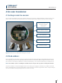
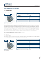
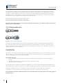
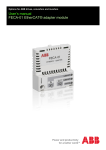
CANopen®
MANUAL / USERS GUIDE FOR THE 600 SERIES
Leine & Linde AB
T +46-(0)152-265 00
F +46-(0)152-265 05
[email protected]
www.leinelinde.com
Publication date: 2012-06-20
CANopen®
USER MANUAL
www.leinelinde.com
Contents
List of tables
4
List of figures
4
1 GENERAL INFORMATION
5
1.1 ABSOLUTE ENCODERS
1.2 CANOPEN® TECHNOLOGY
1.3 ABOUT LEINE & LINDE AB
1.3.1 Technical and commercial support
1.3.2 Certification of CANopen® products
1.4 REFERENCES
1.5 ABBREVIATIONS
5
5
5
6
6
6
6
2 ENCODER INSTALLATION
7
2.1 SETTINGS INSIDE THE ENCODER
2.2 NODE ADDRESS
2.3 BUS TERMINATION
2.4 BAUD RATE SWITCH
2.5 CONNECTING THE ENCODER
2.5.1 Power supply
2.5.2 BUS lines
2.5.3 Shielding philosophy
2.6 EDS FILE
2.7 PARAMETERIZATION
2.8 LED INDICATION
2.8.1 Module LED
2.8.2 Status LED
7
7
8
8
9
9
9
10
10
11
11
11
12
3 PROFILE OVERVIEW
13
4 ENCODER FUNCTIONALITY
14
4.1 BASIC ENCODER FUNCTIONALITY
4.2 DEFAULT IDENTIFIERS
4.3 BOOT-UP MESSAGE
4.4 OPERATING PARAMETERS
4.5 SCALING FUNCTION
4.5.1 Overview
4.5.2 Scaling formulas
4.6 PRESET VALUE
4.6.1 Overview
4.6.2 Preset formula
4.7 ZERO-SET
4.8 VELOCITY AND ACCELERATION
4.9 LSS, LAYER SETTING SERVICES
4.10 PDO MAPPING
4.10.1 PDO configuration
4.10.2 PDO configuration example
4.11 HEARTBEAT
4.12 IRT MODE
14
14
15
15
16
16
17
17
17
18
18
18
18
20
20
21
21
22
3
CANopen®
USER MANUAL
www.leinelinde.com
4.13 ENCODER DIAGNOSTICS
4.13.1 Operating status
4.13.2 Alarms and warnings
5 MANUFACTURER SPECIFIC OBJECTS
5.1 OBJECT 0x5003h, SPEED TYPE
5.2 OBJECT 0x5A03h, SERIAL NUMBER
22
22
23
24
24
24
6 ENCODER CONFIGURATION EXAMPLE
25
7 CERTIFICATE
26
8 REVISION HISTORY
27
List of tables
Table 1 Termination switch settings
Table 2 Baud rate switch settings
Table 3 Pinning M12 power supply connector
Table 4 Pinning bus in/out- lines M12 version
Table 5 Module LED indication
Table 6 Status LED indication
Table 7 CANopen® identifier
Table 8 Broadcast objects
Table 9 Peer-to-Peer objects
Table 10 Operating parameters
Table 11 Singleturn scaling parameter format
Table 12 Multiturn scaling parameter format
Table 13 Preset value format
Table 14 Objects available for PDO-mapping
Table 15 PDO-mapping parameter
Table 16 PDO-mapping example
Table 17 PDO-mapping example, output data
Table 18 PDO-mapping example, save to EEPROM
Table 19 Operating parameters (object 0x6000h)
Table 20 Alarms (object 0x6506h/0x6505h) and Warnings (object 0x6504h/0x6503h)
Table 21 Speed resolution setting
Table 22 Accuracy of speed measurement
Table 23 SDO request message
Table 24 NMT “start remote node” message
Table 25 Revision history
8
8
9
9
11
12
14
14
15
15
16
16
17
20
20
21
21
21
22
23
24
24
25
25
27
List of figures
Figure 1 PCB-view of a cable gland CANopen® encoder
Figure 2 Orientation of M12 power supply connector
Figure 3 Orientation of M12 bus connectors
Figure 4 Cable assembling principal
Figure 5 Basic encoder functionality
Leine & Linde AB claims copyright on this documentation. This documentation may not be modified,
extended or passed onto to a third party and/or copied without written approval from Leine & Linde AB.
Specifications and content in this document are subject to change without prior notice due to our
continuous efforts to improve the functionality and performance of our products.
4
7
9
9
10
14
CANopen®
USER MANUAL
www.leinelinde.com
1 General information
1.1 Absolute Encoders
With an absolute encoder each angular position is assigned a coded position value generated by a code disc
equipped with several parallel fine graduations tracks which are scanned individually. On singleturn encoders,
i.e. an encoder producing absolute positions within one revolution, the absolute position information repeats
itself with every revolution. A multiturn encoder can also distinguish between revolutions. The numbers of
unique revolutions is determined by the resolution of the multiturn scanning and repeats itself after the total
resolution is reached.
1.2 CANopen® technology
The CANopen® communication profile is based on the CAN Application Layer (CAL) specification from
the CiA® (CAN in Automation). CANopen® is regarded as a robust field bus with highly flexible configuration
possibilities. It is used in many various applications all based on different application profiles.
CANopen® comprises a concept to configure and communicate real-time data using both synchronous
and asynchronous messages. Four types of message (objects) are distinguished:
1. Administrative messages (Layer Management,
Network Management and Identifier Distribution Messages)
2. Service Data Messages (SDO)
3. Process Data Messages (PDO)
4. Pre-defined Messages (Synchronization-, Time-stamp-, Emergency Messages)
For further information please view the CANopen® specification.
1.3 About Leine & Linde AB
For more than 40 years the Swedish based company Leine & Linde has concentrated on one thing – development
and manufacturing of advanced encoders that meet the most rigorous demands. That is why a wide selection
of incremental and absolute encoders with obvious concentration on robust products and quality down to the
last detail can be offered. Leine & Linde encoders provide the utmost in reliability year after year, in working
conditions where vibration, dirt, cold and other harsh environments are common.
Leine & Linde can meet very specific individual customer demands. The encoders are easily adapted, due to a
modular design, to the customer’s exact need with respect to resolution, electrical connections and interfaces,
casings, etc. That is due to the fact that tomorrow’s technology already is used today in Leine & Linde ’s product
lines. Leine & Linde concentrate on advanced development of intelligent encoders with integrated ASICs, new
special features and with adaptations to different fieldbus systems such as CANopen®. This enables us to meet
the need for increasingly effective and dependable machines and automation to an even higher degree.
5
CANopen®
USER MANUAL
www.leinelinde.com
1.3.1 Technical and commercial support
Leine & Linde are represented by subsidiaries in many countries around the world. In addition, there are many
services agencies and distributors located worldwide ready to reply to commercial enquires or technical support.
For more contact information, please visit our web site or contact Leine & Linde in Strängnäs, Sweden.
Leine &Linde AB
Box 8
SE-645 21 Strängnäs, Sweden
Tel: +46-(0)152-265 00
Fax: +46-(0)152-265 05
E-mail: [email protected]
Web: www.leinelinde.com
1.3.2 Certification of CANopen® products
In order to achieve interoperability between vendors and appropriate device functionality CANopen® products
developed and manufactured by Leine & Linde AB has been verified by external bodies. Leine &Linde AB are
proud to announce that CANopen® enabled products successfully passed a certification process performed by
CiA®, CAN in Automation. A copy of the certificate is attached in this manual.
1.4 References
http://www.can-cia.org
CAN Application Layer, DS 201 …207
CAL Based Communication Profile, DS 301
Device Profile for Encoders, DS 406
CAN Specification Version 2.0 A
CANary CAN controller
CiA®
CiA®
CiA®
Robert Bosch GmbH
Atmel
1.5 Abbreviations
CAN
CiA®
CAL
EDS
DCF
SDO
PDO
TPDO
COB-ID
NMT
IRT
LSS
6
Controller Area Network
CAN in Automation
CAN Application Layer
Electronic Data Sheet
Device Configuration File
Service Data Object
Process Data Object
Transmit PDO
Communication Object Identifier
Network Management
Isochronous Real Time
Layer Setting Services
CANopen®
USER MANUAL
www.leinelinde.com
2 Encoder Installation
2.1 Settings inside the encoder
The encoder node address, baud rate and bus termination must be configured during commissioning of the
device. This is done by removing the back cover and open up the three screws at the rear of the encoder.
Screw terminal for bus
and power supply
connection
Node address switches
Zero-set button
Bus termination on/off
Baud rate switch
Figure 1 PCB-view of a cable gland CANopen® encoder
2.2 Node address
The node address of the device can be set using two decimal rotary switches located inside the back cover.
The weighting, x10 and x1 are specified beside the switches. Permissible address range is between 1 and 98
(99 is used for accessing LSS). Address 0 is used for broadcasting, i.e. the master broadcasting to multiple slaves.
Note: Each address used in a CANopen® network must be unique and may not be used by other devices.
The device address is read and adopted when the encoder power supply is switched on (or NMT command
Reset_Communication or Reset_Node). Either of these actions is therefore required in order to adopt changes
done to the address settings (except when LSS service is used).
7
CANopen®
USER MANUAL
www.leinelinde.com
2.3 Bus termination
In a CANopen® network, all devices are connected in a bus structure. Up to 126 devices (master and/or slaves)
can be connected in one segment. When more devices are needed repeaters should be used to amplify the signals
between segments. An active termination need to be placed in the beginning and end of each bus segment in
order to ensure error-free operation. In case of cable gland encoder such terminators are integrated inside the
back cover and can be activated via the dip switches.
The active termination is only activated when the encoder is powered on. If the device is un-powered the
CAN_H and CAN_L lines are internally terminated by a 121Ω resistor.
Bit 1
Bit 2
Effect
ON
ON
There is a 121 ohm resistor between CAN_H and CAN_L.
ON
OFF
Not a valid setting.
OFF
ON
Not a valid setting.
OFF
OFF
There is no resistor between CAN_H and CAN_L.
Table 1 Termination switch settings
When encoder with M12 connectors is used the termination must be done using a terminating resistor plug. The
terminating resistor plug is available as an accessory from Leine & Linde. The plug is assembled in resemblance to
the M12 cables and both male and female contacts are available in order to enable termination in both ends of the bus.
2.4 Baud rate switch
The communication baud rate can be set using the rotary switch inside the encoder. The baud rate is set
according to table 2 below. If the baud rate switch is set to 9, the baud rate can be set by LSS service.
For more information regarding LSS, see chapter 4.9.
Baudrate
Baudrate switch
10 kbit/s
0
20 kbit/s
1
50 kbit/s
2
125 kbit/s
3
250 kbit/s
4
500 kbit/s
5
800 kbit/s
6
1000 kbit/s
7
400 kbit/s
8
LSS service
9
Table 2 Baud rate switch settings
8
CANopen®
USER MANUAL
www.leinelinde.com
2.5 Connecting the encoder
2.5.1 Power supply
The power supply connection of M12 equipped encoders are constituted by a male A-coded 4 pin M12 connector.
Power supply M12 version
Power supply
Figure 2 Orientation of M12
power supply connector
Function
Pin
+EV (9-36Vdc)
1
Not connected
2
0V
3
Not connected
4
Table 3 Pinning M12 power supply connector
Encoders equipped with cable glands are delivered with a dust protection foil from the factory. The protection
foil needs to be removed prior to installing the cables. The cable gland encoders should always be equipped
with a shielded power supply cable with conductor area between 0,34mm2 to 1.5mm2. Permissible outer cable
diameter is ø8mm to ø10mm. Located inside the back cover are two screw terminals containing the required
power supply terminals marked (+) and (-). In the case were the encoder is the last node in the bus-structure
and only the cable for the Supply and Bus-in is in use, the Bus-out cable gland should be replaced with a M16
filler plug to ensure proper sealing. The M16 filler plug is available as an accessory from Leine & Linde.
The (+) terminal shall be used to connect the +EV-line (9-36Vdc).
The (-) terminal shall be used to connect the 0V-line.
2.5.2 BUS lines
The CANopen® bus line connections of the M12 equipped encoder are constituted by a male A-coded 5 pin M12
connector (bus in), and a female A-coded 5 pin M12 connector (bus out).
Bus in/out- lines M12 version
Bus out
Bus in
Figure 3 Orientation of M12
bus connectors
Function
Pin
CAN shield
1
CAN V+
NC
CAN GND
3
CAN_H
4
CAN_L
5
Table 4 Pinning bus in/out- lines M12 version
9
CANopen®
USER MANUAL
www.leinelinde.com
The cable gland encoders shall be equipped with twisted pair shielded cable in accordance with EN 50170.
The guidelines recommend a conductor area higher than 0,34mm2. Permissible outer cable diameter is ø6mm
to ø8mm. Located inside the back cover are six screw terminals containing the required bus line terminals
marked H, L and G. Cable glands not used, should be replaced with a M16 filler plug to ensure proper sealing.
The M16 filler plug is available as an accessory from Leine & Linde.
The (H) terminal shall be connected to CAN_H line.
The (L) terminal shall be connected to CAN_L line.
The (G) terminal shall be connected to CAN_GND line
Note: The two H and L-terminals are internally connected to each other, i.e. it does not matter to which pair
the bus lines are connected to.
2.5.3 Shielding philosophy
Figure 4 Cable assembling principal
To achieve the highest possible noise immunity and resistance against other EMI related disturbances the
bus and power supply cables shall always be shielded. The screen should be connected to ground on both
ends of the cable. In certain cases compensation current might flow over the screen. Therefore a potential
compensation wire is recommended.
2.6 EDS file
An EDS-file is available for downloading at our homepage, www.leinelinde.se. Due to Leine & Linde ’s constant
drive to support our customer with the latest updates of encoder functionality it is recommended to consult
Leine & Linde representative for the latest releases.
The EDS file describes:
• The communication functionality and objects as defined in the CANopen® communication profile
DS-301.
• The device specific objects as defined in the Encoder Profile DS-406.
• Manufacturer specific objects.
The EDS file serves as a template for different configurations of one device type. A DCF-file is generated from the
EDS-file describing a specific configuration of the device including object values, selected baud rate and module-Id.
CANopen® configuration tools are available to support CANopen® network configuration and device
configuration via the CAN bus. The information about the device is obtained from the EDS-file.
Note: The EDS Installation procedure depends on your configuration tool, please consult your tool supplier if
problems occur.
10
CANopen®
USER MANUAL
www.leinelinde.com
2.7 Parameterization
The parameters are set from the configuration tool when the device is in the Pre-Operational state using the
objects obtained from the EDS-file. The parameters can also be changed during runtime (Operational state),
please be careful as the position data is directly affected by some parameters and will change directly following
such parameter message. Therefore changing the scaling function parameters and the code sequence should
only be used at encoder standstill.
Note: The parameterization procedure depends on your configuration tool, please consult your tool supplier
if problems occur.
2.8 LED indication
In order to determine the status of the encoder two LED’s are visible from the rear end of the encoder. The
module LED indicates status of the module itself. The status LED shows the module status on the bus. The
LED’s can be constantly on, off, blinking and flashing. Blinking means on for 200 mS and off for 200 mS. If the
LED’s is flashing it is on for 200 mS and off for 1000 mS (single flash) or on 200 mS, off 200 mS, on 200 mS and
off 1000 mS (double flash).
2.8.1 Module LED
The module LED is a bicolor LED with functionality as below.
LED
Indication
Off
No power.
Green
OK.
Red
Position error, the encoder is not able to give a correct position value.
3 x Blinking Green, Off,
Zero-set button pushed and position set to zero. After 3 blinks the led
will automatically go back to the previous state.
Blinking red
Faulty switch settings.
Table 5 Module LED indication
11
CANopen®
USER MANUAL
www.leinelinde.com
2.8.2 Status LED
The status LED is a bicolor LED with two functions; one green LED (Run status) and one red LED (Error status).
RUN STATUS (GREEN) LED
Indication
Blinking green
The encoder is NMT state Pre-operational.
Single green flash
The encoder is NMT state Stopped.
Green
The encoder is NMT state Operational.
ERROR STATUS (RED) LED
Indication
Off
No error.
Single red flash
Warning limit reached on Receive error counter or
Transmit error counter.
Double red flash
A guard event or a heartbeat event has occurred.
Red
The encoder is Bus-off.
Flashing red/green
The encoder does not have any Node_ID
Table 6 Status LED indication
When the encoder is on error free communication in operational state both the module and the status LED
should shown green.
12
CANopen®
USER MANUAL
www.leinelinde.com
3 Profile overview
The Encoder Profile defines the functionality of encoders connected to CANopen®.
The operating functions are divided in two device classes:
CLASS 1
The Mandatory class with a basic range of functions that all Encoders must support.
The class 1 encoder can optionally support selected class 2 functions, these functions must
however be implemented according to the profile.
CLASS 2
Where the Encoder must support all class 1 functions and all functions defined in class 2.
The full class 2 functionality includes:
• Absolute position value transfer using either polled, cyclic or sync mode.
• Velocity and acceleration output values
• Change of code sequence
• Preset value settings
• Scaling of the encoder resolution
Advanced diagnostics including:
• Encoder identification
• Operating status
• Operating time
• Alarms and warnings
All programming and diagnostic parameters are accessible through SDO’s.
The output position value from the encoder is presented in binary format.
13
CANopen®
USER MANUAL
www.leinelinde.com
4 Encoder functionality
4.1 Basic encoder functionality
The figure below gives an overview of the basic encoder functions and how the functionality is conducted
within the encoder.
Physical position
Code sequence
Singleturn resolution
Number of distinguishable revolutions
Basic funtion
Absolute position
Scaling function
Measuring units per revolution
Total measuring range in measuring units
Scaling function control/status
Preset function
Preset value
Offset value
Output position value
Figure 5 Basic encoder functionality
4.2 Default identifiers
In order to reduce configuration effort a default identifier allocation scheme is defined for CANopen® devices.
This ID-allocation scheme consists of a functional part, which determines the object priority and a moduleID-part, which is equal to the node number (1 to 127). Broadcasting of non-confirmed services (NMT and SYNC)
is indicated by a module-ID of zero.
In CANopen® the 11 bit identifier is built as follows:
Bit-Nr
10
9
8
7
Function Code
6
5
4
3
2
1
0
Node Number
Table 7 CANopen® identifier
The following broadcast objects with default identifiers are available in the encoder:
Object
Function Code (binary)
Resulting Identifier (COB-ID)
Priority group
NMT
0000
0
0
SYNC
0001
128dec
0
Table 8 Broadcast objects
14
CANopen®
USER MANUAL
www.leinelinde.com
The following Peer-to-Peer objects with default identifiers are available in the encoder:
Object
Function Code (binary)
Resulting Identifier (COB-ID)
Priority group
EMERGENCY
0001
80h + node id
0, 1
PDO1 (tx)
0011
180h + node id
1, 2
PDO2 (tx)
0101
280h + node id
2, 3
SDO (tx)
1011
580h + node id
6
SDO (rx)
1100
600h + node id
6, 7
Node guard
1110
700h + node id
-
Table 9 Peer-to-Peer objects
4.3 Boot-up message
The encoder sends a Boot-up message after power-on and initialization. This message uses the default Node
guard identifier (ID=700h+ node id) and has no data bytes. With this message the user can retrieve the sending
node directly from the used identifier (COB-ID) as it is a function of the node number, see chapter 4.2.
4.4 Operating parameters
Object 0x6000h, operating parameters, controls the functions for Code sequence and Scaling and read position
at Sync.
Bit
Function
Bit = 0
Bit = 1
Class 1
Class 2
0
Code Sequence
CW
CCW
M*
M*
1
N.A.
2
Scaling function control
Disabled
Enabled
O
M
3
N.A.
4 -11
Reserved for further use
12 - 14
Manufacturer specific parameter
N.A.
N.A.
O
O
15
Read position at sync
Disabled
Enabled
-
-
* not for linear encoders ** not for rotary encoders
Table 10 Operating parameters
The code sequence defines whether increasing or decreasing position values are output when the encoder
shaft rotates clockwise or counterclockwise as seen on the shaft. The scaling function control is used for
enabling/disabling the scaling parameters measuring units per revolution (object 0x6001h) and total measuring
range in measuring units (object 0x6002h), see chapter 4.5. If the scaling function bit is set, the scaling parameters will affect the output position value. If the scaling function bit is set to zero, the scaling function is
disabled.
Note: The position value will be affected when the code sequence is changed during operation.
It might be necessary to perform a preset after the code sequence has been changed.
15
CANopen®
USER MANUAL
www.leinelinde.com
4.5 Scaling function
4.5.1 Overview
With the scaling function the encoder internal numerical value is converted in software to change the physical resolution of the Encoder. The parameters ”Measuring units per revolution” (object 0x6001h) and ”Total measuring range in
measuring units” (object 0x6002h) are the scaling parameters set to operation with the scaling function control bit in
object 0x6000h.
Note: Total measuring range in measuring units = Measuring units per revolution x Number of distinguishable
revolutions. When scaling a multiturn encoder the parameter “Measuring units per revolution” must be sent
before the parameter “Total measuring range in measuring units”.
The data type for both scaling parameters is unsigned 32 with a value range from 1 to 232 limited by the encoder
resolution. For a 25 bit multiturn encoder with a singleturn resolution of 13 bits resolution the permissible value
for the ”Measuring units per revolution” is between 1 and 213 (8192). The permissible value for the ”Total measuring
range in measuring units” is between 1 and 225 (33 554 432). To achive the highest permissible value of 225 (33 554
432) for the “Total measuring range in meausuring units” the “Measuring units per revolution” must be set to 213
(8192). The scaling parameters are securely stored in case of voltage breakdown and reloaded at each start-up.
Byte
3
2
1
0
Bit
31 - 24
23 - 16
15 - 8
7 - 0
Data
231 - 224
223 - 216
215 - 28
27 - 20
Object 0x6001h – Measuring units per revolution
Table 11 Singleturn scaling parameter format
Byte
3
2
1
0
Bit
31 - 24
23 - 16
15 - 8
7 - 0
Data
231 - 224
223 - 216
215 - 28
27 - 20
Object 0x6002h – Total measuring range in measuring units
Table 12 Multiturn scaling parameter format
The measuring range is set by the object ”Total measuring range in measuring units”. The encoder has two different operating modes depending on the specified measuring range. If the scaling is binary the encoder enter
operation mode A, Cyclic operation and if the scaling value is non-binary the encoder enters operation mode B,
Non cyclic operation.
A. CYCLIC OPERATION (Binary scaling)
Used when operating with 2X number of turns (2, 4, 8, 16, 32, 64, 128, 256, 512, 1024, 2048 and 4096 number of
turns). If the desired measuring range is equal to the specified singleturn resolution * 2X (where x <= 12) the
encoder operates in endless cyclic operation (0 - max - 0 - max ...). For example: If the position value increases
above the maximum value (measuring range-1) by rotating the encoder beyond the maximum value
the encoder continues from 0.
Example of a cyclic scaling:
Measuring units per revolution = 1000
Measuring range = 32000 (25 = 32 number of turns)
16
CANopen®
USER MANUAL
www.leinelinde.com
B. NON CYCLIC OPERATION
If the measuring range is used to limit the encoder value range to a value not equal to the specified singleturn
resolution * 2x the output position value is limited within the operating range. If the position value increases
or decreases outside the measuring range by rotating the encoder beyond the maximum value (measuring
range-1) or below 0 the encoder outputs the total measuring range value.
4.5.2 Scaling formulas
The scaling function used in the CANopen® encoder is limited to a singleturn resolution within one step. After
downloading new scaling parameters the preset function should be used to set the encoder starting point.
Note: Changing the scaling function parameters should only be used at encoder standstill.
In the following formula a 25 bit multiturn encoder with a singleturn resolution of 13 bits is used as an example.
A=
(singleturn_position x measuring_units_per_revolution)
8192
output_position = (revolution_number x measuring_units_per_revolution) + A
Where: singleturn_position = the Absolute singleturn position value
revolution_number = the Absolute multiturn number
4.6 Preset value
4.6.1 Overview
The preset function (object 0x6003h) supports adaptation of the encoder zero point to the mechanical zero
point of the system. The preset function sets the actual position of the encoder to the preset value. The preset
function is used after the scaling which means that the preset value is given in the current measuring units.
A preset is handled by the encoder in the following way: The encoder reads the current position value and
calculates an offset value from the preset value and the read position value. The position value is shifted with
the calculated offset value. The offset value can be read with object 0x6509h and is securely stored in case of
voltage breakdown and reloaded at each start-up.
Note: The preset function should only be used at encoder standstill.
Byte
3
2
1
0
Bit
31 - 24
23 - 16
15 - 8
7 - 0
Data
231 - 224
223 - 216
215 - 28
27 - 20
Object 0x6003h – Preset Value
Table 13 Preset value format
17
CANopen®
USER MANUAL
www.leinelinde.com
4.6.2 Preset formula
An offset_value is calculated when the encoder receives the preset_value, see setup calculation below.
The offset_value is then used during runtime to shift the current position to get the required output position,
see runtime calculation below.
Note: In the formulas below the current_position is the Absolute position of the encoder
disk after the scaling function. The calculations are made with signed values.
Setup calculation:
offset_value=preset_value_current_value
Note: A previously set offset_value is not included in the current position.
Runtime calculation: output_position=current_position+offset_value
4.7 Zero-set
Zero setting of the encoder can be done two folded. Using the preset (object 0x6003h) and set the preset value
to zero (00 00 00 00h) makes a zero-set of the encoder. Also, if the zero set button is pushed for at least 1 second
the position off the encoder will be set to zero (00 00 00 00h). The module LED will signal: green, off, green, off,
green, off to confirm that the position value is set to zero.
4.8 Velocity and Acceleration
The encoder supports output of both speed (object 0x6030h) and acceleration (object 0x6040h). In order to
maintain accuracy independently of the rotation speed of the encoder various measuring unit can be set.
The speed object is limited to a signed 16-bit value and an optimization of assumed rotation speed of the
shaft with respect to chosen resolution is required in order to avoid data overflow.
Object 0x5003h, speed type, is a manufacturer specific object that sets the update time and resolution (Steps/
second or RPM) of the speed (object 0x6030h) and acceleration (object 0x6040h) value. The speed type object is
described in chapter 5.1.
4.9 LSS, Layer Setting Services
The encoder supports LSS functionality, which is a service to remotely set Node_ID and communication baud
rate. The LSS function is not available when the encoder is in the NMT mode “Operational”. To change the
Node_ID by LSS, both address switches X10 and X1 must be set to 9.
At first start up with the address switches set to 99 the encoder will have a invalid Node_Id. The encoder will
therefore not send a boot up message and will only communicate with LSS messages, all other messages
(like PDOs and SDOs) will be ignored until a valid Node_ID has been set.
If the address switches are set to anything else than 99 at start up, the Node_Id will be set according to the
position of the switches. A reset of the LSS-setting will also be made, which means that once the encoder is
restarted with the address switches set to 99, the encoder will have an invalid Node_Id, as in the first start up.
If the baud rate switch is set to 9, the encoder also enters LSS and the baud rate can be set by LSS. When the
encoder starts with the baud rate switch set to 9 the encoder uses the stored baud rate. Before any baud rate
has been stored the encoder will use 125 Kbit.
If the encoder starts up with the baud rate switch set to anything else than 9, the baud rate will be according to table
2 in chapter 2.4 Baud rate switch. A reset of the LSS-setting will also be made, which means that once the encoder
is restarted with the baud rate switch set to 9, the encoder will use 125 Kbit until any other value has been stored.
18
CANopen®
USER MANUAL
www.leinelinde.com
If both baud rate and Node_Id shall be set by LSS, it is recommended to follow the sequence below:
1) Start with enable LSS in all node on the network for both setting Node_Id and Baud rate. This is done on
the Leine & Linde encoders by setting all three switches (Baud rate, Address X10 and Address X1) to 9.
2) Switch on power supply.
3) Set all Nodes to “LSS Configuration”.
4) Set the new baud rate with “Configure bit timing parameters”.
5) Store the new value with “Store configuration”.
6) Activate the new baud rate with “Activate bit timing parameters”, chose a delay that is long enough so you
have time to change the LSS masters baud rate before the nodes starts to communicate with the new baud
rate.
7) Set all Nodes to “LSS Waiting mode” with “Switch state global”.
8) Set one node at a time to “LSS Configuration”.
a) First use “LSS switch mode selective Vendor ID” with the nodes vendor ID (obj 0x1018h, sub-index 1).
Leine & Linde ´s Vendor ID is “0x00000194h”
b) Then use “LSS switch mode selective Product code” with the nodes product code (obj 0x1018h,
sub-index 2). Leine & Linde product code for the 600 series is “60010” (258h).
c) Then use “LSS switch mode selective Revision number” with the nodes revision number (0x1018h,
sub-index 3). The revision number is written on the encoder label.
For example 11.0 is written on the encoder label. 11.0 => 0x000B0000h where 000B is the major and
0000 is the minor value.
d) Then use “LSS switch mode selective Serial number” with the nodes serial number (0x1018h,
sub-index 4). The serial number of the encoder is written on the encoder label as a numerical value
in decimal form.
Now one (and only one CAN node) is in “LSS Configuration mode”.
9) Set the Node_Id with “Configure Node-ID”.
10) Store the Node_ id with “Store configuration”.
11) Set the node to “LSS Waiting”. The node will now exit LSS and start up with the new Node_id and it
will send a “Boot-up” message.
12) Repeat step 8 to 11 for all nodes.
19
CANopen®
USER MANUAL
www.leinelinde.com
4.10 PDO mapping
Dynamic PDO mapping enable changes of the objects sent in a PDO. The Leine &Linde 600 series
encoder can map three different objects in to the PDO’s. These are:
Name
Object
Sub index
Length
Position
0x6004h
Speed
0x6030h
1
2 byte
Acceleration
0x6040h
1
2 byte
4 byte
Table 14 Objects available for PDO-mapping
The encoder has two transmit PDO, named PDO1 (sent cyclically by Cyclic_timer) and PDO2 (sent when a
SYNC message is received). Both PDO’s are as default mapped to send only position data. Both PDO’s can
independently be change to send any combination and order of the object above.
The structure of the entries of object “Transmit PDO mapping parameter” sub index 1 – 3 is as follows.
Byte MSB
Byte MSB - 1
Object
Byte LSB + 1
Byte LSB
Sub index
Object length (Nr of bits)
Table 15 PDO-mapping parameter
4.10.1 PDO configuration
To change the PDO mapping the encoder must be in NMT mode PRE-OPERATIONAL. The PDO must be set to
“not valid”. This is done by clearing bit 31 (MSB) in sub index 1 “COB-ID used by PDO” in object “Transmit PDO
communication parameters”.
The PDO must be deactivated, set “Transmit PDO mapping parameter” sub index 0 to 0.
To reconfigure the PDO mapping send data of which object, sub index and length of the first object to “Transmit
PDO mapping parameter” sub index 1. Then do the same for the optionally second and third object to “Transmit
PDO mapping parameter” sub index 2 and 3.
The “Transmit PDO mapping parameter” sub index 0 must be set to the number of objects mapped to the PDO (1-3).
The reconfigured PDO mapping must be set to “valid” by setting bit 31 (MSB) in sub index 1 “COB-ID used by
PDO” in object “Transmit PDO communication parameters”. After setting the encoder in NMT mode OPERATIONAL the reconfigured PDO mapping is enabled.
The PDO mapping can be securely stored to EEPROM by using the object 0x1010h “Store parameter Field”
(sub index 1 “All parameters” or sub index 2 “communication parameters”).
20
CANopen®
USER MANUAL
www.leinelinde.com
4.10.2 PDO configuration example
The following chapter shows how to map PDO1 with position and speed (the encoder has address 0x0Fh,
all data in hexadecimal format):
Step
ID
Data
1
0
80 0F
Set the encoder in NMT mode PRE-OPERATIONAL.
2
60F
23 00 18 01 8F 01 00 80
Set PDO1 to not valid, and COB-ID to 0x18Fh
3
60F
2F 00 1A 00 00 00 00 00
Set “Transmit PDO mapping parameter” sub index 0 to 0
(mapping deactivated).
4
60F
23 00 1A 01 20 00 04 60
Map position (object 0x6004h) to the first position in the PDO.
5
60F
23 00 1A 02 10 01 30 60
Map Speed (object 0x6030h) to the second position in the PDO.
6
60F
2F 00 1A 00 02 00 00 00
Set “Transmit PDO mapping parameter” sub index 0 to 2
(The number of object mapped to the PDO).
7
60F
23 00 18 01 8F 01 00 00
Set PDO1 to valid, and COB-ID to 0x18Fh
8
0
01 0F
Set the encoder in NMT mode OPERATIONAL.
Table 16 PDO-mapping example
The mapping of the PDO1 is now finished. The PDO1 message can for example look like:
ID
Data
18F
4E C9 B2 00 53 01
Table 17 PDO-mapping example, output data
Where “4E C9 B2 00” is position data and “53 01” is the speed value.
To save the PDO mapping to EEPROM send:
ID
Data
60F
23 10 10 02 73 61 76 65
Save all communication parameters by sending the ASCII
code for “SAVE” to object 0x1010h, sub index 2.
Table 18 PDO-mapping example, save to EEPROM
4.11 Heartbeat
The Leine & Linde CANopen® encoder can act as a heartbeat producer. The time between two heartbeats is
configured in object “Producer heartbeat time” (0x1017h) and is in the unit milliseconds (1 - 65535). If the
“Producer heartbeat time” (0x1017h) is zero (0) the heartbeat is deactivated.
The object “Producer heartbeat time” (0x1017h) is securely stored in the EEPROM and reloaded at start up.
21
CANopen®
USER MANUAL
www.leinelinde.com
4.12 IRT mode
In order to enhance the real-time characteristics the encoder can operate in IRT, Isochronous Real Time mode.
In normal operating mode the position value is sampled cyclically every 0.5 mS. If the “Read position at sync”
is disabled the PDO2 (send data at sync) uses the last sampled position of the encoder. This adds a non-real
time characteristics to the output position value. In IRT mode, “Read position at sync” is set, the position value
is only sampled when the sync message is received.
When the “Read position at sync” bit is set in the operating parameter (object 0x6000h), the following changes
are made:
• Speed (object 0x6030h) and the acceleration (object 0x6040h) is disabled because cyclic position sampling
is mandatory for calculating these values.
• PDO1 (send data cyclic) is disabled, object 0x1800h sub index 1 bit 31 is set and stored to EEPROM.
• The object “PDO1 transmit” (object 0x1800h) is read only when the “Read position at sync” bit is set.
• The PDO2 (send data at sync) will be set to only send position data and the new PDO2 mapping will be
stored in EEPROM.
• The object “PDO2 tx mapping” (0x1A01h) will be read only if the “Read position at sync” bit is set.
Note: If speed and acceleration values is requested during operation in IRT mode it is recommended to
calculate these values in the master application and use the master clock (sync message) as reference.
Bit
Parameter
0
Code sequence
1
N.A.
2
Scaling function control
3-14
N.A.
15
Read position at sync
Table 19 Operating parameters (object 0x6000h)
4.13 Encoder diagnostics
The encoder diagnostics can be read from objects 0x65xxh. The operating status, alarm and warning diagnostics are described in the following chapters. For complete overview of the diagnostics supported please view the
EDS file.
4.13.1 Operating status
In object 0x6500h the operating status can be read. The function for each bit is in reassembles to the operating
parameters, see chapter 4.4. Bit 2, scaling function control, in operating status is set depending on the setting in
operating parameters in addition the actual scaling values used in the encoder can be read out as diagnostics,
object 0x6501h (singleturn resolution) and object 0x6502h (multiturn resolution).
22
CANopen®
USER MANUAL
www.leinelinde.com
4.13.2 Alarms and warnings
If an internal alarm is detected by the encoder it automatically enters pre-operational state. A COB-ID EMCY
(object 0x1014h) message is sent by the encoder transferring what type of alarm has occurred. To re-enter the
operational state a NMT command has to be sent. The encoder supports the following alarms.
Bit
Supported_alarms/Alarms
Bit
0
Position error
0
1-11
12
E2prom error
13-15
Table 20 Alarms (object 0x6506h/0x6505h)
Supported_warnings/Warnings
1
Light control
2
Watchdog
3-15
Warnings (object 0x6504h/0x6503h)
23
CANopen®
USER MANUAL
www.leinelinde.com
5 Manufacturer specific objects
5.1 Object 0x5003h, Speed type
Object 0x5003h sets the update time and resolution (Steps/second or RPM) of the velocity information.
This object affects both the speed (object 0x6030h) and the acceleration (object 0x6040h).
Speed type
Setting
0
200 mS update time, Steps/S.
1
10 mS update time, Steps/10 mS.
2
100 mS update time, Steps/100 mS.
3
200 mS update time, RPM.
Table 21 Speed resolution setting
The speed object is limited to a signed 16-bit value. In order to avoid data overflow and optimize the accuracy
it is recommended to calculate the optimal speed type setting. Also adopt scaling to the encoder limits the
amount of data avoiding overflow as the speed value calculation is based on the scaled singleturn value.
For example if the rotation of the shaft is faster than 1000 rpm and the speed type are 0, steps/S, a data
overflow will occur. In this case a higher resolution is required, i.e. steps/100ms.
The accuracy of the speed measurement is dependent on the resolution chosen.
The figure in this table should be considered as a guideline.
Speed type
Shaft rotation
0
>100 RPM
1
>1000 RPM
2
>1000 RPM
3
>100 RPM
Table 22 Accuracy of speed measurement
The table shows at from which shaft rotation speed the accuracy of the measured value deviates less than 1%.
General, independent of speed type chosen, the accuracy improves the higher the shaft rotation is.
5.2 Object 0x5A03h, Serial number 2
Object 0x5A03h is a manufacturer specific object were the serial number of the including base encoder can
be read. This object is mainly useful when a gateway solution is used but it is implemented for the integrated
encoders as well to maintain a general approach for the supported objects.
24
CANopen®
USER MANUAL
www.leinelinde.com
6 Encoder configuration example
This example shows a simple setup of the encoder for cyclic transmission of the position value.
1) Set the physical address (Node Number) of the encoder using the address switches, see section
s.2 for further information.
2) Verify that the baud rate of your CANopen® network and the baud rate of the encoder is the same.
See section 2.3 for further information regarding the baud rate setting of the encoder.
3) Power up the encoder.
4) The encoder will send a Boot-up message on the default Node guard identifier
(ID = 700h + encoder address), the message has no data bytes.
5) The next step is to configure the encoder through the SDO message. To set a cyclic transmission of the
position value with 10ms repetition rate, an SDO request message (ID = 600h + encoder address) sent to
the cyclic timer (object 0x6200h) with the data below, is required. The encoder will confirm with the SDO
response message (ID = 508h + encoder address).
Byte 0
Byte 1
Byte 2
Byte 3
Byte 4
Byte 5
Byte 6
Byte 7
0x22
0x00
0x62
0x00
0x0A
0x00
0x00
0x00
Command
Object
Subindex
4 byte Data
Table 23 SDO request message
6) To get the encoder in operation we need to send an NMT “start remote node” message,
ID = 0, two data bytes with the following contents:
Byte 0
Byte 1
0x01
The encoder address (Node Number)
Table 24 NMT “start remote node” message
7) The encoder has now entered the operational state and the position message
(ID = 180h + encoder address) is transferred with a 10ms repetition rate.
If an error occur the encoder will send an emergency message (ID = 80h + encoder address).
25
CANopen®
USER MANUAL
7 Certificate
26
www.leinelinde.com
CANopen®
USER MANUAL
www.leinelinde.com
8 Revision history
Revision
Date
Changes
Rev. 1.0
2012-06-20
First release
Table 25 Revision history
27
+46-(0)152-265 00 www.leinelinde.com
Part no. 634815-01, ver. 1.0
The best encoders are those you never have to think
about. Those that simply do their job – year after year.
Leine & Linde develops and manufactures customised encoder solutions for demanding environments,
advanced measuring systems for accurate feedback
of speed and position.