1
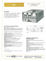
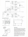
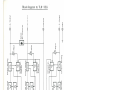
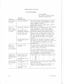
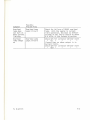
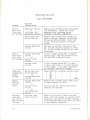
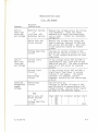
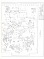
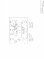
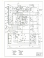
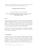
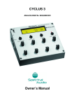
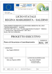
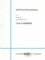
INSTRUCTION MANUAL
ON
STABILIZED
TRIPLE POWER SUPPLY
TLS-3 SERIES
SVSTRON
DONNER
G
M
B
H
INSTRUCTION MANUAL
....
,,,.. tl
......······:.f
············
............
···::···~:···~~···:::
••',,•!~.;..·•
...••'ee•!!!.ttt'!
......
~dlf·'
,.,~~~.•.••••tr,,er,,.,....
~.~..~............
!dt• .......
~.,!i"'r .
.,
AC
MODEL TL8-3 EG and TL8-3 EG OV
STABILIZED TRIPLE POWER SUPPLY
Note :
In case of technical questions or spare part requests please specify
the model and serial-No. of the power supply.
Address:
SYSTRON DONNER GMBH, 8 Munchen 60, BodenseestraBe 113
Telephone: (0811) 87110 21
WARRANTY.
SYSTRON-DONNER instruments are warranted during a period of one year from
date of shipment to the original purchaser to be free from defects in
material and workmanship. This warranty does not apply to vacuum tubes,
except as they are warranted by the tube manufacturer. The liability of
SYSTRON-DONNER under this warranty is limited to replacing or repairing
any instrument or component thereof which is returned by the buyer, at
his expense during the one year period and which has not been subjected
to mis-use, neglect, improper installations, repair, alteration or
accident. SYSTRON-DONNER shall have the right of final determination as
to the existance and cause of the defect. In no event shall SYSTRONDONNER be liable for collateral or consequential damages.
This warranty is in lieu of any other warranty, express, implied or
statutory, and no agreement extending or modifying it will be binding
upon SYSTRON-DONNER unless it is made in writing and signed by a duly
authorised officer of the company.
RECEIVING INSPECTION.
Every SYSTRON-DONNER instrument is carefully inspected and is in perfect
working order at the time of shipment. Each instrument should be checked
as soon as it is received. If the unit is damaged in any way or fails to
operate, a claim should immediately be filed with the transportation
company.
REPAIRS.
Whenever a SYSTRON-DONNER instrument requires service, the nearest
SYSTRON-DONNER representative should be contacted . All representatives
will provide immediate service or arrange the return of the instrument
to the factory if necessary.
Please specify both model and serial number in all correspondence
concerning claims for warranty repair. Address all enquiries to
SYSTRON-DONNER GMBH., 8 MONCHEN 60, BODENSEESTRASSE 113,
Telephone: (0811) 871 10 21.
ii
TL 8-3/2-73
TABLE OF CONTENTS .
SECTION
1
2
3
4
5
PAGE
DESCRIPTION
1.1
Introduction ...... .............. .... .... .
1.2
General Features .. .. . ... . . . . . . .. . .... ... .
1. 3
Precautionary Measures .. . .. . . . .. . .. . .. . . .
1.4
Specification Data Sheet . .... .. .. . ...... .
1-1
1-1
1-2
1-3
OPERATION
2.1
Electrical Connections ...... . ........... .
2.2
Controls .. . . .. ............ .. . ... . . . ..... .
2. 3
Operation .. . ...... .. .......... . ... . .. ... .
2-1
2-1
THEORY
3. 1
3.2
3.3
OF OPERATION
Genera 1 . .... .............. .. . . ... . . . ... . .
Optional Features .. ...... .. .... ........ ..
Block Dfagram . . . . . . .... . .... ......... .. . .
3-1
3-2
3-3
MAINTENANCE
4. 1
Genera 1 . . .•.•• . •• •...• . . • . . •.•..•...•.•.•
4.2
loads and Interconnections ......... . .... .
4.3
Troubleshooting .. . ..... . ... . . . ... . . .... . .
4-1
4-1
4- 1
CALIBRATION
5. 1
Genera 1 •..• .• .• • . ••..•• . ••.. ..•.•... . .••.
5.2
Test Equipment Required . ..... ... . ... . .. . .
Calibration Procedure . . . .. . ............. .
5.3
5-1
5-1
5-1
2-2
APPENDICES
Troubleshooting Guide . . . . ....... ... . ..
Component Part Plan 0001/ 2 . .......... .
Component Part Plan 0002/ 3 . . . . ...... . .
Schematic Diagram . . ........... . ...... .
TL 8-3/2-73
A-1 t o A-5
;i i
MEASUREMENT OF REGULATION AND RIPPLE
The specifications cited herein for regulation and ripple can be
readily attained on every SYSTRON-DONNER power supply, provided the
proper method of measurement is employed. The major consideration
is that the highly stable meter and oscilloscope, specified in the
calibration section test procedures, must be connected to the sensing
terminals and not the load terminals . The reason for this precaution
i s that the voltage drop between the load terminals and sensing
terminals will yield an inacurate regulation ripple measurement.
i iii
TL 8-3/2-73
SECTION 1
DESCRIPTION
1.1
INTRODUCTION
The TL 8-3 Triple Output Lab Series power supplies are
flexible and dependable sources of D.C. power, which can be used to meet
a variety of needs. These needs may range in scope from inspection and
production testing, to laboratory bench testing and systems applications.
The wide range of outputs availabl e makes these units well
suited for use as basic laboratory power sources. The ability to provide
power packaged in minimum space with high reliability meets the demands
of most systems and laboratory requirements.
All components used in the construction of the Medium Power
Half Rack units are of the highest quality available, and have been
subjected to 100% incoming inspection.
Each electrolytic filter capacitor is of computer grade, and
has been quoted by the manufacturer as having a life expectancy exceeding ten (10) years. All silicon transistors have been 11 derated 11 and
temperature aged to provide high reliability. All rectifiers are hermetically sealed silicon units, and all zener diodes have been temperature stabilized.
1.2
GENERAL FEATURES
Independent metering for each output allows simultaneous
monitoring of voltages and current. A front panel lamp indicates an
overload condition on any of the three outputs. Coarse and fine output
controls for each output permit precise adjustability.
Constant Voltage Mode
A constant voltage is maintained across the output terminals
at any preset value from zero to rated voltage output, provided that the
load does not draw more than the rated output current.
Automatic Current Limiting
Short circuit protection is provided by the Automatic Current
Limiting circuit which limits the maximum output current under al l load
conditions. The point at which automatic current limiting occurs is at
approximately 110% of the maximum rated current output of the unit. In
the event of a short circuit, the output voltage will drop to zero, and
will return to its previous level only upon removal of the short ci rcuit.
TL 8-3/2-73
1-1
Automatic Overvoltage Protection (Optional Feature, "A" output only)
Automatic Overvoltage (OV) protection prevents the output
voltage from exceeding the programmed voltage and can be internally
adjusted through an access slot in the cover.
1.3
PRECAUTIONARY MEASURES
Wire Size
To assure proper regulation under all load conditions, and to
prevent severe distortions of the AC line voltage, it is very important
to take into consideration the physical size and current handling capabilities of the input power line. Serious losses in regulation and an
increase in ripple may result from underrated or overloaded AC input
lines. The maximum AC impedance from the breaker box to the power supply
input should not exceed 0.75 ohms.
Voltage Regulator and Inverter Inputs
Do not use voltage regulators or inverters as a primary
power source. The outputs of these devices are usual ly not sinusoidal in
nature, and if used as the AC source for the power supply, may cause
serious loss of regulation of the power supply output. Capacitive input
filtering used for semiconductor power supplies requires charging to the
peak of the rectified AC wave which non-sinusoidal AC sources may not
provide.
Systems Considerations
In systems applications it is recommended that each power
supply input power line be run separately to the AC distribution box, in
order to m1n1m1ze cross coupling and interaction between equipment . To
keep the AC ripple in the output to a minimum , it is recommended that the
AC input cables should not be run in close proximity to the output load
cables.
1-2
TL 8-3/2-73
.
SV~TADN ~DONNER
TL8-3 TRIPLE OUTPUT
LAB SERIES
FEATURES
e
e
e
e
e
THREE OUTPUTS - INDEPENDENTLY ADJUSTABLE
AUTOMATIC ELECTRONIC CURRENT LI MITING
NO TURN ON /TURN OFF TRANSIENTS
THREE INDEPENDENT DUAL RANGE METERS
OVERVOLTAGE PROTECTION OPTION
ELECTRICAL SPECIFICATIONS
Input: 220 VAC ± 10%; 4 7-65 Hz
Output:<1> Triple Floating; isolated from ground, 300 VDC max.
A) 0 to + 8 VDC, 3 ampere; rating reduces to 2 ampere at 0 VDC.
B) 0 to + 32 VDC, 1 ampere; rating reduces to 0.5 ampere at
OVDC.
C) 0 to - 32 VDC at 1 ampere; rating reduces to 0.5 ampere at
OVDC.
All outputs are referenced to a common return electrically
isolated from chassis ground.
Regulation, Line: 0.02% or 2 mV*, for 200-240VAC line change,
at any output within specifications.
Regulation, Load: 0.02% or 5 mV*, no load to full load, at any
output within specifications.
Ripple: 500 pV RMS ; 3 mV p-p. (10 MHz)
Stability: 0.05% or 10 mV*, for 8 hours after warm-up.
Measured at constant line voltage, load and ambient
temperature.
Temperature Coefficient: (0.02% + 400 ,uVWC
Temperature Range : 0
to + 40 °C. ·
Recovery Time : 50 microseconds to within 0.05% or 15 mV* of
output voltage, for 80% step change in rated load (.21oad to
full load)
Short Circuit Protection: Automatic Electronic Current Limiting.
AC Power Input Protection: Fuse.
Voltage Adjustment Range: Continously adjustable vernier
controls.
oc
*Whichever is greater.
(1) At maximum line voltage condition, the total output current should not exceed
80% of total allowable current.
SVSTRCN
rlf£?.:)
G
M
B
H
CONNER
Output
Model
TL8-3EG
Volts
Amps
Impedance*
DC-1 KHz
0 to +8VDC
0 to +32 VDC
Oto -32VDC
0-3
0-1
0-1
0.003
0.010
0.010
• Nominal
GENERAL AND PHYSICAL
SPECIRCATIONS
Operation Mode: Constant voltage with automatic current
limiting.
Controls:
Voltage: Coarse and Fine ; 0 to rated output; front panel. Reso-
lution 1 mV on fine control.
Input Power: Front panel switch and indicator, AC ON.
Metering: (3) Combination Volt/Ammeters with front panel
selector switch.
Terminals:
Front Panel: Positive output A, Positive output B, Negative
output C, common return, chassis ground.
Overvoltage Protection: Internal adjustable overvoltage protection is available, as a factory option on output A (0 to + 8 VDC)
Size: 77/a" W x 47/a" H x 12e/1e" D
Weight: 16 lbs.
8 Mi.inchen 60, BodenseestraBe 113
Telefon 87110 21
Telex 5-29615
Block Diagram
Series Pas s
Amplifier
DifferentialAmplifier
Option :
OV- Protection
+
~-----4---4--~--4---------------------------------~------~o Common
DifferentialTherma l Fuse
Line- Fuse
-Refere ces
f-:.----~~--------------(0
AC -Line
Current- Sensing
- C - Output
•11-l--~@ GND
13''
-,
I
t-
)
_j
cl
1
AC LINE CORD
7 FEET LONG WITH
3 PRONG MOLDED
MALE PLUG
OPTIONALOVS
MODULES
/
(4) RUBBER FEff (REMOVABLE)
U0-32 THREAD':D MOUNTING)
\:
v
2 3/8''
\_ ~
9 l/2"
Description
The TLB-3 Triple Output Lab power supply is a multiple
output unit specifically designed for laboratory applications
utilizing IC circuitry . Independent output voltages are
provided to allow simultaneous power to be supplied to
a typical IC (digital or analog) breadbord circuit, as well as
simultaneously , two additional independent power sources
fo r typical au xiliary circuitry . Output voltage and currents
may be independentl y monitored
A variety of voltage and current outputs are available
prov iding unexcelled operational versatility and flexibility .
Th is output flexibility permits the user to have complete
convenience in filling laboratory power requirements .
The Triple Lab Power Supply utilizes silicon semiconductors permitting operation at its maximum temperature
rating without derating.
SECTION 2
OPERATION
2.1.
ELECTRICAL CONNECTIONS
Input, Power
A heavy duty 3 wire line cord and molded plug with grounding
prong provides a path for input power to the unit.
The power handling ability of the AC power lines feeding AC
power to the li~e cord must be considered, as serious losses in
regulation and substantial increases in ripple can occur as a result of
insufficient power handling capacity of these lines. The AC impedance
from the breaker box to the power supply input connector should not
exceed 0.75 ohms. All AC power line connections must be securely
tightened, and any movable electric contact surface (such as the wiper
arm of a variable transformer) should be kept clear of impedance
producing oxide coatings.
Care should be exercised in selecting the proper wire size
for the AC input lines. The figures listed in Table 2-1 will serve as a
guide in making this selection.
TABLE 2-1 Length of Run (Single Lead)
10
10
20
50
feet
feet
feet
feet
or less
to 20 feet
to 50 feet
to 100 feet
AC INPUT WIRE SIZE
Wire Size (AWG Standards)
12
10
8
6
Output, Front Panel
Five bindung post terminals mounted on the front panel provide
output and ground connections.
TL 8-3/2-7 3
2-1
CONTROLS
2.2
Front Panel
FRONT PANEL CONTROLS
Name
Function
AC POWER
VOLTAGE ADJUST
(Coarse)
VOLTAGE ADJUST
(Fine)
METER SELECT
( V, I )
Toggle switch, controls input power
Potentiometer, adjusts voltage output
Potentiometer, adjusts voltage output
Rotary switch, controls function of
( 2 pos.)
output meters
Internal
All internal control settings have been factory preset, and
require no additional adjusting. However, if it should become
necessary to adjust any of the internal controls due to circuit changes
caused by component aging or replacement, refer to the calibration section
of this instruction manual .
2.3
OPERATION
Control Settings
Set all coarse and fine output controls fully CCW and set the
meter select switch to V.
Grounding
Either side of either output may be grounded or the outputs
may be used in a floating condition.
Power On
Connect the power supply to a nominal AC power source. Set
power switch SlOl to AC-ON, and observe that pilot lamp DSlOl glows .
Warm-up
No warm-up time is necessary to place the unit into operation.
However, a 30 minute warm-up period is recommended to reach rated
stability.
2-2
TL 8- 3/2- 73
SECTION 3
THEORY OF OPERATION
3.1.
GENERAL
The purpose
supplies is to transform
stable and adjustable DC
major circuits. As each
to the schematic diagram
of the TL 8-3 Triple Output Lab Series power
and rectify the AC input a well regulated,
output. The following paragraphs describe the
circuit is described, reference should be made
in the rear of this manual.
Primary Input
Input power is obtained through transformer TlOl full wave
rectifier diode sets (CRl, CRlO), (CR2, CRll), (CR19, CR20) and filter
capacitors C3, ClO and Cl7 .
When AC power switch SlOl is set to AC-ON, AC pilot lamp
DSlOl glows, and AC pqwer is applied to TlOl. Regulated DC output power
is immediate·ly available .
Reference Supplies
The C3 voltage appears across the +12V and (+lOV, +6.2V)
reference supplies~ These reference voltages are, in turn, developed
across CR25, CR5 and CR6, respectively.
The ClO voltage appears across the -12V and (-lOV, -6.2V)
reference supplies . These reference voltages are, in turn, developed
across CR26, CR14 and CR15, respectively.
Series Regulator
The rectified and filtered voltages from the three input
rectifier sections are directed through each of the respective series
pass transistors. The conduction of each of these transistors is
controlled by independent circuitry which causes them to act as variable
resistors. Their overall resistance varies in accordance with the need
of the power supply to increase or decrease the output voltage .
Each pass transistor is controlled by a driver transistor
which is, in turn, controlled by the corresponding voltage (error)
amplifier.
Voltage (error) Amplifier
The theory of operation for all three voltage amplifiers
is identical. A sample of the output voltage is compared with a stable
reference (see Reference Supplies) at the base of the input stage of
the amplifier. An unbalance caused by a voltage change at either the
output terminals or across the output control pots will appear as a
voltage change at the collector of the first stage. For example, an
TL 8-3/2-73
3-1
increase in output causes the first stage to turn off, turning on the
second transistor, turning off the third transistor and turning off the
driver transistor. This causes the pass to be turned off and the
output voltage to decrease.
Current Limit Circuit
In the case of all three current limit circuits, a voltage
drop is sensed across a small resistance in series with each output.
As current increases, this voltage drop increases, eventually turning
on a transistor in its current limit circuit which turns off the first
stage of the voltage amplifier for this output. This has the overall
effect of independently shutting down this output.
3.2
OPTIONAL FEATURES
Overvoltage (OV) Protection
If the output voltage should use above the threshold set
by the OV pot, the OV sensing transistor will turnon, turning on the
SCR driver. This applies a signal to the gate of the SCR causing it to
"fire" and place a "crowbar" across the output. This short circuits the
output and activates the current limit circuit which turns off the pass
transistor.
3-2
TL 8-3/2-73
(..)
I
(..)
(..)
I
""'-~
1\)
........
(..)
I
(X)
r
-l
Gl
Line - Fuse
AC ·Li ne
~
ThermalFuse
rmnstormo:
'Switch
+
1
. .
6l
T
v
I
I I <]
.
1-D-1
Current-Sensing
J
*·
-Refere~ces
t
-
+Refer epees
1
I
1
Series Pass
T
I 7'\ I
\l
Amplit~
1
f.
Current - Sensing
1-D-1
l
<]
Differential Amplifier
Amplifier
t
•II
1
I
V- Adjust
V-Adjust
•
t
t
V-Adjust
11
1:
::!r-
DifferentialAmplifier
I
r---1-JAA:m~p:h~fl:e~rJI=======f:--~•
l~
' _,...
1
® 1Oif..f_e_r_e-n_
- t-:-ia--;1 L....J1
Current- Limitindicator
6
t
Series Pass
Amplifier
T
1-Q-I
'l.,1
I
Current -Sensing
Series Pass
common
(c)) GND
(2)- C- Output
(oJ
~ +8-0utput
Option:
OV- Protection
(O)+A-Output
G>
m
w'
(X)
r
-f
0
3
.....
0
....
(C
0
0
A'
0
0
CD
-
SECTION 4
MAINTENANCE
---- - ---------- - ---- - ---~----------
- WA R N I N G High Voltages Are Present
Use Caution
GENERAL
4. 1.
This power supply is a prec1s1on ins t rument . I t is
strongly recommended that only experienced troubles hooting personnel
perform troubleshooting operations or attempt to repair the unit. If
the power supply appears to be malfunctioning at all, the fol l owi ng
procedure is recommended for isolating possible defects .
4.2
LOADS AND INTERCONNECTIONS
1.
2.
3.
4.3
Disconnect all interconnections and loads to which t he
unit is normally connected.
Connect a separate resistive dummy load across each output
terminal. This load should be of s ufficie nt value to allow
the unit to operate at its maximum rated current and
voltage output .
Apply nominal AC input power to the unit and check for
normal operation . Satisfactory operati on at this time woul d
indicate that any malfunction previously encoun t ered, is
external in nature. All interconnections and l oads normall y
used in conjunction with this power supply should t he n be
carefully checked for electrical defects.
TROUBLESHOOTING
1.
Set VOLTAGE ADJUST and VOLTAGE VERNIER controls f ul ly CW.
Using a 20,000 ohms per volt voltmeter or oscil l oscope,
check the voltages across the various circuit components
listed in the TROUBLESHOOTING GUIDE, located immed i ately
before the schematic diagram at the rear of this instructi on
manual. The sample voltages listed in th i s guide apply only
if the unit is operating at its nomi nal AC input , and has no
load on any output unless otherwise specified . Any reading
which is grossly incorrect indicates that the stage being
tested or the one immediately preceding it , i s defective.
The Schematic Diagram and appropriate sections of the Theory
TL 8- 3/2-73
4-1
of Operation will prove helpful in any troubleshooting
work. Proper polarity to be observed when testing can be
easily obtained from the Schematic Diagram.
2.
3.
4-2
If voltage checks show no noticeable deviati ons from the
prescribed values, disconnect AC power and proceed with
point-to-point resistance checks across pots, switches,
diodes, resistors, transistors, in that order.
When the trouble is of an intermittent nature, such as poor
regulation, ripple, etc., the use of an oscilloscope to
determine dynamic changes will be necessary.
TL 8-3/2-73
SECTION 5
CALIBRATION
5.1
GENERAL
The following adjustments should be made when necessary to
assure optimum operating characteristics and maximum efficiency of the
SYSTRON-DONNER power supply.
TEST EQUIPMENT REQUIRED (or equivalent)
5.2
(A)
(B)
(C)
(D)
(E)
5.3
Oscilloscope, Tektronix Type 561
Differential Amplifier Plug In, Tektronix Type 63
Time Base Plug In, Tektronix Type 67
Differential VTVM, Fluke Model 825A
DC Ammeter, Weston Model 901
CALIBRATION PROCEDURE
(A) Maximum Voltage- set front panel V ADJ fully clockwise,
and Fi ne fully counter-clockwise for a 11 three outputs.
Adjust maximum voltage control R92 (0 to +32V), R93 (0 to -32V),
and R94 (0 to +8V) to obtain the maximum rated output voltage
for each ~utput.
(B) (0 to +8V) Maximum Current - set output voltage equal to
8.00 VAC ± 10 mv. Monitor Vout with a scope (10mv/cm scale).
Rotate the current adjust pot (R59) fully clockwise . With an
external DC current meter and a variable load adjust the output current to 3.3 Amps. ±100ma. Slowly rotate R59 in the
counter-clockwise directi~n until an affect is seen on the
output voltage. Check the setti ng by adjusting the variable
for max. current. The maximum current the until should be
capable of is 3.3 Amps.
(c) Meter Circuit - Place the meter select switch in the volts
position. Adjust each output to its nominal voltage ±20mv.
(Differential VTVM, Fluke Model 825A is recommended). Calibrate
each meter by adjusting the pot R26a for +32V -Output; R51a for
-32V -Output and R55a for m8V -Output.
Place the meter select switch in the Amps position, then l oad
down one output at a time . Monitor the output current carefully with an accurate DC current meter. For the 0 to +32V
output, adjust R16 so both the A meter and the reference
meter indicate the same current. For the 0 to -32V output,
calibrate the B meter by adjusting R50. Finally, calibrate
the C meter with R54 .
11
11
11
11
11
TL 8-3/2-73
11
11
11
11
11
5-1
TROUBLESHOOTING GUIDE
0 to +32V Output
Vin ·~ 220VAC
No load on output unless
otherwise specified
Symptom
Zero output
voltage
Zero or
small negative output
voltage
Possible
Problem Area
AC Input Section
Rectifier Section
or
-6.2V·and -10V
Reference Section
Series Pass and
Driver Section
Voltage Amplifier
Circuit
Zero or
small positive output voltage
Current Limit
Circuit
If the AC power lamp (DS101) is off,
one or more of the components listed
has probably failed.
F101 open circuit; S101 open circuit;
S102 open circuit.
Measure the voltages across the following components. Check the levels
measured with those indicated below.
C3.,.~ 26V; CR14F-.'>· lOV; CR15~Y6.2V
Measure the voltage drop across the
base to emitter junction of QlOl and
Q3 (across R9 and R6). Both transistor junctions should be forward
biased.
The base to emitter voltages of Q20,
Q5 and Q6 should be about 0.6 volts DC,
in the forward direction for that
transistor.
If the voltage across R14 is approximately zero, then Q4 should be cutoff
and CR7 reversed biased .
If the voltage across R14 is significant, then there is current flowing
in the supply. The output terminals
are probably shorted to common.
Check QlOl for collector emitter short
Q3
Q20
Q6
05
open
Probably Q4 has failed open and/or CR7
has failed open.
Measure the voltage across CR26, the
level is approximately 12 volts.
~-~-
Large and
Series Pass and
unregulated Driver Section
output voltor
Voltage Amplifier
age
Circuit
Output does Voltage Amp. Ckt.
not current
or
Current Limit Ckt.
1i mit
or
-12V Reference
Section
A-1
II
II
II
II
II
II
II
II
II
II
II
II
II
II
II
II
II
11
II
TL 8-3/2-73
Symptom
Overload
lamp does
not turn on
when current
limiting
Overload
lamp always
on
TL 8-3/2-73
Possible
Problem Area
Overload Lamp
Logic Circuit
Overload Lamp
Logic Circuit
Check for failure of DS102 overload
lamp. With the supply in current
limit operation, the base to emitter
voltage of Q21 and Ql should be about
0.6 volts in the forward direction.
Check Q21 for collector emitter short
Ql
(Insure that no other output is in
current 1i mit) .
Check Q24 for collector emit ter short
Q23
II
II
II
II
II
II
II
II
II
II
A-2
TROUBLESHOOTING GUIDE
0 to -32V Output
Symptom
Zero or
sma 11 positive output voltage
Possible
Problem Area
Rectifier Section
or
-6 . 2V and -lOV
Reference Section
Series Pass and
Driver Section
Voltage Amplifier
Circuit
Zero or
small negative output voltage
Large and
unregulated
output
voltage
Output
does not
current
limit
Overload
lamp does
not turn on
when current
limiting
A-3
Voltage Amplifier
Circuit
or
Current Limit
Circuit
Current Limit
Circuit
Series Pass and
Driver Section
or
Voltage Amplifier
Circuit
Voltage Amplifier
Circuit
or
Current Limit
Circuit
or
+12V Reference
Section
Overload Lamp
Logic Circuit
Measure the voltage across the following components. Check the levels
measured with indicated below .
C10~26V; CR5~10V; CR6~6.2V
Measure the voltage drop across the
base to emitter junction of Q102 and
Q8 (across R32 and R33). Both transistor junctions should be forward
biased .
The base to emitter voltages of Q9,
Qll and Q12 should be about 0.6 volts
DC, in the forward direction for that
transistor .
If the voltage across R47 is approximately zero, then QlO should be cutoff and CR16 reversed biased.
If the voltage across R47 is significant, then there is current flowing
in the supply. The output terminals
are probably shorted to common.
Check Q102 for collector emitter short
II
Q8
II
II
II
II
II
Q9
II
II
II
II
Q12
II
II
II
II
II
II
Qll
II
II
II
open
Measure the voltage across CR25, this
is approximately 12 volts .
Possibly QlO has failed open and/or
CR16 has failed open.
Check for failure of DS102 overload
lamp . With the supply in current limit
operation, the base to emitter voltage
of Q21 and Q24 should be about 0.6 volts
in the forward direction.
TL 8-3/ 2-73
TROUBLESHOOTING GUIDE
0 to +8V Output
Symptom
Possible
Problem Area
Zero or
small negative output voltage
Rectifier Section
or
-6.2V and -lOV
Reference Section
Measure the voltage across the following components. Check the levels
measured with those indicated below
(at no load) . Cl7~17.5V, CR14 ;~10V,
CR15~6.2V.
Series Pass and
Driver Section
Voltage Amplifier
Circuit
Zero or
small positive output voltage
Current Limit
Circuit
Current Limit
Circuit
or
Overvoltage
Circuit
Large and
unregulated
output
voltage
Overvoltage
Circuit
And
Series pass and
Driver Section
or
Voltage Amplifier
Circuit
TL 8-3/2-73
Measure the voltage drop across the
base to emitter junction of Ql03 and
Q13 (across R57 and R56). Both transistor junctions should be forward
biased.
The base to emitter voltage of Q15,
Ql6 and Q17 should be about 0.6 volts
DC, in the forward direction for that
transistor.
If the voltage across R65 and R98 is
approximately ze ro , then Q14 and Q23
should be cut-off. The base to emitter
junction of Q23 should be reversed
biased.
If the voltage across R65 and R98 is
significant, then there is current
flowing in the supply. The output
terminals are probably shorted
together, possibly by the overvoltage
circuit.
Set R74 fully CW.
The base to emitter voltages of Q18
and Ql9 should be approximately 0.6V
forward biased. Ql9 collector should
be equal to the observed output.
Check Ql03 for collector emitter short
Ql3
Q15
Q17
open
Ql6
II
II
II
II
II
II
II
II
II
II
II
II
II
II
II
II
II
II
II
A-4
I
I
0
Symptom
Overvoltage
triggers,
even though
output is
normal and
R74 is set
fully CCW
Output does
not current
limit
Overload
lamp does
not light
during
current
limiting
Possible
Problem Area
Overvoltage
Circuit
or
-12V Reference
Section
Check Ql8 for collector emitter short
Ql9
Measure the voltage across CR26;
the level should be 12 volts.
Current Limit Ckt.
or
+12V Reference
Section
or
-12V Reference
Section
Overload lamp
logic circuit
Q14 failed open or CR23 failed open.
Measure the voltage across the following components. Check the levels
measured with those indicated below .
CR251?'l'l2V; CR26 ~ 12V.
II
II
II
II
II
Check for failure of DS102 (overload
lamp). With the supply in current
limit operation, the base to emitter
voltage of Q21 and Ql should be about
0.6V forward biased.
0
@
J
~l
(
c
A-5
TL 8-3/2-73