1
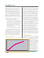
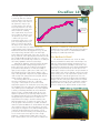
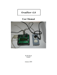
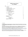
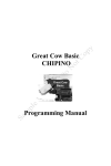
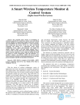
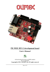
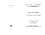
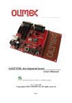
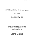
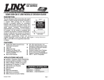
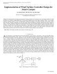
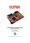
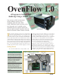
OvenFlow 1.0
A Program to Control SMD
Soldering Using a Toaster Oven
Ever want to try SMD (surface-mount
device) soldering without using a
magnifying glass and super steady
hands? Production houses use ovens which
cost thousands, but it’s possible to do a
reasonable job with a regular toaster oven.
You just need to control it correctly. Enter the
SparkFun Electronics Reflow Toaster Controller.
T
his controller looked like a great project for experimenting
with reflow soldering SMD devices at home, but it came
with only rudimentary software. As a learning project,
it had many features to explore, including a PIC16F88 MPU,
thermocouple temperature sensor using the A/D converter,
control buttons for inputs, an LCD readout, and a serial port
with boot loader for quick program changes. A personal goal
was to get back to low level (near assembly code) programming
after decades of being out of touch. Many months and 1,500
lines of C code later, this little controller can really do a lot,
including programmed modes and data logging to your PC.
Getting Started
The controller hardware kit is a snap to build — well
SAFETY NOTICES
by Kit Ryan
packaged components and no SMDs (!). It even includes a
power supply. All you need is a serial cable to hook it up to
your PC for programming as shown in Figure 1. A feature
of this kit is that the PIC16F88 already comes loaded with
a boot loader so a real programmer isn’t immediately
needed — but more on that later. The kit powers up with
the LED flashing and the LCD readout showing “Spark
Fun.” Very reassuring that everything works.
The circuit, shown in the schematic in Figure 2, is
designed to control a relay that can switch 120 VAC for
regulating the temperature of an ordinary toaster oven.
How it works is that the thermocouple output is amplified
and linearized by the Analog Devices AD849 IC to within
±2 degrees F. No adjustment is needed and I found it to
be within one degree of the reading compared to room
FIGURE 1. Completed controller project.
1) This project involves line voltage
connections which are potentially
fatal if mishandled. Double-check all
wires before applying line voltages.
2) Using the Controller for reflow
soldering can result in operating a
toaster oven at extremely high
temperatures, which can burn
fingers or cause fires.
3) Solder materials, whether leadbased or lead-free, can be toxic if
ingested. The toaster oven you
use for this project should be
permanently dedicated to electronics
and no longer used for heating food
products.
PLEASE USE CAUTION WHEN
OPERATING THIS CONTROLLER.
June 2008
67
OvenFlow 1.0
thermometers. The analog signal is between the range
of 0 to +5 volts and fed to one of the PIC port pins to
be sampled and converted to a 10-bit digital value. The
result is converted into a three-digit display and sent to the
LCD readout.
Board buttons labelled “Up,” “Down,” and “Select”
are sensed by other PIC port pins and are used by the
software to control the relay, temperature, and timer
functions. One helpful feature of the 16F88 is that you
can turn on “weak pull-ups” on its ports. This means the
button inputs will read five volts when not pushed and
zero volts when pushed without having to put extra
“pull-up” resistors to the five volt supply. It’s no wonder
the board looks so simple! The power supply regulates the
five volts for all the ICs. A MAX232 IC converts the 0 to
+5 volt digital signals to and from the PIC to the standard
±12 volt RS-232 levels for interfacing to the PC.
Something not supplied with the kit is the AC outlet
box seen in the picture. The relay wires are run to this box
to switch the hot side of the outlets. An alternative that
you may consider safer is to not mount the relay on the
Simple is Okay; Complicated is More Fun
Toaster ovens can get up to over 500 degrees F — hot
enough for SMD soldering. But heat alone is not enough.
It takes the right time/temperature profile to melt the
solder without destroying the parts or getting solder
bridges in the process. A typical SMD heating profile is
shown in Figure 3 (courtesy of Kester solder systems).
Having a required profile was what drove the need for a
“programmed mode.” Since the PIC16F88 can write its
own internal EEPROM memory to store a program, all
the pieces were there for a really capable circuit!
The schematic is reproduced with permission from
SparkFun Electronics. The BoostC header file is provided
with permission from BoostSource Technologies. (The
LG1
Logo
U1
Power
-IN
+IN
1
2
J1
R1
330
LOGO
D1
R2
S1
VCC
Vin
3
Vout
C1
100uF
1N4004
C2
100uF
7805
DC Power
D2
Temp
R1
1
2
JP1
RAW
GND
Status_LED
circuit board but put it inside the outlet box itself and just
run the low voltage control signal back to the controller
board. A significant amount of additional information on
the hardware, the build kit, and boot loader software is
available from the SparkFun website [1].
Status
VCC
U2
R6
10K
VCC
U3
+IN
1
2
3
4
5
6
7
IN+
+C
+T
COM
-T
-C
V-
-IN
-ALM
+ALM
V+
COMP
VO
FB
14
13
12
11
10
9
8
-IN
S2
Reset
D6
1
D7
2
3
Temp
4
VPP
GND
5
6
CS1
7
CS2
RX
8
Status_LED9
RA1/AN1
RA2/AN2/VREFRA3/AN3/VREF+ RA0/AN0
RA4/AN4
RA7/OSC1
RA5/VPP/MCLR RA6/OSC2
VSS
VDD
RB7/AN6/PGD
RB0/INT
RB6/AN5/PGC
RB1
RB5/TX
RB2/RX
RB4
RB3
18
17
16
15
14
13
12
11
10
D5
D4
E
R/W
VCC
CS3
RS
TX
Relay_Control
CS1
S3
Up
CS2
S4
Down
CS3
S5
Select
PIC16F88
Temp
C9
AD595
VCC
0.1uF
C8
VCC
RAW
LCD1
2x Quick-Connect Solder Lug Connection to Toaster
0.1uF
D3
1N4148
Relay_Control
R7
10K
GND
VCC
Contrast
RS
R/W
E
REL1
SPST-NO
Q1
NPN
C10
VCC
0.1uF
VCC
1N4148
VCC
VCC
10uF
GND
2
6
C5
Vs+
Vs-
RX1IN
TX1OUT
T1Out
T2Out
R1In
R2In
C1+
C1C2+
C2T1In
T2In
R1Out
R2Out
1
3
4
5
C6
10uF
R2
10K
Contrast
C7
10uF
11 TX
10
12 RX
9
15
RS232
10uF
TX1OUT 14
7
RX1IN 13
8
VCC
MAX232
GND
5
9
4
8
3
7
2
6
1
U4
VCC
JC1
GND
VCC
VEE
RS
R/W
E
D0
D1
D2
D3
D4
D5
D6
D7
BL+
BLLCD 16x2
16
C4
D4
1
2
3
4
5
6
7
8
9
10
D4
11
D5
12
D6
13
D7
14
15
GND 16
FIGURE 2. Controller schematic.
68
June 2008
OvenFlow 1.0
author is not affiliated in any way
with either company.)
FIGURE 3. Standard
reflow solder profile.
Controller Software
The software was developed
to be more flexible than just
controlling a toaster oven, should
you want to apply it to other
things. The original SparkFun
software — which does have many
useful basic code examples in it —
has been heavily modified and
expanded to get the resulting code
described here.
The 4K memory limit of the
PIC makes life really tough for
getting sophisticated with the
program. Every “extra” feature or
line of code was scrutinized. Heavy
use of functions (subroutines) was
required to eliminate redundant
code. The fact that only 200
useful for calibrating the oven (or making toast).
memory locations are left out of 4096 is an indication
of how tight it is. The user interface is further hindered
3) Semi-Automatic: The user can set a temperature and
having only 2x16 characters on the display and just three
the oven will track this temperature and turn the relay
control buttons (there is a fourth button for reset only),
on and off automatically. This can be used for very long
however, a lot can still be done as seen in Figures 4 and 5.
operations, such as chemical bath (e.g., etchant)
The top line contains the settings for the current
temperature control for several hours.
mode of operation and the second line shows the
functions for the three buttons, marked “up,” “down,” and
FIGURE 4. Main Menu LCD screen.
“select” on the PC board. Each button can
have two functions, depending on
Top line – Mode Select:
whether a short push or long push
“Main Menu” Screen:
Manual
(greater than two seconds) has been
Semi-Auto
Program 1
made. The slash mark “/” separates
Program 2
short/long functions.
Mode:
Manual
Setup
MM
x
x
Nx/Sel
A User Manual has been prepared
Current mode:
which details all the capabilities and
MM = Main Menu
operating procedures. The modes are
described briefly as follows:
“up” button function: “down” button function: “select” button function:
x = none
1) Main Menu: This comes up first after
the splash screen and allows the user to
select one of the five operating modes.
This is the basic “home” screen and
always available when exiting one of the
other modes. The only way to exit the
Main Menu is to turn off the unit!
2) Manual: Has a stop watch and
relay control plus displays the current
temperature. The user can manually
start/stop/reset the stop watch and turn
the relay on or off directly. This mode is
“Program” Screen:
Nx = next mode (short push)
/Sel = select this mode
(long push)
x = none
Timer
Program temperature (C or F)
Step Number
P1 = Program1
P2 = Program2
0 000s 000C 000C
P1 R/R Jmp Ed/Ex
Actual temperature
(C or F)
“up” button function:
“down” button function:
“select” button function:
R = run (short)
S = stop (short)
/R = reset timer (long)
Jmp = jump to next step
(short or long)
Ed = Go to edit mode (short)
/Ex = exit back to Main
Menu (long)
FIGURE 5. Program Mode LCD screen.
June 2008
69
OvenFlow 1.0
4) Program 1 and 2: This is the most capable mode of the
software, permitting the controller to follow a time/
temperature profile with up to 10 steps. Each step is
programmable by the user and both the setting and the
actual temperatures are displayed in real time. The
software comes with a built-in profile similar to the Kester
solder curve to make getting started easier. It can, of
course, be modified. A nice feature of the programmer is
that the steps for up to two programs are retained in the
EEPROM on the onboard PIC16F88 after the unit is
turned off. The LCD display for this mode shows how
much information can be crammed into just 32 characters.
5) Setup: Five variables can be modified to tailor the
controller to user preferences, including:
• Temperature units (Celsius or Fahrenheit).
• Time/temperature increment (during programming,
the amount of change for each button push can be
varied between one and 10 seconds or degrees).
• LED on with relay (gives a visual indication that the
relay has been switched on; kind-of a safety feature).
• Clock calibration (allows a ± 2% change to the
built-in system clock to get the one second timer
as accurate as desired).
• Time constant (helps the control system compensate
for the lag time in heating up the oven elements).
In addition, the controller program has a data logger
function which will output the time, set temperature,
actual temperature, and relay on/off conditions to your PC.
Data points are sent once per second. It uses the built-in
serial port on the board (a nice to have feature!) and is
directly readable by HyperTerminal or similar programs.
The data can be easily copied into Excel and analyzed or
plotted, as seen in some of the plots in this article.
Software Tools Selection
Every programmer has to select tools and it’s never an
300
250
200
150
100
50
easy choice. Cost, complexity (including the learning
curve), and capability are all factors. In selecting BoostC
over CC5X — which seems to be the standard compiler in
most articles — the cost differential of many $100s was
important. As this was my first PIC programming effort,
and not knowing whether I would like it or be successful
or ever want to do it again, I opted for a very low cost
entry into the process. It turns out that this compiler
behaves very well, the cost is incredibly low, and there is
excellent user support through the forums. I could often
get a response to a question back in 24 hours from the
creator of the compiler. I didn’t come across a single
bug either, although a few features could be improved,
such as error messages. It also integrates right into the
Microchip MPLAB IDE, too, for a consistent programming
environment. For those of you who want to tweak the
code with another compiler, there are several things which
must be changed globally, including: using small letters for
all the register names; changing the way binary numbers
are entered; and, of course, pragma usage.
The boot loader from SparkFun proved to be more
problematic. It worked perfectly over the serial port during
the early days of program development, when I was
making tons of stupid mistakes during the learning
process. However, when the program size became larger
than 2K (which is half of what the PIC16F88 can
accommodate), the process went “tilt.” There are some
peculiarities in the way the PIC programs jump to addresses
above 2K that are incompatible with the SparkFun boot
loading scheme. Luckily, by that point, my programming
skills had improved and I could use my ICD2 clone to
directly burn-in the program changes to the PIC. It was not
as onerous as I had originally thought, taking only about
30 seconds for a complete remove/burn/re-install cycle.
Cooking Right Along
To start, I suggest trying out the oven in Manual Mode;
just switching the relay on and leaving it there for perhaps
four minutes. Use HyperTerminal to collect the serial data
output and plot the heating
characteristic. First try, I ran into a
problem before the temperature
had peaked — the oven’s thermal
cutout safety switch clicked out
at 220°C, just enough for regular
solder to melt but not for lead-free
RoHS work. I found that by
adjusting the little metal tab on
the temperature dial inside the
oven cabinet, I could raise the
limit to 250°C, which is enough.
Of course, unplug the oven
before taking screwdriver in hand!
The second attempt then
0
0
70
50
June 2008
100
150
200
250
FIGURE 6. Toaster oven heating
curve — Manual Mode.
OvenFlow 1.0
looked like Figure 6. Notice there
250
is a time lag while the elements
heat up, then the slope increases
nicely. The slope of the curve at
200
any point is the “degrees per
second” that the oven can heat.
150
This is important since the slope
of the desired curve needs to be
able to match the soldering
100
curve requirements. If you need
more heating rate than the oven
can produce, you’re out of luck
50
— and need to get a more
powerful oven. My oven is a few
0
years old, luckily, and has 1,550
0
50
watts, so it can get up to about
two degrees C/sec. Many newer
ovens come with only 1,200 watts and may have
commensurately lower heating rates, although their
insulation may be better. My suggestion is to go to yard
sales and/or Craig’s list and look for one with a high
power rating. The toughest part of the curve to meet is at
the top, when the oven is already quite hot but where it still
has to climb quickly from about 180 degrees to 215 (leadbased solder) or 235 (RoHS) degrees in just 30 seconds, but
the heating capability is at its lowest (least slope).
Following the initial test, I then tried out the Program
Mode using the built-in settings that approximate the
Kester curve in five steps. If you allow for the warm-up
period, which takes about 20 seconds, the tracking is
quite good (see Figure 7; pink curve vs. blue curve). The
plot actually shows the result of much “tuning” of the
relay control algorithm compared to my original simplistic
“turn on relay if the temp is below the program; turn off
relay if it’s above” approach.
The final algorithm looks ahead about six seconds to
where the temperature needs to be — called the
“set_temp” — and compares it to where the actual
temperature appears to be headed: the “projected_temp.”
The weighting of the two values, the current temperature
error, and the projected temperature error, can be adjusted
to allow good tracking with different ovens. OvenFlow
allows for a time constant variable which the user can
adjust to help with the projected temperature function.
The initial warm-up time lag is best adjusted by inserting a
first program step of around 15-25 seconds at room
temperature before trying to track the soldering curve.
One interesting aspect of control loops (such as the one
in the program) is their tendency to oscillate around the
desired set point. Oscillations are clearly visible in the pink
curve. However, since it’s only a few degrees off at any
point, it appears adequate for the SMD soldering function
of interest. Another thing to be noted is the cool-off
period at the end of the heating cycle, starting at about
230 seconds. Toaster ovens appear to have enough
insulation — usually through a double skin of the oven
itself — that they don’t cool off very fast. According to the
FIGURE 7.
Program Mode
temperature
tracking.
Program Temp
Actual Temp
100
150
200
250
300
experts, the cool-down rate is important to get solder
joints that are not too brittle. One way that can work here
is to open the oven door in a controlled manner while
watching the actual temperature fall.
Yes, But Does It Work?
The moment of truth had come. I took an old PC
memory stick which has many surface-mount chips on it
with close leads (0.68 mm spacing), and removed one of
them using a heated air de-soldering tool. The back of the
board had new, unused pads on it to which I applied liquid
flux from a pen. Then I smeared on a thin layer of real
solder paste evenly across the pads to be representative of
what could be done at home without a custom cut solder
paste stencil, put one of the chips back in position on the
pads, and ran the controller program in the oven. The
photo in Figure 8 shows an excellent solder joint with no
bridges at all. The solder paste didn’t stick to the masked
and fluxed areas between the pins. I probably could have
applied a little more solder paste. This is not to say the
process is foolproof yet, but it looks like it can be made
FIGURE 8. Close-up of actual SMD soldering.
June 2008
71
OvenFlow 1.0
to work with a little effort.
Do It Yourself
The hardware is obtainable from
SparkFun Electronics and saves a lot
of time compared to assembling your
own circuit from scratch. If you do go
it alone, just be sure to follow the
schematic exactly and absolutely use
a PIC16F88 MPU because every PIC
is slightly different and the software
will likely not work with another
MPU. Add the outlet box and then
download the software from the Spark
Fun site. I’ve included two versions of
the program there for your enjoyment:
a .hex file that can be burned directly
into the MPU using a programmer,
and a C file and associated header
files in case you want to play around
with the program yourself. Do a
search for “reflow” to find the
controller info and files. Sorry, but
there’s no easy way around using a
programmer unless someone comes
up with a tiny bootloader that’s
compatible with the large program
size. This particular MPU is actually
designed for in-circuit programming
but that feature is not built into the
SparkFun kit and will probably
require some circuit modifications to
make it work. Even so, a programmer
would still be required.
Also posted on the SparkFun
website is a complete User Manual
for the program that explains all the
screens and control functions. That
manual includes a more in-depth
discussion of the software, too. Be
aware that the PIC16F88 has only
4K of program memory and the
program described in this article uses
95% of it! If you want to add more
features, you’ll likely have to cut
something out. NV
REFERENCES
[1] SparkFun Electronics controller
& software (ssparkfun.com)
[2] Kester SMD soldering
time/temp profile (kkester.com)
[3] BoostC C compiler (ssource
boost.com)
72
June 2008