1
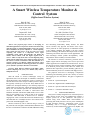
UACEE International Journal of Computer Science and its Applications - Volume 2: Issue 3 [ISSN 2250 - 3765] A Smart Wireless Temperature Monitor & Control System (ZigBee based Wireless System) Rohit B. Patil Rahul S. More Instrumentation & Comm. Group. CSIR-National Chemical Laboratory, Pune-411008, India. [email protected] Instrumentation & Comm. Group. CSIR-National Chemical Laboratory, Pune-411008, India. [email protected] Dnyanesh P. Joshi Dr. (Mrs.) Neelima S. Iyer Instrumentation & Comm. Group. CSIR-National Chemical Laboratory, Pune-411008, India. [email protected] Senior Principal Scientist & Head Instrumentation & Comm. Group. CSIR-National Chemical Laboratory, Pune-411008, India. [email protected] Abstract—The proposed paper focuses on developing an embedded application for temperature monitor and control along with data logging, by implementing ZigBee protocol for wireless data transmission. The system comprises of central computing unit at field side and receiver at the user side. The central computing unit consists of a temperature sensor, signal conditioning circuit, ARM7 microcontroller and ZigBee RF module, whereas ARM7, LCD and ZigBee together form a receiver. ARM’s on-chip 10-bit ADC is used for digitizing analog signals from the temperature sensor which are further processed for control & wireless transmission. With this utilization, it is possible to design a cost efficient, reliable and accurate system which is perfectly suitable for monitoring parameters in real time process dynamics especially in hazardous environments. and networking functionality mainly because, the IEEE 802.15.4 defines only physical and media access layers. Above protocols are either proprietary to individual vendors, or are industry standards, but ZigBee is the only wireless protocol technology that addresses the unique needs of remote monitoring and control and sensor network applications. The main advantages include product interoperability, vendor independence and accessibility to broader markets. The advances in wireless connectivity protocols such as ZigBee, augurs well for developing a low cost, low power and reliable application for industrial and commercial use. One of the major areas where wireless technology finds its application is in chemical process plants, where there are various vital parameters like temperature, pressure, humidity, pH levels etc. which continuously need to be monitored with high precision. Keywords—IEEE 802.15.4 standard, 4214A-XBEE, ARM7, Central Computing Unit (CCU), User Module (UM), Point to Multipoint Network. I. The proposed work aim’s at developing a temperature monitoring and controlling system with a facility of wireless data logging for user convenience. The paper is organized as follows: INTRODUCTION With the advent of wireless technologies variety of applications have been developed for industrial, commercial and medical fields. Such applications require a personal area network that focuses more on space around a person or object that typically extends up to few meters. Thus, IEEE 802.15.4 standard was developed adhering to the following important points namely lower data rate, simple connectivity and longer battery life. The standard specifies that communication can occur in the 868MHz, 915 MHz or 2.400-2.4835 GHz Industrial Scientific and Medical (ISM) bands. The 2.4 GHz band is more popular as it is open in most of the countries worldwide. This ISM band is divided into 16 channels, ranging from 2.405 to 2.480 GHz with each channel having a maximum data rate of 250kbps but due to the overhead of the protocol the actual throughput is less. Section II - System Description Section III - ZigBee Interface Methodologies Section IV - System Test Results and Analysis Section V - Conclusion and Future Scope. II. SYSTEM DESCRIPTION This system is mainly designed for use in chemical process plants wherein several users can simultaneously monitor a complex process for its vital parameters. The system is realized using 32-bit ARM7 RISC microcontroller as processing unit mainly because of its low power consumption & high operating frequency. Temperature sensor at the transmitting side is a K-type thermocouple. Wireless connectivity for data transmission is achieved by ZigBee. The Wireless connectivity can be achieved using a variety of RF protocols such as ZigBee, WirelessHART, MiWi that uses the 802.15.4 standard as a baseline and adds additional routing 56 UACEE International Journal of Computer Science and its Applications - Volume 2: Issue 3 [ISSN 2250 - 3765] system’s hardware and software development is explained with respect to CCU and UM as follows: 2) SOFTWARE The software application is developed in C using KEIL IDE and LPC2000 Flash Utility is used for ISP. This is a menu driven embedded application, which consists of 4*4 keypad for user interface and 20*4 LCD to display different parameters like set temperature, current temperature , set time period as well as system time (RTC). System first initializes all the peripherals like ADC, UART, LCD, RTC etc. One of the major part of initialization is to check, whether thermocouple is connected properly to system. If thermocouple is not connected or if it fails then a warning message will be displayed on LCD, and in this case no control action will be taken. Once the initialization phase is over, user has to enter the time period of the reaction and high limit set point for temperature. The time period entered by the user is used to configure the alarm registers of RTC. In normal conditions, system continuously monitors the current temperature and displays it on the LCD. The same values are simultaneously transmitted to the remote User Module via ZigBee. Data sent to User Module follows a certain protocol which includes start delimiter (0x7E) followed by actual temperature readings. A. Central Computing Unit (CCU) 1) HARDWARE The CCU hardware broadly comprises of following blocks (Refer Fig. 1): a) Temperature Sensor: K-type thermocouple is used as temperature sensor, having range of -270 to 1200 C. The weak signals coming from sensor are further amplified using signal conditioning circuit. b) Signal conditioning Circuit: In signal conditioning circuit AD595 is used, which is an instrumentation amplifier. It also provides thermocouple cold junction compensation; and combines an ice point reference with a pre calibrated amplifier to produce a high level (10 mV/C) output directly from a thermocouple signal. c) ARM7 Micro-controller: LPC 2148 microcontroller, with 32bit ARM7 TDMI core, which runs on 60MHz clock is the heart of this system. The on-chip 10 bit SAR-ADC, with 3.3V as Vref. and internal clock source of 1.5MHz is used to read sensor output. 16C550 industry standard UART simplifies the controller’s interface with the ZigBee module. Low power real-time clock with dedicated 32 kHz crystal, is used to keep track of user specified time limit along with alarm indications. d) Control Unit: Control unit consists of Solid Sate Relay (SSR) and Solenoid Valve which together controls the heating and cooling mechanisms. Cooling is achieved using a simple water cooled setup actuated by the solenoid valve. e) ZigBee Module: The ZigBee wireless module based on 4214A-XBEE from MaxStream has a 3.3V TTL compatible serial interface, which is interfaced with the ARM7’s UART. The RF module is configured to operate on standard baud rate of 9600 bps. In the initial stage, temperature is allowed to approach the set point value and then it is maintained by the control unit. Once the time period is expired, the system automatically shuts down and the alarm goes off. In an emergency case, when user wants to stop the reaction, a stop button is provided, which turns the heater off and starts the cooling action. The system can be brought back into the normal state by a reset switch. Fig. 2 explains the system flow. Fig. 1 CCU Block Diagram Fig. 2 System Flow Chart 57 UACEE International Journal of Computer Science and its Applications - Volume 2: Issue 3 [ISSN 2250 - 3765] Fig. 3 CCU Setup Fig. 5 User Module Setup B. User Module (UM) User module is an embedded device which facilitates user to observe the parameters of chemical process from a remote location (Refer Fig. 4). III. ZIGBEE TECHNOLOGY ZigBee devices are classified into two types based on their functionality viz. a) Full Function Device (FFD) and b) Reduced Function Device (RFD). Full Function Devices can perform all available operations within the standard. FFD decides the PANID and operating frequency of that PAN, and allows other end devices to associate with it. The RFDs are nothing but end devices, which do not perform any routing operations and are generally battery powered. In this system point to multipoint network is implemented, in which ZigBee module in CCU plays the role of FFD and other nodes (receivers) are configured as RFDs. The FFD broadcasts the temperature value to all of its nodes in the network. Due to this, all the RFDs having same PAN ID and channel frequency as that of CCU ZigBee module (FFD) can receive this data. Fig. 6 shows a typical star topology network. 1) Hardware: The main requirement while designing the User Module, was to make it portable and compact. It consists of ARM7 microcontroller, 20*4 LCD and a ZigBee module. The ZigBee modules used in User Module is configured to operate as RFD. Fig. 6 Star Network A. ZigBee configuration The ZigBee wireless module consists of different configurable registers which are used to set different network parameters. These parameters are stored in nonvolatile memory and can be modified by using ―AT Commands‖. ZigBee addressing along with some of the major registers like MY, DL, DH, PANID, CH are described below. Fig. 4 User Module Block Diagram 2) Software: There are two functions of ARM7, one is to display temperature value on LCD and the other is to send same data to PC via serial cable for data logging. The software running on PC receives this data and writes in to the Excel sheet. 58 UACEE International Journal of Computer Science and its Applications - Volume 2: Issue 3 [ISSN 2250 - 3765] signal, which allows the sharing of the same frequency band among multiple users. However the DSSS signal is further given to either BPSK (Binary phase shift keying) or O-QPSK (Offset - Quadrature phase shift keying) depending on whether the band is 868/915 MHZ or the 2.4 GHZ ISM band. For ZigBee based data transmission, DSSS is used followed by OQPSK for modulating radio-signals in physical layer. 1) ZigBee Addressing: The ZigBee module supports both short 16-bit addressing and long 64-bit addressing. A unique 64-bit IEEE source address (SL + SH) is assigned at the manufacturer’s side and 16bit address can be assigned by using AT commands. 2) Source Address: ―MY‖ or source address of RF module is a 16-bit address, which is unique for particular PAN. 3) Destination Address: In the same way DL and DH together form a destination address. In 16-bit addressing mode, DH must be zero and DL ranges from 0 - 0xFFFE, but if DL parameter of FFD is assigned 0xFFFF value, then it signifies that the message will be broadcasted to all nodes in network. Similarly, for 64-bit addressing, Destination Address (DL + DH) on the sender must match the Source Address (SL + SH) of the desired receiver. 4) PANID: An RF data network that consists of one Coordinator and one or more End Devices form a PAN (Personal Area Network). Each device in a PAN has a PAN Identifier [(PAN ID) parameter]. PAN IDs are unique to prevent miscommunication between different PANs. 5) CH (Channel No.): To improve security and reduce interference from other PANs, CH parameter is used. This parameter defines the actual frequency band from 2.40 2.4835 GHz to be used for a particular PAN, where adjacent channel rejection is 23 dB. The center frequency of operating band is calculated by using following formula. C. ZigBee’s performance compared to other wireless PAN standards The main parameters affecting the proper transmission and reception of wireless data are Bit Error Rate (BER) and Signal to Noise Ratio (SNR). BER: It is the average probability of symbol error also defined as the number of bit errors divided by the total number of transferred bits during a given period. SNR: It is defined as the ratio of signal power to the noise power. This ratio is usually measured in decibels (dB). Center Frequency = 2.405 + (CH - 11d) * 5 MHz Thus, in order to communicate properly, all the devices of the RF network should have the same PAN ID and CH number. In addition to all of these configuration settings there are two operating modes of ZigBee viz. a) transparent mode and b) API mode. a) Transparent Mode: The transparent mode is simplest and default mode of ZigBee which replaces the serial cable by RF link, due to this the data received on DI line of ZigBee is directly transmitted to the specified node. b) API Mode: The frame-based API (Application Programming Interface) mode extends the level to which a host application can interact with the networking capabilities of the RF module. Use of ZigBee in API mode enables the user application with some of the following features: -Transmitting data to multiple destinations without entering command mode. -Receive success/failure status of each transmitted RF packet. -Identify the source address of each received packet. Fig. 7 BER vs. SNR (dB) Generally to have a low BER, the SNR should be high or else the channel noise would severely affect the data transmission. Low SNR has the effect of introducing bit error in received signal. As can be seen from Fig.7, ZigBee has an acceptable level of BER for lowest SNR value, so that low strength signals can be transmitted without affecting the system fidelity, inferring longer battery life. IV. SYSTEM TEST RESULTS & ERROR ANALYSIS Here, some preliminary mathematical analysis of the system has been done, mainly to calculate some of the prime parameters viz. Mean error & Standard deviation. These parameters are calculated from the system test results. B. ZigBee modulation scheme Modulation technique for air interface varies according to frequency band in use. DSSS (Direct Sequence Spread Spectrum) modulation is common in all the bands, mainly because of the benefits that, the information signal is spread over a wide frequency band appearing like noise, which can be interpreted only by the intended receiver; offering resistance to unintended interference. Thus, DSSS modulation results in low probability of detection and interception of the transmitted A. Mean Error Mean error is calculated simply by taking the sum of all the error values (obtained from the difference between ideal temperature reading of the thermometer and the practical reading shown) and then dividing the same by the number of readings. In our case, the Mean Error was calculated to be 0.1723333. 59 UACEE International Journal of Computer Science and its Applications - Volume 2: Issue 3 [ISSN 2250 - 3765] B. Standard deviation It’s a mathematical tool to measure the dispersion of a set of data (in this case the set of data refers to the set of error values) from its mean. The more spread apart the error value, the higher the standard deviation, whereas a low standard deviation indicates that the error value tend to be very close to the mean error. Standard deviation is represented by symbol’σ’. V. CONCLUSION AND FUTURE SCOPE The designed system is tested in Chemical Engineering division, NCL and it is found that ZigBee operates properly within 60 meters line of sight and 25 meters indoors. Small size, low power consumption and open standard protocols makes ZigBee an indispensible option to develop a system, which is compact, reliable and flexible. Feature-rich ARM7 core processor integrated along with other on-chip peripherals makes LPC2148 microcontroller an all-in-one solution for designing such a real time system. The system described in this paper implements point to multipoint network, which can be transformed into an interconnected mesh of routers and end nodes, which pass information from node to node using the most efficient path. This can even facilitate the user module to take control of the system up to certain degree. Also the indoor range can be extended by using high-power ZigBee-pro module, incorporating 5dBi dipole antenna. As can be seen from the normalized graph in Fig. 8, usually one standard deviation about the central tendency covers approximately 68 % of the set of error values, two standard deviation covers 95 % and three standard deviation covers 99.7 %. ACKNOWLEDGMENT Our sincere thanks to Dr. Sourav Pal, Director, NCLIndia, for his constant support and encouragement, also to Dr. Vivek Ranade, Deputy Director and Chair, Chemical Engineering & Process Development Division, NCL, for believing in wireless instrumentation for chemical processes & allowing the implementation of this application for Chemical Engineering process. We are grateful to Dr. B.D. Kulkarni, Chairman, In house project committee, NCL, for granting the funds for this development at NCL. Thanks to our colleagues Deepak Kajale and Rohit Bhatkar, Research Interns, for their valuable help during development and testing phase. Fig. 8 Plot of a normal distribution (or bell curve) REFERENCES From the system test results and the mean error calculated above, the standard deviation for the above set of error values was calculated to be 1.123361, inferring that the error value’s are most likely to be between ± 1.123361 of the central tendency. Fig. 9 reflects the system characteristics. [1] LPC2141/42/44/46/48 – User Manual, Philips. [2] ―An Online Monitoring System of Contact Temperature inside HV Switchgear Cabinet Based on ZigBee Wireless Network‖. [3] XU Lei, ZHANG Hong-wei, LI Xiao-hui, WU Xian- liang ―A Design of Wireless Temperature and Humidity Monitoring System.‖ - IEEE 2010. [4] Analog Devices, Inc. (1999) AD595-Monolithic Thermocouple Amplifiers with Cold Junction Compensation. [5] Product Manual v1.xCx - 802.15.4 Protocol (XBee®/XBee-PRO® OEM RF Modules) [6] www.zigbee.org. Fig. 9 System Characteristics 60