1
LonWorks® to Modbus®
Module
VW3A58312PU
Instruction Bulletin
Retain for future use.
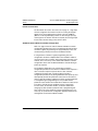
DANGER
HAZARDOUS VOLTAGE
•
Read and understand this bulletin in its entirety before installing
®
or operating Altivar 58 TRX drive controllers. Installation,
adjustment, repair, and maintenance of the drive controllers must
be performed by qualified personnel.
•
The user is responsible for conforming to all applicable code
requirements with respect to grounding all equipment.
•
Many parts in this drive controller, including printed wiring boards,
operate at line voltage. DO NOT TOUCH. Use only electrically
insulated tools.
•
DO NOT short across DC bus capacitors or touch unshielded
components or terminal strip screw connections with voltage
present.
Before servicing the drive controller:
•
Disconnect all power including external control power that may be
present before servicing the drive controller.
•
Place a “DO NOT TURN ON” label on the drive controller
disconnect.
•
Lock the disconnect in the open position.
•
WAIT TEN MINUTES for the DC bus capacitors to discharge.
Then follow the DC bus voltage measurement procedure on
page 13 to verify that the DC voltage is less than 45 V. The drive
controller LEDs are not accurate indicators of the absence of DC
bus voltage.
•
Install and close all covers before applying power or starting and
stopping the drive controller.
Failure to follow these instructions will result in death or serious
injury.
VVDED300055USR11/03
11/2003
LonWorks to Modbus Module
Contents
ENGLISH
SECTION 1: INTRODUCTION . . . . . . . . . . . . . . . . . . . . . . . . . . . . . . . . . . . . . . . . . . 7
PRODUCT OVERVIEW . . . . . . . . . . . . . . . . . . . . . . . . . . . . . . . . . . . . . . . . . . . . . . . 7
DRIVE FIRMWARE COMPATIBILITY. . . . . . . . . . . . . . . . . . . . . . . . . . . . . . . . . . . . . 9
REVISION LEVEL . . . . . . . . . . . . . . . . . . . . . . . . . . . . . . . . . . . . . . . . . . . . . . . . . 9
NEW FEATURES OF VERSION 1.1 LONWORKS TO MODBUS GATEWAY. . . . 9
RECEIVING, PRELIMINARY INSPECTION, AND STORAGE . . . . . . . . . . . . . . . . . 10
STATIC PRECAUTIONS . . . . . . . . . . . . . . . . . . . . . . . . . . . . . . . . . . . . . . . . . . . 10
ENVIRONMENTAL SPECIFICATIONS. . . . . . . . . . . . . . . . . . . . . . . . . . . . . . . . . . . 11
USING THIS MANUAL . . . . . . . . . . . . . . . . . . . . . . . . . . . . . . . . . . . . . . . . . . . . . . . 11
SECTION 2: HARDWARE SETUP AND WIRING . . . . . . . . . . . . . . . . . . . . . . . . . . 12
LONWORKS MODULE LAYOUT . . . . . . . . . . . . . . . . . . . . . . . . . . . . . . . . . . . . . . . 12
BUS VOLTAGE MEASUREMENT PROCEDURE . . . . . . . . . . . . . . . . . . . . . . . . . . 13
MECHANICAL INSTALLATION . . . . . . . . . . . . . . . . . . . . . . . . . . . . . . . . . . . . . . . . 15
LONWORKS MODULE . . . . . . . . . . . . . . . . . . . . . . . . . . . . . . . . . . . . . . . . . . . . 15
24 VDC POWER SUPPLY. . . . . . . . . . . . . . . . . . . . . . . . . . . . . . . . . . . . . . . . . . 16
MODBUS OPTION CARD (PART NUMBER VW3A58303U) . . . . . . . . . . . . . . . 16
ELECTRICAL WIRING . . . . . . . . . . . . . . . . . . . . . . . . . . . . . . . . . . . . . . . . . . . . . . . 16
CABLE ROUTING PRACTICES . . . . . . . . . . . . . . . . . . . . . . . . . . . . . . . . . . . . . 17
SECTION 3: CONTROL MODES . . . . . . . . . . . . . . . . . . . . . . . . . . . . . . . . . . . . . . 19
LOCAL AND REMOTE CONTROL MODES . . . . . . . . . . . . . . . . . . . . . . . . . . . . . . . 19
LOCAL (HAND) CONTROL. . . . . . . . . . . . . . . . . . . . . . . . . . . . . . . . . . . . . . . . . 20
REMOTE (AUTO) CONTROL . . . . . . . . . . . . . . . . . . . . . . . . . . . . . . . . . . . . . . . 21
FORCED LOCAL. . . . . . . . . . . . . . . . . . . . . . . . . . . . . . . . . . . . . . . . . . . . . . . . . . . . 21
© 2001–2003 Schneider Electric All Rights Reserved
5
LonWorks to Modbus Module
Contents
VVDED300055USR11/03
11/2003
SECTION 4: ATV58 TRX DRIVE CONTROLLER CONFIGURATION . . . . . . . . . . 22
ENGLISH
KEYPAD MODBUS PORT . . . . . . . . . . . . . . . . . . . . . . . . . . . . . . . . . . . . . . . . . . . . . 22
MODBUS OPTION CARD . . . . . . . . . . . . . . . . . . . . . . . . . . . . . . . . . . . . . . . . . . . . . 22
FORCED LOCAL FUNCTION . . . . . . . . . . . . . . . . . . . . . . . . . . . . . . . . . . . . . . . 23
ADDITIONAL ATV58 TRX DRIVE CONTROLLER CONFIGURATION . . . . . . . . 23
SECTION 5: LONWORKS CONFIGURATION . . . . . . . . . . . . . . . . . . . . . . . . . . . . 26
OPTIMIZING NETWORK PERFORMANCE . . . . . . . . . . . . . . . . . . . . . . . . . . . . . . . 26
INITIAL POWER-UP . . . . . . . . . . . . . . . . . . . . . . . . . . . . . . . . . . . . . . . . . . . . . . . . . 26
LONWORKS MODULE CONFIGURATION. . . . . . . . . . . . . . . . . . . . . . . . . . . . . . . . 27
NETWORK MASTER DEVICE. . . . . . . . . . . . . . . . . . . . . . . . . . . . . . . . . . . . . . . 28
SERVICE PIN . . . . . . . . . . . . . . . . . . . . . . . . . . . . . . . . . . . . . . . . . . . . . . . . . . . 28
WINK COMMAND . . . . . . . . . . . . . . . . . . . . . . . . . . . . . . . . . . . . . . . . . . . . . . . . 28
THE LONWORKS INTERFACE. . . . . . . . . . . . . . . . . . . . . . . . . . . . . . . . . . . . . . . . . 28
NETWORK VARIABLE TYPES . . . . . . . . . . . . . . . . . . . . . . . . . . . . . . . . . . . . . . 29
NODE OBJECT . . . . . . . . . . . . . . . . . . . . . . . . . . . . . . . . . . . . . . . . . . . . . . . . . . 30
DRIVE OBJECT . . . . . . . . . . . . . . . . . . . . . . . . . . . . . . . . . . . . . . . . . . . . . . . . . . 32
INPUT NETWORK VARIABLES FOR DRIVE CONTROL (NVI’S). . . . . . . . . . . . 34
INPUT NETWORK CONFIGURATION PROPERTIES FOR DRIVE
CONFIGURATION (NCI’S) . . . . . . . . . . . . . . . . . . . . . . . . . . . . . . . . . . . . . . . . . 35
OUTPUT NETWORK VARIABLES FOR DRIVE FEEDBACK (NVO’S) . . . . . . . . 40
SECTION 6: MINIMUM STARTUP PROCEDURE . . . . . . . . . . . . . . . . . . . . . . . . . . 44
MINIMUM STARTUP PROCEDURE . . . . . . . . . . . . . . . . . . . . . . . . . . . . . . . . . . . . . 44
SECTION 7: DIAGNOSTICS . . . . . . . . . . . . . . . . . . . . . . . . . . . . . . . . . . . . . . . . . . 46
LED STATES . . . . . . . . . . . . . . . . . . . . . . . . . . . . . . . . . . . . . . . . . . . . . . . . . . . . . . . 46
TROUBLESHOOTING . . . . . . . . . . . . . . . . . . . . . . . . . . . . . . . . . . . . . . . . . . . . . . . . 47
6
© 2001–2003 Schneider Electric All Rights Reserved
VVDED300055USR11/03
11/2003
Section 1: Introduction
Product Overview
SECTION 1: INTRODUCTION
PRODUCT OVERVIEW
The Altivar® 58 TRX (ATV58 TRX) family of adjustable frequency AC
drive controllers is used for controlling three-phase asynchronous
motors. They range from:
• 1 to 75 hp (0.75 to 55 kW) constant torque, 400/460 V,
three-phase input
• 1 to 500 hp (0.75 to 315 kW) variable torque, 400/460 V,
three-phase input
• 0.5 to 7.5 hp (0.37 to 5.5 kW) constant torque, 208/230 V,
single-phase input
• 0.5 to 30 hp (0.37 to 22 kW) variable torque, 208/230 V,
single-phase input
• 2 to 40 hp (1.5 to 30 kW) constant torque (50 hp variable torque),
208/230 V three-phase input
This bulletin explains how to integrate an ATV58 TRX drive controller
into a LonWorks® network with the LonWorks to Modbus® module.
Use this bulletin to install, wire, and configure the LonWorks module.
The VW3A58312PU LonWorks to Modbus module is a protocol
converter that allows the ATV58 TRX drive controller to be integrated
into a new or pre-existing LonWorks network with plug-and-play
simplicity. The LonWorks module can be incorporated into a new
drive installation or can be incorporated with an installed ATV58 TRX
drive controller.
The module uses the Echelon® free topology transceiver (FTT-10A).
The transceiver connects to the LonWorks network via a single
twisted pair cable with a data transmission rate of 78 kbps. The
compact module is connected point-to-point through the supplied
29.5 in. (750 mm) cable to either the ATV58 TRX integrated keypad
Modbus port or to the 9-pin connector on the Modbus option card
(part number VW3A58303U). The user must supply 24 Vdc power
separately. The module is DIN rail mounted. External Interface files
(XIF, versions 4.4, 4.1, 3.1, and 2.0) and Device Resource files are
supplied on diskette.
© 2001–2003 Schneider Electric All Rights Reserved
7
Section 1: Introduction
Product Overview
VVDED300055USR11/03
11/2003
When connected to the LonWorks module, the ATV58 TRX drive
controller joins other HVAC devices in a low-cost building control
network. As a node on the network, the ATV58 TRX drive controller
provides the following functions:
•
•
•
•
•
Command and setpoint control
PI process control
Adjustment and configuration
Monitoring values such as motor speed, current, and drive status
Display of kilowatt hours and total run time on drive controllers with
ATV58 TRX drive controller firmware version 4.0 or later
• Remote fault reset
• Module and drive controller diagnostics
The LonWorks module for the ATV58 TRX drive controller complies
with LonMark® Interoperability Guidelines Version 3.3 and with the
LonMark Functional Profile for Variable Speed Motor Drives 6010
Version 1.1. Information on the LonWorks network is available from
www.lonmark.org and www.echelon.com. Information on the ATV58
TRX drive controller is available from www.SquareD.com.
WARNING
LOSS OF CONTROL
• The designer of any control scheme must consider the potential
failure modes of control paths and, for certain critical control
functions, provide a means to achieve a safe state during and after
a path failure. Examples of critical control functions are emergency
stop and overtravel stop. Separate or redundant control paths must
be provided for critical control functions.
• System control paths may include communication links.
Consideration must be given to the implications of unanticipated
transmission delays or failures of the link.
Failure to follow these instructions can result in death, serious
injury, or equipment damage.
NOTE: For additional information, refer to NEMA ICS 1.1 (latest
edition), Safety Guidelines for the Application, Installation, and
Maintenance of Solid State Control, and to NEMA ICS7.1 (latest
edition), Safety Standards for Construction and Guide for Selection,
Installation, and Operation of Adjustable-Speed Drive Systems.
8
© 2001–2003 Schneider Electric All Rights Reserved
VVDED300055USR11/03
11/2003
Section 1: Introduction
Drive Firmware Compatibility
To use the LonWorks module, the installer must supply separate
equipment:
• If the ATV58 TRX drive controller does not have a keypad display
installed, a programming option must be supplied (only one
programming option is necessary to configure one or multiple
drives):
— Keypad display (part number VW3A58101)
— PowerSuite Software on CD (part number VW3A8104) and
PC connection kit (part number VW3A8106)
• For each drive controller that has a keypad display permanently
installed, supply a Modbus option card (part number
VW3A58303U).
• A power supply (24 Vdc ± 20%) for the LonWorks module. Each
module requires a maximum of 140 mA.
• A 35-mm DIN rail for mounting the module.
• A Local/Off/Remote operator must be installed as shown on
page 20.
DRIVE FIRMWARE COMPATIBILITY
The LonWorks to Modbus module is compatible with ATV58 TRX
drive controllers loaded with firmware version V3.1 IE16 and later.
Kilowatt hours and total run time values are available with
ATV58 TRX drive controller firmware version 4.0 and later. The label
indicating the firmware version is located on the main control board
just above the keypad Modbus port (see Figure 2 on page 14).
Revision Level
This release is for version 1.1 of the VW3A58312PU LonWorks card.
New Features of Version 1.1 LonWorks to Modbus Gateway.
Version 1.1 features the following enhancements.
Network Variable Documentation Strings
Documentation strings for all network variables are stored directly in
the gateway, so you can install the gateway onto a LonWorks system
without using the XIF files. This feature provides function-related
name strings for all network variables.
© 2001–2003 Schneider Electric All Rights Reserved
9
Section 1: Introduction
Receiving, Preliminary Inspection, and Storage
VVDED300055USR11/03
11/2003
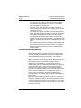
Network Variable Aliases
Version 1.1 supports up to 46 network variable aliases, used to
circumvent the binding constraints in some installation scenarios.
Network variables are used when connecting an output variable on
one node to several input variables on another single node, to ensure
that each binding gets a unique selector value. Normally, the network
management tool (such as LonMaker™ for Windows) handles the use
of network variable aliases, making it transparent to the user.
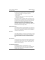
RECEIVING, PRELIMINARY INSPECTION, AND STORAGE
Before installing the LonWorks module, read this manual and follow
all precautions.
Before removing the module from its packing material, verify that
there is no shipping damage to the packing carton. Damage to the
packing carton usually indicates improper handling and the potential
for device damage. After removing the module from its packaging,
inspect its exterior for shipping damage. If any damage is found, notify
the carrier and your local Square D/Schneider Electric representative.
Do not install a damaged device.
Ensure that the part number printed on the box label is the same as
the number on the packing slip and corresponding purchase order.
Verify that the information on the module nameplate matches the box
label. Contact your local Square D/Schneider Electric representative
if there are any errors.
The package should contain the following four items:
1. LonWorks to Modbus module
2. Interconnecting cable from the module to the drive
3. Diskette with External Interface Files (XIF) and Device Resource
Files for the LonWorks installation tool
4. Instruction bulletin
Static Precautions
Observe the following precautions for handling static sensitive
components when removing the module from its packaging for
installation:
• Keep static producing material (plastic, upholstery, carpeting, etc.)
out of the immediate work area.
• Avoid touching conductors with skin or clothing.
10
© 2001–2003 Schneider Electric All Rights Reserved
VVDED300055USR11/03
11/2003
Section 1: Introduction
Environmental Specifications
To store the module, replace it in its original package (including the
antistatic bag) and store it in a clean, dry area where the ambient is
between -13 to 158 °F (-25 to 70 °C).
ENVIRONMENTAL SPECIFICATIONS
Enclosure type
IP20 (Standard EN50178)
Resistance to vibration
1.5 mm zero to peak from 3 to 13 Hz
1 g from 13 to 150 Hz
(IEC 60068-2-6)
Resistance to shock
15 g for 11 ms (IEC 60068-2-27)
Ambient pollution degree
Pollution degree 2 (IEC 664-1 and UL840)
Relative humidity
95% maximum at +50 °C, non-condensing and
without dripping (IEC 60068-2-3)
Ambient temperature
Storage: -13 to 158 °F (-25 to 70 °C)
Operation: 32 to 122 °F (0 to 50 °C)
Altitude
9900 ft (3000 m) maximum
EMC immunity and emissions
Complies with IEC 61000-6
Certifications
cULus, CE marked
USING THIS MANUAL
To prepare the ATV58 TRX drive controller for connection to a
LonWorks network, refer to the following sections:
•
•
•
•
“Section 2: Hardware Setup and Wiring” on page 12
“Section 3: Control Modes” on page 19
“Section 4: ATV58 TRX Drive Controller Configuration” on page 22
“Section 5: LonWorks Configuration” on page 26
For startup, refer to “Section 6: Minimum Startup Procedure” on
page 44. Refer to “Section 7: Diagnostics” on page 46 for
troubleshooting assistance. For information about specific drive
controller parameters, see Instruction Bulletin VVDED397047US
(latest revision), ATV58 TRX Keypad Display. For information on the
installation, start-up, wiring, and maintenance of the drive controller,
refer to the installation guide delivered with the drive controller.
© 2001–2003 Schneider Electric All Rights Reserved
11
Section 2: Hardware Setup and Wiring
LonWorks Module Layout
VVDED300055USR11/03
11/2003
SECTION 2: HARDWARE SETUP AND WIRING
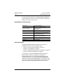
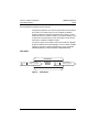
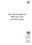
LONWORKS MODULE LAYOUT
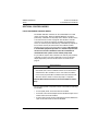
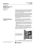
Figure 1 identifies the layout of the LonWorks module: the LonWorks
connector (1), the service pin (2), the diagnostic LEDs (3), the
Modbus RJ45 female port (4), the power supply connector (5), and
the 35-mm DIN-rail connector (6).
1.4 in
3 in
35 mm
77 mm
Shield
1
2.0 in
NET B
NET A
51 mm
3.7 in
C
L
of DIN-Rail
Mount
2
93 mm
3
6
LONWORKS Status
Module Status
Service
Wink
Front View
Right Side View
4
5
3.0 in
77 mm
Bottom View
Figure 1:
12
LonWorks Module Layout
© 2001–2003 Schneider Electric All Rights Reserved
VVDED300055USR11/03
11/2003
Section 2: Hardware Setup and Wiring
Bus Voltage Measurement Procedure
BUS VOLTAGE MEASUREMENT PROCEDURE
Verify that all power has been removed from the ATV58 TRX drive
controller as well as from any other connected equipment on the
panel or in the enclosure before installing the LonWorks to Modbus
module. Before connecting the module to the ATV58 TRX drive
controller, measure the bus voltage as described in this section.
DANGER
HAZARDOUS VOLTAGE
•
Read and understand the bus voltage measurement procedure
before performing the procedure. Measurement of bus capacitor
voltage must be performed by qualified personnel.
•
DO NOT short across DC bus capacitors or touch unshielded
components or terminal strip screw connections with voltage
present.
•
Many parts in this drive controller, including printed wiring boards,
operate at line voltage. DO NOT TOUCH. Use only electrically
insulated tools.
Electrical shock will result in death or serious injury.
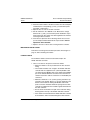
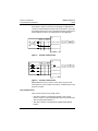
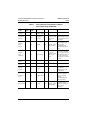
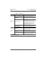
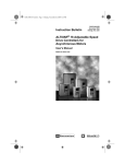
The DC bus voltage level is determined by monitoring the (+) and (–)
measurement points. Their location varies by drive controller model
number as listed in Table 1 and shown in Figure 2 on page 14. The
drive controller model number is listed on the nameplate.
Table 1:
(+) and (–) Measurement Points
Drive Controller
Catalog Number
ATV58••••••
(+) Measurement Point
Terminal
Block or
Connector
Terminal
Terminal
Block or
Designation
Connector
Terminal
Designation
(+)
J2
(–)
J2
PA
J18
7
J2
(+)
J2
(–)
U09M2• and U18M2• J2
U29M2• to D12M2•
U18N4• to D23N4•
D16M2• to D46M2•
D28N4• to D79N4•
C10N4X to C33N4X
© 2001–2003 Schneider Electric All Rights Reserved
(–) Measurement Point
PA (+)
PC (–)
13
Section 2: Hardware Setup and Wiring
Bus Voltage Measurement Procedure
VVDED300055USR11/03
11/2003
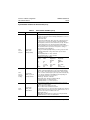
To measure the DC bus capacitor voltage:
1. Disconnect all power from the drive controller including external
control power that may be present on the control board and the
option board terminals.
2. Wait 10 minutes for the DC bus capacitors to discharge.
The J18 connector is in the upper left-hand corner of the main control
board behind the flexible shield. Use a thin probe to access the
connector pin.
J18-7
Flexible
Shield
–
+
J18
} ATV58•U29M2–D12M2
ATV58•U18N4–D23N4
L1 L2 L3 PA PB U
+
–
Keypad Modbus
Port Label
L1 L2 +
–
} ATV58•U09M2–U18M2
V W
U
+
–
Main Control
Board
L1 L2 L3 +
} ATV58•D16M2–D46M2
ATV58•D28N4–D79N4
– PA PB U
+
–
Power
Terminal
Block
V W
} ATV58HC10N4X
PA PA PC
L1 L2 L3 U
Do Not Use
V W
V
W
U
V
L1 L2 L3
PA
PC
–
+
}
W
ATV58HC13N4X–C19N4X
L1 L2 L3
PC
PA PA U
+
–
Figure 2:
14
}
V
W
ATV58HC23N4X–C33N4X
DC Bus Voltage Measurement Point Locations
(ATV58HU09M2 shown)
© 2001–2003 Schneider Electric All Rights Reserved
VVDED300055USR11/03
11/2003
Section 2: Hardware Setup and Wiring
Mechanical Installation
3. Read the model number of the drive controller from the nameplate
and identify the corresponding (+) and (–) measurement points
from Table 1 and Figure 2.
4. Open the door or cover of the drive controller.
5. Set the voltmeter to the 1000 Vdc scale. Measure the voltage
between the (+) and (–) measurement points identified in step 3.
Verify that the DC bus voltage has discharged below 45 V before
servicing the drive controller.
6. If the DC bus capacitors will not discharge below 45 V, contact
your local Square D/Schneider Electric representative. Do not
operate the drive controller.
7. Replace all covers or doors after servicing the drive controller.
MECHANICAL INSTALLATION
Perform the bus voltage measurement procedure, which begins on
page 13, before installing the module.
LonWorks Module
The LonWorks module cannot be mounted internally to the
ATV58 TRX drive controller.
1. Choose a location on the panel to mount the module.
— Mount the module as far as possible from the line and load
wiring.
— The module should be near enough to the ATV58 TRX drive
controller that the supplied 29.5 in. (750 mm) Modbus cable
can extend from the Modbus port on the module to the Modbus
port on the ATV58 TRX drive controller. Ensure that there is
sufficient slack in the cable to avoid stress on the Modbus port
connectors.
— Maintain a minimum of 1 in. (25 mm) spacing around the top
and sides of the module. Allow 3 in. (75 mm) minimum on the
bottom of the module for making the Modbus and 24 Vdc
power connection. Maintain minimum spacing from the drive
controller as published in the installation guide delivered with
the drive controller.
— Do not mount the module in the path of the heated air being
discharged from the top of the ATV58 TRX drive controller.
— If the module is mounted below the ATV58 TRX drive controller,
do not block the airflow circulated through the drive heatsink.
© 2001–2003 Schneider Electric All Rights Reserved
15
Section 2: Hardware Setup and Wiring
Electrical Wiring
VVDED300055USR11/03
11/2003
2. Securely fasten to the panel DIN rail of sufficient length to allow the
module and any necessary end stops to be attached. The distance
from the top of the module to the center of the DIN rail is
2 in. (50 mm).
3. Ensure that the DIN rail is properly grounded.
4. Attach the module to the DIN rail. The metal plate on the module
should contact the DIN rail to provide a ground path.
24 Vdc Power Supply
1. The LonWorks module must be supplied with 24 Vdc (± 20%). It
draws a maximum current of 140 mA.
2. Follow the manufacturer’s instructions when mounting the power
supply to the panel.
Modbus Option Card (Part Number VW3A58303U)
1. If a keypad display is regularly installed on the ATV58 TRX drive
controller, a Modbus option card must be installed into the drive
controller to supply a Modbus port connection for the LonWorks
module.
2. Follow the instructions in user’s manual VVDED397054US,
delivered with the Modbus option card, to install the card into the
ATV58 TRX drive controller.
ELECTRICAL WIRING
1. Route all wiring to the LonWorks module as far as possible from
the drive controller line and load power wiring. Avoid parallel cable
runs. Follow the recommendations in the section “Cable Routing
Practices” on page 17.
2. Modbus connection:
— Attach the supplied Modbus cable’s RJ-45 connector to the
Modbus port on the module (see Figure 1 on page 12).
— If the ATV58 TRX drive controller is not supplied with a Modbus
option card, connect the 9-pin Sub-D connector on the Modbus
cable to the keypad Modbus port on the drive controller. Refer
to Figure 2 on page 14 for the location of the keypad Modbus
port. Make make this connection after the drive controller
configuration has been completed. See “Section 4: ATV58 TRX
Drive Controller Configuration” on page 22.
16
© 2001–2003 Schneider Electric All Rights Reserved
VVDED300055USR11/03
11/2003
Section 2: Hardware Setup and Wiring
Electrical Wiring
— If the ATV58 TRX drive controller is supplied with a Modbus
option card, connect the 9-pin Sub-D connector on the Modbus
cable to the option card Modbus port. Refer to the user’s
manual supplied with the Modbus option card for the location
of the port.
3. LonWorks connection:
— The LonWorks module accepts a two-conductor shielded
cable as recommended for LonWorks networks. The
connector accepts wire sizes from 16 AWG (1.3 mm) to
24 AWG (0.5 mm).
— Secure the two conductors of the LonWorks network cable to
terminals “NET A” and “NET B” of the LonWorks pull-apart
connector on the front of the module (see Figure 1 on page 12).
The connections are polarity insensitive.
— Secure the cable shield to the “SHIELD” terminal.
— Torque these connections to 2 lb-in (0.22–0.25 N•m).
4. Power supply connection:
— Connect the two wires from the 24 Vdc power supply to the
pull-apart terminal block on the bottom side of the LonWorks
module. Be sure to observe connection polarity.
— Use wire size between 12 AWG (2.5 mm) to 24 AWG
(0.5 mm).
— Torque these connections to 4–5 lb-in (0.5–0.6 N•m).
Cable Routing Practices
When wiring the ATV58 TRX drive controllers to a LonWorks network,
follow all wiring practices required by national and local electrical
codes.
Avoid areas of high temperature, moisture, vibration, or other
mechanical stress. Secure the cable where necessary to prevent its
weight and the weight of other cables from pulling or twisting the
cable. Use cable ducts, raceways, or other structures for protecting
the cable. These structures should be used for signal wiring paths and
should not contain power wiring.
Avoid sources of electrical interference that can induce noise into the
cable. Use the maximum practical separation from such sources.
© 2001–2003 Schneider Electric All Rights Reserved
17
Section 2: Hardware Setup and Wiring
Electrical Wiring
VVDED300055USR11/03
11/2003
When planning cable routing within a building, follow these
guidelines:
• Maintain a minimum separation of 3.3 ft (1 m) from the following
equipment: air conditioners, elevators, escalators, large blowers,
radios, and televisions; intercom and security systems; and
fluorescent, incandescent, and neon lighting fixtures.
• Maintain a minimum separation of 10 ft (3 m) from the following
equipment: power wiring, transformers, generators, and
alternators.
When wiring in electrical equipment rooms or large electrical
equipment line-ups, observe the following guidelines for cable
segregation and separation of circuits:
• Use metallic conduit for drive controller wiring. Do not run control
network and power wiring in the same conduit.
• Separate non-metallic conduits or cable trays used to carry power
wiring from metallic conduit carrying low-level control network
wiring by at least 12 in (305 mm).
• Separate metallic conduits carrying power wiring or low-level
control network wiring by at least 3 in (76 mm).
• Cross the metallic conduits and non-metallic conduits at right
angles whenever power and control network wiring crosses.
• Attenuate conducted emissions from the drive controller to the line
in some installations to prevent interference with
telecommunication, radio, and sensitive electronic equipment.
Such instances may require RFI filters or line reactors. Consult the
Altivar 58 TRX AC Drive Catalog (8806CT9901) for selection and
application of these filters.
For additional information on wiring guidelines for LonWorks
networks and a list of cable vendors, refer to the LonWorks
Engineering Bulletin, Junction Box and Wiring Guidelines for Twisted
Pair LonWorks Networks, Part No. 005-0023-1. This bulletin is
available on the Echelon website at www.echelon.com.
18
© 2001–2003 Schneider Electric All Rights Reserved
VVDED300055USR11/03
11/2003
Section 3: Control Modes
Local and Remote Control Modes
SECTION 3: CONTROL MODES
LOCAL AND REMOTE CONTROL MODES
The ATV58 TRX drive controller can be commanded in local and
remote control modes. When the ATV58 TRX drive controller is
powered up, it defaults to local (hand) control. Refer to the discussion
of local and remote control on page 20. After the drive controller
recovers from a power-up sequence (including such unplanned
events as an AC line power disturbance), it immediately responds to
local controls that may be active before the LonWorks module
initializes and assumes control of the drive controller. This will result
in unintended equipment operation. It is therefore required that
all local run and start commands to the drive controller be
removed when the system is in the remote (auto) mode.
It is possible to stop the drive controller in the remote (auto) mode by
activating one of the local stop commands (such as the keypad
display stop button). Refer to the discussion of forced local on
page 21.
WARNING
UNINTENDED EQUIPMENT OPERATION
•
Commands sent over the LonWorks network can restart the drive
controller if the drive controller is not in a forced local condition.
•
It is necessary to put the drive controller into the forced local mode
when the selector switch is in the local (hand) or off position.
Failure to follow these instructions can result in death or serious
injury.
The user must provide a 3-position selector switch with the following
functionality:
• In local (hand) mode, forced local must be enabled.
• In off mode, all run terminal inputs must be disabled via open circuit
and forced local must be enabled.
• In remote (auto) mode, the run terminal inputs must be disabled via
open circuit and forced local must be disabled.
© 2001–2003 Schneider Electric All Rights Reserved
19
Section 3: Control Modes
Local and Remote Control Modes
VVDED300055USR11/03
11/2003
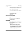
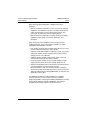
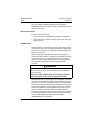
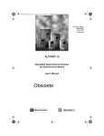
See Figures 3 and 4 for assistance in designing Local/Off/Remote
control. For the Run Reverse and Forced Local functions, select any
unused logic inputs on the main control board. Assign a logic input to
the Run Reverse function only if appropriate for the application.
Local
(Hand)
Off
Remote
(Auto)
User
Control
Scheme
+24
LI1 Run Forward
The cross hatch
under
the selector switch position
indicates a closed contact.
LIx Run Reverse
LIy Forced Local
Figure 3:
Example 2-Wire Control
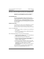
+24
Local
Remote
(Hand) Off (Auto)
Stop
LI1 Stop
Fwd
LI2 Run Forward
The cross hatch
under
the selector switch position
indicates a closed contact.
Rev
LIx Run Reverse
LIy Forced Local
Figure 4:
Example 3-Wire Control
NOTE: While the selector switch is in the remote (auto) position,
removing the local run forward or run reverse commands will not stop
the drive controller.
Local (Hand) Control
There are two modes of local (hand) control:
• The drive controller is managed by operators such as push
buttons, switches, and a speed potentiometer that are wired to the
drive controller terminal block, or
• The drive controller is managed by the digital keypad display
buttons.
20
© 2001–2003 Schneider Electric All Rights Reserved
VVDED300055USR11/03
11/2003
Section 3: Control Modes
Forced Local
Refer to the ATV58 TRX Keypad Display Instruction Bulletin,
VVDED397047US, for more details on how to select between the two
modes of local control.
Remote (Auto) Control
In remote (auto) control mode:
• The drive controller is managed by the LonWorks serial network.
• The speed reference and the start/stop control cannot come from
separate sources.
FORCED LOCAL
Switching between local and remote control is achieved by a switch
wired to a logic input on the controller terminal block as illustrated in
Figures 3 and 4 on page 20. The logic input must be assigned to the
function “Forced Local”.
When the logic input assigned to forced local is active (high), all
control of the drive controller is assigned to the selected local (hand)
control mode. In this case, command requests by the LonWorks
network are refused. Command parameters can be monitored. All
other adjustment and display parameters can be read/write
accessed.
WARNING
LOSS OF CONTROL
When in forced local mode, all commands from the communication
ports are ignored.
Failure to consider the implications of unanticipated operation
can result in death, serious injury, or equipment damage.
When the logic input is not active (low), all management of the drive
controller is transferred to the LonWorks network if wired as shown in
Figures 3 or 4. The only local (hand) controls that are still monitored
by the drive controller include the logic input assigned to Forced Local
and any input assigned to a drive controller stop function. Examples
include the stop button on the keypad display, logic input one (LI1)
which is assigned to the function STOP if the ATV58 TRX drive
controller is configured for 3-wire control, and any logic input assigned
to the functions freewheel stop, DC injection braking, and fast stop.
See the ATV58 TRX Keypad Display Instruction Bulletin,
VVDED397047US, for more details.
© 2001–2003 Schneider Electric All Rights Reserved
21
Section 4: ATV58 TRX Drive Controller Configuration
Keypad Modbus Port
VVDED300055USR11/03
11/2003
SECTION 4: ATV58 TRX DRIVE CONTROLLER CONFIGURATION
Configuration of the ATV58 TRX drive controller is dependant on
which port is used for the Modbus connection to the module.
KEYPAD MODBUS PORT
If the cable from the LonWorks module is attached to the drive
controller keypad Modbus port, the address of the ATV58 TRX drive
controller must be set to 1. Using the keypad display or test and
commissioning software, set the Add parameter (Menu 4) to a value
of 1. Do not change the baud rate of the keypad port; this renders the
keypad inoperable.
MODBUS OPTION CARD
If the Modbus option card (part number VW3A58303U) is installed in
the drive controller and the cable from the LonWorks module is
attached to the option card port, the following settings must be made.
Switches on the Modbus Card
1. Set the card to an address of 1. Only DIP switch 7 should be up in
the “1” position.
2. Set both of the configuration switches to Modbus/JBUS position.
This is the rightmost position.
Menu 8 through Keypad Display or Test and Commissioning Software
1. Verify that the address (AdrC) is set to 1. This is determined by the
address switches on the Modbus card.
2. Verify that the protocol (Pro) is set to Modbus/RTU.
3. Set the transmission speed (bdr) to a baud rate of 9,600 bps. (It is
possible to configure bdr to 19,200 bps. The module will
autodetect to 9600 or 19,200 bps.)
4. Set format (For) to 8N1 for 8 data bits, no parity, and 1 stop bit.
5. After changing the baud rate setting of the optional Modbus card,
cycle power to the LonWorks gateway to re-establish
communications between the gateway and the drive controller at
the new baud rate.
For more information, see Instruction Bulletin VVDED397054US,
supplied with the VW3A58303U Modbus option card.
22
© 2001–2003 Schneider Electric All Rights Reserved
VVDED300055USR11/03
11/2003
Section 4: ATV58 TRX Drive Controller Configuration
Modbus Option Card
Forced Local Function
As described in the section “Forced Local” on page 21, a logic input
must be assigned to the function Forced Local. Using the keypad
display or test and commissioning software, enter the I/O Menu
(Menu 5 on the keypad display). Select an unused Logic Input (LI)
and assign it to the function Forced Local (FLO). Use this logic input
for Forced Local when wiring in the selector switch.
Additional ATV58 TRX Drive Controller Configuration
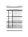
Table 2 on page 24 lists the subset of ATV58 TRX drive controller
configuration parameters that are accessible both through the drive
controller's regular programming tools (keypad display or test and
commissioning software) and over the LonWorks network.
If using the drive controller’s regular programming tools, this
configuration should be completed before the LonWorks module is
connected to the drive controller and configured for operation on the
network. This is necessary as the module will read drive controller
configuration values from the ATV58 TRX drive controller during its
power-up sequence.
The LonWorks module does not read the drive controller's
configuration parameters each time the LonWorks master requests a
value. Instead, to improve response time for drive controller
commands and status data, it reads the drive controller's
configuration parameters only during initialization after power-up, and
subsequently provides the parameter values from its own internal
memory. After the module is initialized, if a drive controller parameter
is changed through a programming tool, it is possible that the
parameter value stored in the module will not match the value stored
in the drive controller and the LonWorks master could read an
incorrect value. To avoid this situation, restart the module after
changing any drive controller parameter with a programming tool.
Also note that for some LonWorks network management tools, it is
necessary to synchronize the configuration properties between the
management tool and the LonWorks module.
© 2001–2003 Schneider Electric All Rights Reserved
23
Section 4: ATV58 TRX Drive Controller Configuration
Modbus Option Card
Table 2:
VVDED300055USR11/03
11/2003
Drive Controller Configuration Parameters
Accessible through the Network
Parameter Keypad Keypad
Name
Menu
Code
Range
Low Speed
Setpoint
2
LSP
0 to HSP setting Hz
0
High Speed
Setpoint
2
HSP
LSP setting to
tFr setting
50 or 60 Hz
(depends on main
control board
switch)
tFr is the drive controller's
maximum frequency limit
which cannot be set over
the network
Depends on drive
controller rating
Rated RPM as listed on
motor nameplate. This
value is used in
calculating the drive
controller output speed
value.
Nominal
Motor
Speed
3
nSP
0 to 9999
Units
Hz
RPM
Factory Setting Comments
Rated frequency as listed
on the motor nameplate.
50 or 60 Hz
This is set by the position
(depends on main
of the 50/60 Hz switch on
control board
the main control board.
switch)
The network can overwrite
this value.
Nominal
Motor
Frequency
3
FrS
40 to tFr setting Hz
Acceleration
Time 1
2
ACC
0.05 to 999.9
second 3
Deceleration
2
Time 1
dEC
0.05 to 999.9
second 3
Energy
Saving
nLd
No - yes
Controlled
Stop
3
6
Current Limit 3
24
StP
CLI
Yes
Choice valid only if drive
controller macro
configuration is set for
variable torque
No - NMS - FRP
No
Drive controller action
upon loss of an input
phase. See keypad
manual,
VVDED397047US for
further description.
0 to 136%
Depends on drive
controller rating
Percent of drive
controller's constant
torque current rating. See
drive controller
nameplate.
0.1 A
© 2001–2003 Schneider Electric All Rights Reserved
VVDED300055USR11/03
11/2003
Section 4: ATV58 TRX Drive Controller Configuration
Modbus Option Card
Table 3 is a partial list of other drive controller configuration changes
that may also need to be changed before operating the system. These
parameters are not accessible over the LonWorks network. They
must be changed with a programming tool.
Table 3:
Parameter
Name
Keypad
Menu
Important Drive Controller Configuration Parameters
Not Accessible through the Network
Keypad
Range
Code
Variable
Macro
Torque Macro
CFG
Configuration
Configuration
Units
Hdg, VT, GEn
Factory Setting Comments
Hdg
For PI Control and
Energy Savings to be
available in the drive
controller, the setting
must be VT.
Motor
Thermal
Protection
Level
2
ItH
25 to 136%
0.1 A
Depends on drive
controller rating
Percent of drive
controller's constant
torque current rating.
See drive controller
nameplate. Set this to
the full load amperage
level that appears on
the motor nameplate.
Jump
Frequency
2
JPF
0 to HSP
Hz
0
Critical avoidance
frequencies
UnS
200 to 240 V
or 380 to
500 V
V
230 or 400/460 V
(depends on the
Nominal motor voltage
main control board given on the motor
nameplate label
switch for 400/
460 V controllers)
Nominal
Motor
Voltage
3
Percent of drive
controller's constant
torque current rating.
See drive controller
nameplate. Set this to
the full load amperage
level that appears on
the motor nameplate.
Nominal
Motor
Current
3
nCr
25 to 136%
0.1 A
Depends on drive
controller rating
Maximum
Frequency
3
tFr
40 to 500
Hz
60 or 72 Hz
Drive controller's
(depends on the
maximum operating
main control board
frequency
switch)
© 2001–2003 Schneider Electric All Rights Reserved
25
Section 5: LonWorks Configuration
Optimizing Network Performance
VVDED300055USR11/03
11/2003
SECTION 5: LONWORKS CONFIGURATION
OPTIMIZING NETWORK PERFORMANCE
To enhance network performance:
• When structuring the information exchange requirements for a
network, consider the speed of the communication required to
implement the application properly. Use the communication
method that best matches the speed requirements of the
information exchange. Communicate information only when
required by the application. Minimize network traffic by design. For
example, when controlling a simple process requiring only a few
control functions, send only those registers. This minimizes
network traffic and maintains the best overall network speed.
• For better network security, keep drive controllers and their
associated control devices on the same local network. If possible,
minimize or eliminate the need for drive controller controls to cross
repeaters.
• Use distributed control where possible. The ATV58 TRX drive
controller has a large number of application functions that can be
used in conjunction with network communications. Use these
functions to allow local control by the drive controller while using
the network to communicate supervisory information. This
minimizes the information exchange burden on the network and
the controlling device.
• Understand the failure possibilities of the designed network.
Provide control redundancies and contingencies appropriate for
the intended application.
• Follow the wiring practices described in “Section 2: Hardware
Setup and Wiring” on page 12. Improperly installed network wiring
can cause noisy or intermittent data transmission with resulting
loss of network speed and deterioration of security.
INITIAL POWER-UP
When the LonWorks module is powered up, the following occurs:
• Internal hardware and software tests are performed. Three LEDs
(not the service LED) are lit briefly. If the module passes the selftests, the LonWorks status LED will be lit green after approximately
26
© 2001–2003 Schneider Electric All Rights Reserved
VVDED300055USR11/03
11/2003
Section 5: LonWorks Configuration
LonWorks Module Configuration
four seconds. If these self-tests detect a failure, the LonWorks
status LED will remain unlit after four seconds, or the module
status LED will be lit red continuously.
• After the self-test, the module assumes default values for all
network input variables, network output variables, and for network
configuration variables.
• The module then attempts to establish communications with the
ATV58 TRX drive controller. If this is not possible, the red module
status LED flashes rapidly (8 flashes per second) to indicate a
serial communication problem with the drive. The module will
attempt to achieve a connection to the drive. If communication with
the drive is established, the module status LED will be set to solid
green.
• Once communications have been established with the ATV58 TRX
drive controller, the module reads initial values from the drive for
both drive configuration parameters and for LonWorks network
output variables.
LONWORKS MODULE CONFIGURATION
After the ATV58 TRX drive controller has been configured and the
LonWorks module has established communications with the drive
and downloaded the drive specific information, it is ready to be
configured and installed as a node on the LonWorks network.
Address assignment, commissioning, network variable bindings, and
configuration must be performed with a LonWorks network
management tool. The bindings connect network variables on
different nodes. Once the commissioning and binding is finished, the
network management tool can be removed from the network. At
installation each node gets a unique network identity. For more
information on installing LonWorks nodes, see the manual provided
with your network installation tool. To simplify the installation, a
number of files are included on the diskette supplied with the
LonWorks module. They include a Readme file, XIF files, and Device
Resource files.
NOTE: Some network management tools let the user decide if the
initial data configuration properties should be loaded from the node or
set from the XIF file at the time of commissioning. The XIF file helps
a network management tool define a device before it is connected to
the network as a node.
© 2001–2003 Schneider Electric All Rights Reserved
27
Section 5: LonWorks Configuration
The LonWorks Interface
VVDED300055USR11/03
11/2003
To reduce the time needed to install the node, the XIF files provide:
• Node network variables and configuration properties
• Network variable types
• Documentation
• Hardware information such as the transceiver type and initial
communication parameters.
Device Resource Files are included to define the components of an
external interface for a LonWorks device. They allow installation tools
and operator interface applications to properly interpret and format
the data sent to them by the LonWorks master. These files
supplement standard resource files available from the LonMark
Interoperability Association to define Standard Network Variable
Types (SNVT), Standard Configuration Property Types (SCPT), and
Standard Functional Profile Types (SFPT).
Network Master Device
The LonWorks network must be configured with only one master. The
master controls the speed scaling and speed set point variables. The
network master is identified to the module by the nciAcceptAddress
variable, described on page 38.
Service Pin
The LonWorks module has a service pin on the front panel. It is used
when installing the module as a LonWorks node. Pressing the service
pin causes the module/node to send a message that includes the
neuron ID. This informs the network or installation tool about the
node.
Wink Command
This command can be issued from the network management tool to
visually identify a particular node on the network during installation.
This causes the LEDs to flash in a sequence. Refer to Table 11 on
page 46 for the flash sequence.
THE LONWORKS INTERFACE
A LonMark profile defines a functional profile for a node
communicating with other nodes on the network. A LonMark profile
specifies which variables are used and provides meaning to the
information they communicate.
28
© 2001–2003 Schneider Electric All Rights Reserved
VVDED300055USR11/03
11/2003
Section 5: LonWorks Configuration
The LonWorks Interface
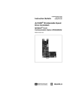
When a profile is implemented in a node, it is called a LonMark object.
A single node may implement multiple objects. The LonWorks module
implements two objects: one node object and one drive object. The
node object controls the drive object.
Objects within a node communicate with other network objects (in the
same or in other nodes) by exchanging network variables. Therefore,
to control and monitor the ATV58 TRX drive controller, the LonWorks
master must be programmed to read and write the network variables
supported by the module.
Network Variable Types
A network variable is an object on one node that can be connected to
one or more network variables on one or more additional nodes. A
node's network variables define its inputs and outputs from a network
point of view and allow the sharing of data in a distributed application.
When a program writes into one of its output network variables, the
new value of the network variable is propagated across the network
to all nodes with input network variables connected to that output
network variable.
For example, to turn on a light over a LonWorks network, a switch
node has its output network variable (nvoSwitch) connected or bound
to the input variable (nviSwitch) on the lamp node. When the switch
is activated, the network variable is propagated across the network
and received by the lamp node which turns on the light. The
LonWorks to MODBUS module uses two classes of network variable
types: Standard Network Variable Type (SNVT) and Standard
Configuration PropertiesType (SCPT).
SNVT (Standard Network Variable Type)
The LonMark organization has approved a number of network
variables that represent different types of standard data
representation; for example, drive speed, current, and voltage. These
network variables are called Standard Network Variable Types
(SNVTs) and are listed in the SNVT Master List and Programmers
Guide from Echelon Corporation. SNVTs contain information about
type, resolution, and range; they may be either nvi (network variable
inputs) or nvo (network variable outputs). The LonMark association
defines objects that can be described as a group of SNVTs used for
a specific application.
© 2001–2003 Schneider Electric All Rights Reserved
29
Section 5: LonWorks Configuration
The LonWorks Interface
VVDED300055USR11/03
11/2003
SCPT (Standard Configuration PropertiesType)
Configuration properties are used to store parameters that need to be
preserved in non-volatile memory. In the LonWorks to Modbus
module, Standard Configuration Properties Types (SCPTs) can be
implemented only as network variables. The network variables used
for parameters are defined to store the information in flash memory
onboard the LonWorks to Modbus module.
The specific objects and variables used by the LonWorks to Modbus
module are defined on the following pages. For more detail on ATV58
TRX drive controller configuration parameters, refer to the ATV58
TRX Keypad Display Instruction Bulletin, VVDED397047US.
Node Object
Node Object
nv0
nviObjRequest
SNVT_obj_request
Figure 5:
30
Mandatory
Network
Variables
nv1
nvoObjStatus
SNVT_obj_status
Node Object
© 2001–2003 Schneider Electric All Rights Reserved
VVDED300055USR11/03
11/2003
Table 4:
Parameter
Section 5: LonWorks Configuration
The LonWorks Interface
Node Object
Network Variable and Status
Function
network input
This input provides a way to request a particular
SNVT_obj_request nviObjRequest ‡ mode for a particular object within a node.
Node Object
Request
Node Object
Status
RQ_NORMAL *
If the object was in the disabled or overridden state,
this request cancels that state and returns the object
to normal operation.
RQ_UPDATE_STATUS *
The status of the object is sent to the output network
variable nvoObjStatus. The state of the object is
unchanged. The LonWorks master should issue this
request periodically to monitor the status of the
module. If any active status conditions are reported
through nvoObjStatus, this request should be
followed by RQ_CLEAR_STATUS so that a new
status condition can be reported.
RQ_REPORT_MASK *
The status bits that are supported by the object are
sent to the output network variable nvoObjStatus.
RQ_CLEAR_STATUS *
This input clears all object status bits.
network output
SNVT_obj_status nvoObjStatus ‡
Network variables of type SNVT_obj_status are used
to indicate the status of the various objects within a
node. This network variable provides the LonWorks
master the status of the node.
comm_failure *
If communication over the Modbus link goes down
this is reported by setting this bit in nvoObjStatus.
out_of_limits *
If a command value from the LonWorks master
Control Device is out of range for this register, it is
reported by setting this bit in nvoObjStatus.
‡
Variables used by the object.
*
Possible values of the variables.
© 2001–2003 Schneider Electric All Rights Reserved
31
Section 5: LonWorks Configuration
The LonWorks Interface
VVDED300055USR11/03
11/2003
Drive Object
Variable Speed Motor Drive: 6010
nv2
nviDrvSpeedStpt
SNVT_switch
Mandatory Network
Variables
nv5
nvoDrvSpeed
SNVT_lev_percent
nv3
nviDrvSpeedScale
SNVT_lev_percent
Optional Network
Variables
nv6
nvoDrvCurnt
SNVT_amp
Configuration
Properties
nv4
nv27 - nc23 - nciMinSpeed (mandatory)
nv28 - nc20 - nciMaxSpeed (mandatory)
nv29 - nc158 - nciNmlSpeed (mandatory)
nv30 - nc159 - nciNmlFreq (mandatory)
nv31 - nc160 - nciRampUpTm (mandatory)
nv32 - nc161 - nciRampDownTm (mandatory)
nviResetFault
SNVT_switch
Manufacturer
Defined
Network
Variables
nv40 - nc49 - nciSndHrtBt (mandatory)
nv41 - nc52 - nciMinOutTm (optional)
nv42 - nc48 - nciRcvHrtBt (optional)
nv43 - nc17 - nciLocation (optional)
nv44 - nc52 - nciDrvSpeedScale (optional)
nv7
nvoFreqOut
SNVT_freq_hz
nv8
nvoDrvPwr
SNVT_lev_percent
nv9
nvoTempInvrtr
SNVT_lev_percent
nv10
nvoMotorTorque
SNVT_lev_percent
nv11
nvoAl1Input
SNVT_volt
nv12
nvoAl2Input
SNVT_amp_mil
nv13
nvoAl3Input
SNVT_volt
nv14
nvoKWH
SNVT_count
Continued on the next page.
Figure 6:
32
Variables and Configuration Properties in Drive
Object
© 2001–2003 Schneider Electric All Rights Reserved
VVDED300055USR11/03
11/2003
Section 5: LonWorks Configuration
The LonWorks Interface
Continued from the previous page.
Manufacturer
Defined
Network
Variables
Manufacturer
Defined
Configuration
Properties
nv33 - SQD1 - nciEnergSave
nv34 - SQD2 - nciCntrlStop
nv35 - SQD3 - nciPlSetPoint
nv36 - SQD4 - nciPlProGain
© 2001–2003 Schneider Electric All Rights Reserved
nv15
nvoRunTimeHr
SNVT_count
nv16
nvoAlarmWord
SNVT_count
nv17
nvoAlarmWrd1
SNVT_count
nv18
nvoAlarmWrd2
SNVT_count
nv19
nvoAlarmWrd3
SNVT_count
nv20
nvoAlarmWrd4
SNVT_count
nv21
nvoAlarmWrd5
SNVT_count
nv22
nvoAlarmWrd6
SNVT_count
nv23
nvoAlarmWrd7
SNVT_count
nv24
nvoAlarmWrd8
SNVT_count
nv25
nvoStatusWord
SNVT_count
nv26
nvoDrvStatus
SNVT_count
nv37 - SQD5 - nciPlIntGain
nv38 - SQD6 - nciCurrLimit
nv39 - SQD7 - nciPlFeedBackScl
nv45 - SQD8 - nciAcceptAddress
33
Section 5: LonWorks Configuration
The LonWorks Interface
VVDED300055USR11/03
11/2003
Input Network Variables for Drive Control (nvi’s)
Table 5:
Parameter Variable Name
Drive
Speed
Setpoint
network input
SNVT_switch
nviDrvSpeedStpt
Drive Control Variables (nvi’s)
Function
This input network variable provides start/stop control and a lowresolution speed setpoint. When nviDrvSpeedStpt.State is set to zero
the drive is stopped.
SNVT default value:
Default value is AUTO (state: 0xFF). This value is adopted at powerup and in case of not receiving an update to nviDrvSpeedStpt or
nviDrvSpeedScale within receive heartbeat time (if used). This input
network variable may use the Receive Heartbeat (nciRcvHrtBt)
function depending on if Receive Heartbeat function is set-up for use.
The actual value of drive speed does also depend on settings of
nviDrvSpeedScale and nciNmlFreq.
Scaling: 0.5 x nviDrvSpeedStpt.Value up to 200 to get percent value.
If nviDrvSpeedStpt.Value is larger than 200 the percent value is
set to 100%.
nviDrvSpeedStpt.State: 0 = Stop command
nviDrvSpeedStpt.State: 1 = Run command
Valid Range of nviDrvSpeedStpt:
Drive
Speed
Setpoint
Scaling
Fault
Reset
34
State
Value
0
1
1
1
0xFF
N/A
0
1 to 200
201 to 255
N/A
Equivalent
Percent
N/A
0%
0.5 to 100%
100%
N/A
Requested
Speed
STOPPED
0%
0.5 to 100%
100%
AUTO (invalid)
network input
SNVT_lev_percent
nviDrvSpeedScale
This input network variable provides scaling for nviDrvSpeedStpt. For
example, if nviDrvSpeedStpt value is 100% and nviDrvSpeedScale
value is -150%, then actual speed setpoint value is -150% meaning
reverse 1.5 times nominal frequency. This input network variable may
use the Receive Heartbeat (nciRcvHrtBt) function depending on if
Receive Heartbeat function is set-up for use.
Valid Range: -163.840 to >163.830%
SNVT default value: defined by nciDrvSpeedScale.
If nviDrvSpeedScale ≥ 0: Normal direction
If nviDrvSpeedScale < 0: Reverse direction
network input
SNVT_switch
nviResetFault
This input network variable clears the fault in the drive, if the fault
condition is no longer present.
State: 0, Value: 0%, Command: no action
State: 1, Value: 100%, Command: reset fault
On a transition from 0 to 1, this input network variable clears the fault
condition in the drive. Following a reset, this variable must be set to 0
and sent to the module to enable the next reset.
SNVT default value: 0
NOTE: Only resettable faults are cleared. See the keypad manual,
VVDED397047US, for a list of resettable faults.
© 2001–2003 Schneider Electric All Rights Reserved
VVDED300055USR11/03
11/2003
Section 5: LonWorks Configuration
The LonWorks Interface
Input Network Configuration Properties for Drive Configuration (nci’s)
Table 6:
Drive Configuration Properties (nci’s)
Parameter Properties Name
Function
Low
Speed
Setpoint
network input config
SNVT_lev_percent
nciMinSpeed
This configuration property is used to define the minimum speed of a
motor. Its value is entered as a percent of nominal frequency, as
defined by the nominal frequency (nciNmlFreq) configuration value.
If nciNmlFreq = 60 Hz and nciMinSpeed = 10%, the minimum speed is
6 Hz.
The value of the minimum speed must be validated against the value
of the maximum speed as follows:
0% ≤ minimum speed ≤ maximum speed ≤ 163.830%
An incoming negative value in nciMinSpeed sets nciMinSpeed to 0
(zero).
Scaling: The value sent to the drive = 0.005 x nciMinSpeed x
nciNmlFreq.
Valid range: 0 to HSP (High Speed Setpoint)
High
Speed
Setpoint
network input config
SNVT_lev_percent
nciMaxSpeed
This configuration property is used to define the maximum speed of a
motor. It’s value is entered as a percent of nominal frequency, as
defined by the Nominal frequency (nciNmlFreq) configuration value.
If nciNmlFreq = 60 Hz and nciMaxSpeed = 120%, the maximum speed
is 72 Hz.
The value of the maximum speed must be validated against the value
of the minimum speed as follows:
0% ≤ minimum speed ≤ maximum speed ≤ 163.830%
Scaling: The value sent to the drive = 0.005 x nciMaxSpeed x
nciNmlFreq.
Valid range: LSP (Low Speed Setpoint) to TFR (Maximum Frequency)
Nominal
Motor
Speed
network input config
SNVT_rpm
nciNmlSpeed
This configuration property is used to enter the nominal speed of the
motor in RPM. Enter the value provided on the motor nameplate.
Valid range: 0 to 32767
network input config
SNVT_freq_hz
nciNmlFreq
This configuration property is used to provide the nominal frequency of
the motor in Hertz. This value is necessary to determine the minimum
and maximum speed for the motor, based on the configuration
properties nciMinSpeed, nciMaxSpeed (entered as percent of nominal
frequency).
Valid range: 10.0 to TFR (Maximum Frequency)
Nominal
Motor
Frequency
network input config
Acceleration
SNVT_time_sec
Time
nciRampUpTm
This configuration property is used to set the ramp up time.
Valid range: 0.05 to 999.9
network input config
Deceleration
SNVT_time_sec
Time
nciRampDownTm
This configuration property is used to set the ramp down time.
Valid range: 0.05 to 999.9
© 2001–2003 Schneider Electric All Rights Reserved
35
Section 5: LonWorks Configuration
The LonWorks Interface
Table 6:
Parameter Properties Name
VVDED300055USR11/03
11/2003
Drive Configuration Properties (nci’s) (continued)
Function
Energy
Saving
network input config
SNVT_switch
nciEnergSave
This configuration property enables the automatic energy savings
function in the drive controller. The drive controller must be set for VT
mode in the Macro-Configuration menu.
State: 0, Value: 0%, Command: no automatic energy saving function.
State: 1, Value: 100%, Command: energy saving function enabled.
Valid range: 0 to 1
Controlled
Stop
network input config
SNVT_count
nciCntrStop
This configuration property determines how the drive responds and
stops the motor in the event of a power loss.
Value: 0, Command: no controlled stop
Value: 1, Command: maintain DC bus
Value: 2, Command: follow ramp
Valid range: 0 to 2
PI Setpoint
network input config
SNVT_count
nciPISetPoint
Valid range: 0 to 10000
Note: For an adjustment to PI Setpoint to be valid, the ATV58 TRX
PI Regulator function must be enabled through Menu 5 of the keypad
display or the I/O menu in the test and commissioning software.
Connect the PI feedback signal to the analog input on the drive
controller terminal strip selected when the PI regulator function is
enabled.
PI
Proportional
Gain
network input config
SNVT_count
nciPIProGain
Valid range: 1 to 10000
Note: For an adjustment to PI Proportional Gain to be valid, the
ATV58 TRX PI Regulator function must be enabled through Menu 5 of
the keypad display or the I/O menu in the test and commissioning
software.
PI Integral
Gain
network input config
SNVT_count
nciPIIntGain
Valid range: 1 to 10000
Note: For an adjustment to PI Integral to be valid, the ATV58 TRX
PI Regulator function must be enabled through Menu 5 of the keypad
display or the I/O menu in the test and commissioning software.
network input config
PI Feedback
SNVT_lev_percent
Scale Factor
nciFeedBackScl
Scaling: The value sent to the drive = nciPIFeedBackScale / 20
Valid range: 10 to 1000
Note: For an adjustment to PI Scale Factor to be valid, the ATV58 TRX
PI Regulator function must be enabled through Menu 5 of the keypad
display or the I/O menu in the test and commissioning software.
Current
Limit
network input config
SNVT_amp
nciCurrLimit
Valid range: 10 to 136% of the drive constant torque output current
rating shown on the drive nameplate.
See Instruction Bulletin VVDED397047US, ATV58 TRX Keypad
Display, for further details on the drive current limit function.
Send
Heartbeat
Time
network input config
SNVT_time_sec
nciSndHrtBt
This input configuration network variable defines the maximum period
of time that expires before nvoDrvSpeed automatically updates.
If nciSndHrtBt is set to 0, the Send Heartbeat mechanism is disabled.
SNVT default value: 0 seconds
Valid range: 1–10 seconds
36
© 2001–2003 Schneider Electric All Rights Reserved
VVDED300055USR11/03
11/2003
Table 6:
Parameter Properties Name
Minimum
Send Time
Section 5: LonWorks Configuration
The LonWorks Interface
Drive Configuration Properties (nci’s) (continued)
Function
network input config
SNVT_time_sec
nciMinOutTm
This input configuration network variable controls the minimum period
of time that expires before the network output variables (nvo’s) can be
resent. This is good for limiting use of bandwidth on the LonWorks
channel.
If nciMinOutTm is set to 0, transmission limiting is disabled.
SNVT default value: 0
network input config
SNVT_time_sec
nciRcvHrtBt
This configuration property is used to control the maximum time that
elapses between updates to either nviDrvSpeedStpt or
nviDrvSpeedScale. If timeout occurs, the LonWorks module stops all
communication with the drive and nviDrvSpeedStpt and
nviDrvSpeedScale adopts their default values.
If nciRcvHrtBt is set to 0, the Receive Heartbeat mechanism is
disabled, and the motor will continue to run at its present speed when
communication with the LonWorks master is lost.
SNVT default value: 7 seconds
Minimum value allowed: 1 second
Receive
Heartbeat
Time
WARNING
LOSS OF CONTROL
If the Receive Heartbeat Time feature is disabled, provide another
means to control the drive, as recommended on page 19, when
communication is lost.
Failure to follow this instruction can result in death, serious
injury, or equipment damage.
Location
Label
network input config
SNVT_str_asc
nciLocation
This configuration property can optionally be used to provide more
descriptive physical location information than can be provided by the
neuron chip’s 6-byte location string. The location relates to the object
and not to the node.
Maximum number of ascii characters is 30 + NULL terminator.
SNVT default value: Filled up with NULL characters (“\0”).
Default
Value
network input config
SNVT_lev_percent
nciDrvSpeedScale
This parameter is used for setting default value to nviDrvSpeedScale
on every start-up.
SNVT default value: 0
Valid range: -163.84 to 163.83%
© 2001–2003 Schneider Electric All Rights Reserved
37
Section 5: LonWorks Configuration
The LonWorks Interface
Table 6:
Parameter Properties Name
VVDED300055USR11/03
11/2003
Drive Configuration Properties (nci’s) (continued)
Function
This parameter is used to identify which network master has control
over the drive. When this feature is enabled, the module accepts write
commands for nviDrvSpeedStpt and nviDrvSpeedScale only from the
specified LonWorks node.
Instead of a standard variable type (SNVT), this variable uses a
manufacturer-defined variable type UNVT_address, which is defined
as follows:
Authorized
Network
Master
network input config
UNVT_address
nciAcceptAddress
typedef struct
{
short unsigned subnet;
short unsigned node;
}
UNVT_address;
The high byte means SUBNET and the low byte means NODE#. The
function is disabled by writing 0 to both SUBNET or NODE. This
enables the drive to be controlled by any node on the network. The
function is activated when writing values to the nciAcceptAddress
variable as seen in this example:
If the master has address 10.12 (SUBNET = 10 and NODE = 12) then
10 should be written to the first byte (SUBNET) and 12 should be
written to the second byte (NODE) in nciAcceptAddress.
38
© 2001–2003 Schneider Electric All Rights Reserved
VVDED300055USR11/03
11/2003
Section 5: LonWorks Configuration
The LonWorks Interface
WARNING
LOSS OF CONTROL
Ensure that the module's Authorized Network Master is a valid host
control device at all times.
Failure to follow this instruction can result in death or serious
injury.
While a given LonWorks device is designated as the module's
Authorized Network Master, it is possible for another device to be
designated as the master. This allows devices such as a LonWorks
configuration tool to assume temporary control of the module's
operation. When the temporary controller's operations are finished,
the user must load the original LonWorks master address back into
the Authorized Network Master variable, so that the original master
can resume control of the module. If the new master device neither
controls the module nor returns control to the original master, the
module's response depends on its Receive Heartbeat setting:
• If the Receive Heartbeat feature is enabled, the module will
eventually detect a Receive Heartbeat Fault and stop
communications with the drive, which will in turn undergo a
communications time-out and stop the motor.
• If the Receive Heartbeat feature is disabled, the module will
continue to communicate with the drive, which will continue to
operate at its current speed and parameters settings.
In either case, when the original master attempts to write the Speed
Setpoint and/or Speed Scale parameter to the module, the module
will refuse the request, thus informing the original master that it might
not be the Authorized Network Master. The original master can verify
this by reading the module's Authorized Network Master variable. If
appropriate for the application, the original master can reclaim control
by writing its own address to the module's Authorized Network Master
variable.
To prevent an inappropriate device from being permanently
designated as the Authorized Network Master, the master can
periodically write its own address to the module's Authorized Network
Master variable.
© 2001–2003 Schneider Electric All Rights Reserved
39
Section 5: LonWorks Configuration
The LonWorks Interface
VVDED300055USR11/03
11/2003
Output Network Variables for Drive Feedback (nvo’s)
Table 7:
Drive Output Variables (nvo’s)
Parameter Variable Name
Function
network output
Drive Output
SNVT_level_percent
Speed
nvoDrvSpeed
This output network variable provides the speed of the drive
controller as a percentage of the nominal speed. This output
network variable is also periodically transmitted to the LonWorks
master, so that it serves as a heartbeat signal (at the rate specified
by nciSndHrtBt) to indicate the health of the LonWorks
communication interface.
Calculated as the rate in percent between the drive controller output
motor frequency and nciNmlFreq. For normal direction, this value is
positive; for reverse direction, the value is negative.
Value in nvoDrvSpeed = (drive controller output frequency applied
to motor ÷ nciNmlFreq) x 20000 to fit SNVT_lev_percent resolution.
Drive Output network output
Current
SNVT_amp nvoDrvCurnt
This output network variable provides the drive output current
in amperes.
Output
network output
Output frequency in Hz. Always positive, i.e. no information about
Frequency to
SNVT_freq_hz nvoFreqOut direction of revolution (forward/reverse)
Motor
network output
Drive Output
SNVT_lev_percent
Power
nvoDrvPwr
Scaling: the value in nvoDrvPwr = ATV58 TRX output power
measurement x 200 to fit SNVT_lev_percent resolution.
Drive
Thermal
State
network output
SNVT_lev_percent
nvoTempInvrtr
Scaling: the value in nvoTempInvrtr = drive thermal state
measurement x 200 to fit SNVT_lev_percent resolution.
Motor
Torque
network output
SNVT_lev_percent
nvoMotorTorque
Scaling: the value in nvoMotorTorque = drive calculated motor
torque x 200 to fit SNVT_lev_percent resolution.
Signal AI1
network output
Analog Input SNVT_volt nvoAI1Input
Scaling: the value in nvoAI1Input = (the signal measured at drive
analog input 1) / 100 to fit SNVT_volt resolution.
network output
Signal AI2
SNVT_amp_mil
Analog Input
nvoAI2Input
Scaling: the value in nvoAI2Input = (the signal measured at drive
analog input 2) / 50 to fit SNVT_amp_mil resolution.
Signal AI3
network output
Analog Input SNVT_volt nvoAI3Input
Scaling: the value in nvoAI3Input = (the signal measured at drive
analog input 3) / 100 to fit SNVT_volt resolution. This function is not
compatible with the encoder feedback signal available on the
VW3A58202 Digital I/O Extension Card, an option for the drive.
Drive
network output
Kilowatt Hour SNVT_count nvoKWH
Total kilowatt hours used since last reset through keypad parameter
RPR. This parameter is only available with drives equipped with
firmware version 4.0 and later.
Drive Run
Time
40
network output
SNVT_count
nvoRunTimeHr
Total run time in hours used since last reset through keypad
parameter RPR. This parameter is only available with drives
equipped with firmware version 4.0 and later.
© 2001–2003 Schneider Electric All Rights Reserved
VVDED300055USR11/03
11/2003
Table 8:
Fault
Section 5: LonWorks Configuration
The LonWorks Interface
Drive Fault Variables (nvo’s)
Variable Name and Function
Possible Values and Conditions
network output
SNVT_count nvoAlarmWord
Current This output register displays the currently active fault.
Fault
This register may only momentarily show an integer
value before the fault is recorded in the past fault
register.
Past
Fault 1
Past
Fault 2
Past
Fault 3
Past
Fault 4
Past
Fault 5
Past
Fault 6
Past
Fault 7
Past
Fault 8
‡
0 = : No fault saved
1 = : Internal fault
2 = : EEPROM memory fault
3 = : Configuration (parameters) incorrect
(initialization)
4 = : Configuration (parameters) invalid
network output
(if writing a configuration)
SNVT_count nvoAlarmWrd1
5 = : Standard communication link fault
This output register records the most recent fault. ‡
(link break)
network output
6 = : Fast communication link fault (link
SNVT_count nvoAlarmWrd2
break)
This output register records the second most recent
7 = : Fast communication “NET” fault
fault. ‡
8 = : External fault
9 = : Overcurrent fault (prolonged ICL)
network output
10 = : Precharge relay fault
SNVT_count nvoAlarmWrd3
This output register records the third most recent fault. ‡ 11 = : Loss of speed feedback fault
12 = : Ramp not followed
network output
13 = : Loss of follower fault
SNVT_count nvoAlarmWrd4
14 = : Thermal sensor fault
This output register records the fourth most recent
15 = : Motor overheating fault (thermal
fault. ‡
sensor)
network output
16 = : Drive controller overheating fault
SNVT_count nvoAlarmWrd5
(on heatsink)
This output register records the fifth most recent fault. ‡ 17 = : Motor overload fault (thermal
simulation or thermal sensor)
network output
18 = : DC bus overvoltage fault
SNVT_count nvoAlarmWrd6
This output register records the sixth most recent fault. ‡ 19 = : Input supply overvoltage fault
20 = : Motor phase failure fault
network output
21 = : Input supply phase failure fault (> 1 s)
SNVT_count nvoAlarmWrd7
22 = : Input supply undervoltage fault
This output register records the seventh most recent
(> 200 ms)
fault. ‡
23 = : Motor short circuit fault (phase to earth)
network output SNVT_count nvoAlarmWrd8
24 = : Overspeed fault (with speed feedback:
This output register records the eighth most recent
1.11 x HSP; without feedback: 1.2 x TFR)
fault. ‡
The integer value in the register indicates the fault condition.
© 2001–2003 Schneider Electric All Rights Reserved
41
Section 5: LonWorks Configuration
The LonWorks Interface
Table 9:
VVDED300055USR11/03
11/2003
Drive Status 1 Variables (nvo’s)
Variable Name and Function
Possible Values and Condition
network output SNVT_count nvoStatusWord
Bit 0 = 0: Power not ready
Bit 0 = 1: Power ready for startup
This output register indicates various internal
drive states.
Bit 1 = 0: Drive controller not ready
Bit 1 = 1: Drive controller ready
Bit 2 = 0: DRIVECOM stop
Bit 2 = 1: DRIVECOM run
Bit 3 = 0: No fault
Bit 3 = 1: Fault present
Bit 4 = 0: Power present
Bit 4 = 1: Power not present
Bit 5 = 0: Fast stop in progress
Bit 5 = 1: No fast stop
Bit 6 = 0: Status = OUTPUT SWITCHING DISABLED
Bit 6 = 1: Status = OUTPUT SWITCHING DISABLED
(freewheel stop)
Bit 7 = 0: Alarm absent
Bit 7 = 1: Alarm present
Bit 8 = 1: Reserved
Bit 9 = 0: Local forcing in progress
Bit 9 = 1: No local forcing
Bit 10 = 0: Reference not reached (transient state)
Bit 10 = 1: Reference reached (steady state)
Bit 11 = 0: LFRD reference normal
Bit 11 = 1: LFRD reference exceeded (> HSP or < LSP)
Bits 12 and 13: Reserved
Bit 14 = 0: No stop from keypad STOP key
Bit 14 = 1: Stop from keypad STOP key
Bit 15 = 0: Forward direction of rotation (output frequency)
Bit 15 = 1: Reverse direction of rotation (output frequency)
42
© 2001–2003 Schneider Electric All Rights Reserved
VVDED300055USR11/03
11/2003
Table 10:
Section 5: LonWorks Configuration
The LonWorks Interface
Drive Status 2 Variables (nvo’s)
Variable Name and Function
Possible Values and Condition
Bit 0 = 0: Write parameters authorized
Bit 0 = 1: Write parameters not authorized (EEPROM saving in
This output register indicates various internal progress)
drive states.
Bit 1 = 0: No parameter consistency check, drive controller locked
network output SNVT_count nvoDrvStatus
at stop
Bit 1 = 1: Parameter consistency check
Bit 2 = 0: Clear fault not authorized
Bit 2 = 1: Clear fault authorized
Bit 3: Reserved
Bit 4 = 0: Motor stopped
Bit 4 = 1: Motor running
Bit 5 = 0: No DC injection
Bit 5 = 1: DC injection
Bit 6 = 0: Drive controller in steady state
Bit 6 = 1: Drive controller in transient state
Bit 7 = 0: No thermal overload alarm
Bit 7 = 1: Thermal overload alarm
Bit 8 = 0: No alarm if excessive braking
Bit 8 = 1: Alarm if excessive braking
Bit 9 = 0: Drive controller not accelerating
Bit 9 = 1: Drive controller accelerating
Bit 10 = 0: Drive controller not decelerating
Bit 10 = 1: Drive controller decelerating
Bit 11 = 0: No current limit alarm
Bit 11 = 1: Current limit alarm
Bit 12: Reserved
Bit 14 = 0, Bit 13 = 0: Drive controlled via terminals
Bit 14 = 0, Bit 13 = 1: Drive controlled via keypad display
Bit 14 = 1, Bit 13 = 0: Drive controlled via keypad Modbus port
Bit 14 = 1, Bit 13 = 1: Drive controlled via Modbus option card
Bit 15 = 0: Forward direction of rotation requested (reference)
Bit 15 = 1: Reverse direction of rotation requested (reference)
© 2001–2003 Schneider Electric All Rights Reserved
43
Section 6: Minimum Startup Procedure
Minimum Startup Procedure
VVDED300055USR11/03
11/2003
SECTION 6: MINIMUM STARTUP PROCEDURE
MINIMUM STARTUP PROCEDURE
The minimum requirements to command the drive controller from the
LonWorks network:
1. Ensure that a LonWorks network master is installed and operating
and that the network cable has been run out to the ATV58 TRX
drive controller location.
2. Install the supplied External Interface File (XIF) and Device
Resource Files.
3. Mount the LonWorks module to a grounded DIN rail close enough
to the ATV58 TRX drive to allow the 29.5 in (750 mm) Modbus
cable to extend between the Modbus ports on the module and the
drive Modbus port without straining either the cable or port
connections. Refer to “LonWorks Module” on page 15.
4. Wire an appropriately sized 24 Vdc power supply into the module
power supply connector (observe polarity). Refer to “24 Vdc
Power Supply” on page 16.
5. Connect the LonWorks network cable to the LonWorks module.
Refer to “Electrical Wiring” on page 16.
6. Wire the selector switch to the ATV58 TRX drive control terminal
block. Refer to Figures 3 and 4 on page 20.
7. Determine if the keypad display will be normally mounted on the
drive controller.
If the keypad display is not normally mounted to the drive (see
“Keypad Modbus Port” on page 22):
— Connect an ATV58 TRX programming tool to the keypad
Modbus port. Apply power to the drive. Make the needed
configuration changes to the drive, including communication
parameters and the “forced local” function.
— Remove power from the drive. Follow the Bus Voltage
Measurement Procedure to ensure it is safe to remove the
ATV58 TRX programming tool.
— Install the interconnecting Modbus cable between the
LonWorks module and the keypad port.
— Reapply power to the drive.
44
© 2001–2003 Schneider Electric All Rights Reserved
VVDED300055USR11/03
11/2003
Section 6: Minimum Startup Procedure
Minimum Startup Procedure
If the keypad display is normally mounted on the drive (see
“Modbus Option Card” on page 22):
— Install the Modbus option card (VW3A58303U) into the drive.
On the Modbus card, set the address switches for an address
of 1 and set the configuration switches for Modbus operation.
— Install the interconnecting Modbus cable between the
LonWorks module and the port on the Modbus option card.
— With the keypad display installed, apply power to the drive
controller. Make the necessary configuration changes to the
drive, including communication parameters and the “forced
local” function.
8. Apply power to the LonWorks module.
9. Install/Commission the ATV58 TRX drive node using a LonWorks
network management tool.
10. Configure the ATV58 TRX drive node using the LonWorks
network management tool. This includes pressing the service pin
on the module.
11. Use the Drive Speed Setpoint and Drive Speed Setpoint Scaling
SNVT's to start the drive and supply it with a speed reference.
© 2001–2003 Schneider Electric All Rights Reserved
45
Section 7: Diagnostics
LED States
VVDED300055USR11/03
11/2003
SECTION 7: DIAGNOSTICS
LED STATES
The LonWorks module has four diagnostic LEDs that indicate the
status of the module and the communication link with the drive and
the LonWorks network (see Figure 1 on page 12). Table 11 shows the
LED states, what they indicate, and suggested corrective actions.
Table 11:
LED
LED Status Indicators
LED Color
Function
Solid green
Modbus communication okay No action
Solid red
(or off longer
Hardware error
than 4 seconds)
Module
Status
Serial communication error
(Modbus link to drive not
initialized or time-out on
Modbus communication.)
Flashing red
(2 times per
second)
Check the connection to the LonWorks network.
Ensure that the LonWorks master is operating
Heartbeat variable not
properly.
detected, no communication
Ensure that the LonWorks master is sending
with LonWorks master.
Drive Speed Setpoint and Drive Speed Scaling in
the required amount of time.
Flashing green
This node has an application
The module is ready to be installed with an
but is not yet installed in a
installation tool.
network (unconfigured).
Turned off
This node is configured and
installed in a network.
No action
Solid green
This node is unconfigured
and applicationless.
Try to reset the module to configured by
unconfiguring with the installation tool. If not
possible, there is an internal error in the module.
Flashing red
(alternates slow The node has received a
and fast for
LonWorks Wink command.
20 seconds)
Solid green
LonWorks
Status
46
Cycle 24 Vdc power on the module. Replace the
module if the LED is still lit after next power-up.
Flashing red
(8 times per
second)
Service
Wink
Action
Check the connections to the drive controller.
The module will continue trying to communicate
with the drive controller.
This command is sent from an installation tool
when visual identification of the module is
desired.
Power on
No action
Flashing red
(4 times per
second)
Recoverable error
It is possible that module will recover from this
error by itself. Check LonWorks network wiring.
Cycle 24 Vdc power on the module.
Solid red
Unrecoverable error
The module will not recover from this error by
itself. Cycle 24 Vdc power on the module.
Replace the module if the LED continues to be
solid red after cycling power.
© 2001–2003 Schneider Electric All Rights Reserved
VVDED300055USR11/03
11/2003
Section 7: Diagnostics
Troubleshooting
TROUBLESHOOTING
What will module do if it loses contact with the LonWorks network?
This occurs when the module can no longer detect the heartbeat
variable on LonWorks network. When the SNVT specified for
receive heartbeat (nciRcvHrtBt) is not updated within the
maximum time allowed since the last update, the module will
assume a LonWorks network failure. The module will stop all
communication with the drive and the error will be indicated by the
module status LED flashing red 2 times per second. The module
will remain in this state until an update to either nviDrvSpeedStpt
or nviDrvSpeedScale is received from the Master Control Device.
When LonWorks communication has been reestablished, the
module will resume normal operation and the module status LED
will be set to solid green.
What will the module do if it loses communication with the
ATV58 TRX drive?
If there is no response to Modbus messages sent to the drive or if
the responses indicate too many errors, the module status LED
will indicate the error by flashing red 8 times per second. The
module will report the loss of drive controller communication to the
LonWorks Master Control Device by use of the SNVT
nvoObjStatus. All other nvo values will be set to zero.
Communication with the Master Control Device will continue. The
module will keep trying to reestablish Modbus communication with
the drive. If it succeeds, the module status LED will be set to solid
green and the program will resume normal operation.
What will happen if there is an internal problem with the module?
If there is an internal problem in the module, it will suspend all
LonWorks and Modbus communication. Depending on the type of
internal problem, either the module status LED will be lit red
continuously or the LonWorks status LED will be red (either solid
or flashing).
What will happen if the 24 Vdc supply goes out of specification?
The module has a specified operating range of 19.2 Vdc to
28.8 Vdc. Above 30 Vdc, a transient diode will start conduct and
the module will not work until the power supply is brought within
the specified range again. The module's operation is unreliable
with an input voltage below 19.2 Vdc.
© 2001–2003 Schneider Electric All Rights Reserved
47
LonWorks to Modbus Module
Instruction Bulletin
Schneider Electric
8001 Highway 64 East
Knightdale, NC 27545
1-888-SquareD (1-888-778-2733)
www.SquareD.com
Electrical equipment should be installed, operated, serviced, and
maintained only by qualified personnel. No responsibility is assumed
by Schneider Electric for any consequences arising out of the use of
this material.
VVDED300055USR11/03
© 2001–2003 Schneider Electric All Rights Reserved
Replaces VVDED300055NA 12/2002
11/2003