1
INSTRUCTION MANUAL
VHF FM TRANSCEIVER
TK-6110
KENWOOD CORPORATION
© B62-1216-00 (K,K2)
09 08 07 06 05 04 03 02 01 00
THANK YOU!
We are grateful you chose KENWOOD for your land mobile applications. We
believe this easy-to-use transceiver will provide dependable communications to
keep personnel operating at peak efficiency.
KENWOOD transceivers incorporate the latest in advanced technology. As a
result, we feel strongly that you will be pleased with the quality and features of
this product.
NOTICES TO THE USER
◆
GOVERNMENT LAW PROHIBITS THE OPERATION OF UNLICENSED RADIO
TRANSMITTERS WITHIN THE TERRITORIES UNDER GOVERNMENT CONTROL.
◆
◆
ILLEGAL OPERATION IS PUNISHABLE BY FINE OR IMPRISONMENT OR BOTH.
REFER SERVICE TO QUALIFIED TECHNICIANS ONLY.
SAFETY: It is important that the operator is aware of, and understands, hazards
common to the operation of any transceiver.
WARNING!
◆ EXPLOSIVE ATMOSPHERES (GASES, DUST, FUMES, etc.)
Turn OFF your transceiver while taking on fuel or while parked in a gasoline service station. Do
not carry spare fuel containers in the trunk of your vehicle if your transceiver is mounted in the
trunk area.
◆ INJURY FROM RADIO FREQUENCY TRANSMISSIONS
Do not operate your transceiver when somebody is within two to three feet of the antenna, to
avoid the possibility of radio frequency burns or related physical injury.
◆ DYNAMITE BLASTING CAPS
Turn OFF your transceiver when in an area where blasting is in progress, or where “TURN OFF
TWO-WAY RADIO” signs have been posted. Operating the transceiver within 150 meters
(500 feet) of dynamite blasting caps may cause them to explode. If you are carrying blasting
caps in your vehicle, make sure they are enclosed in a metal box with a padded interior. Do not
transmit while the caps are being placed into or are being removed from the container.
Note: This instruction manual covers only the basic functions of the transceiver. Consult your dealer
for more detailed information.
One or more of the following statements may be applicable:
FCC WARNING
This equipment generates or uses radio frequency energy. Changes or modifications to this
equipment may cause harmful interference unless the modifications are expressly approved in the
instruction manual. The user could lose the authority to operate this equipment if an unauthorized
change or modification is made.
INFORMATION TO THE DIGITAL DEVICE USER REQUIRED BY THE FCC
This equipment has been tested and found to comply with the limits for a Class B digital device,
pursuant to Part 15 of the FCC Rules. These limits are designed to provide reasonable protection
against harmful interference in a residential installation. This equipment generates, uses and can
generate radio frequency energy and, if not installed and used in accordance with the instructions,
may cause harmful interference to radio communications. However, there is no guarantee that the
interference will not occur in a particular installation. If this equipment does cause harmful
interference to radio or television reception, which can be determined by turning the equipment off
and on, the user is encouraged to try to correct the interference by one or more of the following
measures:
• Reorient or relocate the receiving antenna.
• Increase the separation between the equipment and receiver.
• Connect the equipment to an outlet on a circuit different from that to which the receiver is
connected.
• Consult the dealer for technical assistance.
i
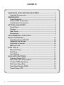
CONTENTS
UNPACKING AND CHECKING EQUIPMENT ................................... 1
Supplied Accessories ................................................................. 1
PREPARATION .................................................................................. 2
Tools Required ............................................................................. 2
Power Cable Connection ............................................................ 2
Installing the Transceiver ........................................................... 3
GETTING ACQUAINTED ................................................................... 4
Front Panel ................................................................................... 4
Display .......................................................................................... 5
Rear Panel .................................................................................... 6
Microphone .................................................................................. 6
PROGRAMMABLE FUNCTIONS ...................................................... 7
BASIC OPERATIONS ...................................................................... 10
Switching Power ON/ OFF ........................................................ 10
Adjusting the Volume ................................................................ 10
Selecting a Channel ................................................................... 10
Making a Call .............................................................................. 10
DTMF CALLS ....................................................................................11
Manual Dialing ............................................................................ 11
Redialing ...................................................................................... 11
Auto Dialing ................................................................................. 11
AUXILIARY FUNCTIONS ................................................................. 13
Time-out Timer (TOT) ................................................................ 13
Busy Channel Lockout (BCL) ................................................... 13
2-Tone/ DTMF Signaling ............................................................ 13
Roll Over/ Dead End .................................................................. 13
Dead Beat Disable (DBD) .......................................................... 14
Timed Power OFF ...................................................................... 14
ii
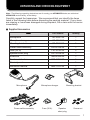
UNPACKING AND CHECKING EQUIPMENT
Note: The following unpacking instructions are for use by your KENWOOD dealer, an authorized
KENWOOD service facility, or the factory.
Carefully unpack the transceiver. We recommend that you identify the items
listed in the following table before discarding the packing material. If any items
are missing or have been damaged during shipment, file a claim with the carrier
immediately.
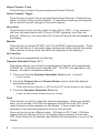
■ Supplied Accessories
Item
Part Number
Quantity
Microphone
T91-0597-X5
1
Microphone hanger
J19-1584-X5
1
Mounting bracket
J29-0662-X3
1
Power cable assembly
E30-3339-X5
1
Fuse (20 A)
F51-0018-X5
2
Speaker short plug
E31-3228-X5
1
Screw set
N99-0395-X5
1
Caution addendum
B59-1653-XX
1
––
1
B62-1216-XX
1
Warranty card
Instruction manual
Microphone
Power cable assembly
Microphone hanger
Fuse (20 A)
Mounting bracket
Speaker
short plug
Screw set
1
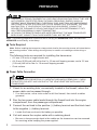
PREPARATION
◆ VARIOUS ELECTRONIC EQUIPMENT IN YOUR VEHICLE MAY MALFUNCTION IF THEY ARE
NOT PROPERLY PROTECTED FROM THE RADIO FREQUENCY ENERGY WHICH IS
PRESENT WHILE TRANSMITTING. ELECTRONIC FUEL INJECTION, ANTI-SKID BRAKING,
AND CRUISE CONTROL SYSTEMS ARE TYPICAL EXAMPLES OF EQUIPMENT THAT MAY
MALFUNCTION. IF YOUR VEHICLE CONTAINS SUCH EQUIPMENT, CONSULT THE
DEALER FOR THE MAKE OF VEHICLE AND ENLIST HIS AID IN DETERMINING IF THEY
WILL PERFORM NORMALLY WHILE TRANSMITTING.
◆ ALTHOUGH THE REMOTE PANELS ARE WATER RESISTANT, THE MAIN TRANSCEIVER
BODY IS NOT. MOUNT IT IN A PLACE WHERE IT WILL NOT GET WET.
Note: The following preparation instructions are for use by your KENWOOD dealer, an authorized
KENWOOD service facility, or the factory.
■ Tools Required
Note: Before installing the transceiver, always check how far the mounting screws will extend below
the mounting surface. When drilling mounting holes, be careful not to damage vehicle wiring or
parts.
The following tools are required for installing the transceiver:
• A 6 mm (1/4 inch) or larger electric drill.
• A 4.2 mm (5/32 inch) drill bit for the 5 x 16 mm self-tapping screws, and a 3.2 mm
(1/8 inch) drill bit for the 4 x 16 mm self-tapping screws.
• Circle cutters.
■ Power Cable Connection
THE TRANSCEIVER OPERATES IN 12 V NEGATIVE GROUND SYSTEMS ONLY! CHECK
THE BATTERY POLARITY AND VOLTAGE OF THE VEHICLE BEFORE INSTALLING THE
TRANSCEIVER.
1 Check for an existing hole, conveniently located in the firewall, where the
power cable can be passed through.
• If no hole exists, use a circle cutter to drill the firewall, then install a rubber
grommet.
2 Run the two power cable leads through the firewall and into the engine
compartment, from the passenger compartment.
3 Connect the red lead to the positive (+) battery terminal and the black lead
to the negative (–) battery terminal.
• Locate the fuse as close to the battery as possible.
4 Coil and secure the surplus cable with a retaining band.
• Be sure to leave enough slack in the cables so the transceiver can be removed
for servicing while keeping the power applied.
2
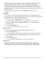
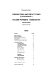
■ Installing the Transceiver
FOR PASSENGER SAFETY, INSTALL THE TRANSCEIVER SECURELY, USING THE
SUPPLIED MOUNTING BRACKET, SO THE TRANSCEIVER WILL NOT BREAK LOOSE IN
THE EVENT OF A COLLISION.
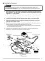
1 Mark the position of the holes in the dash by using the mounting bracket
as a template. Drill the holes, then attach the mounting bracket using the
supplied 5 x 16 mm screws.
• Be sure to mount the transceiver in a location where the controls will be within
easy reach of the user and where there is sufficient space at the rear of the
transceiver for cable connections.
2 Connect the antenna and the supplied power cable to the transceiver.
3 Slide the transceiver into the mounting bracket and secure it using the
supplied hex-headed screws.
4 Mount the microphone hanger, using the supplied 4 x 16 mm screws, in a
location where it will be within easy reach of the user.
• The microphone should be mounted in a place where it will not interfere with
the safe operation of the vehicle.
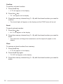
5 Connect the microphone cable to the jack on the front panel of the
transceiver. Place the microphone on the hanger.
Microphone
Microphone
hanger
Microphone cable
Mounting bracket
Transceiver
Hex headed
screw
Power input
connector
Antenna
connector
Fuse
Power cable
Fuse holder
Red wire
Battery
Black wire
3
GETTING ACQUAINTED
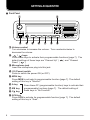
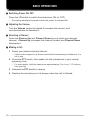
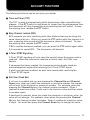
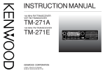
■ Front Panel
q
e
w
r
MON
A
t
y
B
C
u
i
SCN
o
q Volume control
Turn clockwise to increase the volume. Turn counterclockwise to
decrease the volume.
w
/
keys
Press these keys to activate their programmable functions {page 7}. The
default settings of these keys are “Channel Up” (
) and “Channel
Down” (
).
e Microphone jack
Insert the microphone plug into this jack.
r I O (Power) switch
Press to switch the power ON (or OFF).
t MON key
Press MON to activate its programmable function {page 7}. The default
setting of this key is “Monitor”.
y A key
u B▼ key
i C▲ key
Press these PF (programmable function) keys to activate their
programmable functions {page 7}. The default setting of
these keys is “No Function”.
o SCN key
Press SCN to activate its programmable function {page 7}. The default
setting of this key is “Scan”.
4
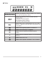
■ Display
Displays the operating Channel number, the Channel
name, and the transceiver status.
Displays the operating channel number and the
channel status:
P indicates a Priority channel
HC indicates a Home Channel
tA indicates Talk Around mode
Flashes when a call is received by DTMF or 2-Tone
signaling. Appears during and after transmitting if set
by the dealer.
Appears when signaling squelch is turned OFF.
Appears while scanning is in progress.
Appears when the optional scrambler board is
enabled.
Appears when the selected channel is in the scanning
sequence.
Appears when Aux is ON.
Appears when Operator Selectable Tone is enabled.
5
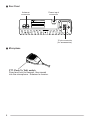
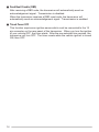
■ Rear Panel
Power input
connector
Antenna
connector
TK-6110
15 pin connector
(for accessories)
■ Microphone
PTT (Push To Talk) switch
Press and hold to transmit, then speak
into the microphone. Release to receive.
6
PROGRAMMABLE FUNCTIONS
The following functions can be programmed onto the
,
, MON, A, B▼,
C▲, and SCN keys. Contact your dealer for details on these functions.
AUX
Press this key to turn the Aux output port ON (or OFF). When you press this
key, the AUX icon appears and a tone sounds. When you press this key
again, the icon disappears and a tone sounds.
CH 1 Direct/ CH 2 Direct/ CH 3 Direct/ CH 4 Direct/ CH 5 Direct
Press these keys to directly select the Channel 1, Channel 2, Channel 3,
Channel 4, or Channel 5 directory (respectively).
Channel Down
Press this key decrease the channel number by 1 step. Press and hold this
key to scroll down through the channels.
Channel Name
Press this key to switch the display between the Channel number and name
(alphanumeric). A tone will sound each time you press this key.
Channel Up
Press this key increase the channel number by 1 step. Press and hold this
key to scroll up through the channels.
Delete/ Add
Press this key to delete a channel from, or add a channel to, the scanning
sequence. If a channel is already added to the scanning sequence, and you
want to delete it, press this key while the channel is displayed. The channel
add icon disappears. If a channel is not added to the scanning sequence,
and you want to add it, press this key while the channel is displayed. The
channel add icon appears.
Press this key while scanning, when an undesired channel is displayed, to
temporarily delete it from scan. If there are only 2 channels in the scanning
sequence, this function cannot be performed. To restore the original scanning
sequence, turn the scan function or the transceiver OFF, then ON.
Emergency Call
Press this key to initiate an emergency call (requires the ANI board). When
an emergency call is made, no tone is emitted and the display does not
change. To end the emergency call, turn the transceiver power OFF.
7
Home Channel: Fixed
Press this key to select the pre-programmed Home Channel.
Home Channel: Toggle
Press this key to select the pre-programmed Home Channel. Press this key
again to return to the previous channel. If used while scanning, pressing this
key a second time will change to the revert channel.
Horn Alert
Press this key to turn the Horn Alert function ON (or OFF). If you receive a
call from the base station with 2-Tone or DTMF signaling, Horn Alert will
activate. When you turn Horn Alert ON, a tone will sound and HA appears on
the display.
Monitor
Press this key to cancel QT/DQT and 2-Tone/DTMF signaling squelch. Press
and hold this key for 2 seconds to hear background noise (unmute the audio).
When monitor is being used, the MON icon appears on the display.o
No Function
No function is programmed onto the key.
Operator Selectable Tone (OST)
This feature allows you to select a signaling tone from the pre-programmed
QT/DQT list. Press this key to activate OST. The OST icon appears on the
display. To select a decode/encode pair:
1 Press and hold the Operator Selectable Tone key for 1 second.
• A tone sounds.
2 Press the Channel Up and Channel Down keys to select the desired
decode/encode pair.
• TONE and the tone number, or OST and the OST name appear on the display.
3 Press the Operator Selectable Tone key.
• A tone sounds and the display returns to normal.
Scan
Press this key to start (or stop) the scanning sequence. When you activate
scan, a tone sounds, the SCN icon appears, and SCAN or the OFF Hook
revert channel number appears on the display. If there is less than 2
channels in the scanning sequence, an error tone sounds.
Scan can be set up two different ways: ON Hook or OFF Hook. ON Hook
requires the microphone to be on its hanger before scanning will activate.
OFF Hook allows you to activate scan whether the microphone is on or off the
hanger.
8
When a signal is received while scanning, scanning will halt, the audio will
unmute, and the channel number or name will appear on the display.
If Priority is programmed, the priority channel is periodically checked for a
signal while a signal is being received on a normal channel. When a signal
appears on the priority channel, the transceiver will automatically switch to the
priority channel.
To enter carrier squelch scan, press the Monitor key while scan is in
progress.
Scrambler
If you have an optional scrambler board installed, you can press this key to
turn it ON (or OFF). When enabled, a tone sounds and the OPT icon appears
on the display. To change the scrambler code:
1 Press and hold the Scrambler key for 1 second.
• A tone sounds and CODE appears on the display with the current code.
2 Press the Channel Up and Channel Down keys to select the desired
scrambler code.
3 Press the Scrambler key.
• A tone sounds and the display returns to normal.
Squelch Level
You can manually adjust the squelch level using this function:
1 Press the Squelch key.
• A tone sounds and SQL appears on the display with the current squelch level.
2 Press the Channel Up and Channel Down keys to select the desired
squelch level.
3 Press the Squelch key.
• A tone sounds and the display returns to the normal channel.
Talk Around
Press this key to make a call without the use of a repeater. When you
activate this function, a tone sounds and tA appears on the 3-digit display.
This function is useful when you are close to the units you want to talk to.
9
BASIC OPERATIONS
■ Switching Power ON/ OFF
Press the I O switch to switch the transceiver ON (or OFF)
• The display backlight illuminates when the power is switched ON.
■ Adjusting the Volume
Turn the Volume control clockwise to increase the volume, and
counterclockwise to decrease it.
■ Selecting a Channel
Press the Channel Up and Channel Down keys to select your desired
channel. Channel Up increases the channel number and Channel Down
decreases it.
■ Making a Call
1 Select your desired channel (above).
• Listen to the channel for a few seconds before transmitting to make sure it is
not in use.
2 Press the PTT switch, then speak into the microphone in your normal
speaking voice.
• For best results, hold the transceiver approximately 3 to 4 cm (1 1/2 inches)
from your lips.
3 Release the PTT switch to receive.
4 Replace the microphone on its hanger when the call is finished.
10
DTMF CALLS
You can make DTMF calls using the optional KMC-28A DTMF microphone.
■ Manual Dialing
To dial a number manually:
1 Press and hold the PTT switch.
• If Keypad Auto PTT is enable, you do not need to press the PTT switch (please
consult your dealer for enabling this function).
2 Enter your desired digits.
■ Redialing
A maximum of 16 digits can be redialed. The last number dialed, either
manually or automatically, will be redialed.
To redial a number:
1 Press the
key.
• An “A” will appear on the display.
2 Press the 0 key.
• The transceiver will redial the last dialed number, and the digits will appear on
the display.
Note: If the transceiver power is switched OFF, the redial memory will be erased.
■ Auto Dialing
Note: Auto dialing is either enabled or disabled by your dealer.
Store:
To store a number in memory:
1 Press the # key.
• A “D” will appear on the display.
2 Enter up to a maximum of 16 digits.
• To enter A, B, C, D, , or #, press and hold the PTT switch, then press 2, 5, 8,
0, , or # (respectively).
3 Press the # key.
4 Select the desired memory channel by pressing a key (1 ~ 9).
• The number entered in step 2 will be stored in the memory channel selected.
11
Confirm:
To confirm a stored number:
1 Press the # key.
• A “D” will appear on the display.
2 Press the
key.
• “D–” will appear on the display.
3 Press the memory channel key (1 ~ 9) with the stored number you want to
confirm.
• The stored digits will appear on the display and the DTMF tones will sound.
Send:
To send a stored number:
1 Press the
key.
• An “A” will appear on the display.
2 Press the memory channel key (1 ~ 9) with the stored number you want to
send.
• The transceiver will begin the transmission and the digits will appear on the
display.
Clear:
To remove a stored number from memory:
1 Press the # key.
• A “D” will appear on the display.
2 Press the # key again.
• “D–CLR” will appear on the display.
3 Press the memory channel key (1 ~ 9) with the stored number you want to
erase.
12
AUXILIARY FUNCTIONS
The following functions can be set up by your dealer.
■ Time-out Timer (TOT)
The TOT is used to automatically inhibit transmission after a specified time
elapses. If the PTT switch is held down for longer than the programmed time,
the transceiver will stop transmitting and a warning tone will sound. To stop
the warning tone, release the PTT switch.
■ Busy Channel Lockout (BCL)
BCL prevents you from interfering with other stations that may be using the
same channel as you. When you press the PTT switch while the channel is in
use, a warning tone sounds and the transceiver does not transmit. To stop
the warning tone, release the PTT switch.
If BCL override has been enabled, you can press the PTT switch again within
0.5 seconds to cancel BCL. The transceiver will transmit.
■ 2-Tone/ DTMF Signaling
2-Tone/ DTMF signaling will only open the squelch when the proper code is
received. When the transceiver receives a correct code, the CALL icon
flashes.
If transpond has been enabled, the transceiver automatically sends an
acknowledgement signal after receiving the 2-Tone/ DTMF signal.
If alert tone has been enabled, an alert tone sounds after receiving the
2-Tone/ DTMF signal.
■ Roll Over/ Dead End
If roll over is enabled and you are pressing the Channel Up and Channel
Down keys, when you reach the maximum or minimum number, the number
will roll over to the minimum or maximum number. For example, when the
pressing the Channel Up key, the channel number increases. When it
reaches its maximum value, it rolls over to its minimum value and then starts
to increase again.
If dead end is selected, when you reach the maximum or minimum value, the
value will not change. For example, when when the pressing the Channel
Up key, the channel number increases. When it reaches its maximum value,
it stops. You must then press the Channel Down key to change the value.
13
■ Dead Beat Disable (DBD)
After receiving a DBD code, the transceiver will automatically send an
acknowledgement signal. Transmission is disabled.
When the transceiver receives a DBD reset code, the transceiver will
automatically send an acknowledgement signal. Transmission is enabled.
■ Timed Power OFF
This function requires an ignition-sense which must be connected to the 15
pin connector on the rear panel of the transceiver. When you turn the ignition
of your vehicle OFF, the timer starts. After the pre-selected time expires, the
transceiver will turn OFF. The timer resets when the vehicle ignition is turned
ON, then OFF.
14