1
TK-2212/ TK-3212
VHF FM TRANSCEIVER/
UHF FM TRANSCEIVER
INSTRUCTION MANUAL
ÉMETTEUR-RÉCEPTEUR FM VHF/
ÉMETTEUR-RÉCEPTEUR FM UHF
MODE D’EMPLOI
TRANSCEPTOR DE FM VHF/
TRANSCEPTOR DE FM UHF
MANUAL DE INSTRUCCIONES
© B62-1817-00 (K, K2, M, M2)
09 08 07 06 05 04 03 02 01 00
TK-2212/ TK-3212
INSTRUCTION MANUAL
ENGLISH
VHF FM TRANSCEIVER/
UHF FM TRANSCEIVER
THANK YOU
We are grateful you chose KENWOOD for your land mobile
radio applications. We believe this easy-to-use transceiver
will provide dependable communications to keep personnel
operating at peak efficiency.
KENWOOD transceivers incorporate the latest in advanced
technology. As a result, we feel strongly that you will be
pleased with the quality and features of this product.
MODELS COVERED BY THIS MANUAL
• TK-2212: VHF FM Transceiver
• TK-3212: UHF FM Transceiver
NOTICES TO THE USER
◆ Government law prohibits the operation of unlicensed radio
transmitters within the territories under government control.
◆ Illegal operation is punishable by fine and/or imprisonment.
◆ Refer service to qualified technicians only.
SAFETY: It is important that the operator is aware of and
understands hazards common to the operation of any
transceiver.
i
One or more of the following statements may be applicable:
FCC WARNING
This equipment generates or uses radio frequency energy. Changes
or modifications to this equipment may cause harmful interference
unless the modifications are expressly approved in the instruction
manual. The user could lose the authority to operate this equipment
if an unauthorized change or modification is made.
INFORMATION TO THE DIGITAL DEVICE USER REQUIRED BY
THE FCC
This equipment has been tested and found to comply with the limits
for a Class B digital device, pursuant to Part 15 of the FCC Rules.
These limits are designed to provide reasonable protection against
harmful interference in a residential installation.
This equipment generates, uses and can generate radio frequency
energy and, if not installed and used in accordance with the
instructions, may cause harmful interference to radio communications.
However, there is no guarantee that the interference will not occur in a
particular installation. If this equipment does cause harmful
interference to radio or television reception, which can be determined
by turning the equipment off and on, the user is encouraged to try to
correct the interference by one or more of the following measures:
• Reorient or relocate the receiving antenna.
• Increase the separation between the equipment and receiver.
• Connect the equipment to an outlet on a circuit different from that
to which the receiver is connected.
• Consult the dealer for technical assistance.
The RBRC Recycle seal found on KENWOOD
nickel metal hydride (Ni-MH) battery packs
indicates KENWOOD’s voluntary participation in an
industry program to collect and recycle Ni-MH
batteries after their operating life has expired. The
RBRC program is an alternative to disposing Ni-MH
batteries with your regular refuse or in municipal
waste streams, which is illegal in some areas.
For information on Ni-MH battery recycling in your area, call (toll free)
1-800-8-BATTERY (1-800-822-8837).
KENWOOD’s involvement in this program is part of our commitment
to preserve our environment and conserve our natural resources.
ii
PRECAUTIONS
•
•
•
•
•
•
•
•
•
•
Do not charge the transceiver and battery pack when they are
wet.
Ensure that there are no metallic items located between the
transceiver and the battery pack.
Do not use options not specified by KENWOOD.
If the die-cast chassis or other transceiver part is damaged, do
not touch the damaged parts.
If a headset or headphone is connected to the transceiver, reduce
the transceiver volume. Pay attention to the volume level when
turning the squelch off.
Do not place the microphone cable around your neck while near
machinery that may catch the cable.
Do not place the transceiver on unstable surfaces.
Ensure that the end of the antenna does not touch your eyes.
When the transceiver is used for transmission for many hours, the
radiator and chassis will become hot. Do not touch these
locations when replacing the battery pack.
Do not immerse the transceiver in water.
iii
Turn the transceiver power off in the following locations:
• In explosive atmospheres (inflammable gas, dust particles,
metallic powders, grain powders, etc.).
• While taking on fuel or while parked at gasoline service stations.
• Near explosives or blasting sites.
• In aircrafts.
• In medical institutions or near persons using pacemakers.
•
•
•
•
•
•
Do not disassemble or modify the transceiver for any reason.
Do not place the transceiver on or near airbag equipment while
the vehicle is running. When the airbag inflates, the transceiver
may be ejected and strike the driver or passengers.
Do not transmit while touching the antenna terminal or if any
metallic parts are exposed from the antenna covering.
Transmitting at such a time may result in a high-frequency burn.
If an abnormal odor or smoke is detected coming from the
transceiver, switch the transceiver power off immediately, remove
the battery pack from the transceiver, and contact your
KENWOOD dealer.
Use of the transceiver while you are driving may be against traffic
laws. Please check and observe the vehicle regulations in your
area.
Do not expose the transceiver to extremely hot or cold
conditions.
iv
CONTENTS
UNPACKING AND CHECKING EQUIPMENT .......................... 1
SUPPLIED ACCESSORIES ................................................. 1
PREPARATION .......................................................... 3
CHARGING THE BATTERY PACK ........................................... 3
INSTALLING/ REMOVING THE BATTERY PACK ............................... 5
INSTALLING THE ANTENNA ............................................... 6
INSTALLING THE BELT CLIP .............................................. 6
INSTALLING THE CAP OVER THE SPEAKER/ MICROPHONE JACKS ............. 7
INSTALLING THE (OPTIONAL) SPEAKER/ MICROPHONE OR HEADSET ......... 7
GETTING ACQUAINTED ................................................ 8
DISPLAY ............................................................. 10
PROGRAMMABLE FUNCTIONS ..................................... 12
BASIC OPERATIONS .................................................. 13
SWITCHING POWER ON/ OFF ........................................ 13
ADJUSTING THE VOLUME .............................................. 13
SELECTING A ZONE AND CHANNEL ...................................... 14
TRANSMITTING ....................................................... 14
RECEIVING ........................................................... 14
SCAN ................................................................... 15
ADD TO SCAN/ DELETE FROM SCAN .................................... 16
PRIORITY SCAN ...................................................... 16
REVERT CHANNEL .................................................... 17
FleetSync: ALPHANUMERIC 2-WAY PAGING FUNCTION ........ 18
SELCALL (SELECTIVE CALLING) ........................................ 18
STATUS MESSAGE .................................................... 19
v
DTMF SIGNALING .................................................... 22
CODE SQUELCH ...................................................... 22
SELECTIVE CALL ...................................................... 24
STUN ............................................................... 26
DTMF NUMBER DISPLAY ............................................ 26
QUIET TALK (QT)/ DIGITAL QUIET TALK (DQT) ................... 27
OPERATOR SELECTABLE TONE (OST) .................................. 27
VOICE OPERATED TRANSMISSION (VOX) ......................... 28
VOX GAIN LEVEL .................................................... 28
VOX OPERATION ..................................................... 29
ADVANCED OPERATIONS ............................................ 30
SELECTING A TRANSMIT POWER ....................................... 30
KEY LOCK ........................................................... 30
MONITOR/ SQUELCH OFF ............................................. 31
SCRAMBLER ......................................................... 32
TALK AROUND ....................................................... 32
TRANSCEIVER BACKLIGHT ............................................. 33
BACKGROUND OPERATIONS ........................................ 34
TIME-OUT TIMER (TOT) .............................................. 34
BATTERY SAVER ...................................................... 34
COMPANDER ......................................................... 34
BATTERY POWER INDICATOR ........................................... 35
BUSY CHANNEL LOCKOUT (BCL) ...................................... 35
BEGINNING/ END OF TRANSMIT SIGNAL ................................. 35
vi
UNPACKING AND CHECKING EQUIPMENT
Note: The following unpacking instructions are for use by your
KENWOOD dealer, an authorized KENWOOD service facility, or the
factory.
Carefully unpack the transceiver. We recommend that you
identify the items listed in the following table before discarding
the packing material. If any items are missing or have been
damaged during shipment, file a claim with the carrier
immediately.
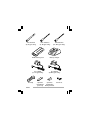
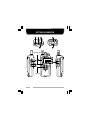
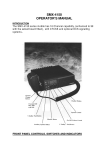
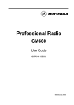
SUPPLIED ACCESSORIES
Item
Antenna
• VHF (K, M types only)
• UHF (K, M types only)
• UHF (K2, M2 types only)
Ni-MH battery pack (KNB-29N)
Battery charger (KSC-31)
AC adaptor
• 120 VAC (K, K2 types only)
• 230 VAC (M, M2 types only)
Belt clip (KBH-10)
Speaker/ microphone
jacks cap
Speaker/ microphone locking
bracket
Screw set
Instruction manual
Part number
Qty.
T90-1036-XX
T90-1039-XX
T90-1040-XX
W09-1000-XX
W08-0969-XX
1
1
1
1
W08-0970-XX
W08-0971-XX
J29-0713-XX
1
B09-0680-XX
1
J19-5472-XX
1
N99-2043-XX
B62-1817-XX
1
1
Note: A type code (K, K2, M, or M2) can be found on the label
attached to the package box.
1
VHF Antenna
(K, M types only)
UHF Antenna
(K2, M2 types only)
Ni-MH battery pack
Battery charger
AC adaptor
(K, K2 types only)
AC adaptor
(M, M2 types only)
Belt clip
2
UHF Antenna
(K, M types only)
Speaker/
Speaker/
microphone
microphone
jacks cap locking bracket
Screw set
PREPARATION
CHARGING THE BATTERY PACK
The battery pack is not charged at the factory; charge it
before use.
Initially charging the battery pack after purchase or extended
storage (greater than 2 months) will not bring the battery pack
to its normal operating capacity. After repeating the charge/
discharge cycle two or three times, the operating capacity will
increase to normal.
◆ Do not recharge the battery pack if it is already fully charged.
Doing so may cause the life of the battery pack to shorten or the
battery pack may be damaged.
◆ After charging the battery pack, disconnect it from the charger. If
the charger power is reset (turned ON after it being turned OFF),
recharging will start again and the battery pack will become
overcharged.
Note:
◆ The ambient temperature should be between 41°F and 104°F
(5°C and 40°C) while charging is in progress. Charging outside
this range may not fully charge the battery.
◆ Always switch OFF the transceiver equipped with a battery pack
before charging. Using the transceiver while charging its battery
pack will interfere with correct charging.
◆ The battery pack life is over when its operating time decreases
even though it is fully and correctly charged. Replace the battery
pack.
3
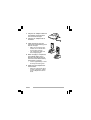
1
2
3
Plug the AC adaptor cable into
the adaptor jack located on
the rear of the charger.
Plug the AC adaptor into an
AC outlet.
Slide the battery pack or a
transceiver with a battery pack
into the charger.
•
Make sure the battery pack
contacts are in contact with
the charging terminals.
The charger LED lights red
and charging begins.
•
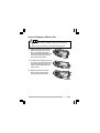
4
When charging is completed,
the indicator lights green.
Remove the battery pack or
the transceiver with a battery
pack from the charger.
•
5
It takes approximately 3 hours
to charge the battery pack.
Unplug the AC adaptor from
the AC outlet.
•
When the charger will not be
used for a long time, unplug
the AC adaptor from the AC
outlet.
4
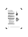
INSTALLING/ REMOVING THE BATTERY PACK
◆ Do not short the battery terminals or dispose of the battery by
fire.
◆ Never attempt to remove the casing from the battery pack.
1
Align the battery pack with the
back of the transceiver, then
press the battery pack and
transceiver firmly together until
the release latch on the base
of the transceiver locks.
2
To remove the battery pack, lift
the safety catch on the base of
the transceiver, then press the
release latch underneath the
safety catch.
3
While pressing the release
latch, pull the battery pack
away from the transceiver.
5
INSTALLING THE ANTENNA
Screw the antenna into the
connector on the top of the
transceiver by holding the antenna
at its base and turning it clockwise
until secure.
Note: The antenna is neither a
handle, a key ring retainer, nor a
speaker/ microphone attachment
point. Using the antenna in these
ways may damage the antenna and
degrade your transceiver’s
performance.
INSTALLING THE BELT CLIP
If desired, attach the belt clip using
the two supplied 3 x 8 mm screws.
Note:
◆ If the belt clip is not installed, its
mounting location may get hot
during continuous transmission
or when left sitting in a hot
environment.
◆ Do not use glue which is designed
to prevent screw loosening when
installing the belt clip, as it may
cause damage to the transceiver.
Acrylic ester, which is contained in
these glues, may crack the
transceiver’s back panel.
6
INSTALLING THE CAP OVER THE SPEAKER/ MICROPHONE JACKS
If you are not using an optional
speaker/ microphone, install the
cap over the speaker/ microphone
jacks using the supplied 3 x 6 mm
screw.
Note: To keep the transceiver water
resistant, you must cover the
speaker/ microphone jacks with the
supplied cap.
INSTALLING THE (OPTIONAL) SPEAKER/ MICROPHONE OR HEADSET
1
Insert the speaker/ microphone
or headset plugs into the
speaker/ microphone jacks.
2
Install the speaker/ microphone
locking bracket over the plugs
using the supplied 3 x 6 mm
screw.
Note: The transceiver is not fully
water resistant when using a
speaker/ microphone or headset.
7
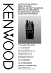
GETTING ACQUAINTED
1
Microphone
Speaker
8
q Antenna connector
Connect an antenna here {page 6}.
w Selector
Your dealer can program the selector as either Zone Up/
Down (default setting) or Channel Up/Down. Rotate the
selector to select a zone or channel.
e Power switch/ Volume control
Turn clockwise to switch ON the transceiver. Rotate to
adjust the volume. Turn counterclockwise fully to switch
OFF the transceiver {page 13}.
r Transmit/ Busy/ Call indicator
This LED lights red while transmitting and green while
receiving a call. The LED flashes orange while receiving
an encoded call (i.e. Code Squelch, etc.) and red when
the battery power is low while transmitting.
t Release Latch
Press the release latch to unlock and remove the battery
pack {page 5}.
y Safety Catch
Lock this catch to avoid accidentally pressing the release
latch and removing the battery pack {page 5}.
u PTT (Push-to-Talk) switch
Press this switch, then speak into the microphone to call a
station.
i Side 1 key
Press to activate its programmable function {page 12}.
The default setting is Squelch Off Momentary.
o Side 2 key
Press to activate its programmable function {page 12}.
The default setting is Lamp.
!0 Display
Refer to the display on pages 10 and 11.
9
!1 S key
Press to activate its programmable function {page 12}.
The default setting is None (no function).
!2 A key
Press to activate its programmable function {page 12}.
The default setting is None (no function).
!3 <B key
Press to activate its programmable function {page 12}.
The default setting is Channel Down.
!4 C> key
Press to activate its programmable function {page 12}.
The default setting is Channel Up.
!5 Speaker/ Microphone jacks
Connect an optional speaker/ microphone or headset here
{page 7}. Otherwise, keep the supplied cap in place.
DISPLAY
Icon
Description
Appears when the key programmed as
Monitor or Squelch Off is pressed.
Appears when you receive a Code Squelch
call or transmit using Code Squelch.
Appears while using the Talk Around
function.
The selected zone is added to the scanning
sequence.
Appears while scanning.
10
Icon
Description
Appears while using the VOX function
Appears when a message is stored in the
transceiver stack memory. Appears and
blinks when a new message has arrived.
The selected channel is set as a Priority
channel.
Appears while using low transmit power on
the selected channel.
The selected channel is added to the
scanning sequence.
Appears when the Scrambler function has
been activated.
Displays the current battery status (full/
sufficent/ low/ requires charging).
Displays the currently selected zone and
channel number or the channel name. Also
displays FleetSync messages.
11
TK-2212/3212 E 01-35
11
04.12.7, 10:03 AM
PROGRAMMABLE FUNCTIONS
Side 1, Side 2, S, A, <B, and C> keys {pages 9 and 10} can
be programmed with the functions listed below. Please
contact your dealer for further details on these functions.
Note: The selector can be programmed as either Zone Up/Down or
Channel Up/Down.
•
•
•
•
•
•
•
•
•
•
•
•
•
•
Autodial
Call 1
Call 2
Channel Down
Channel Up
Direct Zone - Channel
Display Character
Key Lock
Lamp
Low Transmission Power
Monitor
Monitor Momentary
None
Operator Selectable Tone
(OST)
12
•
•
•
•
•
•
•
•
•
•
•
•
•
Scan
Scan Delete/Add
Scrambler
Selcall
Selcall + Status
Squelch Level
Squelch Off
Squelch Off Momentary
Status
Talk Around
VOX
Zone Down
Zone Up
BASIC OPERATIONS
SWITCHING POWER ON/OFF
Turn the Power switch/ Volume control clockwise to switch
the transceiver ON.
•
•
A beep sounds and the display momentarily lights up.
If the Transceiver Password function is programmed,
“PASSWORD” appears on the display. Enter the password to
unlock the transceiver (refer to “Transceiver Password”, below).
Turn the Power switch/ Volume control counterclockwise to
switch the transceiver OFF.
■ Transceiver Password
To enter the Transceiver Password:
1 Rotate the selector to select the first digit of the
password.
2 Press the C> key to accept the entered digit and move
to the next digit.
•
Press the A key to delete an incorrect character. Press
and hold the A key to delete all entered characters.
3
Repeat steps 1 and 2 to enter the entire password.
4
Press the S key to confirm password.
•
•
The password can contain a maximum of 6 digits.
If you enter an incorrect password, an error tone sounds
and the transceiver remains locked.
ADJUSTING THE VOLUME
Rotate the Power switch/ Volume control to adjust the
volume. Clockwise increases the volume and counterclockwise decreases it.
•
You may need to adjust the volume more precisely while
communicating with other parties.
Note: If your dealer programmed Squelch Off or Squelch Off
Momentary onto a PF key, you can use that key to hear background
noise while adjusting the volume level (refer to “Monitor/ Squelch Off”
on page 31).
13
SELECTING A ZONE AND CHANNEL
Select the desired zone using the selector or the keys
programmed as Zone Up/ Zone Down.
•
The default setting for the selector is Zone Up/ Down.
Select the desired channel using the selector or the keys
programmed as Channel Up/ Channel Down.
•
•
The default setting for the <B key is Channel Down.
The default setting for the C> key is Channel Up.
Names can be programmed for channels with up to
8 characters each. The transceiver will display either the
channel name or the zone and channel number. Press the
key programmed as Display Character to toggle between the
two displays.
TRANSMITTING
1
2
Select your desired zone and channel using the selector
and the Zone or Channel keys.
Press the key programmed as Monitor or Squelch Off to
check whether or not the channel is free.
•
3
•
4
If the channel is busy, wait until it becomes free.
Press the PTT switch and speak into the microphone in
your normal speaking voice.
For best sound quality at the receiving station, hold the
microphone approximately 1.5 inches (3 ~ 4 cm) from your
mouth.
Release the PTT switch to receive.
RECEIVING
1
Select your desired zone and channel using the selector
and the Zone or Channel keys.
2
When you hear a caller’s voice, readjust the volume as
necessary.
•
Alternatively, you can turn the Scan function on if desired.
14
SCAN
If the Scan function is programmed, zones or channels can be
scanned by pressing the key programmed as Scan. Scan
can be used as either Single Scan or Multi Scan.
•
•
Single Scan monitors only the channels of the currently selected
zone, which have been added to the scanning sequence. If set
up to scan Priority channels, the Priority channels will be scanned
even if they are not within the currently selected zone.
Multi Scan monitors all channels of every zone, which have been
added to the scanning sequence.
To activate Scan, press the key programmed as Scan.
•
•
•
The
icon and either “SCAN” or the revert zone and channel
number appear on the display.
The zone add indicator (
) will appear on the display
when the selected zone is added to the scan sequence. The
channel add indicator (
) will appear on the display
when the selected channel is added to the scan sequence.
When a call is received, scanning stops and the zone and
channel digits appear. Press the PTT switch and speak into the
microphone to respond to the call. The transceiver will continue
scanning after a predetermined time delay if the PTT switch is
released and no further signal is received.
To stop scanning, press the Scan key again.
Note: You can only use Scan if your dealer has programmed at least
2 channels on the transceiver. Also, there must be at least 2
channels not locked out of Scan.
15
ADD TO SCAN/ DELETE FROM SCAN
Press the key programmed as Scan Delete/Add to add or
remove each channel to or from the scan sequence.
•
The channel add indicator (
) will appear on the
display when the selected channel is added to the scan
sequence.
Press and hold the key programmed as Scan Delete/Add to
add or remove each zone to or from the scan sequence.
•
The zone add indicator (
) will appear on the display
when the selected zone is added to the scan sequence.
PRIORITY SCAN
A Priority channel must be programmed in order for Priority
Scan to function.
The transceiver will automatically change to the Priority
channel when a signal is received on it, even if a signal is
being received on a normal channel.
•
The
icon appears on the display when the Priority channel is
selected.
The transceiver will remain on the Priority channel until the
signal is no longer present.
16
REVERT CHANNEL
During Scan, pressing the PTT switch to transmit will cause
the transceiver to select the revert channel. Your dealer can
program one of the following six types of Revert channels for
your transceiver:
•
•
•
•
•
•
Selected: The zone/ channel selected prior to activating Scan is
assigned as the new revert zone and channel.
Selected + Talkback: The zone/ channel selected prior to
activating Scan is assigned as the new revert zone and channel.
The transceiver also “talks back” on the current receive channel,
allowing you to respond to a call on your current channel before
Scan resumes.
Priority: If your dealer has programmed a Priority channel, this
channel is the revert zone and channel.
Priority + Talkback: If your dealer has programmed a Priority
channel, this channel is the revert zone and channel. The
transceiver also “talks back” on the current receive channel,
allowing you to respond to a call on your current channel before
Scan resumes.
Last Called: The last zone/ channel on which a call was
received is assigned as the new revert zone and channel.
Last Used: The last zone/ channel on which you responded to a
call is assigned as the new revert zone and channel.
17
FleetSync: ALPHANUMERIC 2-WAY PAGING FUNCTION
FleetSync is an Alphanumeric 2-way Paging Function, and is
a protocol owned by KENWOOD Corporation. FleetSync
enables a variety of paging functions on your transceiver,
some of which depend on dealer programming.
SELCALL (SELECTIVE CALLING)
A Selcall is a voice call to a particular station or to a group of
stations.
■ Transmitting
1
2
Select your desired zone and channel.
Press the key programmed as Selcall or
Selcall + Status to enter Selcall mode.
3
Press the <B and C> keys to select the ID of the
station you want to call.
Press the PTT switch and begin your conversation.
•
4
•
The last selected station ID appears on the display.
Alternatively, you can press the Side 2 key to page the
selected station, rather than making a voice call.
■ Receiving
An alert tone will sound, the transceiver will automatically
enter Selcall Mode, and the calling station’s ID will appear
when a Selcall is received.
To respond to the call, press the PTT switch and speak
into the microphone.
18
■ Identification Codes
An ID code is a combination of a 3-digit Fleet number and
a 4-digit ID number. Each transceiver must have its own
Fleet and ID number.
•
•
•
•
•
Enter a Fleet number (100 ~ 349) to make a group call.
Enter an ID number (1000 ~ 4999) to make an individual call
in your fleet.
Enter a Fleet number to make a call to all units in the selected
fleet (Interfleet call).
Enter an ID number to make a call to the selected ID in all
fleets (Supervisor call).
Select “ALL” Fleet and “ALL” ID to make a call to all units
(Broadcast call).
Note: The ID range may be limited by programming.
STATUS MESSAGE
You can send and receive 2-digit Status messages which may
be decided in your talk group. Messages can contain up to 16
alphanumeric characters. Status messages range from 10 to
99 (80 ~ 99 are reserved for special messages).
A maximum of 5 received messages can be stored in the
Stack memory of your transceiver. These saved messages
can be reviewed after reception. Depending on your dealer
settings, when the Stack memory is full, either the oldest
message will be erased when a new message is received or
the new message will not be stored in the stack memory. The
icon lights when a message is stored in the Stack memory.
19
■ Transmitting
1
2
Select your desired zone and channel.
Press the key programmed as Status to enter Status
mode or Selcall + Status to enter Selcall mode.
•
3
4
5
6
When using the Status key to enter Status mode, the
target Fleet/ ID is fixed and cannot be selected. Skip to
step 5 to continue.
In Selcall mode, press the <B and C> keys to select
the ID of the station you want to call.
Press the S key again to enter Status Mode.
Press the <B and C> keys to select the status ID you
want to transmit.
Press the PTT switch or Side 2 key to initiate the
Status call.
•
“COMPLETE” is displayed when the call has been
successfully transmitted.
■ Receiving
The
icon will flash and a calling ID or text message will
appear when a Status call is received.
Press any key to return to normal operation.
20
■ Reviewing Messages in the Stack Memory
1
Press and hold the key programmed as Selcall,
Status, or Selcall + Status for 1 second to enter the
Stack memory.
•
2
Press the <B and C> keys to select the desired
message.
•
3
The last received message is displayed with the message
number.
Press and hold the S key to toggle between the call ID/
message and the channel name.
Press the Side 1 key to return to normal operation.
•
•
To delete the selected message, press the A key. To
confirm the deletion, press the S key.
To delete all messages, press and hold the A key for
1 second. To confirm the deletion, press the S key.
21
DTMF SIGNALING
CODE SQUELCH
Code Squelch is enabled or disabled by your dealer. This
function turns the transceiver squelch OFF only when it
receives the DTMF code that has been set up in your
transceiver. Transceivers that do not transmit the correct
code will not be heard. Consequently, you can communicate
with a specific party without listening to other parties using the
same channel.
Your dealer may also activate Group Call for your transceiver.
This is useful when you want to send information to a number
of units in a fleet. Ask your dealer for details.
Note: Code Squelch cannot be used on this transceiver if Selective
Call {page 24} or DTMF Number Display {page 26} have been
programmed.
■ Transmitting
1
2
Select your desired zone and channel.
Press and hold the PTT switch.
•
3
The icon appears on the display and the LED indicator
lights red.
Use the transceiver the same as in a regular call; press
the PTT switch to transmit and release it to receive.
•
•
•
22
The called transceiver’s squelch will turn OFF while you
are transmitting. After you stop transmitting, the squelch
will turn back ON after a pre-set time period elapses.
This time period is programmed by your dealer.
When you release the PTT switch, squelch turns OFF and
the LED indicator flashes orange. When you receive a
signal, the LED indicator flashes green and orange.
When the signal drops out, the LED indicator flashes
orange again. If no signal is received for a
pre-determined time, squelch turns back ON.
Pressing the key programmed as Monitor at any time will
turn the squelch back ON.
■ Autodial
1
Press the key programmed as Autodial.
2
Press the <B and C> keys to select your desired
Autodial list number.
Press the PTT switch or Side 2 key to make the call.
•
3
The first entry in the Autodial list appears on the display.
■ Receiving
When you receive a signal containing the correct code,
squelch turns OFF and you will hear the call.
•
•
•
•
•
The icon appears on the display and flashes and the LED
indicator flashes orange.
To mute the speaker after squelch turns OFF, press the key
programmed as Monitor.
Your dealer can program squelch to automatically turn back
ON after a specific time period elapses.
If Transpond for Code Squelch is programmed, an
acknowledgment signal is returned to the calling station.
Transpond does not function when you are called with a
Group code. Transpond for Code Squelch can send an alert
tone, a transceiver ID code, or the code stored in Autodial
Memory location 1 (if programmed).
If Call Alert for Code Squelch is programmed, an alert tone
will sound when the correct code is received.
23
SELECTIVE CALL
Selective Call is enabled or disabled by your dealer. This
function is similar to Code Squelch {page 20}. The
differences from Code Squelch are as follows:
•
•
You can transmit or receive message codes containing a
maximum of 5 digits.
Selective Call turns the squelch OFF only when the transceiver
receives a predetermined DTMF code in the correct sequence: a
3-digit ID code, a 1-digit Intermediate code, and a message code
(up to 5 digits).
Your dealer may also activate Group Call for your transceiver.
This is useful when you want to send information to a number
of units in a fleet. Ask your dealer for details.
Note: Selective Call cannot be used on this transceiver if Code
Squelch {page 22} and DTMF Number Display {page 26} have been
programmed.
■ Transmitting
1
2
Select your desired zone and channel.
Press and hold the PTT switch.
•
3
The icon appears on the display and the LED indicator
lights red.
Use the transceiver the same as in a regular call; press
the PTT switch to transmit and release it to receive.
•
•
•
24
The called transceiver’s squelch will turn OFF while you
are transmitting. After you stop transmitting, the squelch
will turn back ON after a pre-set time period elapses.
This time period is programmed by your dealer.
When you release the PTT switch, squelch turns OFF and
the LED indicator flashes orange. When you receive a
signal, the LED indicator flashes green and orange.
When the signal drops out, the LED indicator flashes
orange again. If no signal is received for a
pre-determined time, squelch turns back ON.
Pressing the key programmed as Monitor at any time will
turn the squelch back ON.
■ Autodial
1
Press the key programmed as Autodial.
2
Press the <B and C> keys to select your desired
Autodial list number.
Press the PTT switch or Side 2 key to make the call.
•
3
The first entry in the Autodial list appears on the display.
■ Receiving
When you receive the correct ID and Intermediate codes,
squelch turns OFF and you will hear the call. If a
message code is also received, the message code
appears on the display.
•
•
•
•
•
•
•
•
The icon appears on the display and flashes and the LED
indicator flashes orange.
When you receive a call with your ID code, “C” appears on
the display (i.e.- C 12345).
When you receive a call with you Group code, “A” appears on
the display (i.e.- A 12345).
When no message is received, “NO DATA” appears on the
display.
To mute the speaker after squelch turns OFF, press the key
programmed as Monitor.
Your dealer can program squelch to automatically turn back
ON after a specific time period elapses.
If Transpond for Selective Call is programmed, an acknowledgment
signal is returned to the calling station. Transpond does not
function when you are called with a Group code. Transpond for
Selective Call can send an alert tone, a transceiver ID code, or the
code stored in Autodial Memory location 1 (if programmed).
If Call Alert for Selective Call is programmed, an alert tone
will sound when the correct codes are received.
25
STUN
This function is used when a transceiver is stolen or lost.
When the transceiver receives a call containing a stun code,
either transmit mode will be disabled, or both receive mode
and transmit mode will be disabled. The stun code is
cancelled when the transceiver receives a call with a revive
code.
DTMF NUMBER DISPLAY
Note: This features can only be activated when DTMF Signaling is
turned OFF.
When you receive a DTMF code containing at least 3 digits, it
will appear on the display. Each successive digit will continue
to scroll across the display, as long as each digit is received
within 1 second of the previous digit. If no digit is received for
more than 1 second, then when a new digit is received, the
display will clear and begin with the new digit.
Cancel the DTMF Number Display by pressing any key.
26
QUIET TALK (QT)/ DIGITAL QUIET TALK (DQT)
Your dealer may have programmed QT or DQT signaling on
your transceiver channels. A QT tone/ DQT code is a
sub-audible tone/code which allows you to ignore (not hear)
calls from other parties who are using the same channel.
When a channel is set up with a QT tone or DQT code,
squelch will only open when a call containing a matching tone
or code is received. Likewise, signals that you transmit will
only be heard by parties whose QT/ DQT signaling matches
your transceiver.
If a call containing a different tone or code is made on the
same channel you are using, squelch will not open and you
will not hear the call. This allows you to ignore (not hear)
these calls. Although it may seem like you have your own
private channel while using QT/ DQT, other parties can still
hear your calls if they set up their transceiver with the same
tone or code.
OPERATOR SELECTABLE TONE (OST)
If a key has been programmed with OST, you can reprogram
the QT tone or DQT code on each channel.
1 Select your desired channel.
2 Press the key programmed as OST.
•
3
4
The current OST tone pair or “Tone OFF” appears on the
display.
Press the <B or C> keys to select your desired tone pair
from 1 to 40, then operate the transceiver as normal.
Press the Side 1 or S key to exit Operator Selectable Tone
and return to normal operation.
27
VOICE OPERATED TRANSMISSION (VOX)
VOX can be activated or deactivated by your dealer. VOX
operation allows you to transmit hands-free. This feature can
only be used if you are using a supported headset.
When operating VOX, you must set a VOX Gain level. This
setting allows the transceiver to recognize sound levels. If the
microphone is too sensitive, it will begin transmitting when
there is noise in the background. If it is not sensitive enough,
it will not pick up your voice when you begin speaking. Be
sure to adjust the VOX Gain level to an appropriate sensitivity
to allow smooth transmission.
VOX GAIN LEVEL
1
Connect the headset to the transceiver.
•
2
Press the key programmed as VOX.
•
3
The VOX Gain can be adjusted from levels 1 (low sensitivity)
to 10 (high sensitivity). The default setting is level 5.
While adjusting the Gain level, speak into the headset
microphone as you would while under normal operation, to
test the sensitivity level.
•
•
5
The current VOX Gain level appears on the display.
Press the <B and C> keys to decrease or increase the
VOX Gain level.
•
4
The VOX function does not activate when a headset is not
connected to the accessory terminal of the transceiver.
When the microphone recognizes a sound, the LED lights
orange. This allows you to determine a suitable level where
background noise will not activate VOX operation while
speaking into the microphone will activate it.
The transceiver does not transmit your voice during this test
procedure.
Press the Side 1 or S key to save the setting.
28
VOX OPERATION
1
Connect the headset to the transceiver.
•
The VOX function does not activate when a headset is not
connected to the accessory terminal of the transceiver.
2
Press and hold the key programmed as VOX for
2 seconds.
3
To transmit, simply speak into the microphone.
•
•
4
) appears on the display.
The transceiver recognizes sound levels depending on the
VOX Gain level. If the microphone is too sensitive, it will
begin transmitting when there is noise in the background. If it
is not sensitive enough, it will not pick up your voice when
you begin speaking. Be sure to adjust the VOX Gain level to
an appropriate sensitivity to allow smooth transmission.
When you finish speaking, the transceiver automatically
returns to receive mode.
•
5
The VOX icon (
Depending on the pre-programmed delay time, it may take a
moment before returning to receive mode. The delay time
ensures that the end of your conversation is not cut off when
you finish speaking.
To turn the VOX function OFF, press and hold the VOX
key again, for 2 seconds.
Note:
◆ If a speaker/ microphone is connected to the transceiver while
the VOX function is switched ON and the VOX Gain Level is
configured to a higher, more sensitive level, louder received
signals may cause the transceiver to start transmission.
◆ When you operate the VOX function, you must use an optional
KHS-1, KHS-21, or KHS-22 accessory.
29
ADVANCED OPERATIONS
SELECTING A TRANSMIT POWER
Each channel is programmed with either high or low transmit
power by your dealer. You can change the transmit power of
only channels programmed as high.
When you can reliably communicate with other parties without
using high transmit power, select low transmit power by pressing
the key programmed as Low Transmission Power. Each time
you press Low Transmission Power, the transmit power
toggles between high and low.
•
•
The icon appears while using low transmit power.
Using low transmit power conserves battery power and reduces
the risk of interfering with other communications.
Note:
◆ Pressing Low Transmission Power while using a channel
programmed with low transmit power causes an error tone to
sound.
◆ When changing a channel from high transmit power to low
transmit power, all channels programmed with high transmit
power are changed to low transmit power.
KEY LOCK
This function is used to help prevent any accidental operation
of the transceiver.
To lock the transceiver keys, press and hold the key
programmed as Key Lock for 1 second.
•
•
"LOCKED" appears on the display.
You can continue to use the following functions (if available):
Key Lock, Lamp, Monitor, Monitor Momentary, PTT, Squelch
Off, and Squelch Off Momentary.
To unlock the keys, press and hold the Key Lock key again
for 1 second.
30
MONITOR/ SQUELCH OFF
You can use the key programmed as Monitor/ Squelch Off to
listen to weak signals that you cannot hear during normal
operation and to adjust the volume when no signals are
present on your selected channel.
•
The icon appears on the display while Monitor/ Squelch Off is
active.
Your dealer can program a key with one of 4 functions:
• Monitor: Momentarily press to deactivate QT, DQT, or
optional signaling. Press the key again to return to normal
operation.
• Monitor Momentary: Press and hold to deactivate QT,
DQT, or optional signaling. Release the key to return to
normal operation.
• Squelch Off: Momentarily press to hear background
noise. Press the key again to return to normal operation.
• Squelch Off Momentary: Press and hold to hear
background noise. Release the key to return to normal
operation.
■ Squelch Level
To adjust the squelch level:
1 Press the key programmed as Squelch Level.
2 Press the <B key to decrease the squelch level (open)
and the C> key to increase the squelch level (tighten).
3 Press the Side 1 or S key to store the new setting and
exit the squelch level adjustment.
31
SCRAMBLER
Although the scrambler function does not offer complete
privacy with your calls, it does prevent others from easily
listening in on your calls. When activated, the transceiver
distorts your voice so that anybody listening to your call will
be unable to clearly hear what you are saying.
In order for members of your own group to clearly hear your
call while you are using the scrambler, all other members
must also activate the scrambler functions on their
transceivers. This distorts everybody’s voice while
transmitting and corrects the voice message on your own
transceiver when you receive the call.
To activate the scrambler, press the key programmed as
Scrambler.
•
The
icon appears on the display while the scrambler is active.
To deactivate the scrambler, press the Scrambler key again.
TALK AROUND
You may occasionally experience an interruption in service
(due to a power failure, etc.). During such an occurence, you
can continue communication by using the Talk Around feature,
if it has been programmed by your dealer. Talk Around allows
you to communicate directly with other transceivers, without
the use of a repeater. However, if the station you want to
contact is too far away, or there are geographical obstacles in
the way, you may not be able to contact the station.
Toggle Talk Around on and off by pressing the key
programmed as Talk Around.
•
•
The appears on the display while Talk Around is active.
When using Talk Around, the receive frequency is used for both
transmitting and receiving, and the decode signaling is used for
both encoding and decoding.
32
TRANSCEIVER BACKLIGHT
To turn the transceiver display and keypad backlight on, press
the key programmed as Lamp.
•
Pressing any key other than the PTT switch and the Power
switch/ Volume control while the backlight is on will reset the
backlight timer, allowing it to remain lit for an additional 5
seconds.
To turn the transceiver backlight off immediately, press the
Lamp key while the backlight is on.
33
BACKGROUND OPERATIONS
TIME-OUT TIMER (TOT)
The purpose of the Time-out Timer is to prevent any caller
from using a channel for an extended period of time.
Your dealer can program the TOT in the range of 15 seconds
to 10 minutes. If you continuously transmit for a period of
time that exceeds this programmed time, the transceiver will
stop transmitting and an alert tone will sound. To stop the
tone, release the PTT switch.
Your dealer can also program a warning function to alert you
before the TOT expires. Continuously transmitting for the
time specified by your dealer will cause the warning tone to
sound.
BATTERY SAVER
When activated by your dealer, the Battery Saver function
decreases the amount of power used when a signal is not
being received and no operations are being performed (no
keys are being pressed and no switches are being turned).
While the channel is not busy and no operation is performed
for 5 seconds, Battery Saver activates. When a signal is
received or an operation is performed, Battery Saver is
disabled.
COMPANDER
This background feature allows higher clarity of signals,
avoiding excessive noise and interference. If the
transceiver’s internal compander has been programmed by
your dealer, transmitted signals are compressed before being
sent and received signals are expanded when they arrive.
34
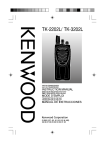
BATTERY POWER INDICATOR
The battery power indicator displays the battery power
remaining, as illustrated below:
High
Sufficient
Low
Very low (flashing)
When the battery power is very low, replace or recharge the
battery pack. If activated by your dealer, an alert tone will
sound every 30 seconds and the LED indicator will blink red
when the battery power is low while transmitting.
BUSY CHANNEL LOCKOUT (BCL)
When activated, BCL prevents you from interfering with other
parties who may be using the same channel that you
selected. Pressing the PTT switch while the channel is in use
will cause your transceiver to emit an alert tone and
transmission will be inhibited (you cannot transmit). Release
the PTT switch to stop the tone and return to receive mode.
Note: Ask your dealer for an explanation on how BCL functions
when using QT, DQT, DTMF, or FleetSync signaling.
BEGINNING/ END OF TRANSMIT SIGNAL
The Beginning of Transmit and End of Transmit identification
signals are used to access and release some repeaters.
If Beginning of Transmit is set, the ID signal is transmitted
when you press the PTT switch.
If End of Transmit is set, the ID signal is transmitted when you
release the PTT switch.
If both are set, the ID signal is transmitted when you press
and release the PTT switch.
35