1
INSTRUCTION MANUAL
VHF FM TRANSCEIVER
TK-780 series
TK-880 series
TK-980
TK-981
UHF FM TRANSCEIVER
800 MHz FM TRANSCEIVER
900 MHz FM TRANSCEIVER
KENWOOD CORPORATION
© B62-1549-00 (K)
09 08 07 06 05 04 03 02 01 00
THANK YOU!
We are grateful you chose KENWOOD for your personal mobile applications. We
believe this easy-to-use transceiver will provide dependable communications to keep
personnel operating at peak efficiency.
KENWOOD transceivers incorporate the latest in advanced technology. As a result,
we feel strongly that you will be pleased with the quality and features of this product.
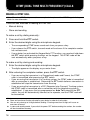
MODELS COVERED BY THIS MANUAL
The models listed below are covered by this manual:
• TK-780:
VHF FM Transceiver
• TK-780H: VHF FM Transceiver
• TK-880:
UHF FM Transceiver
• TK-880H: UHF FM Transceiver
• TK-980:
800 MHz FM Transceiver
• TK-981:
900 MHz FM Transceiver
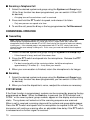
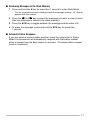
PRECAUTIONS
Please observe the following precautions to prevent fire, personal injury, and
transceiver damage.
•
Do not attempt to configure the transceiver while driving; it is too dangerous.
•
Do not modify the transceiver for any reason.
•
Do not expose the transceiver to long periods of direct sunlight, nor place it near
heating appliances.
•
Do not place the transceiver in excessively dusty, humid, or wet areas, nor on
unstable surfaces.
•
If an abnormal odor or smoke is detected coming from the transceiver, turn OFF
the power immediately. Contact your KENWOOD dealer.
CONTENTS
UNPACKING AND CHECKING EQUIPMENT ................................... 1
SUPPLIED ACCESSORIES .......................................................... 1
PREPARATION .................................................................................. 2
TOOLS REQUIRED ...................................................................... 2
POWER CABLE CONNECTION .................................................. 2
INSTALLING THE TRANSCEIVER .............................................. 3
ORIENTATION .................................................................................... 4
FRONT PANEL AND MICROPHONE ........................................... 4
DISPLAY ........................................................................................ 5
REAR PANEL ................................................................................ 5
PROGRAMMABLE AUXILIARY FUNCTIONS .................................. 6
BASIC OPERATIONS ........................................................................ 8
OPERATION OVERVIEW ............................................................. 8
Trunking Format ..................................................................... 8
Conventional Format
(TK-780 series and TK-880 series only) ............................... 8
SWITCHING POWER ON/OFF ..................................................... 8
ADJUSTING THE VOLUME ......................................................... 8
SELECTING A SYSTEM/ GROUP/ CHANNEL ............................ 8
TIME-OUT TIMER (TOT) ............................................................... 8
HORN ALERT ............................................................................... 8
TRUNKING FORMAT ......................................................................... 9
TRUNKED OPERATION ............................................................... 9
Placing a Dispatch Call .......................................................... 9
Receiving a Dispatch Call ...................................................... 9
Placing a Telephone Call ....................................................... 9
Receiving a Telephone Call ................................................. 10
CONVENTIONAL OPERATION .................................................. 10
Transmitting .......................................................................... 10
Receiving ............................................................................... 10
SYSTEM SCAN ........................................................................... 10
Scanning Trunked Systems .................................................. 11
Scanning Conventional Systems ......................................... 11
Scan Lockout ......................................................................... 11
Scan Revert ............................................................................ 11
GROUP SCAN .............................................................................. 11
i
CONVENTIONAL FORMAT
(TK-780 series and TK-880 series only) .......................................
CONVENTIONAL OPERATION ..................................................
Transmitting ..........................................................................
Receiving ...............................................................................
SCAN ...........................................................................................
Priority Scan ..........................................................................
2-TONE SIGNALLING ................................................................
FleetSync™: ALPHANUMERIC TWO-WAY PAGING FUNCTION ...
KEY FUNCTIONS .......................................................................
OPTIONAL FEATURES ..............................................................
SELCALL (SELECTIVE CALLING) ............................................
Transmitting ..........................................................................
Receiving ...............................................................................
Identification Codes .............................................................
Reviewing Caller IDs in the Stack Memory ........................
STATUS MESSAGE ....................................................................
Transmitting ..........................................................................
Receiving ...............................................................................
Reviewing Messages in the Stack Memory .......................
Automatic Status Response ................................................
DTMF (DUAL TONE MULTI FREQUENCY) CALLS ........................
MAKING A DTMF CALL .............................................................
DTMF SIGNALLING ....................................................................
DBD (DEAD BEAT DISABLE) ....................................................
AUDIBLE USER FEEDBACK TONES .............................................
NOTICES TO THE USER ..................................................................
ii
12
12
12
12
13
13
13
14
14
14
15
15
15
15
15
16
16
16
17
17
18
18
19
19
20
21
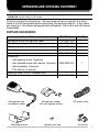
UNPACKING AND CHECKING EQUIPMENT
Note: The following unpacking instructions are for use by your KENWOOD dealer, an authorized
KENWOOD service facility, or the factory.
Carefully unpack the transceiver. We recommend that you identify the items
listed in the following table before discarding the packing material. If any items
are missing or have been damaged during shipment, file a claim with the carrier
immediately.
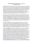
SUPPLIED ACCESSORIES
Item
Part Number
Quantity
Microphone and microphone cable
Microphone hanger with self-tapping screws
DC power cable
Mounting bracket
Speaker jack cap
Screw set:
• Self-tapping screw (4 pieces)
• Hex-headed screw with washer (4 pieces)
• Spring washer (4 pieces)
• Flat washer (4 pieces)
Warranty card (U.S.A./ Canada only)
Instruction manual
T91-0621-XX
J19-1584-XX
E30-3339-XX
J29-0627-XX
B09-0235-XX
1
1 set
1
1
1
N99-0395-XX
1
––
B62-1549-XX
1
1
Microphone and
microphone cable
Mounting bracket
Microphone hanger
with self-tapping screws
Speaker jack cap
DC power cable
Screw set
1
PREPARATION
Various electronic equipment in your vehicle may malfunction if they are not properly protected from
the radio frequency energy which is present while transmitting. Electronic fuel injection, anti-skid
braking, and cruise control systems are typical examples of equipment that may malfunction. If your
vehicle contains such equipment, consult the dealer for the make of vehicle and enlist his/her aid in
determining if the equipment will perform normally while transmitting.
Note: The following preparation instructions are for use by your KENWOOD dealer, an authorized
KENWOOD service facility, or the factory.
TOOLS REQUIRED
Note: Before installing the transceiver, always check how far the mounting screws will extend below
the mounting surface. When drilling mounting holes, be careful not to damage vehicle wiring or parts.
The following tools are required for installing the transceiver:
• 6 mm (1/4 inch) or larger electric drill
• Drill bits (sizes listed below) and circle cutters
Drill Bit Size
Purpose
4.2 mm (5/32 inch)
3.2 mm (1/8 inch)
5 x 16 mm self-tapping screws
4 x 16 mm self-tapping screws
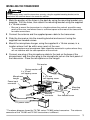
POWER CABLE CONNECTION
The transceiver operates in 12 V negative ground systems only! Check the battery polarity and
voltage of the vehicle before installing the transceiver.
1 Check for an existing hole, conveniently located in the firewall, where the
power cable can be passed through.
• If no hole exists, use a circle cutter to drill the firewall, then install a rubber
grommet.
2 Run the two power cable leads through the firewall and into the engine
compartment, from the passenger compartment.
3 Connect the red lead to the positive (+) battery terminal and the black lead to
the negative (–) battery terminal.
• Locate the fuse as close to the battery as possible.
4 Coil and secure the surplus cable with the provided retaining band.
• Be sure to leave enough slack in the cables so the transceiver can be removed for
servicing while keeping the power applied.
2
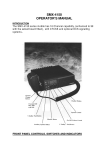
INSTALLING THE TRANSCEIVER
For passenger safety, install the transceiver securely, using the supplied mounting bracket, so the
transceiver will not break loose in the event of a collision.
1 Mark the position of the holes in the dash by using the mounting bracket as a
template. Drill the holes, then attach the mounting bracket using the supplied
5 x 16 mm screws.
• Be sure to mount the transceiver in a location where the controls are within easy
reach of the user, and where there is sufficient space at the rear of the transceiver
for cable connections.
2 Connect the antenna and the supplied power cable to the transceiver.
3 Slide the transceiver into the mounting bracket and secure it using the
supplied hex-headed screws.
4 Mount the microphone hanger, using the supplied 4 x 16 mm screws, in a
location where it will be within easy reach of the user.
• The microphone and microphone cable should be mounted in a place where they
will not interfere with the safe operation of the vehicle.
5 Connect one plug of the microphone cable to the jack on the base of the
micropohone, and the other plug to the microphone jack on the front panel of
the transceiver. Place the microphone on the hanger.
Flat washer
Spring washer
4 x 16 mm
self-tapping screw
Microphone
hanger
5 x 16 mm
self-tapping screw
Power input
connector
Mounting
bracket
Antenna
connector
Hex-headed screw
DC power cable
* The above diagram shows the TK-780 series/ TK-880 series transceiver. The antenna
connector of the TK-980 and TK-981 transceivers is different.
3
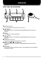
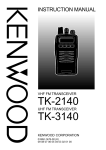
ORIENTATION
FRONT PANEL AND MICROPHONE
q
t
w
e
r
y
u
q IO (Power) switch
Press to switch the transceiver ON (or OFF).
w
/
keys
Press these keys to activate their programmable auxiliary functions
{page 6}.
e Display
See page 5 for more information.
r
/
keys
Press these keys to activate their programmable auxiliary functions
{page 6}.
t Microphone connector
Insert the microphone plug into this connector.
y MON, A, B, tC, Ds
s, and SCN keys
Press these keys to activate their programmable auxiliary functions
{page 6}.
u PTT switch
To transmit, press and hold this switch, then speak into the microphone.
Release to receive.
4
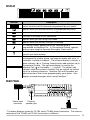
DISPLAY
Indicator
Description
Displays the system, group, and channel numbers. Also displays
various functions which have been programmed by your dealer.
Appears when the selected channel is programmed as priority.
Appears when the key programmed as Monitor is pressed.
This icon is not used on this transceiver.
Appears when you are using Scan mode.
Appears when the auxiliary function is activated.
In Trunking Format, appears when the selected group is
programmed as telephone IDs. In Conventional Format, appears
when you are using the Operator Selectable Tone function.
Flashes when you receive a message. Lights when a message is
stored in the stack memory.
Displays the system, group, and channel numbers. Your dealer
can program the system, group, and channel names with up to 10
characters, in place of numbers. The left most display is used as a
delete indicator ( ) in Trunking Format and an add indicator ( ) in
Conventional Format. The right most display is used for the
Selective Call ( ) or Scrambler ( _ ) function. The delete/ add
indicators show the systems/ channels that are locked/ not locked
out of the scanning sequence. Selective Call and Scrambler are
optional functions that can be programmed by your dealer. Also
displays received messages when using FleetSync .
REAR PANEL
Power input
connector
External
speaker jack
Antenna connector
* The above diagram shows the TK-780 series/ TK-880 series transceiver. The antenna
connector of the TK-980 and TK-981 transceivers is different.
5
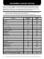
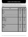
PROGRAMMABLE AUXILIARY FUNCTIONS
Keys w, r, and y {page 4} can be programmed with the auxiliary functions
listed in the following table. The keys can only be programmed with functions,
depending on whether you are using Conventional Format or Trunking Format.
Please contact your dealer for further details on these functions.
Note:
◆ If “Function” is programmed onto one of the above mentioned keys, the DTMF keypad (keypad
models only) can also be used for additional programmable keys.
◆ Only the TK-780 series and TK-880 series transceivers support Conventional Format.
Function
Auto Tel
AUX A
AUX B 1
Channel Down
Channel Up
DTMF ID (BOT)
DTMF ID (EOT)
Display Character
Emergency 2
Function
Group Down
Group Up
Home Channel
Home Group
Horn Alert
Key Lock
Memory (RCL/STO)
Memory (RCL)
Memory (STO)
Message Mode
Monitor A (Monitor Unmute (Momentary))
Monitor B (Monitor Unmute (Toggle))
Monitor C (Carrier Squelch (Momentary))
Monitor D (Carrier Squelch (Toggle))
6
Conventional
Format
No
Yes
Yes
Yes
Yes
Yes
Yes
Yes
Yes
Yes
Yes
Yes
Yes
No
Yes
Yes
Yes
Yes
Yes
Yes
Yes
Yes
Yes
Yes
Trunking
Format
Yes
Yes
Yes
No
No
Yes
Yes
Yes
Yes
Yes
Yes
Yes
No
Yes
Yes
Yes
Yes
Yes
Yes
Yes
Yes
Yes
Yes
Yes
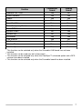
Function
Operator Sel Tone
Public Address
Redial
Scan
Scan Del/Add
Scan Temporary Delete
Send GPS 3
System Down
System Up
Scrambler 4
Talk Around
Tel Disconnect
Volume Down
Volume Up
1
2
3
4
Conventional
Format
Yes
Yes
Yes
Yes
Yes
No
Yes
No
No
Yes
Yes
No
Yes
Yes
Trunking
Format
No
Yes
Yes
Yes
Yes
Yes
Yes
Yes
Yes
Yes
No
Yes
Yes
Yes
This function can be selected only when the Scrambler/ ANI board has not been
installed.
This function can be used only with a foot switch.
This function can be selected only when the FleetSync™ enhanced option and a GPS
receiver have been installed.
This function can be selected only when the Scrambler board has been installed.
7
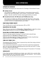
BASIC OPERATIONS
OPERATION OVERVIEW
Your dealer can program your transceiver for Trunking or Conventional Format.
■ Trunking Format
This format can handle up to 600 channels in conventional mode, and 32
systems with up to 250 groups in each system in trunking mode. Systems,
groups, channels, and their functions are programmed by your dealer.
■ Conventional Format (TK-780 series and TK-880 series only)
This format can handle up to 250 groups with 250 channels in each group.
The transceiver can be used only in conventional mode. Groups, channels,
and their functions are programmed by your dealer.
SWITCHING POWER ON/OFF
Press the IO switch to switch the transceiver ON (or OFF).
ADJUSTING THE VOLUME
Press the key programmed as Volume Up or Volume Down to adjust the volume.
Volume Up increases the volume and Volume Down decreases it.
SELECTING A SYSTEM/ GROUP/ CHANNEL
Select the desired system and group (Trunking Format) using the keys
programmed with the System and Group functions.
Select the desired group and channel (Conventional Format) using the keys
programmed with the Group and Channel functions.
TIME-OUT TIMER (TOT)
The purpose of the Time-out Timer is to prevent any caller from using a channel
for an extended period of time.
If you continuously transmit for a period of time that exceeds the programmed
time, the transceiver will stop transmitting and an alert tone will sound. To stop
the tone, release the PTT switch.
Your dealer can program the TOT time in the range of 15 seconds to 10 minutes.
HORN ALERT
If Horn Alert has been installed by your dealer, your vehicle horn, or some other
type of external alert, will sound when certain calls are received. This is a useful
function when you are away from your vehicle.
8
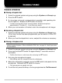
TRUNKING FORMAT
TRUNKED OPERATION
■ Placing a Dispatch Call
1 Select the desired system and group using the System and Group keys.
2 Press the PTT switch.
3 If a tone does not sound, communication is possible; start speaking into
the microphone. Release the PTT switch to receive.
• For best sound quality at the receiving station, hold the microphone
approximately 1.5 inches (3 ~ 4 cm) from your mouth.
4 When your conversation is finished, return the microphone to its hanger.
■ Receiving a Dispatch Call
1 Select the desired system and group using the System and Group keys.
(If the Scan function has been programmed, you can switch it ON or OFF
as desired.)
2 When you hear the dispatcher’s voice, readjust the volume as necessary.
■ Placing a Telephone Call
Note: You can only make a telephone call if the telephone service is available and you have an
optional keypad microphone. Refer to “MAKING A DTMF CALL” on page 18. Consult your dealer
for further details.
1 Select the desired system and group using the System and Group keys.
2 Press and hold the PTT switch for approximately 1 second to ensure a
connection.
• Confirm that there is a dial tone after releasing the PTT switch.
3 Dial using the microphone keypad.
• After dialing, wait for a response from the called party.
4 When the called party responds, press the PTT switch and speak into the
microphone. Release the PTT switch to receive.
• Only one person can speak at a time.
5 To end the call, press the # key or the key programmed as Tel Disconnect.
9
■ Receiving a Telephone Call
1 Select the desired system and group using the System and Group keys.
(If the Scan function has been programmed, you can switch it ON or OFF
as desired.)
• A ringing tone will sound when a call is received.
2 Press and hold the PTT switch to speak, and release it to listen.
• Only one person can speak at a time.
3 To end the call, press the # key or the key programmed as Tel Disconnect.
CONVENTIONAL OPERATION
■ Transmitting
Note: Before transmitting, monitor the channel to make sure it is not already in use. If the
selected group is programmed with QT (Quiet Talk) or DQT (Digital Quiet Talk), remove the
microphone from the hook to disable QT or DQT, then listen to the channel to make sure nobody
is talking on it. If the selected group is not programmed with QT or DQT, simply listen to the
channel to make sure nobody is talking on it. In this case, you need not remove the microphone
from the hook.
1 Select the desired system and group using the System and Group keys.
• If the channel is busy, wait until it becomes free.
2 Press the PTT switch and speak into the microphone. Release the PTT
switch to receive.
• For best sound quality at the receiving station, hold the microphone
approximately 1.5 inches (3 ~ 4 cm) from your mouth.
3 When your conversation is finished, return the microphone to its hanger.
■ Receiving
1 Select the desired system and group using the System and Group keys.
(If the Scan function has been programmed, you can switch it ON or OFF
as desired.)
2 When you hear the dispatcher’s voice, readjust the volume as necessary.
SYSTEM SCAN
If the Scan function is programmed, systems can be scanned by pressing the key
programmed as Scan. When the Scan key is pressed, the SCN indicator and “SCAN-” or the revert system/ group number, appear on the display and scanning
starts. The systems not locked out of the scanning sequence are scanned.
When a call is received, scanning stops and the system and group digits appear.
Press the PTT switch and speak into the microphone to respond to the call. The
transceiver will continue scanning after an adjustable time delay if the PTT switch
is released and no further signal is received.
10
■ Scanning Trunked Systems
When scanning trunked systems, the revert groups and the groups not locked
out of the scanning sequence are scanned. See “GROUP SCAN”, below.
■ Scanning Conventional Systems
When scanning conventional systems, the revert groups and the groups not
locked out of the scanning sequence are scanned. See “GROUP SCAN”,
below.
■ Scan Lockout
If a programmable auxiliary key is programmed with Scan DEL/ADD, each
system can be locked out of the scan sequence manually. The delete
indicator ( ) will appear in the display when the selected system is locked
out.
■ Scan Revert
You can select revert systems and groups using the System and Group keys.
Four types of Scan Reverts which can be programmed by your dealer are
available:
•
Last Called Revert: The last system/ group received is assigned as the
new revert system and group.
•
Last Used Revert: The last system/ group responded to is assigned as
the new revert system and group.
•
Selected: The last system/ group selected is assigned as the new revert
system and group.
•
Selected + Talkback: If the system/ group has been changed during
Scan, the newly selected system/ group is assigned as the new revert
system and group. The transceiver “talks back” on the current receive
group.
GROUP SCAN
Group Scan is available for both trunked and conventional systems. This feature
is useful when more than one group is programmed in a system. Group Scan is
set by your dealer on request. It scans the revert groups as well as groups that
are allowed to be scanned.
When a call is received, the group indicator shows the group number, and that
group becomes the revert group. Simply press the PTT switch to respond to the
call.
You can also perform Group Scan while using a priority channel. Please contact
your dealer for information concerning Priority Scan.
11
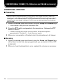
CONVENTIONAL FORMAT (TK-780 series and TK-880 series only)
CONVENTIONAL OPERATION
■ Transmitting
Note: Before transmitting, monitor the channel to make sure it is not already in use. If the
selected channel is programmed with QT (Quiet Talk) or DQT (Digital Quiet Talk), remove the
microphone from the hook to disable QT or DQT, then listen to the channel to make sure nobody
is talking on it. If the selected channel is not programmed with QT or DQT, simply listen to the
channel to make sure nobody is talking on it; in this case, you need not remove the microphone
from the hook.
1 Select the desired group and channel using the Group and Channel keys.
• If the channel is busy, wait until it becomes free.
2 Press the PTT switch and speak into the microphone. Release the PTT
switch to receive.
• For best sound quality at the receiving station, hold the microphone
approximately 1.5 inches (3 ~ 4 cm) from your mouth.
3 When your conversation is finished, return the microphone to its hanger.
■ Receiving
1 Select the desired group and channel using the Group and Channel keys.
(If the Scan function has been programmed, you can switch it ON or OFF
as desired.)
2 When you hear the dispatcher’s voice, readjust the volume as necessary.
12
SCAN
If the Scan function is programmed, groups or channels can be scanned by
pressing the key programmed as Scan. Scan can be used as either Single Scan
or Multi Scan. Single Scan monitors only the channels of a single group. Multi
Scan monitors all channels of every group. When the Scan key is pressed, the
SCN indicator and “-SCAN-” or the revert group/ channel number, appear on the
display and scanning starts.
When a call is received, scanning stops and the group and channel digits appear.
Press the PTT switch and speak into the microphone to respond to the call. The
transceiver will continue scanning after an adjustable time delay, if the PTT
switch is released, and no further signal is received.
When the displayed group is not locked out of the scanning sequence, the add
indicator ( ) will appear on the display.
■ Priority Scan
The priority channel must be programmed in order for Priority Scan to
function.
The transceiver will automatically change to the priority channel when a signal
is received on it, even if a signal is being received on a normal channel.
The
indicator appears when the displayed channel is the priority channel.
2-TONE SIGNALLING
2-Tone Signalling is either activated or deactivated by your dealer.
2-Tone Signalling only opens the squelch when the transceiver receives two
tones corresponding to those set up in the transceiver. When the squelch opens,
you will be able to hear the caller without any further action.
After a correct 2-Tone signal is received and the squelch opens, pressing the key
programmed as Monitor will cancel the connection.
If your dealer programmed Transpond for 2-Tone Signalling, your transceiver will
automatically send an acknowledgment signal to the station that called you with
a correct 2-Tone signal. Transpond does not function when you are called as a
Group call.
If your dealer programmed Tone Alert for 2-Tone Signalling, your transceiver will
emit a beep when the correct 2-Tone signal is received.
Note: This transceiver is only capable of decoding 2-Tone Signals. It cannot encode a 2-Tone
Signal.
13
FleetSync™: ALPHANUMERIC TWO-WAY PAGING FUNCTION
FleetSync™ is an Alphanumeric Two-way Paging Function, and is a protocol
owned by KENWOOD Corporation. FleetSync™ enables a variety of paging
functions on your transceiver, some of which depend on dealer programming.
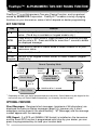
KEY FUNCTIONS
Key
Function
A, #
Press to change the transceiver mode as shown in the diagram
below. (The # key is available on keypad models only.)
SCN
Press while in Stack Mode to toggle between the received message
and the caller’s ID. Press and hold for more than 1 second to delete
the displayed message.
Press while in Selcall or Status Mode to select a station ID or your
tC, Ds
s
transceiver status.
PTT
Press to initiate a call.
(DTMF Use the DTMF keypad to enter Selcall or Status numbers (keypad
Keypad) models only).
Normal Operating Mode
Press A
or receive
a Selcall
Receive
a new
message
Selcall Mode
1
Hold A for
Press 1 second
any key
New Message
Display Mode
Press
A or #
Stack Mode
Press
A or #
Press
A or #
1
Status Mode
Hold A or # for 1 second
Depending on how your dealer programmed the transceiver, Selcall Mode may be skipped or the
transceiver may exit Selcall Mode automatically (as shown by the dash arrow).
OPTIONAL FEATURES
Short Messages: Received short messages (maximum of 48 characters) are
displayed the same as Status messages {page 16}, however only 4 short
messages can be stored in the stack memory. “M” (Message) and the message
number appear with the message.
GPS Report: If a GPS unit (NMEA-0183 format) is installed on the transceiver
and the Send GPS function is programmed onto a key by your dealer, you can
press the programmed key to send your location data.
14
SELCALL (SELECTIVE CALLING)
A Selcall is a voice call to a particular station or to a group of stations.
■ Transmitting
1 Select your desired system and group (or group and channel).
2 Press the A key to enter Selcall Mode.
3 Press the tC or Ds key to select the ID of the station you want to call.
• You can also enter digits by using the DTMF keypad if Manual Dial is enabled.
(Press to erase an incorrect digit.)
4 Press the PTT switch and begin your conversation.
■ Receiving
An alert tone will sound, the transceiver will automatically enter Selcall Mode,
and the calling station’s ID will appear when a Selcall is received.
To respond to the call, press the PTT switch and speak into the microphone.
■ Reviewing Caller IDs in the Stack Memory
The mail icon (
) will flash when a Selcall call is received and stacked.
1 Press and hold the A key for more than 1 second to enter Stack Mode.
• The last received Caller ID is displayed with the Caller ID number. “I” (ID)
appears with the number.
2 Press the tC or Ds key to select the ID you want to view (if more than
one ID is stored in the stack memory).
3 To erase the ID, press and hold the SCN key for more than 1 second.
■ Identification Codes
An ID code is a combination of a 3-digit Fleet number and a 4-digit ID number.
Each transceiver must have its own Fleet and ID number.
• Enter a Fleet number (100 ~ 349) to make a group call.
• Enter an ID number (1000 ~ 4999) to make an individual call in your fleet.
• Enter a Fleet number followed by an ID number to make an individual call in your
desired fleet (Inter-fleet call).
• Select “ALL” Fleet and “ALL” ID to make a call to all units (Broadcast call).
• Select “ALL” Fleet and enter an ID number to make a call to the selected ID in all
fleets (Supervisor call).
Note:
◆ Broadcast and Supervisor calls are programmed functions that cannot be made with a keypad.
◆ The ID range may be limited by programming.
15
STATUS MESSAGE
You can send and receive 2-digit Status messages (10 ~ 79) which may be decided
in your talk group. Messages can contain up to 16 alphanumeric characters.
A maximum of 9 received messages can be stored in the stack memory of your
transceiver. These saved messages can be reviewed after reception. If the stack
memory is full, the oldest message will be erased when a new message is
received. The mail icon ( ) lights when a message is stored in the stack
memory.
Note: All stored messages will be cleared when the transceiver power is turned OFF.
■ Transmitting
1 Select your desired system and group (or group and channel).
2 Press the A key to enter Selcall Mode.
3 Press the tC or Ds key to select the ID of the station you want to call.
• You can also enter digits by using the DTMF keypad if Manual Dial is enabled.
(Press to erase an incorrect digit.)
4 Press the A or # key to enter Status Mode.
5 Press the tC or Ds key to select the status you want to transmit.
• You can also enter digits by using the DTMF keypad if Manual Dial is enabled.
(Press to erase an incorrect digit.)
6 Press the PTT switch to initiate the Status call.
• “COMPLETE” is displayed when the call has been successfully transmitted.
■ Receiving
The mail icon ( ) will flash and a calling ID or text message will appear when
a Status call is received.
• The display alternates between the caller ID and the message.
Press any key to return to Normal Operation Mode.
16
■ Reviewing Messages in the Stack Memory
1 Press and hold the A key for more than 1 second to enter Stack Mode.
• The last received message is displayed with the message number. “S” (Status)
appears with the number.
s key to select the message you want to view (if more
2 Press the tC or Ds
than one message is stored in the stack memory).
3 Press the SCN key to toggle between the message and the caller’s ID.
4 To erase the message, press and hold the SCN key for more than
1 second.
■ Automatic Status Response
If you pre-select a status number and then leave the transceiver in Status
Mode, the transceiver will automatically respond with that status number
when a request from the base station is received. (The base station request
function is optional.)
17
DTMF (DUAL TONE MULTI FREQUENCY) CALLS
MAKING A DTMF CALL
Note: To make a DTMF call, you must have an optional microphone with a DTMF keypad. Ask your
dealer for more information.
There are two methods of making a DTMF call:
•
Manual dialing
•
Store and sending
To make a call by dialing manually:
1 Press and hold the PTT switch.
2 Enter the desired digits using the microphone keypad.
• The corresponding DTMF tones sound each time you press a key.
• If you release the PTT switch, transmit mode will end even if the complete number
has not been sent.
• If your dealer has activated the Keypad Auto PTT function, you need not hold down
the PTT switch while pressing the keys on the keypad. The DTMF code will be
sent automatically when you press a key.
To make a call by storing and sending:
1 Enter the desired digits using the microphone keypad.
• The digits appear on the display as you enter them.
2 After entering the complete number, press the PTT switch.
• If you are using the transceiver in a Conventional mode and Format, the DTMF
code is transmitted after pressing the PTT switch.
• If you are using the transceiver in a Trunking system, the DTMF code is transmitted
after a connection is established. Releasing the PTT switch before a connection is
established will stop the transmission from occuring.
• If you are using the transceiver in a RIC (Repeater Inter-Connect) Trunking system,
the DTMF code is transmitted after a connection with the telephone system is
established. If you press the key programmed as Auto Tel instead of the PTT
switch, the call will automatically connect to the repeater, and the DTMF code will
be transmitted.
Note:
◆ Store and send must first be activated by your dealer in order for it to function.
◆ You can only store up to 16 digits before sending. Entering more than 16 digits will cause an
error tone to sound.
◆ In store and sending mode, if you switch the power OFF before sending the number, the number
will be cleared from memory.
18
DTMF SIGNALLING
Your dealer can program a group or channel with DTMF signalling. When you
receive a call with a code that matches yours, the signalling indicator ( ) will
flash and a tone will sound. Squelch opens and you will hear the call.
Squelch will close when you receive a call with a code that matches your
signalling reset code.
When making a call on a group or channel programmed with a DTMF signalling
code, the signalling indicator will light and the squelch will open.
If your dealer programmed Transpond for DTMF signalling, your transceiver will
automatically send an acknowledgment signal to the station that called you with
the correct DTMF code.
DBD (DEAD BEAT DISABLE)
Depending on how your dealer programs your transceiver, when you receive a
call containing a DBD code, either transmit mode or receive and transmit modes
will be disabled. When a DBD code is received, a tone will sound.
DBD is cancelled when you receive a call with a DBD cancel code.
19
AUDIBLE USER FEEDBACK TONES
The transceiver emits various tones to indicate the transceiver’s operating status.
Please contact your dealer for further information on these tones.
Note: Only the TK-780 series and TK-880 series transceivers support the tone for Conventional
Format.
Conventional
Format
Alert
Yes
Busy
Yes
D BD O n
Yes
DBD Off
Yes
Delay
No
Deny
No
Free System Ring Back Mode/ System Search Mode
No
Group Call
Yes
Individual Call
Yes
Intercept
No
Key Input Error
Yes
Key Press [A]
Yes
Key Press [B]
Yes
Key Press [C]
Yes
Password Agreement
Yes
Power ON
Yes
Pre Alert
Yes
Proceed
No
PTT Release
Yes
Queue
No
Ringing
No
Roll Over
Yes
System Search
No
System Search End
No
Transpond
Yes
Tone
20
Trunking
Format
Yes
Yes
Yes
Yes
Yes
Yes
Yes
Yes
Yes
Yes
Yes
Yes
Yes
Yes
Yes
Yes
No
Yes
Yes
Yes
Yes
Yes
Yes
Yes
Yes
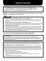
NOTICES TO THE USER
◆ GOVERNMENT LAW PROHIBITS THE OPERATION OF UNLICENSED RADIO
TRANSMITTERS WITHIN THE TERRITORIES UNDER GOVERNMENT CONTROL.
◆ ILLEGAL OPERATION IS PUNISHABLE BY FINE OR IMPRISONMENT OR BOTH.
◆ REFER SERVICE TO QUALIFIED TECHNICIANS ONLY.
SAFETY: It is important that the operator is aware of, and understands, hazards
common to the operation of any transceiver.
◆ EXPLOSIVE ATMOSPHERES (GASES, DUST, FUMES, etc.)
Turn OFF your transceiver while taking on fuel or while parked in gasoline service stations. Do
not carry spare fuel containers in the trunk of your vehicle if your transceiver is mounted in the
trunk area.
◆ INJURY FROM RADIO FREQUENCY TRANSMISSIONS
Do not operate your transceiver when somebody is either touching the antenna or standing within
two to three feet of it, to avoid the possibility of radio frequency burns or related physical injury.
◆ DYNAMITE BLASTING CAPS
Operating the transceiver within 500 feet of dynamite blasting caps may cause them to explode.
Turn OFF your transceiver when in an area where blasting is in progress, or where “TURN OFF
TWO-WAY RADIO” signs have been posted. If you are transporting blasting caps in your vehicle,
make sure they are carried in a closed metal box with a padded interior. Do not transmit while the
caps are being placed into or removed from the container.
One or more of the following statements may be applicable:
FCC WARNING
This equipment generates or uses radio frequency energy. Changes or modifications to this
equipment may cause harmful interference unless the modifications are expressly approved in the
instruction manual. The user could lose the authority to operate this equipment if an unauthorized
change or modification is made.
INFORMATION TO THE DIGITAL DEVICE USER REQUIRED BY THE FCC
This equipment has been tested and found to comply with the limits for a Class B digital device,
pursuant to Part 15 of the FCC Rules. These limits are designed to provide reasonable protection
against harmful interference in a residential installation.
This equipment generates, uses and can generate radio frequency energy and, if not installed and
used in accordance with the instructions, may cause harmful interference to radio communications.
However, there is no guarantee that the interference will not occur in a particular installation. If this
equipment does cause harmful interference to radio or television reception, which can be determined
by turning the equipment off and on, the user is encouraged to try to correct the interference by one
or more of the following measures:
• Reorient or relocate the receiving antenna.
• Increase the separation between the equipment and receiver.
• Connect the equipment to an outlet on a circuit different from that to which the receiver is
connected.
• Consult the dealer for technical assistance.
21
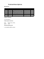
Terminal Descriptions
MIC Modular
NO.
1
2
3
4
5
6
7
8
Name
BLC
PSB
E
PTT
ME
MIC
HOOK
CM
Description
MIC back light control output
B(13.6V)
ground
PTT signal input. Low : TX.
Microphone ground
microphone input
Hook signal input.
MIC key data output
Antenna Terminal
50 Ω impedance
Power input connector
Red :
Black :
Battery-line (13.6V)
GND
External speaker jack
Low impedance(Buffer output)
Impedance
Low Impedance
Low Impedance
High Impedance
1k ohm
High Impedance
Low Impedance
I/O
O
O
I
I
I
O
MANDATORY SAFETY INSTRUCTIONS TO INSTALLERS AND USERS
• Use only manufacturer or dealer supplied antenna.
• Antenna Minimum Safe Distance: 60 cm (2 feet), 50% duty Cycle.
• Antenna Gain: 0 dBd referenced to a dipole.
The Federal Communications Commission has adopted a safety standard for human
exposure to RF (Radio Frequency) energy which is below the OSHA (Occupational Safety
and Health Act) limits.
• Antenna Mounting: The antenna supplied by the manufacturer or radio dealer must not be
mounted at a location such that during radio transmission, any person or persons can
come closer than the above indicated minimum safe distance to the antenna, i.e. 60 cm
(2 feet) , 50% duty Cycle.
• To comply with current FCC RF Exposure limits, the antenna must be installed at or
exceeding the minimum safe distance shown above, and in accordance with the
requirements of the antenna manufacturer or supplier.
• Vehicle installation: The antenna can be mounted at the center of a vehicle metal roof or
trunk lid, if the minimum safe distance is observed.
• Base Station Installation: The antenna should be fixed-mounted on an outdoor permanent
structure. RF Exposure compliance must be addressed at the time of installation.
Antenna substitution: Do not substitute any antenna for the one supplied or recommended
by the manufacturer or radio dealer.
You may be exposing person or persons to excess radio frequency radiation. You may
contact your radio dealer or the manufacturer for further instructions.
Maintain a separation distance from the antenna to person(s) of at least
60 cm (2 feet) , 50% duty Cycle.
“This transmitter is authorized to operate with a maximum duty factor of 50%, in typical
push-to-talk mode, for satisfying FCC RF exposure compliance requirements.”
You, as the qualified end-user of this radio device must control the exposure conditions of
bystanders to ensure the minimum separation distance (above) is maintained between the
antenna and nearby persons for satisfying RF Exposure compliance. The operation of this
transmitter must satisfy the requirements of Occupational/Controlled Exposure
Environment, for work-related use, transmit only when person(s) are at least the minimum
distance from the properly installed, externally mounted antenna. Transmit only when
people outside the vehicle are at least the recommended minimum lateral distance away
from the antenna/vehicle