1
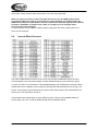
User’s manual
Sirus Pro
MXA 6000
Table of content
1.
Safety instructions........................................................................................................................... 3
2.
Control Elements ............................................................................................................................ 5
2.1.
Microphone channels ............................................................................................................. 5
2.2.
Microphone channel............................................................................................................... 6
2.3.
Monitor Section ...................................................................................................................... 6
2.4.
Master Section ....................................................................................................................... 7
2.5.
Crossfader Section................................................................................................................. 7
2.6.
3D Sourround Effect............................................................................................................... 8
2.7.
Auto BPM Counter ................................................................................................................. 8
2.8.
Internal Effect Processor........................................................................................................ 9
3.
Connections .................................................................................................................................. 10
4.
Installation..................................................................................................................................... 12
4.1.
5.
Audio connections................................................................................................................ 12
Specifications................................................................................................................................ 13
Importeur: .............................................................................................................................................. 14
2 / 14
1. Safety instructions
FOR SAFE AND EFFICIENT OPERATION
Be careful with heat and extreme temperatureAvoid exposing it
to direct rays of the sun or near a heating appliance.
Not put it in a temperature bellow 41°F /5°C, or exceeding 95°F /35°C.
Keep away from humidity, water and dust
Do not place the set in a location with high humidity or lots of dust.
Containers with water should not be placed on the set.
Keep away from sources of hum and noise
Such as transformer motor, tuner, TV set and amplifier.
To avoid placing on un-stable location
Select a level and stable location to avoid vibration.
Do not use chemicals or volatile liquids for cleaning
Use a clean dry cloth to wipe off the dust, or a wet soft cloth for stubborn dirt.
If out of work, contact sales agency immediately
Any troubles arose, remove the power plug soon, and contact with an engineer for repairing,
do not open the cabinet by yourself, it might result a
danger of electric shock.
Take care with the power cable
Never pull the power cable to remove the plug from the receptacle, be sure
to hold the plug. When not using the player for an extended period of time
be sure to disconnect the plug from the receptacle.
CAUTION: To reduce the risk of electric shock, do not remove the top cover (or the rear section).
No user serviceable parts inside; refer servicing to qualified personnel.
WARNING: To reduce the risk of fire or electric shock, do not expose this appliance to rain and
moisture.
3 / 14
(1) Read these instructions.
(2) Keep these instructions.
(4) Follow all instructions.
(5) Do not use this device near water.
(6) Clean only with a dry cloth.
(7) Do not block any ventilation openings. Install in accordance with the manufacturer s instructions.
(8) Do not install near any heat sources such as radiators, heat registers, stoves, or other apparatus
(including amplifiers) that produce heat.
(9) Do not defeat the safety purpose of the polarized or grounding-type plug. A polarized plug
has two blades with one wider than the other. A grounding type plug has two blades and a
third grounding prong. The wide blade or the third prong are provided for your safety. If the
provided plug does not fit into your outlet, consult an electrician for replacement of the obsolete
outlet
(10) Protect the power cord from being walked on or pinched particularly at plugs, extension
cords, and the point at which they exit the unit.
(11) Only use attachments/accessories specified by the manufacturer.
(12) Use only with the cart, stand, tripod, bracket, or table specified by the manufacturer, or
sold with the device. When a cart is used, use caution when moving the cart/ device
combination to avoid injury from stumbling over it.
(13) Unplug this device during lightning storms or when not used for long periods of time.
(14) Refer all servicing to qualified service personnel. Servicing is required when the unit has
been damaged in any way, such as power supply cord or plug is damaged, liquid has been
spilled or objects have fallen into the device, the unit has been exposed to rain or
moisture, does not operate normally, or has been dropped.
4 / 14
2. Control Elements
2.1.
Microphone channels
(1) Use the LINE/CD switch to select the input signal for channel 1. Unlike other channels, channel 1
features two line inputs
(2) You determine the input signals for the channels 2 to 4 with the PHONO/CD i.e. PHONO/LINE
switch (channels 3 and 4). Phono is intended for connecting a turntable. Line i.e CD must be selected
for all other signal sources (e.g. CD or MD players). The input sensitivity of the phono input can be
switched to line level, allowing utmost flexibility (see(41)).
Never connect devices with line level to the highly sensitive phono inputs! The output
level of phono pick-up systems is measured in millivolts, whereas CD players and tape
decks have levels measured in volts, i.e.the level from line signals is up to 100 times
higher than that of the phono inputs
5 / 14
(3) The TRIM control in the CHANNEL section is used to adjust the level of the input signal. The
level meter (5) reads the input level
(4) Each of the input channels features a 3-band equalizer (HI, MID and LOW) with kill characteristic.
Thus, the signal can be attenuated to a much greater extent (-32 dB) than it can be raised
(+12 dB). This function can be very useful when, for example, fading a frequency range
out of a music track.
The overall level also depends on the EQ setting. Thus, you should adjust the equalizer
before setting the input gain with the TRIM control
(5) The 10-digit LED chains display the signal level of the input signals.
(6) Adjust the channel volume using the CHANNEL fader.
2.2.
Microphone channel
(7) The MIC IN connector is the balanced XLR input for your dynamic microphone
(8) Set the volume of the microphone signal with the TRIM control in the MIC section.
(9) There is a 3-band equalizer (HI, MID and LOW, no kill characteristic) in the microphone
section. This allows you to fine-tune your voice to adapt perfectly to your sound
(10) Activate the microphone channel using the MIC ON switch. The channel is active when the
corresponding LED is lit.
(11) The PRO MIXER is equipped with a talkover function, which works very simply: if you speak
into the microphone while a track is running, the volume of the music is automatically reduced,
so that your voice is always in front . The TALK control allows you to determine how much
the music volume is lowered (max. -24 dB). This function can come in handy when your own
voice needs to be prominently heard, as in when making an announcement etc.
2.3.
Monitor Section
The MONITOR signal is your headphones signal, allowing you to listen to music without
affecting the MASTER output signal.
(12) When the MODE switch is in the Split position, channel PFL is located on the left side of
the stereo image, while the Master signal is on the right. In this case, the MIX control (see
below) serves no function. While in Stereo mode, you can use the MIX control to alternate
between MASTER signal and PFL.
6 / 14
(13) When in Stereo mode, the MIX control lets you determine which signal can be heard via the
headphones. When the control is turned to its left-most position (CUE), you hear the headphone
signal only; when the control is turned to its right-most position, you hear the MASTER
signal only. Alternating the MIX control between the two end positions lets you dermine the
relative ratio between the two signals in your headphones.
(14) The LEVEL control determines the volume of the headphones signal
(15) Connect you headphones using the unbalanced PHONES OUT connector. Your headphones
should have a minimum impedance of 32 Ohms.
(16) To select the PFL signal for the headphones, use the MONITOR CUE keys (CH-1 to CH-4,
MASTER, EFFECTS). You can also select multiple signal sources and listen to them simultaneously.
LEDs on corresponding keys are lit when a channel is routed to the headphones.
2.4.
Master Section
(17) The LEVEL METER displays the level of the MASTER signal.
(18) The MASTER fader allows you to adjust the output volume at the MASTER output (see (44)).
(19) The MASTER BALANCE control for the MASTER output is for setting the stereo image
(20) The BOOTH LEVEL control adjusts the output level of the BOOTH output (see (45)).
2.5.
Crossfader Section
(21) ASSIGN A and ASS/GN B selectors let you determine which input signals are routed to
CROSSFADER sides A and B You can also alternate between these two signals by using the
CROSSFADER (see below).
(22) The VCA CONTROLLED CROSSFADER is used to fade between the channels you have
selected (see (21). Like the channel faders, the crossfader section is equipped with a professional 45mm fader
(23) The TIME OFFSET LED indicates the synchronisation of tracks (see chapter 2.7) (24) The VOL
control determines the volume of the headphone signal.
(24) The TEMPO DIFFERENCE LED displays tempo differences between the tracks
(see chapter 2.7).
7 / 14
(25) A 3-band kill switch is available for use with both the left and the right side of the crossfader (KILL
A and KILL B respectively). Kill switches are used to lower three separate frequency
ranges (LOW, MID and HIGH) up to -32 dB. When using the kill switch, the equalizer of ordinary
DJ mixers usually loses its functionality. Not the case with the 5 channel mixer: the EQS
can be used to achieve an even more pronounced lowering of a particular frequency range
(27) The CF CURVE control lets you alter the control characteristic of the crossfader between
linear and logarithmic in an infite number of steps. When set to linear, the crossfader engages
directly proportionally to the fader s incremental movement. When set to logarithmic, the
fader s movement yields higher volume increases as the fader moves farther along its range
of motion.
2.6.
3D Sourround Effect
The 3D surround function is a built-in effect that puts the finishing touch to your music and
turns every gig into a real experience. The widening of the stereo base makes for a livelier,
more transparent sound. You can determine the intensity of the effect by using the SURROUND
control (27), while the ON switch (28) turns the effect on (the respective LED is lit).
2.7.
Auto BPM Counter
The integrated auto BPM counter is an extremely useful feature. It ensures smooth transition
from one track to the next, taking a lot of the guesswork out. It can calculate the various tempos
of tracks in BPM(beats per minute). Both BPM counter sections are identical and both show
the BPM value of the two signals routed to the crossfader. The LEDs located above the DISPLAYs
1-4 (29) indicate which of the four input channels are routed to the respective BPM counter.
The tempo of the track assigned by using the ASSIGN A or ASSIGN B keys is shown in the
respective DISPLAY (30) Several tempo changes in one track would produce a constant display
of various BPM values and thus lead to unnecessary confusion. That s why the beat counter
sections each have a SYNC LOCK button (31) that can be used during the song to limit the
range of possible tempo values. This makes sense if the counter has already calculated a realistic
value. You can do the same thing manually with the BEAT ASS/ST button (32). Pushing
this button at least three times in sync with the song s tempo results in the calculated tempo
appearing in the DISPLAY. The BEAT ASSIST and SYNC LOCK buttons are each equipped
with a LED.
When you have limited the tempo of the tracks on both channels with the SYNC LOCK or
BEAT ASSIST buttons, the difference in tempo from both channels is illustrated in the form of
a ninecharacter message on the TEMPO DIFFERENCE-LED (24). The extent of the difference
in tempo is indicated by a corresponding swing to the right (signal A is slower) or to the Left
(signal B is slower). When the middle LED lights up, the tempi are the same. The TIME OFFSET
LED (23) below that displays the signal A and B synchronisation. Should the middle LED
light up, the tracks are synchronised. Should the display move to the left or right, the channels
8 / 14
are not synchronised. The TEMPO DIFFERENCE and TIME OFFSET displays are only active
if the tempi of both channels have been fixed in one of the ways described.
When no signal is present (or when the signal level is too low), the BPM display shows
only dashes. When the signal is present but can not be identified, the display shows 160
BPM and the shows the said dashes. The beat counter then attempts to get another readout.
Therefore, 160 BPM is no usable value; rather, it is simply an error message whten
the signal can not be analyzed.
To exit the SYNC LOCK or BEAT ASSIST modes, simply push the SYNC LOCK button once
more on both channels.
2.8.
Internal Effect Processor
The built-in digital effects processor of your mixer can process the MASTER signal, the input
channels signal or the microphone signal. Use the SOURCE selector (33) to select the signal
on which you want to run the effects. The PROGRAM display (34) located below shows the effect
presets that can be recalled by turning and then pressing the effect presets that can be (35). The
LEVEL control (36) is used to determine the volume of the effects signal. Use the EFFECTS ON
switch (37) to turn the effects on and off.
Various effects are segmented into seven different groups, offering such standard effects as
reverb, delay, echo etc. As well as additional filter and combination effects.
9 / 14
3. Connections
(38) These are the LINE i.e. CD inputs to connect a tape deck, CD or MD player etc. Unlike other
channels, channel 1 features two line inputs.
(39) The PHONO input for channels 2 to 4 are for connecting a turntable
(40) The GND connectors ground the turntables.
(41) With the PHONO/LINE switch it is possible to switch the input sensitivity of the PHONO inputs
2 to 4 to line level. This allows you to connect a tape deck or a CD player to the PHONO inputs.
(42) The 5 channel mixer features an integrated effects loop for the connection of an external effects
device. The MONITOR signal is taken at the SEND output and routed, fox example, to a
reverb processor. Thus, the signal at the SEND connector is identical to the headphones signal
and is selected with the MONITOR CUE buttons (16).
(43) The externally processed signal is added to the MASTER output signal via the RETURN
connectors. The effect signal volume may only be adjusted at the output control of the effects
device itself.
(44) The MASTER output is for connecting to an amplifier and can be adjusted with the MASTER
fader (18).
Always turn the power amps on last to avoid inrush currents that can easily damage your
speakers. And, to avoid sudden and unpleasant surprises for your ears, make sure there
is no signal at the mixer before turning on the power amps. To be sure, slide all the faders
to the bottom and switch all controls to the zero position.
10 / 14
(45) The BOOTH output gives you an additional option of connecting an amplifier in order to, for
example, feed the signal into your monitors or to bring sound to an extra area. The BOOTH
output level is regulated by using the BOOTH LEVEL control (20) of the MASTER section
(46) Using the TAPE output you can record your music by connecting devices such as tape decks,
DAT recorders etc. Unlike the MASTER output, the output volume is fixed, making it necessary
for you to adjust the input level on the recording device
(47) The POWER switch power the mixer on. You should always make sure that the POWER switch
is in the Off position when initially connecting the unit to the mains.
Please take note: Merely switching the unit off does not mean that it is fully disconnected
from the mains. When not using the unit for prolonged periods of time, please unplug
the unit s power cord from the power outlet.
(48) This is the connector for the power cable. This is where the advantage of a sophisticated internal
power supply can be seen: the pulse behaviour of each amplifying circuit is mainly determined
by the voltage reserves available. Each mixing console is equipped with numerous
operational amplifier (op amps) to process line level signals. Due to limited output of their power
supplies, many mixing consoles show signs of stress when subjected to heavy loads.
But not your mixer: the sound is always clear and transparent.
(49) FUSE HOLDER / VOLTAGE SETTING Before connecting the unit to the mains, ensure that
the voltage setting matches your local voltage. Blown fuses should only be replaced by a fuse
of the same type and rating. On some units, the fuses holder can be switched to on of two positions,
i.e. 230 V and 120 V. Please note: should you desire to operate the unit outside Europe
at 120 V, a higher fuse rating is required.
(50) USB input connector.This is allow the DJ MIXER get the signal from the computer directly,
Channel 1 is used for USB signal adjust .
(51) USB/ Line switch. When you press the button , it changes to Line input , otherwise , it is USB
input.
To disconnect power from main, pull out the main cord plug. When installing the product,
ensure that the plug is easily accessible. If mounting in a rack, ensure that the mains
can be easily disconnected by a plug or by an all-pole disconnect switch on or near
the rack
11 / 14
4. Installation
4.1.
Audio connections
For various applications, you will need a number of different cables. The following illustrations
show how these cables are to be connected. Always make sure to use high-grade cables.
mixer are performed only by qualified personnel. During as well as after installation, sufficient
grounding of both your equipment and persons handling it must be assured. Otherwise,
electrostatic discharge may lead to undesirable operation or permanent damage.
12 / 14
5. Specifications
13 / 14
Importeur:
B & K Braun GmbH
Industriestraße 1
D-76307 Karlsbad
www.bkbraun.com
[email protected]
14 / 14