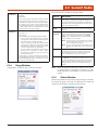
1
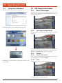
F1
?
F2
F3
F4
F5
F6
M9000
User’s Guide
PN: 769-00005 • May 2012
M9010 is a registered trademark of DAP Technologies. Microsoft and MS-DOS® are
registered trademarks of Microsoft Corporation.
Table of Contents
1.0Introduction . . . . . . . . . . . . . . . . . . . . . . . . . . . . . . . . . . . .
2.9.2
2.9.3
2.9.4
Hide Button . . . . . . . . . . . . . . . . . . . . . . . . . . . . . . . . . . . . . 27
Settings Button . . . . . . . . . . . . . . . . . . . . . . . . . . . . . . . . . . 27
Settings Window . . . . . . . . . . . . . . . . . . . . . . . . . . . . . . . . . 27
2.9.4.1 Communication Tab . . . . . . . . . . . . . . . . . . . . 27
2.9.4.1.1Port . . . . . . . . . . . . . . . . . . . . . . . . 28
2.9.4.1.2 DTR High / RTS High . . . . . . . . 29
2.9.4.1.3 Hardware Pin Events . . . . . . . . . 29
2.9.4.2 Keyboard Tab . . . . . . . . . . . . . . . . . . . . . . . . . . 30
2.9.4.2.1 Interkey Delay . . . . . . . . . . . . . . . 30
2.9.4.2.2 Key Settings . . . . . . . . . . . . . . . . . 30
2.9.4.2.3 Hot Keys . . . . . . . . . . . . . . . . . . . 32
2.9.4.2.4 Keyboard Capture —
External USB Device . . . . . . . . . 36
2.9.4.2.5 Record Key Sequence . . . . . . . . . 39
2.9.4.3 Data Editing Tab . . . . . . . . . . . . . . . . . . . . . . . 40
2.9.4.3.1Wizard . . . . . . . . . . . . . . . . . . . . . 41
2.9.4.3.2 Edit Script . . . . . . . . . . . . . . . . . . 43
2.9.4.3.3 Browse Script Folder . . . . . . . . . 43
2.9.4.4 Misc Tab . . . . . . . . . . . . . . . . . . . . . . . . . . . . . . . 43
2.9.4.4.1 Use Log File . . . . . . . . . . . . . . . . . 43
2.9.4.4.2 Set Password . . . . . . . . . . . . . . . . 44
2.9.4.4.3 Settings Location . . . . . . . . . . . . 44
2.10 Link*One Scripting . . . . . . . . . . . . . . . . . . . . . . . . . . . . . . . . . . . . 45
2.10.1Overview . . . . . . . . . . . . . . . . . . . . . . . . . . . . . . . . . . . . . . . 45
2.10.2 Lua Language . . . . . . . . . . . . . . . . . . . . . . . . . . . . . . . . . . . 45
2.10.3 Script Events . . . . . . . . . . . . . . . . . . . . . . . . . . . . . . . . . . . . 45
2.10.4 Event Methods . . . . . . . . . . . . . . . . . . . . . . . . . . . . . . . . . . . 45
2.10.4.1onStart() . . . . . . . . . . . . . . . . . . . . . . . . . . . . . . . 45
2.10.4.2onEnd() . . . . . . . . . . . . . . . . . . . . . . . . . . . . . . . 45
2.10.4.3 onData(data, length) . . . . . . . . . . . . . . . . . . . . 45
2.10.4.4onHotKey(name) . . . . . . . . . . . . . . . . . . . . . . . 46
2.10.4.5 onKeyboardCapture(name, data) . . . . . . . . . 46
2.10.4.6 onExternalData(data, length) . . . . . . . . . . . . 46
2.10.4.7onTimer() . . . . . . . . . . . . . . . . . . . . . . . . . . . . . 46
2.10.4.8onCTS(status) . . . . . . . . . . . . . . . . . . . . . . . . . . 47
2.10.5 Script Methods . . . . . . . . . . . . . . . . . . . . . . . . . . . . . . . . . . 47
2.10.6 Output/User Feedback . . . . . . . . . . . . . . . . . . . . . . . . . . . . 48
2.10.6.1 beep(frequency, duration) . . . . . . . . . . . . . . . . 48
2.10.6.2 blinkIcon(icon, duration) . . . . . . . . . . . . . . . . 48
2.10.6.3 log(filename, message) . . . . . . . . . . . . . . . . . . . 48
2.10.6.4 messageBox(title, message, type) . . . . . . . . . . 48
2.10.6.5 playSound(filename, options) . . . . . . . . . . . . 49
2.10.6.6 playSystemSound(systemEvent, options) . . . 49
2.10.6.7send(data) . . . . . . . . . . . . . . . . . . . . . . . . . . . . . 49
2.10.6.8 sendSerialData(data, length) . . . . . . . . . . . . . 50
2.10.6.9 sendSubscriberData(data, length) . . . . . . . . . 50
2.10.7Windows . . . . . . . . . . . . . . . . . . . . . . . . . . . . . . . . . . . . . . . 51
2.10.7.1enumWindows(handle) . . . . . . . . . . . . . . . . . . 51
2.10.7.2 findWindow(title, class) . . . . . . . . . . . . . . . . . 51
2.10.7.3getForegroundWindow() . . . . . . . . . . . . . . . . 51
2.10.7.4getWindowClass(handle) . . . . . . . . . . . . . . . . 51
2.10.7.5getWindowClass(handle) . . . . . . . . . . . . . . . . 52
2.10.7.6getWindowText(handle) . . . . . . . . . . . . . . . . . 52
2.10.7.7setForegroundWindow(handle) . . . . . . . . . . 52
2.10.7.8 getWindowText(handle, text) . . . . . . . . . . . . . 52
2.10.7.9 windowOperation(handle, operation) . . . . . 53
2.10.8Clipboard . . . . . . . . . . . . . . . . . . . . . . . . . . . . . . . . . . . . . . . 53
2.10.8.1getClipboardData() . . . . . . . . . . . . . . . . . . . . . 53
2.10.8.2setClipboardData(text) . . . . . . . . . . . . . . . . . . 53
2.10.9 Application Launch . . . . . . . . . . . . . . . . . . . . . . . . . . . . . . 54
2.10.9.1closeAppHandle(handle) . . . . . . . . . . . . . . . . 54
2.10.9.2isAppRunning(handle) . . . . . . . . . . . . . . . . . . 54
7
1.1 User and Product Safety . . . . . . . . . . . . . . . . . . . . . . . . . . . . . . . . 7
1.2 LED and LASER Safety Information . . . . . . . . . . . . . . . . . . . . 7
1.3 FCC Interference Statement . . . . . . . . . . . . . . . . . . . . . . . . . . . . 7
1.4 Industry Canada Statement . . . . . . . . . . . . . . . . . . . . . . . . . . . . 7
1.5 Battery Safety . . . . . . . . . . . . . . . . . . . . . . . . . . . . . . . . . . . . . . . . . . 7
1.6 Warranty Statements . . . . . . . . . . . . . . . . . . . . . . . . . . . . . . . . . . . 8
1.7 Warranty and After Service . . . . . . . . . . . . . . . . . . . . . . . . . . . . . 8
1.8 Europe – EU Declaration of Conformity . . . . . . . . . . . . . . . . . 8
1.9 European Union CE Marking and Compliance Notices . . . 9
1.10Specifications . . . . . . . . . . . . . . . . . . . . . . . . . . . . . . . . . . . . . . . . . 10
2.0 Getting Started . . . . . . . . . . . . . . . . . . . . . . . . . . . . . . 11
2.1
2.2
2.3
2.4
2.5
2.6
2.7
2.8
2.9
What’s In the Package . . . . . . . . . . . . . . . . . . . . . . . . . . . . . . . . . 11
Installing Optional Memory Cards . . . . . . . . . . . . . . . . . . . . . 11
Install the Battery . . . . . . . . . . . . . . . . . . . . . . . . . . . . . . . . . . . . . 13
Charge the Battery . . . . . . . . . . . . . . . . . . . . . . . . . . . . . . . . . . . . 13
2.4.1
2.4.2
Plugging In . . . . . . . . . . . . . . . . . . . . . . . . . . . . . . . . . . . . . . 13
LED Indicators . . . . . . . . . . . . . . . . . . . . . . . . . . . . . . . . . . 14
Operating the Unit . . . . . . . . . . . . . . . . . . . . . . . . . . . . . . . . . . . . 15
2.5.1 Turning the Unit On . . . . . . . . . . . . . . . . . . . . . . . . . . . . . 15
2.5.2 Calibrating the Touchscreen . . . . . . . . . . . . . . . . . . . . . . . 15
2.5.3 Launching an Application . . . . . . . . . . . . . . . . . . . . . . . . . 16
2.5.3.1 Using the Stylus . . . . . . . . . . . . . . . . . . . . . . . . 16
2.5.3.2 Using the Nav Button . . . . . . . . . . . . . . . . . . . 16
2.5.4 Entering Data . . . . . . . . . . . . . . . . . . . . . . . . . . . . . . . . . . . 17
2.5.5 Using the Function Button . . . . . . . . . . . . . . . . . . . . . . . . 17
2.5.5.1 Function Button Key Combinations . . . . . . . 17
2.5.5.2 Function Button with Function Keys . . . . . . 17
2.5.6 Navigating the Display . . . . . . . . . . . . . . . . . . . . . . . . . . . . 18
2.5.6.1 The Task Bar . . . . . . . . . . . . . . . . . . . . . . . . . . . 18
2.5.6.2 The Onscreen Keyboard . . . . . . . . . . . . . . . . . 18
2.5.6.3 Entering the Data . . . . . . . . . . . . . . . . . . . . . . . 18
DAP Configuration Center . . . . . . . . . . . . . . . . . . . . . . . . . . . . . 19
2.6.1 System Info . . . . . . . . . . . . . . . . . . . . . . . . . . . . . . . . . . . . . 19
2.6.2 Display Options . . . . . . . . . . . . . . . . . . . . . . . . . . . . . . . . . .19
2.6.3 Tablet PC Settings . . . . . . . . . . . . . . . . . . . . . . . . . . . . . . . . 19
2.6.3.1 Display Tab – Configure . . . . . . . . . . . . . . . . . 19
2.6.3.2 Display Tab – Calibrate . . . . . . . . . . . . . . . . . . 19
2.6.3.3 Display Tab – Reset . . . . . . . . . . . . . . . . . . . . . 20
2.6.3.4 Other Tab – Handedness . . . . . . . . . . . . . . . . 20
2.6.3.5 Other Tab – Pen and Touch . . . . . . . . . . . . . . 20
2.6.3.5.1 Pen Options Tab –
Configure Double-Tap . . . . . . . . 21
2.6.3.5.2 Pen Options Tab –
Configure Press and Hold . . . . . 21
2.6.3.5.3 Pen Options Tab –
Configure Start Tablet PC
Input Panel . . . . . . . . . . . . . . . . . 22
2.6.3.5.4 Flicks Tab – Navigational . . . . . 23
2.6.3.5.5 Flicks Tab – Sensitivity . . . . . . . 23
2.6.3.5.6 Handwriting Tab . . . . . . . . . . . . . 24
2.6.3.5.7 Touch Tab . . . . . . . . . . . . . . . . . . 24
2.6.3.6 Other Tab – Go to Input Panel Settings . . . . 24
2.6.4 Power Options . . . . . . . . . . . . . . . . . . . . . . . . . . . . . . . . . . . 25
2.6.5 Charger Config . . . . . . . . . . . . . . . . . . . . . . . . . . . . . . . . . . 25
2.6.6Hotkey . . . . . . . . . . . . . . . . . . . . . . . . . . . . . . . . . . . . . . . . . 25
Setting Up Wireless LAN . . . . . . . . . . . . . . . . . . . . . . . . . . . . . . . 26
Using the 1D Barcode Scanner . . . . . . . . . . . . . . . . . . . . . . . . . 26
Setting Up Link One for Reading 1D Laser Barcodes . . . . 26
2.9.1 Unload Button . . . . . . . . . . . . . . . . . . . . . . . . . . . . . . . . . . . 27
3
2.10.9.3 run(program, argument, delay) . . . . . . . . . . . 54
2.10.10 Serial Port . . . . . . . . . . . . . . . . . . . . . . . . . . . . . . . . . . . . . . . 55
2.10.10.1closePort() . . . . . . . . . . . . . . . . . . . . . . . . . . . . . 55
2.10.10.2getDTR() . . . . . . . . . . . . . . . . . . . . . . . . . . . . . . 55
2.10.10.3getRTS() . . . . . . . . . . . . . . . . . . . . . . . . . . . . . . . 55
2.10.10.4openPort() . . . . . . . . . . . . . . . . . . . . . . . . . . . . . 55
2.10.10.5setDTR(status) . . . . . . . . . . . . . . . . . . . . . . . . . 56
2.10.10.6setRTS(status) . . . . . . . . . . . . . . . . . . . . . . . . . . 56
2.10.11Miscellaneous . . . . . . . . . . . . . . . . . . . . . . . . . . . . . . . . . . . 56
2.10.11.1 ean128(data, strict) . . . . . . . . . . . . . . . . . . . . . . 56
2.10.11.2exit() . . . . . . . . . . . . . . . . . . . . . . . . . . . . . . . . . . 56
2.10.11.3exitWindows(options) . . . . . . . . . . . . . . . . . . . 57
2.10.11.4getProfile() . . . . . . . . . . . . . . . . . . . . . . . . . . . . . 57
2.10.11.5getTickCount() . . . . . . . . . . . . . . . . . . . . . . . . . 57
2.10.11.6lockWorkStation() . . . . . . . . . . . . . . . . . . . . . . 57
2.10.11.7setProfile(profile) . . . . . . . . . . . . . . . . . . . . . . . 58
2.10.11.8setTimer(interval) . . . . . . . . . . . . . . . . . . . . . . 58
2.10.11.9sleep(duration) . . . . . . . . . . . . . . . . . . . . . . . . . 58
2.10.12 Notification Area Icon . . . . . . . . . . . . . . . . . . . . . . . . . . . . 58
2.10.13 Migration guide WLinq 3.x to Link*One . . . . . . . . . . . . 59
2.10.13.1 Duplicate String Filter . . . . . . . . . . . . . . . . . . . 59
2.10.13.2 Case Setting . . . . . . . . . . . . . . . . . . . . . . . . . . . . 59
2.10.13.3 Character Translation . . . . . . . . . . . . . . . . . . . 59
2.10.13.4 Send Pre- and Postfix Keys . . . . . . . . . . . . . . . 59
2.10.13.5 Lock Output Window . . . . . . . . . . . . . . . . . . . 59
2.10.13.6 Initialization String . . . . . . . . . . . . . . . . . . . . . 59
2.10.13.7 Filter Unknown Data Strings . . . . . . . . . . . . . 59
2.10.13.8 Input Data Replacements . . . . . . . . . . . . . . . . 60
2.10.13.9Criteria . . . . . . . . . . . . . . . . . . . . . . . . . . . . . . . . 60
2.10.13.10Data Format Output . . . . . . . . . . . . . . . . . . . . 60
2.10.14 Support for Thin Clients, Java Applications,
and Flash Applications . . . . . . . . . . . . . . . . . . . . . . . . . . . 62
2.10.15 Lua Copyright . . . . . . . . . . . . . . . . . . . . . . . . . . . . . . . . . . . 62
2.10.16 Version History . . . . . . . . . . . . . . . . . . . . . . . . . . . . . . . . . . 62
3.2.6.2
FileNameTemplate =
%HOUR%h%MINUTE%m%SECOND%s . 67
3.2.6.3 DefaultImagerMode = Portrait . . . . . . . . . . . 67
3.2.6.4 FlashLightDurationMs = 10000 . . . . . . . . . . 67
3.2.6.5 Func1VirtualKey = 135 . . . . . . . . . . . . . . . . . . 67
3.2.6.6 Func2VirtualKey = 117 . . . . . . . . . . . . . . . . . . 67
3.2.6.7 Func1KeyModifiers = 0 . . . . . . . . . . . . . . . . . . 67
3.2.6.8 Func2KeyModifiers = 0 . . . . . . . . . . . . . . . . . . 67
3.2.6.9 Func1KeySystemWide = 1 . . . . . . . . . . . . . . . 67
3.2.6.10 Func2KeySystemWide = 0 . . . . . . . . . . . . . . . 67
3.2.7[Camera] . . . . . . . . . . . . . . . . . . . . . . . . . . . . . . . . . . . . . . . . 67
3.2.7.1 InactiveTimeBeforeStandbyLevel1 =
10000 . . . . . . . . . . . . . . . . . . . . . . . . . . . . . . . . . 67
3.2.7.2 ActivateDapImagerOnTrigger = OFF . . . . . . 67
3.2.7.3 ShowImageNameOnPreview = OFF . . . . . . . 67
3.2.8[Barcodes] . . . . . . . . . . . . . . . . . . . . . . . . . . . . . . . . . . . . . . .67
3.2.8.1 EnableAutoPreview = ON . . . . . . . . . . . . . . . . 67
3.2.8.2 PreviewWndRect = 0 0 320 240 . . . . . . . . . . . 67
3.2.8.3 UIPolicy = Legacy . . . . . . . . . . . . . . . . . . . . . . 67
3.2.8.4 DefaultFocus = 3733 . . . . . . . . . . . . . . . . . . . . 68
3.2.8.5 Aimer = ON . . . . . . . . . . . . . . . . . . . . . . . . . . . 68
3.2.8.6 DecodeAfterAutofocus = ON . . . . . . . . . . . . . 68
3.2.8.7 MaxNbrResults = 1 . . . . . . . . . . . . . . . . . . . . . 68
3.2.8.8 DecodeTimeoutMs = 1500 . . . . . . . . . . . . . . . 68
3.2.8.9 MaxNbrAttempts = 1 . . . . . . . . . . . . . . . . . . . 68
3.2.8.10 InactiveTimeBeforeStandbyLevel1 =
10000 . . . . . . . . . . . . . . . . . . . . . . . . . . . . . . . . . 68
3.2.8.11 InactiveTimeBeforeStandbyLevel2 =
10000 . . . . . . . . . . . . . . . . . . . . . . . . . . . . . . . . . 68
3.2.8.12 KbWedge = OFF . . . . . . . . . . . . . . . . . . . . . . . . 68
3.2.8.13 AddTab = OFF . . . . . . . . . . . . . . . . . . . . . . . . . 68
3.2.8.14 AddEnter = ON . . . . . . . . . . . . . . . . . . . . . . . . 68
3.2.8.15 Preamble = . . . . . . . . . . . . . . . . . . . . . . . . . . . . 68
3.2.8.16 Postamble = . . . . . . . . . . . . . . . . . . . . . . . . . . . 68
3.2.8.17 InterCharDelay = 0 . . . . . . . . . . . . . . . . . . . . . 68
3.2.8.18 MaxGainWithoutMVLight = 2500 . . . . . . . . 68
3.2.8.19 MinGainWithMovieLight = 1000 . . . . . . . . . 68
3.2.8.20 MaxGain = 4000 . . . . . . . . . . . . . . . . . . . . . . . .68
3.2.8.21 GainStep = 200 . . . . . . . . . . . . . . . . . . . . . . . . . 68
3.2.8.22 IdealGain = 2000 . . . . . . . . . . . . . . . . . . . . . . . 68
3.2.8.23 FlashIntensityStep = 100 . . . . . . . . . . . . . . . . . 68
3.2.8.24 MaxFlashIntensity = 100 . . . . . . . . . . . . . . . . 68
3.2.8.25 MaxShutter = 4000 . . . . . . . . . . . . . . . . . . . . . 68
3.2.8.26 ShutterStep = 260 . . . . . . . . . . . . . . . . . . . . . . . 68
3.2.8.27 IdealShutter = 575 . . . . . . . . . . . . . . . . . . . . . . 68
3.2.8.28 AppendSymbology = OFF . . . . . . . . . . . . . . . 68
3.2.9[OCR] . . . . . . . . . . . . . . . . . . . . . . . . . . . . . . . . . . . . . . . . . . 68
3.2.10[ImagerModes] . . . . . . . . . . . . . . . . . . . . . . . . . . . . . . . . . . 68
3.2.8.1 ModeList =
Portrait,Landscape,Macro,Barcode, . . . . . . . 68
3.2.11[ImagerMode:XXXX] . . . . . . . . . . . . . . . . . . . . . . . . . . . . 68
3.2.11.1 ModeType = 0 . . . . . . . . . . . . . . . . . . . . . . . . . . 68
3.2.11.2 IconID = 142 . . . . . . . . . . . . . . . . . . . . . . . . . . . 68
3.2.11.3 SelectionButtonImageFileName =
res\button-mode-portrait80.png . . . . . . . . . . 68
3.2.11.4 Enabled = ON . . . . . . . . . . . . . . . . . . . . . . . . . . 69
3.2.11.5 AutoFlash = ON . . . . . . . . . . . . . . . . . . . . . . . . 69
3.2.11.6 GpsReportTypes = 1 . . . . . . . . . . . . . . . . . . . . 69
3.2.11.7 PreviewWidth = 640 . . . . . . . . . . . . . . . . . . . . 69
3.2.11.8 PreviewHeight = 480 . . . . . . . . . . . . . . . . . . . . 69
3.2.11.9 StillWidth = 1600 . . . . . . . . . . . . . . . . . . . . . . . 69
3.2.11.10 StillHeight = 1200 . . . . . . . . . . . . . . . . . . . . . . 69
3.0 Operating the Unit . . . . . . . . . . . . . . . . . . . . . . . . . 63
3.1 GPS Instructions . . . . . . . . . . . . . . . . . . . . . . . . . . . . . . . . . . . . . . . 63
3.1.1Requirements: . . . . . . . . . . . . . . . . . . . . . . . . . . . . . . . . . . . 63
3.1.2 Set up to use the GPS . . . . . . . . . . . . . . . . . . . . . . . . . . . . . 63
3.1.3 Integration to Windows 7 . . . . . . . . . . . . . . . . . . . . . . . . . 64
3.2 DAP-Imager Instructions . . . . . . . . . . . . . . . . . . . . . . . . . . . . . . 64
3.2.1 What is DAP-Imager . . . . . . . . . . . . . . . . . . . . . . . . . . . . . 64
3.2.2 Selecting the Right Mode . . . . . . . . . . . . . . . . . . . . . . . . . 64
3.2.3Pictures . . . . . . . . . . . . . . . . . . . . . . . . . . . . . . . . . . . . . . . . . 64
3.2.3.1 How to Take a Picture . . . . . . . . . . . . . . . . . . . 64
3.2.3.2Flash . . . . . . . . . . . . . . . . . . . . . . . . . . . . . . . . . . 64
3.2.3.3Geotagging . . . . . . . . . . . . . . . . . . . . . . . . . . . . 65
3.2.3.3.1 How to enable the GPS . . . . . . . 65
3.2.3.3.2 How to View Geotagging
Data . . . . . . . . . . . . . . . . . . . . . . . 65
3.2.3.4 How to Locate a Saved Picture . . . . . . . . . . . . 65
3.2.3.5 General Options . . . . . . . . . . . . . . . . . . . . . . . . 65
3.2.4Barcodes . . . . . . . . . . . . . . . . . . . . . . . . . . . . . . . . . . . . . . . . 65
3.2.4.1 How to Scan Barcodes . . . . . . . . . . . . . . . . . . . 66
3.2.4.1.1 Using ScannerManager . . . . . . . 66
3.2.4.1.2 Using DAP-Imager as a
Stand-Alone Application . . . . . . . 66
3.2.4.2 Decoder Configuration . . . . . . . . . . . . . . . . . . 66
3.2.5 .INI Configuration File . . . . . . . . . . . . . . . . . . . . . . . . . . . 66
3.2.6[General] . . . . . . . . . . . . . . . . . . . . . . . . . . . . . . . . . . . . . . . .67
3.2.6.1 TargetFolder = %PICTURES%\%YEAR%%MONTH%-%DAY% . . . . . . . . . . . . . . . . . . . 67
4
Convert UPC-E1 to UPC-A : Parameter # 0x26 . . . . . . 81
EAN Zero Extend : Parameter # 0x27 . . . . . . . . . . . . . . . 81
Convert EAN-8 to EAN-13 Type :
Parameter # 0xE0 . . . . . . . . . . . . . . . . . . . . . . . . . . . . . . . . 81
UPC/EAN Security Level : Parameter # 0x4D . . . . . . . .82
UCC Coupon Extended Code : Parameter # 0x55 . . . . 82
5.2 Code 128 . . . . . . . . . . . . . . . . . . . . . . . . . . . . . . . . . . . . . . . . . . . . . . 82
5.2.1 Enable/Disable Code 128 : Parameter # 0x08 . . . . . . . . 82
5.2.2 Enable/Disable UCC/EAN-128 :
Parameter # 0x0E . . . . . . . . . . . . . . . . . . . . . . . . . . . . . . . . 82
5.2.3 Enable/Disable ISBT 128 : Parameter # 0x54 . . . . . . . . . 83
5.2.4 Lengths for Code 128 . . . . . . . . . . . . . . . . . . . . . . . . . . . . . 83
5.3 Code 39 . . . . . . . . . . . . . . . . . . . . . . . . . . . . . . . . . . . . . . . . . . . . . . . 83
5.3.1 Enable/Disable Code 39 : Parameter # 0x00 . . . . . . . . . 83
5.3.2 Enable/Disable Trioptic Code 39 :
Parameter # 0x0D . . . . . . . . . . . . . . . . . . . . . . . . . . . . . . . . 83
5.3.3 Convert Code 39 to Code 32 (Italian Pharma
Code) : Parameter # 0x56 . . . . . . . . . . . . . . . . . . . . . . . . . 83
5.3.4 Code 32 Prefix : Parameter # 0xE7 . . . . . . . . . . . . . . . . . 83
5.3.5 Set Lengths for Code 39 :
Parameter # L1 = 0x12, L2 = 0x13 . . . . . . . . . . . . . . . . . . 83
5.3.6 Code 39 Check Digit Verification :
Parameter # 0x30 . . . . . . . . . . . . . . . . . . . . . . . . . . . . . . . . 84
5.3.7 Transmit Code 39 Check Digit :
Parameter # 0x2B . . . . . . . . . . . . . . . . . . . . . . . . . . . . . . . . 84
5.3.8 Enable/Disable Code 39 Full ASCII :
Parameter # 0x11 . . . . . . . . . . . . . . . . . . . . . . . . . . . . . . . . .84
5.4 Code 93 . . . . . . . . . . . . . . . . . . . . . . . . . . . . . . . . . . . . . . . . . . . . . . . 85
5.4.1 Enable/Disable Code 93 : Parameter # 0x00 . . . . . . . . . 85
5.4.2 Set Lengths for Code 93 :
Parameter # L1 = 0x1A, L2 = 0x1B . . . . . . . . . . . . . . . . . 85
5.5 Code 11 . . . . . . . . . . . . . . . . . . . . . . . . . . . . . . . . . . . . . . . . . . . . . . . 85
5.5.1 Enable/Disable Code 11 : Parameter # 0x0A . . . . . . . . . 85
5.5.2 Set Lengths for Code 11 :
Parameter # L1 = 0x1C, L2 = 0x1D . . . . . . . . . . . . . . . . . 85
5.5.3 Code 11 Check Digit Verification :
Parameter # 0x34 . . . . . . . . . . . . . . . . . . . . . . . . . . . . . . . . 86
5.5.4 Transmit Code 11 Check Digits :
Parameter # 0x2F . . . . . . . . . . . . . . . . . . . . . . . . . . . . . . . . 86
5.6 Interleaved 2 of 5 . . . . . . . . . . . . . . . . . . . . . . . . . . . . . . . . . . . . . 86
5.6.1 Enable/Disable Interleaved 2 of 5 :
Parameter # 0x06 . . . . . . . . . . . . . . . . . . . . . . . . . . . . . . . . 86
5.6.2 Set Lengths for Interleaved 2 of 5 :
Parameter # L1 = 0x16, L2 = 0x17 . . . . . . . . . . . . . . . . . . 86
5.6.3 Interleaved 2 of 5 Check Digit Verification :
Parameter # 0x31 . . . . . . . . . . . . . . . . . . . . . . . . . . . . . . . . 87
5.6.4 Transmit Interleaved 2 of 5 Check Digit :
Parameter # 0x2C . . . . . . . . . . . . . . . . . . . . . . . . . . . . . . . . 87
5.6.5 Convert Interleaved 2 of 5 to EAN-13 :
Parameter # 0x52 . . . . . . . . . . . . . . . . . . . . . . . . . . . . . . . . 87
5.7
Discrete 2 of 5 . . . . . . . . . . . . . . . . . . . . . . . . . . . . . . . . . . . . . . . 88
5.7.1 Enable/Disable Discrete 2 of 5 : Parameter # 0x05 . . . . 88
5.7.2 Set Lengths for Discrete 2 of 5 :
Parameter # L1 = 0x14, L2 = 0x15 . . . . . . . . . . . . . . . . . . 88
5.8 Chinese 2 of 5 . . . . . . . . . . . . . . . . . . . . . . . . . . . . . . . . . . . . . . . . . 88
5.8.1 Enable/Disable Chinese 2 of 5 :
Parameter # 0xF0 0x98 . . . . . . . . . . . . . . . . . . . . . . . . . . . 88
5.9Codabar . . . . . . . . . . . . . . . . . . . . . . . . . . . . . . . . . . . . . . . . . . . . . . . 88
5.9.1 Enable/Disable Codabar :
Parameter # 0x07 . . . . . . . . . . . . . . . . . . . . . . . . . . . . . . . . 88
5.9.2 Set Lengths for Codabar :
Parameter # L1 = 0x18, L2 = 0x19 . . . . . . . . . . . . . . . . . . 89
3.2.11.11 ColorSpace = 16 . . . . . . . . . . . . . . . . . . . . . . . . 69
3.2.11.12 FrameRate = 30.000000 . . . . . . . . . . . . . . . . . 69
3.2.11.13 Shutter = 10000 . . . . . . . . . . . . . . . . . . . . . . . . . 69
3.2.11.14 Brightness = 5000 . . . . . . . . . . . . . . . . . . . . . . . 69
3.2.11.15 GlobalGain = 0 . . . . . . . . . . . . . . . . . . . . . . . . . 69
3.2.11.16 Exposure = 5000 . . . . . . . . . . . . . . . . . . . . . . . . 69
3.2.11.17 FlipMode = 1 . . . . . . . . . . . . . . . . . . . . . . . . . . . 69
3.2.11.18 AutoExposure = ON . . . . . . . . . . . . . . . . . . . . 69
3.2.11.19 LightingMode = 0 . . . . . . . . . . . . . . . . . . . . . . . 69
3.2.11.20 LightingPower = 0 . . . . . . . . . . . . . . . . . . . . . . 69
3.2.11.21 Aimer = OFF . . . . . . . . . . . . . . . . . . . . . . . . . . . 69
3.2.11.22 Compression = ON . . . . . . . . . . . . . . . . . . . . . 69
3.2.11.23 CompressionRatio = 13 . . . . . . . . . . . . . . . . . . 69
3.2.11.24 FocusPosition = 500 . . . . . . . . . . . . . . . . . . . . . 69
3.2.11.25 Autofocus = ON . . . . . . . . . . . . . . . . . . . . . . . . 69
3.2.11.26 WhiteBalancePreset = 0 . . . . . . . . . . . . . . . . . 69
3.2.11.27 ManualWhiteBalance = OFF . . . . . . . . . . . . . 69
3.2.11.28 WhiteBalanceKelvin = 8267 . . . . . . . . . . . . . . 69
3.2.11.29 PreviewToWindow = ON . . . . . . . . . . . . . . . . 69
3.2.12[Permissions] . . . . . . . . . . . . . . . . . . . . . . . . . . . . . . . . . . . . 69
3.2.12.1 Option(More) = 3 . . . . . . . . . . . . . . . . . . . . . . . 69
3.3 Command-Line Options . . . . . . . . . . . . . . . . . . . . . . . . . . . . . . . 70
3.3.1Syntax . . . . . . . . . . . . . . . . . . . . . . . . . . . . . . . . . . . . . . . . . . 70
5.1.16
5.1.17
5.1.18
5.1.19
5.1.20
4.0 Programming the Unit . . . . . . . . . . . . . . . . . . . . 71
4.1 Bar Code Parameter Menus . . . . . . . . . . . . . . . . . . . . . . . . . . . . 71
4.2 Bar Code Settings . . . . . . . . . . . . . . . . . . . . . . . . . . . . . . . . . . . . . 74
4.2.1
4.2.2
4.2.3
4.2.4
4.2.5
4.2.6
4.2.7
4.2.8
4.2.9
4.2.10
4.2.11
4.2.12
4.2.13
4.2.14
4.2.15
Set Default Parameter . . . . . . . . . . . . . . . . . . . . . . . . . . . . 74
Beeper Volume . . . . . . . . . . . . . . . . . . . . . . . . . . . . . . . . . . 74
Beeper Tone . . . . . . . . . . . . . . . . . . . . . . . . . . . . . . . . . . . . . 74
Beeper Frequency Adjustment . . . . . . . . . . . . . . . . . . . . . 74
Laser On Time . . . . . . . . . . . . . . . . . . . . . . . . . . . . . . . . . . . 75
Aim Duration . . . . . . . . . . . . . . . . . . . . . . . . . . . . . . . . . . . 75
Scan Angle . . . . . . . . . . . . . . . . . . . . . . . . . . . . . . . . . . . . . . 75
Power Mode . . . . . . . . . . . . . . . . . . . . . . . . . . . . . . . . . . . . . 75
Triggering Modes . . . . . . . . . . . . . . . . . . . . . . . . . . . . . . . . 76
Time-out Between Same Symbol . . . . . . . . . . . . . . . . . . . 76
Beep After Good Decode . . . . . . . . . . . . . . . . . . . . . . . . . . 76
Transmit “No Read” Message . . . . . . . . . . . . . . . . . . . . . . 76
Parameter Scanning . . . . . . . . . . . . . . . . . . . . . . . . . . . . . . 77
Linear Code Type Security Level . . . . . . . . . . . . . . . . . . . 77
Bi-directional Redundancy . . . . . . . . . . . . . . . . . . . . . . . . 77
5.0 UPC Types . . . . . . . . . . . . . . . . . . . . . . . . . . . . . . . . . . . . . . . 78
5.1 UPC / EAN . . . . . . . . . . . . . . . . . . . . . . . . . . . . . . . . . . . . . . . . . . . . . 78
5.1.1
5.1.2
5.1.3
5.1.4
5.1.5
5.1.6
5.1.7
5.1.8
5.1.9
5.1.10
5.1.11
5.1.12
5.1.13
5.1.14
5.1.15
Enable/Disable UPC-A : Parameter # 0x01 . . . . . . . . . . 78
Enable/Disable UPC-E : Parameter # 0x02 . . . . . . . . . . 78
Enable/Disable UPC-E1 : Parameter # 0x0C . . . . . . . . . 78
Enable/Disable EAN-8 : Parameter # 0x04 . . . . . . . . . . 78
Enable/Disable EAN-13 : Parameter # 0x03 . . . . . . . . . . 78
Enable/Disable Bookland EAN : Parameter # 0x53 . . . 78
Decode UPC/EAN Supplementals :
Parameter # 0x10 . . . . . . . . . . . . . . . . . . . . . . . . . . . . . . . . 79
Decode UPC/EAN Supplemental Redundancy :
Parameter # 0x50 . . . . . . . . . . . . . . . . . . . . . . . . . . . . . . . . 79
Transmit UPC-A Check Digit : Parameter # 0x28 . . . . 80
Transmit UPC-E Check Digit : Parameter # 0x29 . . . . 80
Transmit UPC-E1 Check Digit : Parameter # 0x2A . . . 80
UPC-A Preamble : Parameter # 0x22 . . . . . . . . . . . . . . . 80
UPC-E Preamble : Parameter # 0x23 . . . . . . . . . . . . . . . 80
UPC-E1 Preamble : Parameter # 0x24 . . . . . . . . . . . . . . 81
Convert UPC-E to UPC-A : Parameter # 0x25 . . . . . . . 81
5
5.9.3 CLSI Editing : Parameter # 0x36 . . . . . . . . . . . . . . . . . . . 89
5.9.4 NOTIS Editing : Parameter # 0x37 . . . . . . . . . . . . . . . . . 89
5.10MSI . . . . . . . . . . . . . . . . . . . . . . . . . . . . . . . . . . . . . . . . . . . . . . . . . . . 89
5.10.1 Enable/Disable MSI : Parameter # 0x0B . . . . . . . . . . . . . 89
5.10.2 Set Lengths for MSI :
Parameter # L1 = 0x1E, L2 = 0x1F . . . . . . . . . . . . . . . . . . 90
5.10.3 MSI Check Digits : Parameter # 0x32 . . . . . . . . . . . . . . . 90
5.10.4 Transmit MSI Check Digit : Parameter # 0x2E . . . . . . . 90
5.10.5 MSI Check Digit Algorithm : Parameter # 0x33 . . . . . . 90
5.11RSS . . . . . . . . . . . . . . . . . . . . . . . . . . . . . . . . . . . . . . . . . . . . . . . . . . . 91
5.11.1 Enable/Disable RSS-14 : Parameter # 0xF0 0x52 . . . . . . 91
5.11.2 Enable/Disable RSS-Limited :
Parameter # 0xF0 0x53 . . . . . . . . . . . . . . . . . . . . . . . . . . . 91
5.11.3 Enable/Disable RSS-Expanded :
Parameter # 0xF0 0x54 . . . . . . . . . . . . . . . . . . . . . . . . . . . 91
5.12 Data Options . . . . . . . . . . . . . . . . . . . . . . . . . . . . . . . . . . . . . . . . . . 91
5.12.1 Transmit Code ID Character : Parameter # 0x2D . . . . 91
5.12.2 Prefix/Suffix Values :
Parameter # P = 0x69, S1 = 0x68, S2 = 0x6A . . . . . . . . . . . 92
5.12.3 Scan Data Transmission Format :
Parameter # 0xEB . . . . . . . . . . . . . . . . . . . . . . . . . . . . . . . . 92
5.13 Serial Interface . . . . . . . . . . . . . . . . . . . . . . . . . . . . . . . . . . . . . . . . 93
5.13.1 Baud Rate : Parameter # 0x9C . . . . . . . . . . . . . . . . . . . . . 93
5.13.2 Parity : Parameter # 0x9E . . . . . . . . . . . . . . . . . . . . . . . . . 93
5.13.3 Software Handshaking : Parameter # 0x9F . . . . . . . . . . 93
5.13.4 Decode Data Packet Format : Parameter # 0xEE . . . . . 94
5.13.5 Host Serial Response Time-out : Parameter # 0x9B . . . 94
5.13.6 Stop Bit Select : Parameter # 0x9D . . . . . . . . . . . . . . . . . . 94
5.13.7 Intercharacter Delay : Parameter # 0x6E . . . . . . . . . . . . 94
5.13.8 Host Character Time-out : Parameter # 0xEF . . . . . . . . 94
5.14 Event Reporting . . . . . . . . . . . . . . . . . . . . . . . . . . . . . . . . . . . . . . . 95
5.14.1 Decode Event : Parameter # 0xF0 0x00 . . . . . . . . . . . . . .95
5.14.2 Boot Up Event : Parameter # 0xF0 0x02 . . . . . . . . . . . . . 95
5.14.3 Parameter Event : Parameter # 0xF0 0x03 . . . . . . . . . . . 95
5.15 Numeric Bar Codes . . . . . . . . . . . . . . . . . . . . . . . . . . . . . . . . . . . . 95
5.15.1Cancel . . . . . . . . . . . . . . . . . . . . . . . . . . . . . . . . . . . . . . . . . . 95
7.2 Basic Operations . . . . . . . . . . . . . . . . . . . . . . . . . . . . . . . . . . . . . 108
7.2.1 Start BlueSoleil . . . . . . . . . . . . . . . . . . . . . . . . . . . . . . . . . 108
7.2.2 Search for Other Bluetooth Enabled Devices . . . . . . . .108
7.2.3 Establish Connection . . . . . . . . . . . . . . . . . . . . . . . . . . . . . . 108
7.2.3.1 Start the Service . . . . . . . . . . . . . . . . . . . . . . . 108
7.2.3.2 Initiate the Connection . . . . . . . . . . . . . . . . . 108
7.2.4 Bluetooth Security . . . . . . . . . . . . . . . . . . . . . . . . . . . . . . 109
7.3 Getting Started . . . . . . . . . . . . . . . . . . . . . . . . . . . . . . . . . . . . . . 109
7.3.1 AV Headphone . . . . . . . . . . . . . . . . . . . . . . . . . . . . . . . . . 109
7.3.2 Basic Imaging . . . . . . . . . . . . . . . . . . . . . . . . . . . . . . . . . . 109
7.3.3 Dial-up Networking . . . . . . . . . . . . . . . . . . . . . . . . . . . . . 109
7.3.4FAX . . . . . . . . . . . . . . . . . . . . . . . . . . . . . . . . . . . . . . . . . . . 110
7.3.5 File Transfer . . . . . . . . . . . . . . . . . . . . . . . . . . . . . . . . . . . . 110
7.3.5.1 Connect to a Mobile Phone . . . . . . . . . . . . . 110
7.3.5.2 Share a Folder on Your Computer
with other Bluetooth-Enabled Devices . . . . 110
7.3.5.3 Access a Shared Folder on Another
Bluetooth Enabled Device . . . . . . . . . . . . . . . 111
7.3.6Headset . . . . . . . . . . . . . . . . . . . . . . . . . . . . . . . . . . . . . . . . 111
7.3.7 Human Interface Device . . . . . . . . . . . . . . . . . . . . . . . . . 111
7.3.8 LAN Access . . . . . . . . . . . . . . . . . . . . . . . . . . . . . . . . . . . . 111
7.3.9 Object Push . . . . . . . . . . . . . . . . . . . . . . . . . . . . . . . . . . . . 112
7.3.9.1
Push Objects to a Bluetooth-Enabled
Mobile Phone . . . . . . . . . . . . . . . . . . . . . . . . . 112
7.3.9.2 Receive Objects from a Bluetooth
Enabled Mobile Phone . . . . . . . . . . . . . . . . . . 112
7.3.10 Personal Area Networking . . . . . . . . . . . . . . . . . . . . . . . 112
7.3.10.1 Connecting the PAN User (PANU) . . . . . . 113
7.3.10.2 Configuring the NAP/GN . . . . . . . . . . . . . . . 113
7.3.11Printer . . . . . . . . . . . . . . . . . . . . . . . . . . . . . . . . . . . . . . . . . 113
7.3.12 Serial Port . . . . . . . . . . . . . . . . . . . . . . . . . . . . . . . . . . . . . . 114
7.3.13 Bluetooth Synchronization . . . . . . . . . . . . . . . . . . . . . . . 114
7.4 BlueSoleil User Guides . . . . . . . . . . . . . . . . . . . . . . . . . . . . . . . 115
7.4.1 BlueSoleil Environment . . . . . . . . . . . . . . . . . . . . . . . . . . 115
7.4.1.1 Main Window . . . . . . . . . . . . . . . . . . . . . . . . . 115
7.4.1.1.1 Local Bluetooth Device . . . . . . 115
7.4.1.1.2 Remote Bluetooth Devices . . . 115
7.4.1.1.3 Bluetooth Service Buttons
of Remote Device . . . . . . . . . . . 115
7.4.1.2 Service Window . . . . . . . . . . . . . . . . . . . . . . . 115
7.4.1.3Menus . . . . . . . . . . . . . . . . . . . . . . . . . . . . . . . . 116
7.4.2 Device Configurations 117
7.4.2.1 Hardware Configuration . . . . . . . . . . . . . . . 117
7.4.2.2 Properties Configuration . . . . . . . . . . . . . . . 117
7.4.3 Security Configuration . . . . . . . . . . . . . . . . . . . . . . . . . . 117
7.4.3.1 Pair / Un-pair Devices . . . . . . . . . . . . . . . . . . 117
7.4.3.1.1 How to pair with another
device . . . . . . . . . . . . . . . . . . . . . 117
7.4.3.1.2 How to un-pair with
another device . . . . . . . . . . . . . . 117
7.4.3.2 General Security . . . . . . . . . . . . . . . . . . . . . . . 117
7.4.3.2.1 Security Level . . . . . . . . . . . . . . 117
7.4.3.2.2 Bluetooth Passkey . . . . . . . . . . . 118
7.4.3.2.3 Data Encryption . . . . . . . . . . . . 118
7.4.3.3 Managing Device Pairings . . . . . . . . . . . . . . 118
7.4.3.4 Local Services Security . . . . . . . . . . . . . . . . . 118
7.4.3.4.1 Local Services: . . . . . . . . . . . . . . 118
Appendix A — EAP Types . . . . . . . . . . . . . . . . . . . . . . . . . . . . . . . . . . 119
Appendix B — Encryption Settings . . . . . . . . . . . . . . . . . . . . . . . . . . . 121
6.0 Summit Radio . . . . . . . . . . . . . . . . . . . . . . . . . . . . . . . . . 96
6.1 Summit Client Utility . . . . . . . . . . . . . . . . . . . . . . . . . . . . . . . . . . 96
6.1.1
6.1.2
6.1.3
6.1.4
6.1.5
6.1.6
Main Window . . . . . . . . . . . . . . . . . . . . . . . . . . . . . . . . . . . 96
Profile Window . . . . . . . . . . . . . . . . . . . . . . . . . . . . . . . . . . 97
6.1.2.1 Radio Settings . . . . . . . . . . . . . . . . . . . . . . . . . . 98
6.1.2.2 Preferred Band for 802.11a/g Radio . . . . . . . 98
6.1.2.3 Ad Hoc . . . . . . . . . . . . . . . . . . . . . . . . . . . . . . . . 98
6.1.2.4 Security Settings . . . . . . . . . . . . . . . . . . . . . . . . 99
6.1.2.5 Using Scan to Create a Profile . . . . . . . . . . . . 99
6.1.2.6 EAP Credentials . . . . . . . . . . . . . . . . . . . . . . . 101
6.1.2.7Encryption . . . . . . . . . . . . . . . . . . . . . . . . . . . . 102
6.1.2.7.1 Cisco TKIP . . . . . . . . . . . . . . . . 102
6.1.2.7.2 WPA Migration Mode and
WPA2 Mixed Mode . . . . . . . . . 102
6.1.2.8ThirdPartyConfig . . . . . . . . . . . . . . . . . . . . . . 102
6.1.2.9EAP-FAST . . . . . . . . . . . . . . . . . . . . . . . . . . . . 102
Status Window . . . . . . . . . . . . . . . . . . . . . . . . . . . . . . . . . 102
Diags Window . . . . . . . . . . . . . . . . . . . . . . . . . . . . . . . . . . 103
Global Window . . . . . . . . . . . . . . . . . . . . . . . . . . . . . . . . . 103
PMK Caching . . . . . . . . . . . . . . . . . . . . . . . . . . . . . . . . . . 106
7.0 BlueTooth . . . . . . . . . . . . . . . . . . . . . . . . . . . . . . . . . . . . . . 107
7.1Introduction . . . . . . . . . . . . . . . . . . . . . . . . . . . . . . . . . . . . . . . . . 107
7.1.1
7.1.2
Bluetooth Functions . . . . . . . . . . . . . . . . . . . . . . . . . . . . . 107
Main Window . . . . . . . . . . . . . . . . . . . . . . . . . . . . . . . . . . 107
6
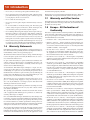
1.0 Introduction
1.1 User and Product Safety
1.0 Introduction
radio communications. However, there is no guarantee that interference
will not occur in a particular installation. If this equipment does cause
harmful interference to radio or television reception, which can be determined by turning the equipment off and on, the user is encouraged to
try to correct the interference by one of the following measures:
• Do not stare into the laser or LED beam directly or shine it into eyes.
• Never use strong pressure onto the screen or subject it to severe impact, as the LCD panel could become cracked and possibility cause
personal injury. If the LCD panel is broken, never touch the liquid
inside because the liquid irritates the skin.
- Reorient or relocate the receiving antenna.
- Increase the separation between the equipment and receiver.
• Although the PDT has passed the test of IP65 standard for water and
dust resistance, avoid prolonged exposure to rain or other concentrated moisture. Such condition exceeds the IP65 standard, and could
result in water or other contaminants entering into the PDT.
- Connect the equipment into an outlet on a circuit different from that
to which the receiver is connected.
- Consult the dealer or an experienced radio/TV technician for help.
• Use only the original approved AC Adapter with the PDT. Use of an
unapproved AC Adapter could result in electrical problems, or even
cause a fire or electrical shock to the user.
FCC Caution: Any changes or modifications not expressly approved by
the party responsible for compliance could void the user’s authority to
operate this equipment. This device complies with Part 15 of the FCC
Rules. Operation is subject to the following two conditions: (1) This device may not cause harmful interference, and (2) this device must accept
any interference received, including interference that may cause undesired operation.
• Do not disassemble the PDT. Servicing should be done by supplier
only. If the PDT or accessories gets damaged due to wrong handling
or unauthorized repair, warranty is void. In case the warranty seals
are broken, warranty is void too.
Complies with 21 CFR 1040.10 and 1040.11 except for deviations pursuant to Laser Notice No. 50, dated June 24, 2007.
• Make regularly back-up of all important data.
• Under no circumstance will supplier be liable for any direct, indirect,
consequential or incidental damages baring out of the use or inability
to use the hardware and software and/or any data loss, even if supplier has been informed about the possibility of such damages.
Specific Absorption Rate (SAR) Information
The SAR Limit of USA (FCC) is 1.6W/kg averaged over one gram of tissue.
The device has been tested against this SAR limit. The highest SAR value
reported under this standard during product certification for properly
worn on the body is 0.75W/kg. This device was tested for typical body-worn
operations with the back of the Tablet PC kept 0 cm from the body. Any
Changes or modifications not expressly approved by the party responsible
for compliance could void the user’s authority to operate the equipment.
• LASER RADIATION: DO NOT STARE INTO BEAM CLASS 2 LASER PRODUCT.
1.2 LED and LASER Safety
Information
1.4 Industry Canada Statement
• M9000 is a Class II LED/Laser Product.
This Class B digital apparatus complies with Canadian ICES-003. Operation is subject to the following two conditions:
• DO NOT STARE at the LED/Laser or shine into eyes.
• Do not allow young children to use the product without adult supervision.
1. This device may not cause interference and
2. This device must accept any interference, including interference that
may cause undesired operation of the device.
• Do not replace/repair the LED/Laser; these are not user replaceable.
• Do not shine the LED/Laser on a shiny reflective surface.
Le présent appareil est conforme aux CNR d’Industrie Canada applicables aux appareils radio exempts de licence.
L’exploitation est autorisée aux deux conditions suivantes : (1)
l’appareil ne doit pas produire de brouillage, et (2) l’utilisateur
de l’appareil doit accepter tout brouillage radioélectrique
subi, même si le brouillage est susceptible d’en compromettre
le fonctionnement.
– RADIATION EXPOSURE STATEMENT –
This equipment complies with FCC radiation exposure limits set
forth for an uncontrolled environment. End users must follow
the specific operating instructions for satisfying RF exposure
compliance. To maintain compliance with FCC RF exposure
compliance requirements, please follow operation instruction
as documented in this manual.
Cet appareil numérique de la classe [B] est conforme à la
norme NMB-003 du Canada.
This transmitter must not be co-located or operating in conjunction with any other antenna or transmitter.
1.5 Battery Safety
The availability of some specific channels and/or operational
frequency bands are country dependent and are firmware programmed at the factory to match the intended destination. The
firmware setting is not accessible by the end user.
– WARNING –
Risk of explosion if battery is replaced by an incorrect type. Dispose of used batteries according to the instructions.
1.3 FCC Interference Statement
Lithium-ion battery packs might get hot, explode, ignite and/or cause
serious injury if exploded by abusive using. Please follow the safety
warnings listed as below:
This equipment has been tested and found to comply with the limits
for a Class B digital device, pursuant to Part 15 of the FCC Rules. These
limits are designed to provide reasonable protection against harmful
interference in a residential installation. This equipment generates uses
and can radiate radio frequency energy and, if not installed and used
in accordance with the instructions, may cause harmful interference to
• Do not throw the battery pack in fire. Do not expose the battery to
high temperatures.
• Do not connect the positive battery pack with negative battery pack
to each other with any metal object (like wire).
7
1.0 Introduction
• Do not carry or store battery pack together with metal objects.
Convention being expressly excluded.
• Do not pierce the battery pack with nails or drills, strike the battery
pack with a hammer, step on the battery pack or otherwise expose it
to strong impacts, shocks or excessive force.
M9000 Series is a registered trademark of DAP Technologies. Microsoft
and MS-DOS® are registered trademarks of Microsoft Corporation.
1.7 Warranty and After Service
• Do not solder onto the battery pack.
Should this Device be malfunctioned, please contact the original retailer
providing information about the product name, the serial number, and
the details about the problem.
• Do not expose battery pack to liquid or allow the battery contacts to
get wet.
• Do not disassemble or modify the battery pack. The battery pack
contains safety and protection measures, which, if damaged, may
cause the battery pack to generate heat, explode or ignite.
1.8 Europe – EU Declaration of
Conformity
• Do not discharge the battery pack using any device except for the specified device. When it is used in devices other than the specified devices, the battery pack can be damaged or its life expectancy reduced.
If the device causes any abnormal current to flow, it may cause the
battery pack to become hot, explode or ignite and cause serious injury.
This device complies with the essential requirements of the R&TTE Directive 1999/5/EC. The following test methods have been applied in order to prove presumption of conformity with the essential requirements
of the R&TTE Directive 1999/5/EC:
• EN 60950-1: 2006 — Safety of Information Technology Equipment
• In the event the battery pack leaks and the fluid gets into one’s eye, do
not rub the eye. Rinse well with water and immediately seek medical
care. If left untreated, the battery fluid could cause damage to the eye.
• EN50371 : (2002-03) — Generic standard to demonstrate the compliance of low power electronic and electrical apparatus with the basic restrictions related to human exposure to electromagnetic fields
(10 MHz - 300 GHz) -- General public
1.6 Warranty Statements
DAP Technologies makes no representation or warranty with respect to
the contents hereof and specifically disclaims any implied warranties of
merchantability or fitness for any particular purpose.
• EN 300 440-1 V1.4.1: (2008-05) — Electromagnetic compatibility and Radio spectrum Matters (ERM); Short range devices; Radio equipment to be used in the 1 GHz to 40 GHz frequency range;
Part1: Technical characteristics and test methods
The information in this manual is subject to change. DAP Technologies
reserves the right to update and modify the M9000 Series, its accessories, and manuals without notice.
• EN 300 440-2 V1.2.1: (2008-05) — Electromagnetic compatibility
and radio spectrum matters (ERM); Wireless microphones in the 25
MHz to 3 GHz frequency range;
No part of this manual may be copied, distributed, transmitted, transcribed, stored in a retrieval system, or translkated in any form or by
any means, whether electronically or manually, without the express
written consent of DAP Technologies.
• EN 301 908-1 V3.2.1: (2007-05) — Electromagnetic compatibility
and Radio spectrum Matters (ERM); Base Stations (BS), Repeaters
and User Equipment (UE) for IMT-2000 Third-Generation cellular
networks; Part 1: Harmonized EN for IMT-2000, introduction and
common requirements, covering essential requirements of article
3.2 of the R&TTE Directive
As manufacturer, DAP Technologies will replace or repair, at its discretion, any products that prove to be defective in either materials or
workmanship, for a period of one year following the purchase date of
the M9000 Series unit and for a period of ninety (90) days following the
purchase date of the M9000 accessories sold by DAP Technologies. The
warranty only covers the materials and workmanship.
• EN 301 489-1 V1.8.1: (2008-04) — Electromagnetic compatibility
and Radio Spectrum Matters (ERM); ElectroMagnetic Compatibility (EMC) standard for radio equipment and services; Part 1: Common technical requirements
This warranty does not cover damages caused by misuse, abuse, or neglect, or occurring during shipping or storage; the warranty does not
also cover any modification or servicing by anyone other than a DAP
Technologies Authorized Service Center.
• EN 301 489-3 V1.4.1 (2002-08) — Electromagnetic compatibility
and Radio Spectrum Matters (ERM); ElectroMagnetic Compatibility (EMC) standard for radio equipment and services; Part 3: Specific
conditions for Short-Range Devices (SRD) operating on frequencies
between 9 kHz and 40 GHz
DAP Technologies cannot be held responsible for any damage caused by
the misuse fo the M9000 Series unit or by any other software or hardware added to the M9000.
• EN 301 489-7 V1.3.1 (2005-11) — Electromagnetic compatibility and
Radio spectrum Matters -(ERM); ElectroMagnetic Compatibility
(EMC) standard for radio equipment and services; Part 7: Specific
conditions for mobile and portable radio and ancillary equipment of
digital cellular radio telecommunications systems (GSM and DCS)
The operating system, MS-DOS®, Windows CE, and all other software
sold or supplied by DAP Technologies are provided as is, without any
warranty, either express or implied.
In no event shall DAP Technologies be liable for any direct damage, indirect damage, or damage of any kind, including but not limited to damages on account of the loss of present or prospective profits arising out of or
in connection with the use or failure of performance of this product. No
claim may be made against DAP Technologies under this head, whether
arising from contractual, extra-contractual, or statutory liability.
• EN 301 489-17 V1.3.2 (2007-06) — Electromagnetic compatibility
and Radio spectrum Matters (ERM); ElectroMagnetic Compatibility
(EMC) standard for radio equipment; Part 17: Specific conditions for
2,4 GHz wide-band transmission systems, 5 GHz high performance
RLAN equipment and 5,8 GHz broadband data transmitting systems
• EN 301 489-19 V1.2.1 (2002-11) — Electromagnetic compatibility
and Radio spectrum Matters (ERM); ElectroMagnetic Compatibility (EMC) standard for radio equipment and services; Part 19: Specific conditions for Receive-Only Mobile Earth Stations (ROMES)
The warranty allowed hereby excludes all other legal warranties related
to the quality of this product or its capacities to fulfill specific purposes,
including all warranties granted by the United States Convention on
Contracts for the International Sale of Goods, the applciation of such
8
1.0 Introduction
operating in the 1,5 GHz band providing data communication
• EN 301 489-24 V1.5.1 (2010-10) — Electromagnetic compatibility
and Radio spectrum Matters (ERM); ElectroMagnetic Compatibility (EMC) standard for radio equipment and services; Part 24: Specific conditions for IMT-2000 CDMA Direct Spread (UTRA and EUTRA) for Mobile and portable (UE) radio and ancillary equipment
• EN 301 489-33 V1.1.1 (2009-02) — Electromagnetic compatibility
and Radio spectrum Matters (ERM); ElectroMagnetic Compatibility
(EMC) standard for radio equipment and services; Part 33: Specific
conditions for Ultra-Wide-Band (UWB) communications devices
• EN 302 065 V1.2.1 (2010-07) — Electromagnetic compatibility and
Radio spectrum Matters (ERM); Short-Range Devices (SRD) using
Ultra- Wide-Band technology (UWB) for communications purposes; Harmonised EN covering the essential requirements of Article 3.2
of the R&TTE Directive
• EN 301 511 V9.0.2 (2003-3) — Global System for Mobile communications (GSM); Harmonised EN for mobile stations in the GSM 900
and GSM 1800 bands covering essential requirements under Article
3.2 of the R&TTE Directive (1999/5/EC)
• EN 301 893 V1.5.1 (2008-12) — Broadband Radio Access Networks
(BRAN); 5 GHz high performance RLAN; Harmonised EN covering
the essential requirements of Article 3.2 of the R&TTE Directive
• EN 300 328 V1.7.1 (2006-02) — Electromagnetic compatibility and
Radio spectrum Matters (ERM); Wide-band transmission systems;
Data transmission equipment operating in the 2,4 GHz ISM band
and using wide-band modulation techniques; Harmonised EN covering essential requirements under Article 3.2 of the R&TTE Directive
• EN 62311:2008 — Assessment of electronic and electrical equipment
related to human exposure restrictions for electromagnetic fields (0
Hz-300 GHz)
• EN 55022:2006/A1:2007 — Information technology equipment —
Radio disturbance characteristics — Limits and methods of measurement
• EN 55024:1998/A2:2003 — Information technology equipment —
Immunity characteristics — Limits and methods of measurement
1.9 European Union CE Marking
and Compliance Notices
Statements of Compliance:
English — This product follows the provisions of the European
Directive 1999/5/EC.
Danish — Dette produkt er i overensstemmelse med det europæiske
direktiv 1999/5/EC.
Dutch — Dit product is in navolging van de bepalingen van Europees
Directief 1999/5/EC.
Finnish — Tämä tuote noudattaa EU-direktiivin 1999/5/EC määräyksiä.
French — Ce produit est conforme aux exigences de la Directive
Européenne 1999/5/EC.
German — Dieses Produkt entspricht den Bestimmungen der Europäischen Richtlinie 1999/5/EC.
Greek — To προϊόν αυτό πληροί τις προβλέψεις της Ευρωπαϊκής
Οδηγίας 1999/5/EC.
Spanish — Este producto cumple las disposiciones de la Directiva
Europea 1999/5/CE.
9
1.0 Introduction
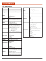
1.10Specifications
Operating System
Windows® Embedded Standard 7,
Windows® CE 6.0 Professional
Processor
Intel® Atom™ E660T 1.3 GHz
Memory
1 GB DDR2 SDRAM (2 GB optional)
Storage
16 GB solid state drive (32 or 64 GB optional)
Display
Sunlight-viewable
Hardened touchscreen
Landscape or portrait orientation
Passive stylus or finger operation
7-inch WVGA (800 x 480)
550 nits
Sensors
Light sensor for auto backlight adjustment
Position sensor (accelerometer) for portrait or landscape screen orientation
Keypad /
Buttons
3-key keypad (enter, navigation, function)
7 programmable keys (touchscreen)
Adjustable keypad backlight
Programmable trigger on underside
Communications
WLAN — Summit 802.11 a/b/g/n
WWAN — Gobi™ 3000: (CDMA, EVDO, UMTS,
GSM, GPRS, EDGE, DTM, HSPA, 3G: 14.4 / 5.76
Mbps, DOrA: 3.1 /1.8 Mbps)
GPS — Gobi™ 3000 (Standalone, XTRA, AGPS)
Zigbee® — Building Automation (BA)
Home Automation (HA)
Smart Energy (SE)
Wireless USB — Video/data
Bluetooth® — v2.1 + EDR Class II (BlueSoleil stack)
Input / Output
Barcode
Scanning
Primary internal:
Power
Li-ion battery pack, 7.4 V, 3000 mAh
Input:
10–20 VDC, 2 A
Dimensions &
Weight
Regulatory
9.0 (L) x 7.3 (W) x 2.3 (H) inches [230 x 185 x 60 mm]
2.96 lb. [1346 g]
FCC Class B
CE
RoHS
WEEE
Laser safety:
A21CFR1040.10
IEC/EN 60825-1
Operating temperature:
-4 to +122 °F [-20 to +50 °C]
Charging temperature:
32 to +104 °F [0 to +40 °C]
Storage temperature:
-22 to +158 °F [-30 to +70 °C]
Drop:
Environment
Multiple 6-foot (1.8-meter) drops to concrete
ESD:
15 kV air discharge, 8 kV direct discharge
Sealing:
Power jack
1x RS-232
1x USB 2.0
Via dock connector:
IP67 certified
Humidity:
1x USB 2.0
1x Ethernet
MIL-STD-810F
5%-95%, non-condensing
Vibration:
Short range barcode: 1D laser
Camera: 5-MP color camera with flash
SD card slot (supports up to 32 GB)
Multi-I/O interface:
Expansion Slots
Li-ion battery, 7.4 V, 3000 mAh
Secondary battery:
2x USB 2.0
1x CAN bus 2.0 (interface only)
1x SDVO (Serial Digital Video Out)
2x RS-232
Audio
Speaker
Intel® HD Audio
3.2 mm stereo headset jack
Software
Windows® Embedded 7:
IE8, IIS 7.0, .NET 3.5, Remote Desktop, SQL, Backup
and Restore, Boot from VHD or USB, Power Management, EWF and FBWF
Windows® CE 6.0 Professional:
ActiveSync, FTP client/server, IE 6.0, Viewers for Microsoft® Office and PDF files, Inbox, Windows Media
Player, Remote Desktop, Terminal Services ,Voice Recorder, Backup and Restore, Barcode Scanner Utility
10
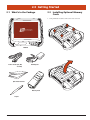
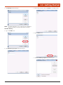
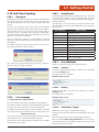
2.0 Getting Started2.0 Getting Started
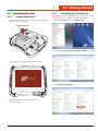
2.1 What’s In the Package
2.2 Installing Optional Memory
Cards
1. Using a flathead screwdriver, remove the screws as shown.
M9010
Power Cords (US, UK,
and EU)
AC Adapter
Quick Start Guide
Battery Pack
Stylus
11
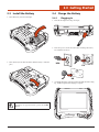
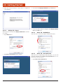
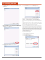
2.0 Getting Started
2. Lift the back cover off.
5. Place the cover back on the unit.
3. Insert the SIM Card into the small slot.
SIM Card
Slot
4. Insert the SD Card into the slot and press in until it locks in place.
6. Insert the screws into their holes and tighten using a flathead screwdriver.
SD Card
Slot
12
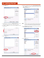
2.0 Getting Started
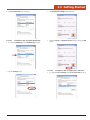
2.3 Install the Battery
2.4 Charge the Battery
1. Insert the battery as shown to the right.
2.4.1
Plugging In
1. Insert the AC adapter into the power input.
2. Insert the power cord into the wall outlet and charge the battery for a minimum of 6 hours.
2. Turn the battery lock wheel clockwise until the battery is locked in
place.
USA
EU
UK
3. A red light will appear on the front of the unit while the unit is charging. It will turn green when charging is complete.
– WARNING –
If the battery is not properly locked into position, the unit WILL
NOT start.
13
2.0 Getting Started
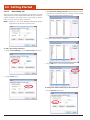
2.4.2
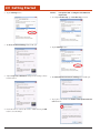
LED Indicators
Red LED
Flashing Green LED
Indicates that batteries are charging.
Idicates that unit is booting, resuming, or hibernating.
Green LED
Yellow LED
Indicates that batteries are charged
Indicates a battery error, including a missing one.
14
2.0 Getting Started
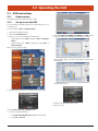
2.5 Operating the Unit
2.5.2
2.5.1
The touchscreen comes pre-calibrated from the factory; however, if the
screen ever needs to be re-calibrated, perform the following:
Turning the Unit On
1. Once the unit is charged, turn the unit on by pressing and releasing
the trigger on the back of the unit.
Calibrating the Touchscreen
1. Open the Start Menu and tap on Control Panel.
Trigger/Scan Key
2. A window entitled Adjust Your Computer’s Settings will open.
2. A DAP splash screen will appear while the OS is loading.
3. Tap the Tablet PC Settings icon.
3. Once the OS has loaded, the desktop will appear.
4. The unit is ready for use.
15
2.0 Getting Started
4.The Tablet PC Settings window will open.
7. Follow the onscreen instructions and the Digitizer Calibration Tool
window will open asking to save the calibration data.
5. Tap the Calibrate button.
8. If the calibration was satisfactory, tap the Yes button.
6. The Calibration window will open.
8. The screen will return to the Tablet PC Settings window.
2.5.3
Launching an Application
2.5.3.1
Using the Stylus
1. Touch the Start Menu Icon
finger or the stylus.
or Start Menu Button
with a
2. When the Start aMenu appears, select an item to launch or navigate
with using a finger or stylus.
2.5.3.2
Using the Nav Button
1. Touch the Start Menu Icon
finger or a stylus.
or Start Menu Button
with a
2. Once the Start Menu appears, use the Nav Button to scroll the list of
items.
3. To select a sub-menu, press the right side of the Nav Button. Pressing
the left side of the Nav Button while in a sub-menu will take you to the
previous menu.
4. Once an item to be selected is highlighted, press the Enter Button to
launch the item.
16
2.0 Getting Started
2.5.4
Entering Data
1. Attach a keyboard to the USB connector on the top of the unit.
2.5.5
Using the Function Button
2.5.5.1
Function Button Key Combinations
This unit provides certain commands through function button combinations. The combinations listed below provide access to the specific
options listed below:
– OR –
2. Tap the Tablet PC Input Panel icon in the task bar at the bottom of
the screen and the Onscreen Keyboard will appear:
+
Shutdown:
+
(Hold until screen shuts off)
2.5.5.2
Reset:
+
Brightness:
+
Tab:
+
Space:
+
+
Function Button with Function Keys
Each Function Key has two states. The first is its programmable function. The second is indicated by an icon representing its function and is
activated as shown below:
4. To close the Onscreen Keyboard, tap either the X or the Tablet PC
Input Panel icon a second time.
5. If the unit is rotated, the screen will go dark, then re-orient the desktop in the following manner:
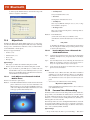
?
17
2
3
6
5
4
Sleep:
+
Product Site:
+
Battery Status:
+
2
Volume:
+
3
Radio Mgmt:
+
4
Camera:
+
5
GPS:
+
6
?
2.0 Getting Started
2.5.6
Navigating the Display
2.5.6.3
2.5.6.1
The Task Bar
To select and open programs, tap Start > All Programs from the task
bar to open a list of available programs. Or if the program has an icon
on the desktop, double-tap it to open it.
The Task bar at the bottom of the screen displays the icon, an icon for the
active program, the current time, and system icons for utilities loaded in
memory. The Task bar includes menu names, buttons, and the keyboard
icon, which opens and closes the soft input panel (SIP). The Task bar allows the user to launch and close programs.
Entering the Data
There are several ways to enter data on the unit once in an application:
• Use the stylus on the touchscreen.
2.5.6.2
• To highlight the desired text, drag the stylus across the desired text,
or double-tap to select one word or triple-tap to select an entire line
or paragraph.
The Onscreen Keyboard
The Onscreen Keyboard can be used to enter data using the stylus.
1. Tap the Keyboard icon in the Task Bar.
• Use the stylus with the onscreen keyboard. Refer to 2.5.4 Entering Data.
• Connect a keyboard to the USB port on the top of the unit. Refer to
2.5.4 Entering Data.
• Use the bar code scanner to enter data. Press the Trigger to initiate
a scan. The scanned data will enter the current application’s open
window. Refer to 2.7.5 Reading 1D laser barcodes.
2. The onscreen keyboard will appear.
For more information on factory installed applications, Refer toSection
3.0 Operating the Unit on page 63.
18
2.0 Getting Started
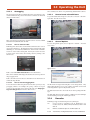
2.6 DAP Configuration Center
2.6.3
To launch the DAP Configuration Center, double-tap the desktop
icon:
Allows the user to adjust, configure, and calibrate the unit’s display.
2.6.3.1
2.6.1
Display Tab – Configure
Allows the user to identify the unit’s screen as the touchscreen.
System Info
1. Tap the Setup button.
This window provides all poertinent system information for the unit.
2.6.2
Tablet PC Settings
2. Tap the screen when prompted with “Touch this screen to identify it
as the touchscreen.”
Display Options
3. Tap the OK button to save changes.
Allows the user to adjust the screen brightness.
2.6.3.2
Display Tab – Calibrate
Allowsw user to calibrate the touchscreen.
1. Tap the Calibrate button.
Tap the Tablet PC Settings button to configure the unit.
19
2.0 Getting Started
2. Follow the onscreen instructions as shown below to complete the
screen calibration.
2.6.3.3
3. To reset the unit’s Display Calibration, tap the Yes button.
4. To exit the window without resetting the unit’s Display Calibration, tap the No button.
Display Tab – Reset
Allows the user to reset the unit’s Display Calibration to their factory settings.
2.6.3.4
Other Tab – Handedness
Allows the user to select between right- and left-handed menus.
1. Tap the Reset button.
2.6.3.5
2.The User Account Control window will open.
Other Tab – Pen and Touch
Allows the user to configure all pen and touch options. To access the
Pen and Touch window, tap the Go to Pen and Touch link. To configure the pen and touch options:
1. Tap the Go to Pen and Touch link.
20
2.0 Getting Started
2.The Pen and Touch window will open.
3.The Double-Tap Settings window will open.
2.6.3.5.1
4. Adjust the Speed and Spatial Tolerance settings, then tap the OK
button.
Pen Options Tab – Configure Double-Tap
1. To configure Double-tap, tap the Double-tap pen action.
2.6.3.5.2
2. Tap the Settings button.
Pen Options Tab – Configure Press and Hold
1. To configure Press and hold, tap the Press and hold pen action.
21
2.0 Getting Started
2. Tap the Settings button.
2.6.3.5.3
Pen Options Tab – Configure Start Tablet PC
Input Panel
1. To configure Double-tap, tap the Double-tap pen action.
3.The Press and Hold Settings window will open.
2. Tap the Settings button.
3. Adjust the Speed and Duration settings and test settings as shown
below, if desired.
3.The Start Input Panel Gesture Settings window will open.
3. Tap to place a checkmark in the Enable start Input Panel Gesture check box.
4. Rotate the unit 90°, wait for the screen to refresh, then tap the OK
button to save the changes.
22
2.0 Getting Started
4. Adjust the Gesture Setting settings, then tap the OK button.
2. Right — Back
3. Up — Drag Up
4. Down — Drag Down
5. Upper Left — Delete
6. Upper Right — Copy
7. Lower Right — Paste
8. Lower Left — Undo
• Customize Flicks — Allows the user to rearrange or customize additional functions if the default functions are not desired.
1. Tap the Customize button.
2.6.3.5.4
Flicks Tab – Navigational
Allows the user to use flicks fo the stylus to perform common actions
quickly and easily. The unit default is that this feature is active. There
are three (3) options available:
• Navigational Flicks — includes four (4) functions:
2. Select the desired functions from each drop-down menu to assign
custom functions to each flick direction.
1. Left — Forward
2. Right — Back
3. Up — Drag Up
4. Down — Drag Down
• Navigational Flicks and Editing Flicks — includes eight (8)
functions:
3. Rotate the unit 90°, wait for the screen to refresh, then tap the OK
button.
2.6.3.5.5
Flicks Tab – Sensitivity
Allows the user to adjust the sensitivity of the stylus flicks. Adjust the
sliders, then rotate the unit 90°, wait for the screen to refresh, then tap
the OK button to save the changes.
1. Left — Forward
23
2.0 Getting Started
2.6.3.5.6
2.6.3.6
Handwriting Tab
Allows the user to choose whether to use Automatic Learning or
not. For more information, tap the Learn about handwriting personalization link at the bottom of the window.
Other Tab – Go to Input Panel Settings
Allows the user to configure the Input Panel Settings. These settings include Handwriting options, Ink to text conversion options, Text
completion options, Insertion options, and Advanced options.
To configure these settings:
1. Tap the Go to Input Panel Settings link.
To save the changes, rotate the unit 90°, wait for the screen to refresh,
then tap the OK button.
2.6.3.5.7
Touch Tab
2. Tap the tab of the topic to be configured.
Allows the user to activate the use of a finger as an input device.
3. Make adjustments as desired.
See section 2.6.3.5.1 for instructions on setting the Double-Tap action. See Section 2.6.3.5.2 for instructions on setting the Press and
Hold action.
4. Rotate the unit 90°, wait for the screen to refresh, then tap the OK
button to save the changes.
Tap the Advanced Options button for additional features for the
Touch Pointer.
To save the changes, rotate the unit 90°, wait for the screen to refresh,
then tap the OK button.
24
2.0 Getting Started
2.6.4
Power Options
2.6.6Hotkey
Allows the user to turn each of the powered components of the unit Off
or On.
Allows the user to modify, add, or delete Hotkeys.
To activate the Modify or Delete a Hotkey:
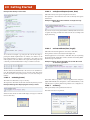
1. Tap a Hotkey.
Also allows the user to set the WWAN to Off, Airplane, or On:
2. Tap the Modify button and the Modify Hotkey window will open.
2.6.5
Charger Config
3. Tap the Down Arrow to select a new function for the key selected.
Allows the user to change the order of the battery order for charging and
and the battery order for usage.
4. Tap the OK button to save the change.
5. Follow the steps 2–4 above, but tapping the Add button to add a new
Hotkey.
25
2.0 Getting Started
2.7 Setting Up Wireless LAN
2.9 Setting Up Link One for Reading 1D Laser Barcodes
The Summit Client Utility (SCU) is an application designed for end users and administrators of mobile devices that use a Summit radio module. For more information about or to initialize SCU, see 6.0 Summit
Client Utility.
To use the scanning function, complete the following steps:
1. If not already removed, remove the protective plastic film from the
barcode reader.
2.8 Using the 1D Barcode Scanner
2. Navigate to: Start Menu > All Programs
1. Launch the data capture application.
2. Aim the 1D Barcode Scanner at the barcode.
3. Press the trigger and the laser reader will activate.
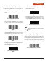
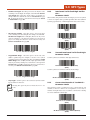
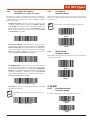
4. Pass the laser reader over the bar code as shown as Correct Scan
below:
Correct Scan:
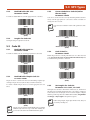
5. When the laser reader accepts the code, a tone will sound, the reader
will deactivate, and the data will appear in the target window of the
application.
6. If the scan is performed incorrectly, as shown below:
Incorrect Scans:
2. Tap on the Freefloat Link One folder.
or the bar code is otherwise unreadable by the scanner, the laser reader will remain active for 10 seconds and no tone will sound. At 10
seconds, the laser scanner automatically deactivates and no data will
have been accepted or entered.
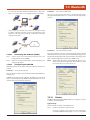
3. Double-tap on the Link One icon. If Link*One is already active, a
small square will be located in the Task Bar at the bottom of the
window.
26
2.0 Getting Started
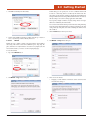
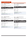
2.9.3
4. The application will launch and the Freefloat Link One main window will open.
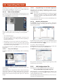
Settings Button
1. Tap the Settings button.
6.The Settings window will open.
NOTE: The main window allows the user to control Link*One by mod-
ifying the settings, setting profiles, and hiding or unloading the
application.
2.9.1
Unload Button
1.Tapping Unload quits the Link One application. Please note that
tapping the red X only minimizes the window to the task bar.
2.9.4
Settings Window
The main window allows the user to control Link*One by modifying
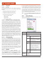
the settings, setting profiles, and hiding or unloading the application.
2.9.4.1
2. To check whether the application is running when the main window
is closed, look for the grey box in the task bar. This indicates that
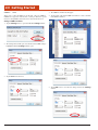
Link One is active.
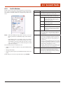
2.9.2
Communication Tab
The Communication tab allows the user to select the communication
settings for the unit. The Port, Speed, Data, Stop, and Parity are the settings for the serial port for Link*One to open and use.
Hide Button
Tapping the Hide button closes the window and minimizes it to the
task bar.
Please note that tapping the red X also minimizes the window to the
task bar.
27
2.0 Getting Started
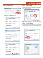
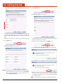
2.9.4.1.1Port
3. The COM Port number list will appear.
Allows user to select the COM port for the unit. The ports COM1 to
COM256 are supported. If the user has a serial port that has a special
name, for example BSP2:, that name can be entered in the Port box.
4. Tap the name of the desired COM Port number to select it and ther
Port COM list will close.
Change a COM Port Name
1. Tap the Settings button to open the Link*One Settings window.
2. The Settings window will open. Note that the current COM setting is
highlighted when the Settings window opens.
2. Tap the Port box down arrow.
5. Tap the OK button to save the new setting and close the Settings
window.
28
2.0 Getting Started
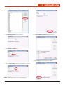
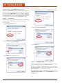
Enter a Custom COM Port Name
2.9.4.1.2
1. Tap the Settings button to open the Link*One Settings window.
When DTR High or RTS High is checked, the corresponding handshake
signal of the serial port will be set. Some serial devices require these to
be set to enable communication.
DTR High / RTS High
2. The Settings window will open. Note that the current COM setting is
highlighted when the Settings window opens.
NOTE: The DTR and RTS handshake signal can be controlled dynami-
cally from a script.
2.9.4.1.3
Hardware Pin Events
In a serial port there are four incoming signals called CTS, DSR, RI,
and DCD. Link*One can be set up to monitor these signals and generate
an event when a signal is changed. An event can be generated when the
signal goes high and/or when it goes low.
1. Tap the Hardware Pin Events button.
3. Type the name of the custom COM port in the Port box.
2. Place check marks next to the signals to be monitired by tapping
with the Stylus.
4. Tap the OK button and the custom COM port name will be saved.
29
2.0 Getting Started
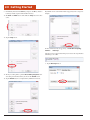
3. When finished, tap the OK button to apply the changes.
2.9.4.2.2
Key Settings
Allows the user to specify key definitions for the keyboard. A key definition is a named key sequence. Key definitions are referred to in an expression passed to the app.send() method which replays the key presses
recorded in the key definition. By default, Link*One defines many of
the standard keys on the keyboard. A key definition can be added, edited, and removed.
If the event is enabled in this dialog, a corresponding method in the
script will be called. The default implementations of these methods send
the signal name and its status (high or low):
To set a key definition:
1. Tap the Key Settings button.
2.9.4.2
Keyboard Tab
Allows the user to customize keyboard settings.
2.9.4.2.1
Interkey Delay
2.The Key Settings window will appear.
The Interkey Delay specifies the delay to be used between each key press
when simulating keyboard data in an application. For example, Microsoft’s Terminal Services client in full screen mode loses key presses if
this is set to zero. This is a global delay. A recorded key sequence may
contain additional delays between key presses.
30
2.0 Getting Started
3. To add a key sequence—for example, Ctrl+A—click the Add button.
7. Tap the Next button.
4.The Add Key Sequence window will open.
8.The Recorded Key Sequence window will open.
5.Enter Ctrl+A in the Name box.
9. Tap the New button to record the key sequence.
6. Tap the curly brackets button to enclose the the key sequence.
NOTE: All key names must be enclosed in curly brackets.
31
2.0 Getting Started
9. Immediately hold down the Ctrl key and press the A key. Release
both keys and the sequence will be held in memory.
Key definitions are used with the method app.send() from a script. For
example:
10.The New and Add buttons dim while the Stop button becomes
active.
11. Tap the Stop button.
For more information about app.send(), see Link*One Scripting.
2.9.4.2.3
Hot Keys
A hot key is a key sequence that when pressed causes the script method
onHotKey() to be called.
1. Tap the Hot Keys button.
12.The key recording will stop and the Record Key Sequence window dialog box will show the key strokes for the Ctrl+A action.
13. Tap the Finish button to complete the key definition and save it.
32
2.0 Getting Started
2.The Hot Keys window will open.
5. Enter a name for the hot key in the Name box (example is F12).
NOTE: By default, Link*One does not contain any hot key definitions.
In the above dialog you can add, edit and remove hot keys.
To Add a Hot Key
3. Tap on the Add button.
6. Tap the Next button.
4.The Add Hot Key Sequence window will open.
7.The Recorded Key Sequence window will open.
33
2.0 Getting Started
8. Tap the New button to record the key sequence.
12.The key recording will stop and the Record Key Sequence window dialog box will show the key strokes for the F12 action.
9. Immediately press and release the F12 key, and the sequence will be
held in memory.
NOTE: The hot key sequence above consists of both the F12 down
10.The New and Add buttons will dim while the Stop button becomes active.
event and the F12 up event. You can remove the up event from
the key sequence to make the hot key feel more responsive but
remember that, if you do so, the F12 up event will be passed to
the application. This is not a problem because most application
reacts to key presses on the down event but it may cause problems in some special circumstances.
13. Tap the Finish button to complete the key definition and save it.
11. Tap the Stop button.
NOTE: A hot key sequence is global in Windows. In the above case, F12
is filtered out from all applications while Link*One is running.
The default implementation of the onHotKey() method looks like this:
It simply enters “Hot Key: <hot key name>”. Of course, hot keys can be
made to do more useful things.
34
2.0 Getting Started
4. Tap on F12[up] to highlight it.
To Delete a Hot Key
1. Tap on a Hot Key sequence component to be deleted. In this example, tap on F12[down] to highlight it.
5. Tap the Remove button.
6.The Record Hot Key window dialog box shall be empty.
2. Tap the Remove button.
7. Tap the Finish button to complete the Hot Key deletion.
3. F12[down] is removed.
8. The following warning will appear:
9.Tap OK and the warning will disappear.
35
2.0 Getting Started
13. Tap the Cancel button to close the Hot Keys window.
10.The Add Hot Key window will reappear with the F12 text still in
the Name box.
14. The F12 sequence is now removed from the Hot Keys list.
2.9.4.2.4
Keyboard Capture — External USB Device
Allows the unit to capture data strings from an external USB-HID device.
A keyboard capture consists of a name, a prefix key sequence, and a
suffix key sequence. It is used to capture data strings from a USB-HID
device (for example a USB connected barcode scanner).
11. Tap the Cancel button and the Add Hot Key Sequence window
will close. The F12 text will also disappear from the Add Hot Key
Sequence window’s Name box.
For this to work, the USB device needs to be configured to send (1) a special key sequence before the data string and (2) a key sequence that terminates the data string. Please note that the prefix sequence should be
chosen with care. All the keys in the keyboard capture’s prefix sequence
will be filtered from regular keyboard input until a mismatch is found.
When a data string is captured by a keyboard capture, the script method
onKeyboardCapture() is called.
To perform a keyboard capture:
1. Attach a USB-HID device and plug it in.
2. Turn the USB-HID device on.
3. Tap the Keyboard Capture button.
12.The Add Hot Key Sequence window will close.
36
2.0 Getting Started
4.The Keyboard Captures window will open.
5. As an example, the name of a USB device is entered into the Name
box to begin the keyboard capture definition for that device.
6. Tap the Next button.
NOTE: By default, Link*One does not contain any keyboard captures.
In the above dialog box, you can add, edit, and remove keyboard captures.
3. click on the Add button.
4.The Add Keyboard Capture window will open.
7.The Record Keyboard Capture window will open.
37
2.0 Getting Started
8. Tap the New button
12.The key recording will stop and the Record Keyboard Capture - Prefix window dialog box will show the key strokes for the
Shift+Control+A action.
9. Immediately press and release the Shift+Control+A keys on the
attached keyboard, and the sequence will be held in memory.
NOTE: All the key strokes the scanner generates when reading a bar-
code gets recorded: prefix, barcode data, and suffix. In the dialog above, the line directly after the prefix has been selected.
10.The New and Add buttons will dim while the Stop button will
become active.
13.Tap the Remove button repeatedly to remove the key events for the
barcode data and suffix from the list.
11. Tap the Stop button.
14.Tap the Next button.
38
2.0 Getting Started
15.The Record Keyboard Capture - Suffix window will appear.
19.Tap the OK button to save the changes.
20.Open Notepad and test the keyboard capture.
16. Repeat steps 8 through 13 making sure to delete the key events for the
barcode data and the prefix data from the list leaving only the suffix
data.
NOTE: If you only get the barcode contents, the keyboard capture is
17.Tap the Finish button to complete the keyboard capture definition.
18.The Suffix window will close and the new Keyboard Captures ID
will be displayed in the Keyboard Captures window.
not working. This is probably because a mistake was made in
the setup of the scanner or the prefix sequence.
If you don’t get anything and the keyboard seems to have
stopped working, then the suffix sequence is probably wrong.
The default script method onKeyboardCapture() looks like this:
2.9.4.2.5
Record Key Sequence
The Record Key Sequence dialog is used for recording key definitions, hot keys, and prefix and suffix of keyboard captures.
39
2.0 Getting Started
2.9.4.3
3.The Select Data String Terminator window will open and display a library of terminator characters with their associated ASCII
codes in both decimal and hexidecimal notation.
Data Editing Tab
Allows the user to add data string termination to data strings. The Data
String Termination setting tells Link*One which character or character
sequence terminates a data string received on the serial port. Alternatively, you can use a timeout value as a terminator.
NOTE: If Timeout is set to 30 ms, Link*One will terminate an input
string when no data has been received for 30 ms.
4. Tap the desired terminator to highlight it.
To add a data string terminator
1. Under the Data Editing tab, tap the Character(s) radio button.
5. Tap the OK button to select the desired terminator.
2. Tap the Select button.
To change the millisecond delay for the terminator
6. Tap the Timeout radio button.
40
2.0 Getting Started
7. The millisecond delay box will activate.
In this dialog you can specify zero or more conditions that should
be met for a data string before it is edited by the wizard rules. If a
data string doesn’t meet the conditions and the check box Filter Data
Strings is checked, the data string is filtered. If the check box is cleared,
the data string is sent to the receiving application unmodified.
If you specify a length condition, any data strings shorter or longer
will not be modified by the wizard rules.
You can enter texts that should be present in the data string. Entering
00 in the At Start field will check for 00 in the beginning of the data
string. Then any string that starts with something else will not meet
the condition.
3. Click the Next button when you are done.
8. Set the desired millisecond delay by either using the up or down arrows, or by entering a number directly in the box.
4.The Wizard – Strip window will open.
2.9.4.3.1Wizard
Enable the user to define a simple setup that matches and modifies a
data string. The wizard consist of four different parts, Trig, Strip, Replace, and Add. It is only intended to be used for very simple tasks. For
more advanced tasks, you need to use the scripting language.
To start the wizard:
1. Tap on the Wizard button.
5. Select one of two choices:
2.The Wizard – Trig window will open.
• Stripping a certain number of characters at the start and/or the
end of the data string, or
41
2.0 Getting Started
8. Tap the Next button.
• Removing one or more texts at the indicated positions of the data
string.
9.The Wizard – Add window will open.
For example, if 00 is specified in the field At Start and the data string
is 0012345, the resulting output will be 12345. However, if the data
string is 9912345, nothing will be removed from the start of the data
string.
If all fields are left empty, no text will be stripped from the data string.
6. Tap the Next button.
This window allows the user to enter texts that need to be added to
the data string at the start or the end.
10. When text entry is complete, click on the Finish button.
7.The Wizard - Replace window will open.
11.The Freefloat Link*One Wizard Script window will appear.
12.Tap the Yes button to confirm that a wizard script should be created.
NOTE: This window allows the user to enter up to three text replacements. Enter the text to be replaced in one of the Search for
fields, and then enter the text to replace it with in the corresponding Replace with field.
The wizard script is a Lua script and can be modified manually afterwards if, for example, the need to add more advanced conditions
or modifications arises.
NOTE: The wizard script is overwritten each time the wizard is run.
42
2.0 Getting Started
2.9.4.3.2
Tap the OK button to save all changes.
Edit Script
Opens the Link*One script. The name of the script file is Script.txt
and it is opened in the associated program, normally Notepad.
To edit a script:
1. Tap the Edit Script button.
2.9.4.4
Misc Tab
2.9.4.4.1
Use Log File
2.A Notepad window will open.
3. Edit the script as desired.
4. When finished, tap File > Save to save the script.
If all the internal messages and events in Link*One are to be written to a
log, check the setting Use Log File, and enter a valid path and filename
in the edit box. The log file is mostly used for troubleshooting a script.
Alternatively, the text editor SciTE knows the syntax of Lua. It might be
useful when writing Link*One scripts.
2.9.4.3.3
Browse Script Folder
Opens Windows Explorer in the folder that contains the script, configuration, and the license file. For more information about scripting in
Link*One, see the topic Link*One Scripting.
• To hide Link*One’s main window on startup, check On Startup in
the Hide Window area.
• To hide Link*One’s main window when serial data is received, check
On Incoming Data in the Hide Window area.
When a value greater than 0 is entered into onTimer Interval, the
script method onTimer() will be called once during the specified time
interval. For example: if you enter the value 3000, onTimer() will be
called once every third second. Please take care when choosing a value
here, if 1 ms is entered, onTimer() will be called 1000 times per sec43
2.0 Getting Started
ond. This could make a PC unresponsive. Of course this will be highly
dependant on what code the onTimer() method contains.
To remove a password:
1. Tap the Set Password button to open the Set Password window.
When the option Autostart is checked, Link*One will start automatically when Windows is launched. Link*One will then be started with
the profile for which Autostart was activated . If there are two profiles—one serving COM1 and the other serving COM2—Autostart
can be checked for each of those profiles. One instance of Link*One will
be started at login for every profile that has Autostart checked.
2.9.4.4.2
Set Password
Allows the user to set a password that is required when exiting Link*One
and when clicking on the Settings... button in the main window.
To set a password:
1. Tap the Set Password button.
2. Delete the text in the Password box.
2. Enter a password into the Password box.
3. Tap the OK button.
3. Tap the OK button to save the password.
2.9.4.4.3
Settings Location
A Link*One configuration consist of mainly two parts, the settings (serial port configuration, hot keys, etc.) and the script file(s).
The settings are file-based to enable different users on the same PC to
share the same Link*One configuration. The configuration is stored in
the file Config.dat. Do not edit this file manually.
To determine where script and configuration files are located, click on
the Browse Script Folder button in the Data Editing tab of the
Settings window.
44
2.0 Getting Started
2.10 Link*One Scripting
2.10.3
2.10.1Overview
When things happen in Link*One, for example a hot key or a data string
is received on the serial port, an event is generated. This results in a
script method being called. The methods called when events happen are
called event methods.
Link*One has an embedded script language called Lua. When Link*One
receives data from a device, a hot key is pressed etc. certain methods in
the script are called. The code in these scripts determines what action
is taken.
Script Events
The table below is an overview and short description of all the different event methods. For a more detailed explanation, see the topic Event
Methods below.
The name of the script file is Script.txt and is placed in the Link*One
application data folder. The location of this folder varies depending on
what operating system you are using. If you need to make a backup of
the script or copy it to another PC, click on the Browse Script Folder...
on the Misc tab in the Settings dialog. Windows Explorer is opened and
displays the contents of the script folder.
Event Handler
When you edit the script, remember to restart Link*One to recompile
the script or use the faster alternative of entering the Settings dialog and
then exiting it.
If you make a mistake, for example create a syntax error, an error message is displayed when the script is compiled:
onStart
Link*One is started
onEnd
Link*One is exited
onData
A data string is received on the serial port
onHotKey
A hot key is pressed
onKeyboardCapture
A data string is received from a HID device
onExternalData
A data string is received from an external
application
onTimer
The timer interval has elapsed
onCTS
Status change on CTS
onDSR
Status change on DTR
onRI
Status change on RI
onDCD
Status change on DCD
2.10.4
Also, some errors can appear when the script is running, so called runtime errors. Here are a couple of examples:
When Called
Event Methods
In this topic all the event methods are explained in detail.
2.10.4.1onStart()
This method is called when Link*One is started. It is also called when
you exit the Settings dialog.
This method receives no arguments.
Example: Beep on start
2.10.4.2onEnd()
Called when Link*One is exited. It is also called when you enter the
Settings dialog.
This method receives no arguments.
2.10.2
Lua Language
Example: Beep on exit
From http://www.lua.org/about.html:
Lua is a powerful, fast, light-weight, embeddable scripting language.
Lua combines simple procedural syntax with powerful data description
constructs based on associative arrays and extensible semantics.
2.10.4.3
Put simply, Lua is what makes data processing in Link*One very flexible
and powerful. The reference manual for Lua can be found at the Lua site:
onData(data, length)
Called when a data string is received from the serial port.
This method receives the data string in data and the length of the string
in length.
http://www.lua.org/
There is also a printed book on the Lua language, called Programming
in Lua, which is more accessible than the reference manual.
Data may contain binary characters including the null character.
Please note that if the Data String Termination is set to be a character and that character does not match the terminator used by the serial
device, this method is never called.
Apart from Lua and its built-in language, Link*One exposes a number
of useful methods to the script.
45
2.0 Getting Started
2.10.4.5
Example: Hex dump of serial data
onKeyboardCapture(name, data)
Called when a keyboard capture string has been received.
The arguments to this method are the name of the keyboard capture
and the data.
Example: Display the name and data of a keyboard capture event
If you have a keyboard captured defined called My USB Scanner and
it captures the string 73105541 the method in the above example will
display this dialog:
2.10.4.6
onExternalData(data, length)
Called when an external application sends data to Link*One.
The arguments are the received data and the length of it.
To test the above example, copy and paste the code into the script replacing the default implementation of onData(). Use Timeout as the
Data String Terminator. Connect a serial device to the serial port and
make it generate some data. Below is the output when reading a barcode
containing “W1711010814107013621” using a serial barcode reader:
External applications can send data to Link*One. They do it by finding
the window handle of Link*One’s window and then send a WM_COPYDATA message to the window.
Example: Display data and length sent to Link*One from
an external application
The last character 0d (hexadecimal) is the same as 13 in decimal notation. The ASCII character with code 13 is carriage return. This means
the barcode reader is using carriage return (<cr>) as its data string terminator.
2.10.4.4onHotKey(name)
This feature makes it possible to create an application that integrates
tightly with Link*One. For example, the code in onExternalData() could
relay the data to a scanner to make it beep, initiate a scan, configure it etc.
This method is called when you press a hot key.
The argument to this method is the name of the hot key that was pressed.
Example: Message box displaying the hot key’s name
2.10.4.7onTimer()
Called periodically at the specified timer interval.
This method receives no arguments.
When executed, the above method will display a message box with the
name of the hot key:
46
2.0 Getting Started
In the example above, the onTimer Interval has been set to 3000 milliseconds (3 seconds). This means that the onTimer() script method will
be called once every three seconds.
Windows
Method
Description
enumWindows
Enumerates all windows
findWindow
Finds a window with the specified title and/
or class
getForegroundWindow
Gets the handle of the foreground window
getWindowClass
Gets the class name of a window
getWindowText
Gets the title of a window
setForegroundWindow
Sets a window to be the foreground window
2.10.4.8onCTS(status)
setWindowText
Sets the title of a window
This method is called when the hardware handshake signal changes
state.
windowOperation
Executes a window operation
This method can be used for adding timeout logic to a solution.
Example: Output a time stamp to the active application at
the onTimer interval
The argument status is true when the signal goes high and false when
the signal goes low.
Clipboard
Method
Description
This description also applies to onDSR, onRI, and onDCD.
getClipboardData
Gets the text on the clipboard
Example: Outputs the state of CTS when it is changed
setClipboardData
Sets the text on the clipboard
Application Launch
2.10.5
Method
Description
closeAppHandle
Closes the application handle
isAppRunning
Determines if an application is still running
run
Starts a program
Script Methods
Serial Port
Method
Lua is a generic script language and has methods to manipulate string,
tables, files, and so on. However, it does not contain any methods to retrieve the title of a window, simulate keys etc. So in order to activate an
application window, send key strokes and similar operations, a number
of internal methods in Link*One have been exposed to the embedded
Lua script engine.
The tables below offers an overview of the methods. The methods have
been grouped into areas of interest for easier reference. Below the tables
there is a reference section with a detailed description of each method.
Description
closePort
Closes the serial port
getDTR
Gets the status of the DTR signal
getRTS
Gets the status of the RTS signal
openPort
Opens the serial port
setDTR
Sets the status of the DTR signal
setRTS
Sets the status of the RTS signal
When these methods are used in a script, you need to prefix them with
“app.”, for example app.sleep( 100 ).
Miscellaneous
Method
Output/User Feedback
Description
ean128
Parses the contents of a GS1-128/UCC/EAN128 code
Beeps with the internal PC speaker
exit
Exits Link*One
blinkIcon
Changes the color of the notification area
icon
exitWindows
Either logs off the current user, shuts down
the PC, or shuts down and restarts the PC
log
Writes a text line to a log file
getProfile
Gets the current Link*One profile
messageBox
Displays a message box
getTickCount
playSound
Plays a sound file
Gets the number of milliseconds elapsed
since the system was started
playSystemSound
Plays a sound associated with a system
event
lockWorkStation
Locks Windows
setProfile
Sets the current profile
send
Sends keyboard data
setTimer
Sets the script timer
sendSerialData
Sends serial data to the COM-port
sleep
Delays the script for some time
sendSubscriberData
Sends data to subscribers
Method
beep
Description
47
2.0 Getting Started
2.10.6
2.10.6.1
Output/User Feedback
2.10.6.3
beep(frequency, duration)
2.10.6.3.1Description
Writes the message to the specified log file. Note that logging with this
method from the script is separate from the built-in logging facility.
2.10.6.1.1Description
Makes the internal PC speaker beep with the specified frequency and
duration.
2.10.6.3.2Arguments
2.10.6.1.2Arguments
Argument
log(filename, message)
Argument
Type
Description
frequency
Number
The frequency of the beep in Hertz.
duration
Number
The duration of the beep in milliseconds.
Type
Description
filename
String
The path and name of the log file to
write to.
message
String
The log message to write.
2.10.6.3.3Returns
2.10.6.1.3Returns
Nothing.
true if successful, false otherwise.
2.10.6.3.4Example
2.10.6.1.4Constants
true if successful, false otherwise.
2.10.6.1.5Example
2.10.6.4
messageBox(title, message, type)
2.10.6.4.1Description
2.10.6.2
blinkIcon(icon, duration)
Displays a message box with the specified title and message. The type
argument specifies the number and type of buttons used.
2.10.6.2.1Description
2.10.6.4.2Arguments
Changes the notification icon color for the specified duration. After the
duration has elapsed the icon will return to the default color grey.
Argument
The operation is asynchronous, in other words, if blinkIcon is called
again before the duration for the first call has elapsed, the new icon is set
immediately by the second call.
2.10.6.2.2Arguments
Argument
Type
Description
icon
Number
The icon color index.
duration
Number
The duration in milliseconds the color
should be displayed before restoring the
default color.
Type
Description
title
String
The message box title.
message
String
The message to be displayed.
type
Number,
optional
The type of buttons to use.
2.10.6.4.3Returns
A value from the constants in mbResults (see below) indicating the button clicked.
2.10.6.4.4Constants
Use one of the following constants for the type argument:
2.10.6.2.3Returns
Nothing.
2.10.6.2.4Constants
2.10.6.2.5Example
The possible return values are:
Please note the delay in the loop is needed to display each icon color for
half a second.
48
2.0 Getting Started
2.10.6.4.5Example
2.10.6.6.4Constants
Use one of the following values for the systemEvent argument:
2.10.6.5
The possible values of the options argument:
playSound(filename, options)
2.10.6.5.1Description
Plays the sound specified by the filename argument.
2.10.6.5.2Arguments
Argument
Type
Description
filename
String
The path and filename of the sound file.
options
Number
Specifies the behavior for the sound playback. Use the constants in soundOptions.
2.10.6.6.5Example
2.10.6.5.3Returns
true if successful, false otherwise.
2.10.6.5.4Constants
2.10.6.7send(data)
2.10.6.7.1Description
Sends keyboard data.
2.10.6.7.2Arguments
Argument
2.10.6.5.5Example
data
Type
String
Description
The data to send.
The argument data is a string consisting of text, key names, and Unicode
characters.
Argument
Type
Description
text
“Rob was
here”
Regular characters.
Key Name
“{Enter}”
Key names corresponds to the keys
defined in the dialog Key Settings.
2.10.6.6.1Description
Unicode
“{65}”
Character in Unicode decimal notation.
Plays the sound specified by the given system event. Different system
events can be mapped to sound files in the Control Panel.
Unicode
“{0x0041}”
Character in Unicode hexadecimal
notation.
2.10.6.6
playSystemSound(systemEvent, options)
2.10.6.6.2Arguments
Argument
2.10.6.7.3Returns
Type
Nothing.
Description
systemEvent
Number
The ID of the system event.
2.10.6.7.4Constants
options
Number
Specifies the behavior for the sound playback. Use the constants in soundOptions.
None.
2.10.6.6.3Returns
true if successful, false otherwise.
49
2.0 Getting Started
2.10.6.9
2.10.6.7.5Example
sendSubscriberData(data, length)
2.10.6.9.1Description
Sends data to subscribers.
If there are no subscribers, calling this method has no effect.
2.10.6.9.2Arguments
Argument
Note:
• When you want send() to send the characters \ and { you need
to escape those with a backslash. There is a helper method called
escapeData() in the supplied file extra.lua.
The data to send to the COM-port.
length
Number
The number of characters of data that
should be sent.
2.10.6.9.3Returns
Nothing.
• When sending data to certain applications they might miss key
presses if the key events are sent too fast or too early. You may
need to increase the setting Interkey Delay and/or intersperse
calls to send() with calls to sleep() or findWindow() depending on
the situation.
None.
2.10.6.9.4Constants
2.10.6.9.5Example
sendSerialData(data, length)
2.10.6.8.1Description
Sends serial data to the COM-port.
Note that Link*One needs to be configured to use a COM-port for this
method to work.
2.10.6.8.2Arguments
Argument
Type
Description
data
String
The data to send to the COM-port.
length
Number
The number of characters of data that
should be sent.
2.10.6.8.3Returns
Nothing.
2.10.6.8.4Constants
None.
2.10.6.8.5Example
50
Description
String
• If you specify a key name for a key that is not defined, it will be
ignored.
2.10.6.8
Type
data
2.0 Getting Started
2.10.7Windows
2.10.7.3getForegroundWindow()
2.10.7.1enumWindows(handle)
2.10.7.3.1Description
2.10.7.1.1Description
Gets the handle of the foreground window.
Enumerates all windows.
2.10.7.3.2Arguments
None.
2.10.7.1.2Arguments
Argument
handle
Type
Description
Number
The handle to the window whose child
windows should be enumerated. Specify
null (0) to enumerate all top level windows.
2.10.7.3.3Returns
The window handle of the foreground window. In special circumstances
this can be null so you need to check the return value before further use
of it.
2.10.7.3.4Constants
2.10.7.1.3Returns
None.
A table containing all the window handles of the enumerated windows.
2.10.7.3.5Example
2.10.7.1.4Constants
None.
2.10.7.1.5Example
2.10.7.4getWindowClass(handle)
2.10.7.4.1Description
Gets the class name of the specified window.
2.10.7.4.2Arguments
2.10.7.2
Argument
findWindow(title, class)
handle
2.10.7.2.1Description
A string containing the class name of the window or an empty string if
the class name couldn’t be retrieved.
2.10.7.2.2Arguments
Type
Description
The handle of the window.
2.10.7.4.3Returns
Finds a window with the specified title and class.
Argument
Type
Number
Description
2.10.7.4.4Constants
title
String
The title of the sought window.
None.
class
String,
optional
The window class of the sought window.
2.10.7.4.5Example
2.10.7.2.3Returns
The window handle if the window is found or null otherwise.
2.10.7.2.4Constants
None.
2.10.7.2.5Example
51
2.0 Getting Started
2.10.7.5getWindowClass(handle)
2.10.7.7setForegroundWindow(handle)
2.10.7.5.1Description
2.10.7.7.1Description
Gets the title of the specified window. This method also works on child
windows such as buttons, edit boxes, and similar controls.
Sets the specified window to be the foreground window.
2.10.7.7.2Arguments
2.10.7.5.2Arguments
Argument
handle
Type
Number
Argument
Description
The handle of the window.
Type
Number
handle
Description
The handle of the window.
2.10.7.7.3Returns
2.10.7.5.3Returns
Nothing.
A string containing the window title of the window or an empty string
if the window text couldn’t be retrieved.
2.10.7.7.4Constants
None.
2.10.7.5.4Constants
2.10.7.7.5Example
None.
2.10.7.5.5Example
2.10.7.6getWindowText(handle)
2.10.7.8
2.10.7.6.1Description
2.10.7.8.1Description
Gets the title of the specified window. This method also works on child
windows such as buttons, edit boxes, and similar controls.
Sets the title of the specified window. This method also works on child
windows such as buttons, edit boxes, and similar controls.
2.10.7.6.2Arguments
Argument
handle
Type
Number
getWindowText(handle, text)
2.10.7.8.2Arguments
Description
Argument
The handle of the window.
2.10.7.6.3Returns
A string containing the window title of the window or an empty string
if the window text couldn’t be retrieved.
Type
Description
handle
Number
The handle of the window.
text
String
The title to set.
2.10.7.8.3Returns
true if successful, false otherwise.
2.10.7.6.4Constants
2.10.7.8.4Constants
None.
None.
2.10.7.6.5Example
2.10.7.8.5Example
52
2.0 Getting Started
2.10.7.9
2.10.8Clipboard
windowOperation(handle, operation)
2.10.7.9.1Description
2.10.8.1getClipboardData()
Executes a window operation.
2.10.8.1.1Description
2.10.7.9.2Arguments
Gets the text from the clipboard.
Argument
Type
2.10.8.1.2Arguments
Description
handle
Number
The handle of the window.
None.
operation
Number
The operation to perform on the window.
2.10.8.1.3Returns
Nothing.
The text contents on the clipboard as a string and the length of the data.
If the call fails or the clipboard doesn’t have any text, an empty string
and zero length is returned. Note that the terminating null is counted.
2.10.7.9.4Constants
2.10.8.1.4Constants
The following constants define the possible values of the operation argument:
None.
2.10.7.9.3Returns
2.10.8.1.5Example
2.10.7.9.5Example
2.10.8.2setClipboardData(text)
2.10.8.2.1Description
Sets the text on the clipboard.
2.10.8.2.2Arguments
Argument
text
Type
String
2.10.8.2.3Returns
Nothing.
2.10.8.2.4Constants
None.
2.10.8.2.5Example
53
Description
The text to set.
2.0 Getting Started
2.10.9
Application Launch
2.10.9.3
run(program, argument, delay)
2.10.9.1closeAppHandle(handle)
2.10.9.3.1Description
2.10.9.1.1Description
Displays a message box with the specified title and message. The type
argument specifies the number and type of buttons used.
Closes the application handle.
2.10.9.3.2Arguments
2.10.9.1.2Arguments
Argument
handle
Type
Number
The full
path to the
executable.
Description
The application handle.
2.10.9.1.3Returns
Nothing.
2.10.9.1.4Constants
Type
program
String
The full path to the executable.
argument
String
The command line argument string.
delay
Number,
optional
The number of milliseconds to wait until
the started application is waiting for user
input. If this argument isn’t specified, the
default wait time is 10000 ms.
None.
2.10.9.1.5Example
Description
2.10.9.3.3Returns
See the run() method.
The application handle. Note that this handle needs to be closed with
the method closeAppHandle() to avoid memory leaks.
If the application couldn’t be started, a runtime error occurs.
2.10.9.3.4Constants
2.10.9.2isAppRunning(handle)
None.
2.10.9.2.1Description
2.10.9.3.5Example
Determines if an application is still running.
2.10.9.2.2Arguments
Argument
handle
Type
Number
Description
The application handle.
2.10.9.2.3Returns
Nothing.
2.10.9.2.4Constants
true if the application is still running, false otherwise.
2.10.9.2.5Example
See the run() method.
54
2.0 Getting Started
2.10.10 Serial Port
2.10.10.3getRTS()
2.10.10.1closePort()
2.10.10.3.1Description
2.10.10.1.1Description
Gets the status of the RTS signal of the serial port. RTS is an output
signal.
Closes the serial port.
2.10.10.3.2Arguments
2.10.10.1.2Arguments
None.
None.
2.10.10.3.3Returns
2.10.10.1.3Returns
A boolean which indicates the RTS signal status (true = high, false =
low).
Nothing.
2.10.10.1.4Constants
2.10.10.3.4Constants
None.
None.
2.10.10.1.5Example
2.10.10.3.5Example
See the openPort() method.
See the getDTR() method.
2.10.10.2getDTR()
2.10.10.4openPort()
2.10.10.2.1Description
2.10.10.4.1Description
Gets the status of the DTR signal of the serial port. DTR is an output
signal.
Opens the serial port.
None.
openPort() and closePort() can be used when you need to release
the serial port, start an application that uses the port for a while, and
then reopen the port.
2.10.10.2.3Returns
2.10.10.4.2Arguments
A boolean which indicates the DTR signal status (true = high, false
= low).
None.
2.10.10.2.4Constants
None.
A boolean indicating if the port could be opened. If the port is being
held open by another application a call to this method will return false.
2.10.10.2.5Example
2.10.10.4.4Constants
2.10.10.2.2Arguments
2.10.10.4.3Returns
None.
2.10.10.4.5Example
Note:
55
This is only a code fragment.
2.0 Getting Started
2.10.10.5setDTR(status)
2.10.11Miscellaneous
2.10.10.5.1Description
2.10.11.1 ean128(data, strict)
Sets the status of the DTR signal. DTR is an output signal.
2.10.11.1.1Description
2.10.10.5.2Arguments
Parses the contents of a GS1-128 code (earlier called UCC-128 or EAN128). For variable length fields followed by another field, the data must
be delimited by a Group Separator (GS, ASCII 29, hex 1D).
Argument
status
Type
Boolean
Description
The status to set, (true = high, false =
low).
Please refer to http://www.gs1.org for information about GS1 Application Identifiers.
2.10.10.5.3Returns
2.10.11.1.2Arguments
Nothing.
Argument
2.10.10.5.4Constants
None.
2.10.10.5.5Example
Type
Description
data
String
The GS1-128 data to be parsed and split
into separate fields.
strict
Boolean
In strict mode, spaces are not allowed in
alphanumeric fields.
See the getDTR() method.
2.10.11.1.3Returns
2.10.10.5.1Description
A table where the keys are the Application Identifiers (AIs) and the values are the contents of the fields. If the parsing fails, a nil value is returned. The parsing can fail if the code is not a GS1 code or if the code
doesn’t follow the standard.
Sets the status of the RTS signal. RTS is an output signal.
2.10.11.1.4Constants
2.10.10.5.2Arguments
None.
2.10.10.6setRTS(status)
Argument
status
Type
Boolean
2.10.11.1.5Example
Description
The status to set, (true = high, false =
low).
2.10.10.5.3Returns
Nothing.
2.10.10.5.4Constants
None.
2.10.10.5.5Example
See the getRTS() method.
2.10.11.2exit()
2.10.11.2.1Description
Exits Link*One. Please note that the exit is not immediate, Link*One
will exit as soon as the current script has finished executing.
2.10.11.2.2Arguments
None.
2.10.11.2.3Returns
Nothing.
2.10.11.2.4Constants
None.
2.10.11.2.5Example
56
2.0 Getting Started
2.10.11.3exitWindows(options)
2.10.11.5getTickCount()
2.10.11.3.1Description
2.10.11.5.1Description
Either logs off the current user, shuts down the PC, or shuts down and
restarts the PC.
Gets the number of milliseconds elapsed since the system was started.
This method can for example be used to take time between events in
Link*One.
2.10.11.3.2Arguments
Argument
options
Type
Number,
optional
2.10.11.5.2Arguments
Description
None.
Type of action to be performed.
2.10.11.5.3Returns
The number of milliseconds elapsed since the system was started.
2.10.11.3.3Returns
2.10.11.5.4Constants
Nothing.
None.
2.10.11.3.4Constants
2.10.11.5.5Example
The following constants define the type of action to be performed:
Please note that the default value for options is Logoff (0). The Force
(4) value must be used in combination with Logoff (0), Shutdown (1),
Reboot (2), or Poweroff (8). Use Force (4) with care since it will end applications without asking the user to save data.
2.10.11.3.5Example
2.10.11.6lockWorkStation()
2.10.11.4getProfile()
2.10.11.6.1Description
2.10.11.4.1Description
Locks Windows.
Gets the current Link*One profile.
2.10.11.6.2Arguments
2.10.11.4.2Arguments
None.
None.
2.10.11.6.3Returns
2.10.11.4.3Returns
true if successful, false otherwise.
A string containing the name of the current profile.
2.10.11.6.4Constants
2.10.11.4.4Constants
None.
None.
2.10.11.6.5Example
2.10.11.4.5Example
57
2.0 Getting Started
2.10.11.7setProfile(profile)
2.10.11.9sleep(duration)
2.10.11.7.1Description
2.10.11.9.1Description
Sets the current profile in Link*One.
Delays the script for the specified time.
Please note that a profile change reinitializes the Lua script engine and
because of this, any information held in global variables will be lost. If
you need any information to survive over a profile switch, you will need
to store it in a file.
2.10.11.9.2Arguments
Argument
duration
The actual switch is delayed until the script has finished executing the
current method.
profile
Type
String
Description
The time to wait.
2.10.11.9.3Returns
Nothing.
2.10.11.7.2Arguments
Argument
Type
Number
2.10.11.9.4Constants
Description
None.
The name of the profile to switch to.
2.10.11.9.5Example
2.10.11.7.3Returns
Nothing.
2.10.11.7.4Constants
None.
2.10.11.7.5Example
2.10.12 Notification Area Icon
When started, Link*One adds an icon to the notification area (also
called the Systray sometimes). It is used to indicate different states and
events. Please note that the icon can also be modified by a script.
Appearance
Explanation
Link*One is idle.
2.10.11.8setTimer(interval)
2.10.11.8.1Description
Data was received from the serial port.
Sets the script timer to the specified interval. This is the same setting as
on the Misc tab in the Settings dialog. To turn off the timer, specify zero
as the interval.
Data was sent to the serial port.
2.10.11.8.2Arguments
Argument
interval
Type
Number
A serial hardware pin event was triggered.
OR
Description
Data was received through a keyboard
capture definition.
The timer interval to set.
2.10.11.8.3Returns
The serial port specified in the profile could
not be opened.
Nothing.
2.10.11.8.4Constants
None.
2.10.11.8.5Example
58
2.0 Getting Started
2.10.13 Migration guide WLinq 3.x to
Link*One
Link*One has no character translation table, instead you can record a
custom key sequence and give it a name. See Section 2.9.4.2.2 Key
Settings for instructions on creating a custom key sequence.
Link*One is based on the earlier product called WLinq. Many functions
present in WLinq (3.x) has been removed in Link*One. The reason for
this is to simplify Link*One and to avoid confusion if there are more
than one way to achieve a task.
The key name can then be used as an expression in the string passed to
the send() method:
This guide is meant to ease the transition from WLinq 3.x data formats
to the new script based approach in Link*One. Other types of features
that has been affected are also explained in this chapter.
2.10.13.4 Send Pre- and Postfix Keys
This feature mainly existed for the integration of WLinq to Freefloat
Access*One. When activated, the key sequence Ctrl + Alt + 1 was sent
before the data string and Ctrl + Alt + 2 was sent after the data string. It
enabled Access*One to distinguish between keyboard and barcode data.
To achieve the same result, record the key sequences and given them the
names {Prefix} and {Postfix} and then use them in an expression:
2.10.13.1 Duplicate String Filter
The Duplicate String Filter function has been removed from the
Communications tab in the Settings window. The equivalent
function can be achieved in a script:
2.10.13.5 Lock Output Window
The Lock Output Window function can be implemented in a script.
The following script only sends data to a window who’s title contain the
text “- Notepad”:
2.10.13.6 Initialization String
The Initialization String can be used for sending a command to for
example a barcode scanner that needs some enabling or configuration
command at startup.
In Link*One, the following script could instead be used to send commands to the equipment attached to the serial port:
2.10.13.2 Case Setting
The Case Setting function has been removed from the Keyboard
tab in the Settings window. To achieve the same in a script, use the
appropriate sample from below:
Note:
onStart() is called when a profile is activated. This happens
when Link*One starts but also when you click OK in the Settings dialog. Similarly, onEnd() is called when Link*One is
exited and also when the Settings dialog is entered by clicking
the Settings button in the main window.
2.10.13.7 Filter Unknown Data Strings
In WLinq 3.x, if no data editing format matched the input data, the option Filter Unknown Data Strings determined whether the input data
should be discarded or let through unmodified. The same effect can easily be implemented in a Link*One script:.
2.10.13.3 Character Translation
In WLinq 3.x, the only way to have WLinq press special keys like Home,
Page Down, and similar was awkward. First you had to choose a character position, then redefine that position to map the character to for
example the Home key. Then in the data output format, you had to use
that character in the output string, for example: Input() + “\x81”.
59
2.0 Getting Started
The above script makes Link*One filter all input data that doesn’t start
with the characters K06.
2.10.13.10 Data Format Output
In a WLinq 3.x data format, expressions was entered into the data format
output edit box and combined with plus (+). In Link*One, all the string
operations are using the facilities of the embedded script language. To
make Link*One simulate a possibly modified string as keyboard output,
you need to pass the string to the method app.send().
2.10.13.8 Input Data Replacements
The replacement function in earlier WLinq versions was quite easy to
use. But it lacked power and flexibility. Below is an example of a simple
substring replacement. It replaces all occurrences of the character K
with the character X.
Use the table below as a guide for converting expressions in WLinq 3.x
to Link*One. Most string operations in WLinq 3.x operated on the data
input string implicitly. In Link*One, the data string is an argument sent
to the script methods onData(), onKeyboardCapture(), and onExternalData().
Multiple replacements can be done by storing the result in a string variable and repeat the process. Here K is replaced with X and A is replaced
with TEST.
Constant String
WLinq 3.x
Link*One
“ABC”
“ABC”
Extract a substring from the start of the string
2.10.13.9Criteria
WLinq 3.x
Link*One
Left( 3 )
string.sub( data, 1, 3 )
string.sub( data, -3 )
In the previous WLinq generation, a data format was activated for a data
string when the criteria of the data format matched. Two types of criteria were supported, length and pattern.
In Link*One the same function as a length criteria is implemented using
an if-statement.
WLinq 3.x
Link*One
Right( 3 )
string.sub( data, -3 )
Extract characters from position three up to position four.
Please note the difference in parameters!
An alternative approach could be:
WLinq 3.x
Link*One
Mid( 3, 2 )
string.sub( data, 3, 4 )
From the first A in the string, extract five characters including the A
WLinq 3.x
Link*One
Mid( “A”, 5 )
string.gsub( data, “.*(A....).*”, “%1” )
Extracts characters from position six to the end of the string
A pattern criteria like the one above could be implemented using the
string.find() pattern matching method:
WLinq 3.x
Link*One
Mid( 6 )
string.sub( data, 6 )
Scans for the first string and extracts all characters up to
the second string.
23 and CD is not included in the result.
The format used for patterns in string.find() and the format in WLinq
3.x is different. Please refer to the Lua documentation for the Lua pattern format.
A big advantage with scripting in Link*One is that more complex decisions can be made, for example mixing length and pattern matching,
something that was not possible in WLinq 3.x. Multiple criteria used in
WLinq 3.x can be implemented by chaining if-elseif-statements:
WLinq 3.x
Link*One
SubStr( “23”, “CD” )
string.gsub( data, “.*23(.*)CD.*”, “%1” )
The entire data string
WLinq 3.x
Link*One
Input()
data
Inserts the current date in the specified format
60
WLinq 3.x
Link*One
Date( “%Y-%m-%d” )
os.date( “%Y-%m-%d” )
2.0 Getting Started
There is no direct equivalent function for the WLinq 3.x WaitForWindow. Below is a full example of a script which waits for a Notepad window to appear, activates the window, and after a small delay sends the
data to the window.
Inserts the current time in the specified format
WLinq 3.x
Link*One
Time( “%H:%M” )
os.date( “%H:%M” )
Some common situations where you need to wait for a window are when
waiting for an Open dialog to appear (after sending Ctrl+O) or when
you have launched an application with app.run() and need to wait for it
to be ready to receive input.
Concatenations of expressions
WLinq 3.x
Link*One
“X” + Left( 2 ) + Right(
2)
“X” .. string.sub( data, 1, 2 ) .. string.sub(
data, -2 )
Wait for a window to appear
Control characters
WLinq 3.x
WLinq 3.x
Link*One
“<cr><tab>”
“{13}{9}”
WaitForWindow(
“*Notepad”,
3000 )
“\x09”
“{9}”
“\d013”
“{13}
Link*One
Combining text and key presses
WLinq 3.x
Link*One
Input() + “<tab>1<cr>”
data .. “{Tab}1{Enter}”
Reboot Windows
WLinq 3.x
Link*One
Reboot()
app.exitWindows( exitWindowsOpts[“REBOOT”] )
Reboot Windows (forced)
WLinq 3.x
Link*One
RebootForced()
app.exitWindows( exitWindowsOpts[“FORCE”] )
No direct equivalent function for WaitForAppExit() exists in Link*One.
The same result can be achieved by using app.isAppRunning().
Starts the specified program
WLinq 3.x
Link*One
RunApp( “notepad.
exe” )
h = app.run( “notepad.exe” )
closeAppHandle( h )
Even though the sample below demonstrates a script that pauses until
you exits Notepad, Link*One is not intended to have a script that interact with the user (except for app.messageBox()) since there may be side
effects.
app.isAppRunning() is intended to be used to synchronize the script
with an external application that does its job and then exits.
Please note that the Link*One sample code below more realistically
demonstrates what is needed when switching to another application. A
small delay is needed before sending input to the activated window or
characters may be lost. Also the example avoids an unnecessary delay
when the target window already is the foreground window.
Wait for a window to appear
WLinq 3.x
WaitForAppExit(
30000 )
Activates the first window that has a caption that matches
the window caption pattern
WLinq 3.x
Link*One
Link*One
SetFocus( “*Notepad” )
If a script calls app.closePort(), the script can start an external application that uses the same serial port. When that external application
is exited, the script can re-open the serial port by calling app.openPort().
61
2.0 Getting Started
The above copyright notice and this permission notice shall be included
in all copies or substantial portions of the Software.
Open the serial port
WLinq 3.x
Link*One
OpenPort()
app.openPort()
THE SOFTWARE IS PROVIDED “AS IS”, WITHOUT WARRANTY
OF ANY KIND, EXPRESS OR IMPLIED, INCLUDING BUT NOT
LIMITED TO THE WARRANTIES OF MERCHANTABILITY, FITNESS FOR A PARTICULAR PURPOSE AND NONINFRINGEMENT.
IN NO EVENT SHALL THE AUTHORS OR COPYRIGHT HOLDERS
BE LIABLE FOR ANY CLAIM, DAMAGES OR OTHER LIABILITY,
WHETHER IN AN ACTION OF CONTRACT, TORT OR OTHERWISE, ARISING FROM, OUT OF OR IN CONNECTION WITH THE
SOFTWARE OR THE USE OR OTHER DEALINGS IN THE SOFTWARE.
Close the serial port
WLinq 3.x
Link*One
ClosePort()
app.closePort()
Send data to the serial port
WLinq 3.x
Link*One
SendData( “abc” )
data = “abc”
app.sendSerialData( data, data:len() )
Note:
2.10.16 Version History
The profile switch is performed when the script has finished its
execution.
Switch profile
WLinq 3.x
Link*One
SetProfile( “Profile2” )
app.setProfile( “Profile2” )
Version
Changes
Date
5.0
Major upgrade, product name changed, and OEM
version created.
2008-11-26
5.1
Changed name of Lua DLL file to make it compatible
with a Lua addon.
2009-03-06
5.2
Added the wizard.
Updates to the manual.
2009-04-02
5.3
When “{65}” was used as a character notation there
was a bug in the parser that sometimes made the
character disappear.
On slow systems with a single CPU core there could
be a race condition between the main program module and the licenser module.
2009-10-29
5.4
Added 30-day trial period.
Added scan codes for all default key sequence definitions. This was done to avoid problems sending Tab
and similar keys in a thin-client environment.
2010-10-05
5.5
OEM version released for testing.
2010-12-22
5.6
OEM version with extra tab in Settings dialog for
easier configuration of scanner key.
2011-05-05
5.7
Now blocks key sequences named {numbers} since
they won’t work. The reason is that the syntax {number} is used as a format to specify the ASCII/Unicode
code for characters in the string sent to app.send().
Added built-in support for applications/environments not supporting the way Link*One simulates
most keys. Added appendix that explains how this
feature is activated and how it works.
2011-05-10
5.8
Removed remnants of code for overlapped I/O that
wasn’t used. It made third-party serial drivers upset
and caused Link*One to hang. This problem was
noticed when trying to use Link*One together with
BlueSoleil Bluetooth software.
2011-11-01
Fixed problem with empty hot key sequences.
2.10.14 Support for Thin Clients, Java
Applications, and Flash Applications
Normally, Link*One uses a Windows API function called SendInput to
simulate key presses to the active application. This API is recommended
by Microsoft because it takes care of differences between different keyboard locales. For example, on a French keyboard, the letter A is positioned where the letter Q is on a US/UK keyboard layout.
However, this technique of simulating keys doesn’t work with all environments and applications used on the Windows platform. So far, problems have been spotted with thin clients (Terminal Services or Citrix),
Java applications, and Flash applications.
To address this issue, key sequences for digits, lower case and upper case
letters has been recorded and is present in the default configuration of
Link*One. Script functions for translating digits and letters to key sequences are provided in extra.lua. Also, the function sendData in
the default script.txt contains information about how to activate this
feature.
Please note that the key sequences are tailored for the most common
keyboard layouts, QWERTY with non-shifted keys for digits. You need
to modify some of these key sequences to make it work on for example
AZERTY (French) and QWERTZ (German) keyboard layouts.
2.10.15 Lua Copyright
Copyright © 1994-2008 Lua.org, PUC-Rio.
Permission is hereby granted, free of charge, to any person obtaining
a copy of this software and associated documentation files (the “Software”), to deal in the Software without restriction, including without
limitation the rights to use, copy, modify, merge, publish, distribute,
sublicense, and/or sell copies of the Software, and to permit persons to
whom the Software is furnished to do so, subject to the following conditions:
62
3.0 Operating the3.0
Unit
Operating the Unit
3.1 GPS Instructions
3.1.1Requirements:
The WWAN module of the M9010 includes a GPS.
3.1.2
Set up to use the GPS
To use the GPS, the WWAN module must be either fully turned on, or
in airplane mode.
To ensure WWAN is ON or in Airplane Mode:
1. Open DAP Configuration Center
2. Select the Power Options tab
6.Select Sierra Wireless NMEA Port (COM12), then OK. The following screenshot shows 2 satellites are detected (not enough):
3. Ensure you are in one of the following combinations:
• Global airplane mode is OFF and WWAN is ON or in Airplane
Mode
• Global airplane mode is ON and WWAN was either ON or in
Airplane Mode
Here are some acceptable settings:
Once the GPS is able to get a fix (enough satellites), Fastrax shows
something like:
The GPS Monitor shows:
4. Open the GPS monitor (Fn + F6), and click on the ‘play’ button:
7. Clicking on the third button shows a map.
8. GPS is now ready.
You’ll get Session started, waiting for fix…
5. To get more detailed information:
a.Run Fastrax GPS Workbench available from the desktop
b.Select File > Connect:
63
3.0 Operating the Unit
3.1.3
3.2 DAP-Imager Instructions
Integration to Windows 7
The GPS is handled as a standard sensor in Windows 7:
3.2.1
What is DAP-Imager
DAP-Imager allows taking pictures using the built-in camera. It also
features a barcode decoding engine to read 1D and 2D barcodes, usually
used with ScannerManager.
If the Weather gadget is opened, it will update with a city nearby.
3.2.2
Selecting the Right Mode
The upper right icon (or lower left if unit is in portrait) is used to select
the mode:
The portrait, landscape and macro modes are used to take pictures,
whereas barcode mode is used to read barcodes. Mode settings are defined in the INI file. Refer to that section for more details.
3.2.3Pictures
3.2.3.1
How to Take a Picture
To take a picture, press and release the trigger button on the back of the
unit. Alternatively, you can click on Capture.
3.2.3.2Flash
DAP-Imager uses the same method to get the current position in order
to geotag images.
The flash can be turned on or off using the flash menu.
No automatic flash is supported at this time.
64
3.0 Operating the Unit
3.2.3.3Geotagging
The coordinates are shown on top after having added the file to the list.
The geotagging menu allows enabling the feature and showing a map
centered on the current position. The current coordinates are written at
the bottom of the menu.
3.2.3.4
To open the folder where images are saved, choose “Actions > Show Image Folder” from the ‘more’ menu.
Once a picture has been taken, the current location is saved as an EXIF
metadata in the JPEG file (GPS sub-IFD).
3.2.3.3.1
How to Locate a Saved Picture
3.2.3.5
General Options
To access the general options, choose “Options > General…” from the
‘more’ menu:
How to enable the GPS
DAP-Imager has been built to work with the standard location sensors
supported by Windows 7. The WWAN module is equipped with a GPS,
which maps to “Sierra Wireless NMEA Port” in the “Location and Other Sensors” section of the control panel. You may also use the “Geosense
Location Sensor” that retrieves the current position by looking to the
WLAN used.
Option screen:
Refer to Section 3.1 GPS Instructions for more information.
Once a fix is available, DAP-Imager should show the current position in
the geotagging menu.
Refer to the GPS section of the user’s manual for more information on
troubleshooting the GPS.
3.2.3.3.2
How to View Geotagging Data
The file name and target folder templates can be changed here. They
define where the image is to be saved. The list of variables can be found
in the TargetFolder option of the [General] section.
To view the location where the picture has been taken, you may use any
geotagging software. For example, the “geotag” software is an open
source java program that can be run from the web (open http://geotag.sourceforge.net , then click on “Run it now”).
The default camera mode is the mode chosen when opening DAP-Imager.
The flash light duration is the number of milliseconds the flash light
remains lit when pressing the <Flash Light> button.
3.2.4Barcodes
DAP-Imager supports the following barcode symbologies:
65
1D:
Code 11, Code 39 (+extended), Code 93, Interleaved 2 of 5,
Codabar, Code 128, EAN13, EAN8, PatzchCode, UPC-A and
UPC-E.
2D:
PDF417, DataMatrix, QR Code and MicroQR Code
Postal:
AustrialiaPost, IntelligentMail, Planet, Postnet and RM4SCC
3.0 Operating the Unit
DAP-Imager can be used as a standalone application, or used in conjunction with ScannerManager. In both cases, you will probably want
to leave the application hidden to wedge barcodes.
3.2.4.1
3.2.4.1.2
Using DAP-Imager as a Stand-Alone Application
DAP-Imager can be used without ScannerManager. In that case, ScannerManager must not be running, so that the trigger will be used exclusively for DAP-Imager.
How to Scan Barcodes
NOTE: If you have used ScannerManager before, the keyboard wedge
will have been disabled. To enable it, turn “KbWedge” ON in
To scan barcodes, first ensure DAP-Imager is in barcode mode. To do
that, open the application (double click the icon in the notification area)
and select Barcode from the mode menu.
the INI file. Check the “.INI Configuration File” section for
more information.
You can scan barcodes the same way it’s done in ScannerManager even
if using DAP-Imager separately.
3.2.4.2
Decoder Configuration
The Symbols button shows the decoder properties configuration
screen. It allows enabling or disabling specific barcode types and setting advanced parameters.
The main window shows a preview and a text box with the results
scanned. At this point we can start scanning to test the capabilities.
Steps:
• Press and hold the trigger.
• Move the unit so that it is almost perpendicular to the barcode. The
barcode should fill 30% to 75% of the preview window, depending on
the density of the barcode.
Double click on an item to change its value. If it’s an ON/OFF value, the
change is applied immediately. For other value types, set the value in
the “Value” field, and then click on Apply.
• If the image is not on focus, move unit to force an automatic focus.
• It usually takes around 1 second to decode a barcode. On a successful
decode attempt, the barcode is surrounded by a green box and a single
beep is heard. Two beeps indicate failure.
An asterisk (*) indicates default values.
Enabling all barcode types will make decoding slower. You may start
the configuration by selecting a preset (Presets button).
Close DAP-Imager with the top right X button; the program remains in
background.
3.2.4.1.1
The Options button pops up the Decoder Options screen.
Using ScannerManager
Normally you will want to use ScannerManager, like in the following
screen:
These parameters should not be changed, except if suggested by a DAP
technical support representative.
3.2.5
ScannerManager configures DAP-Imager automatically and takes care
of the wedging.
.INI Configuration File
DAP-Imager uses a .INI configuration file located, by default, in
C:\ProgramData\DAP-Imager\DAP-Imager.ini
When DAP-Imager is in background, it shows a live preview as long
as the trigger is held down. It helps ensuring the focus, position and
distance are correct. As soon as the barcode can be decoded, ScannerManager receives the data and wedge it (if the output is set to Keyboard
Wedge).
Before changing it, you must unload DAP-Imager by clicking its icon
in the notification area and choosing Quit. Otherwise, the program
rewrites the INI file when it quits.
If no DAP-Imager.ini file is found in the directory, a new one is automatically created with default values.
66
3.0 Operating the Unit
3.2.6[General]
3.2.6.7
3.2.6.1
Determines the key that must be pressed in combination with Func1VirtualKey.
TargetFolder = %PICTURES%\%YEAR%%MONTH%-%DAY%
Func1KeyModifiers = 0
To scan barcodes, first ensure DAP-Imager is in barcode mode. To do
that, open the application (double click the icon in the notification area)
and select “Barcode” from the mode menu.
3.2.6.8
Func2KeyModifiers = 0
Specifies the path where the picture is to be taken.
3.2.6.9
Supported variables:
When set to 1, the main trigger key is registered as a global hotkey, so
that DAP-Imager captures it even if another application has the focus.
Determines the key that must be pressed in combination with Func2VirtualKey. Use the key modifiers shown for Func1VirtualKey.
Variables
Func1KeySystemWide = 1
Name
Description
3.2.6.10
%YEAR%
4-digit year
%MONTH%
2-digit month
When set to 1, the second trigger key is registered as a global hotkey, so
that DAP-Imager captures it even if another application has the focus.
%DAY%
2-digit day of month
%DAYOFWEEK%
Name of the week day
3.2.7[Camera]
%HOUR%
Hour
%MINUTE%
2-digit minute
Options specific to the camera modes that take a picture.
%SECOND%
2-digit second
%INDEX%
Sequential index, incremented each time a
picture is taken. The number is saved in “C:\ProgramData\DAP-Imager\NextImageIndex.txt”.
%PICTURE%
Path of the default Windows folder to save pictures (C:\Users\username\Pictures)
3.2.6.2
3.2.7.1
InactiveTimeBeforeStandbyLevel1 =
10000
Number of milliseconds before the camera is stopped when the application is in background. Waking up the camera takes a few seconds. If
you use the camera often, you may want to increase this value. Decrease
it to save power.
3.2.7.2
FileNameTemplate =
%HOUR%h%MINUTE%m%SECOND%s
ActivateDapImagerOnTrigger = OFF
When in a camera mode (portrait, landscape or macro), the trigger key
is never global, except if this option is set. If set and Func1KeySystemWide is 1, pressing the trigger will show up DAP-Imager. Pressing another time takes a picture.
Specifies the file name of images taken. Supports the same variables
than TargetFolder.
3.2.6.3
Func2KeySystemWide = 0
DefaultImagerMode = Portrait
3.2.7.3
Name of the imager mode to be selected when DAP-Imager starts. Notice
that if ScannerManager is present, it starts DAP-Imager in barcode mode.
ShowImageNameOnPreview = OFF
When ON, the image file path is written on the image when the picture
is taken.
Default supported values: Portrait, Landscape, Macro, Barcode
They correspond to the name of the corresponding section
[ImagerMode:XXXX].
3.2.8[Barcodes]
3.2.6.4
Options specific to the barcode mode.
FlashLightDurationMs = 10000
Number of milliseconds the flash light remains lit when its button is
clicked (any camera mode). The flash light is automatically turned off
after a delay to save power.
3.2.6.5
3.2.8.1
When ON, DAP-Imager shows the camera preview in a top level window while the trigger key is pressed.
Func1VirtualKey = 135
3.2.8.2
Virtual key code used for the main trigger key. For the integration with
ScannerManager to work, you must use the default value (corresponds
to the trigger on back of the unit).
PreviewWndRect = 0 0 320 240
Size of the auto preview window. Should not be changed.
3.2.8.3
For other virtual-key codes, refer to the “Virtual-Key Codes” section of
the Windows Application UI Development guide. Notice that the codes
here are in DECIMAL.
3.2.6.6
EnableAutoPreview = ON
UIPolicy = Legacy
Sets the way the trigger key is handled. Only the “Legacy” UI policy
is officially supported, but you may experiment with the other modes.
UIPolicy
Func2VirtualKey = 117
Sets the key used to force an autofocus.
For other virtual-key codes, refer to the “Virtual-Key Codes” section of
the Windows Application UI Development guide. Notice that the codes
here are in DECIMAL.
67
Name
Description
Legacy
Works like a regular handheld scanner: press and
hold the trigger key to decode, release to cancel.
Standard
Press and release the trigger key to decode. DAPImager makes MaxNbrAttempts decoding attempts.
DecTrigUp
Attempts to decode when the trigger key is released.
3.0 Operating the Unit
3.2.8.4
DefaultFocus = 3733
3.2.8.19
MinGainWithMovieLight = 1000
Not used in this version of DAP-Imager.
Not used in this version of DAP-Imager.
3.2.8.5
3.2.8.20
Aimer = ON
MaxGain = 4000
Not used in this version of DAP-Imager.
Not used in this version of DAP-Imager.
3.2.8.6
3.2.8.21
DecodeAfterAutofocus = ON
GainStep = 200
Not used in this version of DAP-Imager.
Not used in this version of DAP-Imager.
3.2.8.7
3.2.8.22
MaxNbrResults = 1
IdealGain = 2000
When several barcodes are visible in an image, the decoder can return
more than one result. Set this value to the maximum number of results
that are considered. If 1, the first result is returned and the others are
discarded.
Not used in this version of DAP-Imager.
3.2.8.8
3.2.8.24
3.2.8.23
FlashIntensityStep = 100
Not used in this version of DAP-Imager.
DecodeTimeoutMs = 1500
MaxFlashIntensity = 100
Maximum duration of a decode operation, in milliseconds. If the decode operation takes longer, it is cancelled. Using a small timeout won’t
allow decoding most barcodes. Using a higher value may have an impact on the user interface responsiveness.
Not used in this version of DAP-Imager.
3.2.8.9
3.2.8.26
3.2.8.25
MaxShutter = 4000
Not used in this version of DAP-Imager.
MaxNbrAttempts = 1
ShutterStep = 260
In the Standard or DecTrigUp UI policies, number of attempts DAPImager tries to decode before returning NO READ.
Not used in this version of DAP-Imager.
3.2.8.10
Not used in this version of DAP-Imager.
3.2.8.27
InactiveTimeBeforeStandbyLevel1 =
10000
3.2.8.28
Number of milliseconds before the flash light is turned off.
3.2.8.11
3.2.9[OCR]
OCR not yet supported in this version of DAP-Imager.
KbWedge = OFF
3.2.10[ImagerModes]
Set this option to ON if you don’t use ScannerManager and want to
wedge barcodes.
3.2.8.13
3.2.8.1
AddTab = OFF
AddEnter = ON
3.2.11[ImagerMode:XXXX]
When KbWedge is ON and a barcode is wedged, simulates a RETURN
key after the barcode data.
3.2.8.15
ModeList = Portrait,Landscape,Macro,B
arcode,
Lists the modes that appear in the camera mode menu. The modes specified here must be defined in the sections that follow.
When KbWedge is ON and a barcode is wedged, simulates a TAB key
after the barcode data.
3.2.8.14
AppendSymbology = OFF
When ON, DAP-Imager will wedge the name of the symbology after
the barcode data. It can be used to find out the symbology of a barcode.
InactiveTimeBeforeStandbyLevel2 =
10000
Number of milliseconds before the camera is stopped when the trigger
is not pressed. Waking up the camera takes a few seconds. If you scan
barcodes often, you may want to increase this value. Decrease it to save
power.
3.2.8.12
IdealShutter = 575
This sections defines a given imager mode (XXXX), as listed in ModeList. Not all values are used; it depends on the ModeType option.
Preamble =
When KbWedge is ON and a barcode is wedged, this value is prefixed
to the barcode data.
3.2.11.1
3.2.8.16
A value of 1 is for barcode decoding.
Postamble =
When KbWedge is ON and a barcode is wedged, this value is appended
to the barcode data.
3.2.8.17
3.2.11.2
IconID = 142
Resource ID of the icon to be shown in the mode menu. You can use a
resource editor to view the icons that are available (for example: http://
www.resedit.net/).
InterCharDelay = 0
When KbWedge is ON and a barcode is wedged, sets the delay between
each key that is simulated, in milliseconds.
3.2.8.18
ModeType = 0
A value of 0 indicates that it’s a mode to take pictures.
3.2.11.3
MaxGainWithoutMVLight = 2500
SelectionButtonImageFileName = res\
button-mode-portrait80.png
File path of the image shown when the mode is selected (mode button).
Not used in this version of DAP-Imager.
68
3.0 Operating the Unit
3.2.11.4
Set to ON to preview in JPEG format, or OFF to preview in YUV format.
Enabled = ON
3.2.11.23 CompressionRatio = 13
ON if the mode is enabled. If disabled, it will be grayed out in the mode
menu.
3.2.11.5
Not supported by the camera.
AutoFlash = ON
3.2.11.24 FocusPosition = 500
Not used in this version of DAP-Imager.
3.2.11.6
Defines where to focus (0: infinite, 10000: closest position). Not used
when Autofocus is ON.
GpsReportTypes = 1
Set this option to 1 to enable geotagging, or 0 to disable it.
3.2.11.25 Autofocus = ON
3.2.11.7
Enables or disables continuous autofocus. When the camera is moved,
it automatically tries to autofocus.
PreviewWidth = 640
Size of the image preview. Should not be changed.
3.2.11.8
3.2.11.26 WhiteBalancePreset = 0
PreviewHeight = 480
Defines how colors are balanced.
Size of the image preview. Should not be changed.
3.2.11.9
Variables
StillWidth = 1600
Width of the images captured (resolution).
3.2.11.10 StillHeight = 1200
Height of the images captured (resolution).
3.2.11.11 ColorSpace = 16
Name
Description
0
Automatic
1
Fluorescent
2
Incandescent
3
Sunny
Not used, leave unchanged.
4
Cloudy
3.2.11.12 FrameRate = 30.000000
5
Movie Light
Not used, leave unchanged.
6
Flash
7
Hybrid
3.2.11.13 Shutter = 10000
Exposition duration, when AutoExposure is OFF. The value must be
between 0 and 10000.
3.2.11.27 ManualWhiteBalance = OFF
3.2.11.14 Brightness = 5000
Set to ON to use WhiteBalanceKelvin. Otherwise, WhiteBalancePreset
applies.
Brightness level. It shifts pixel values so that the image is either lighter
or darker. The value must be between 0 and 10000 (higher is lighter).
3.2.11.28 WhiteBalanceKelvin = 8267
3.2.11.15 GlobalGain = 0
White balance value; 0 is the coldest (bluish), 10000 is the warmest.
Not yet supported by the camera.
3.2.11.29 PreviewToWindow = ON
3.2.11.16 Exposure = 5000
Set to ON to have DirectShow paint the preview (improves performances). Should not be ON in barcode mode.
Not yet supported by the camera.
3.2.11.17 FlipMode = 1
3.2.12[Permissions]
Not supported.
3.2.11.18 AutoExposure = ON
3.2.12.1
Option(More) = 3
When ON, the camera finds the best exposition and gain for the current lighting conditions. Using OFF allows setting Shutter manually,
but since the camera doesn’t support the GlobalGain option, it should
not be used.
Set this value to 0 to prevent a user from accessing the “more” menu
after the geotagging icon. When clicked, it simply shows the About box.
A value of 3 grants all permissions.
3.2.11.19 LightingMode = 0
0: Flash (light pulse)
1: Continuous lighting (flash light)
3.2.11.20 LightingPower = 0
The lighting power must be 0 (turned off) or 100 (turned on).
3.2.11.21 Aimer = OFF
Not supported by the camera.
3.2.11.22 Compression = ON
69
3.0 Operating the Unit
3.3 Command-Line Options
DAP-Imager includes several commands to control it from an external
application.
3.3.1Syntax
DAP-Imager [configFilePath] [-b] [-q] [-NextImageFilePath FilePath]
[-OneShotCapture] [-SelectMode \”modeName\”] [-SetAutoFlash state]
[-WaitUntilWndClosed] [-SetTopMost]
Command-Line Arguments
Argument
Description
configFilePath
.ini file to load (optional; default path is C:\
ProgramData\DAP-Imager\DAP-Imager.ini).
-b
Execute in background
-q
Quit any instance already running
-NextImageFilePath
Sets the path of the next image file saved
(one-shot). Normally used with “-OneShotCapture”.
-OneShotCapture
Shows the preview, let the user press the
trigger and take a picture. When taken,
DAP-Imager hides. Can be used with “-NextImageFilePath” to allow a user taking a
picture that is then retrieved by an external
application.
-SelectMode
The next parameter is the name of the
mode to select (Portrait, Landscape, Macro,
Barcode)
-ResetOptions:
Ignores DAP-Imager.ini and use the default
settings
-WaitUntilWndClosed
Shows DAP-Imager and do not return before
it’s hidden
70
4.0 Programming the Unit
4.1 Bar Code Parameter Menus
This chapter describes the programmable parameters, provides bar
codes for programming, and hexadecimal equivalents for host parameter programming through SSI.
custom defaults, scan the Write to Custom Defaults bar code. The factory default or custom default parameter values can be recalled by
scanning the SET FACTOR DEFAULT bar code or the RESTORE DEFAULTS bar code on page 8-10.
Operational Parameters
– or –
The SE-955 is shipped with the factory default settings shown in Table
8-1 on page 8-5. These factory default values are stored in non-volatile
memory and are preserved even when the scanner is powered down.
Changes to the factory default values can be stored as custom defaults.
These values are also stored in non-volatile memory and are preserved
even when the scanner is powered down.
• Send the parameter through the scan engine’s serial port using the
SSI command PARAM_SEND. Hexadecimal parameter numbers are
shown in this chapter below the parameter title, and options appear
in parenthesis beneath the accompanying bar codes. Instructions for
changing parameters using this method are found in Chapter 9, Simple Serial Interface.
To change the parameter values:
The table below lists the factory defaults for all parameters. To change
any option, scan the appropriate bar code(s).
• Scan the appropriate bar codes included in this chapter. The new
values replace the existing memory values. To set the new values as
Parameter
Parameter Number (Hex)
Set Factory Default
Beeper Volume
Beeper Tone
Beeper Frequency Adjustment
Factory Default
Section Number
All Defaults
4.2.1
0x8C
Medium
4.2.2
0x91
Medium Frequency
4.2.3
0xF0 0x91
2500 Hz
4.2.4
Laser On Time
0x88
3.0 sec
4.2.5
Aim Duration
0xED
0.0 sec
4.2.6
Scan Angle
0xBF
Medium (46°)
4.2.7
Power Mode
0x80
Low Power
4.2.8
Trigger Mode
0x8A
Level
4.2.9
Time-out Between Same Symbol
0x89
1.0 sec
4.2.10
Beep After Good Decode
0x38
Enable
4.2.11
Transmit “No Read” Message
0x5E
Disable
4.2.12
Parameter Scanning
0xEC
Enable
4.2.13
Linear Code Type Security Levels
0x4E
1
4.2.14
Bi-directional Redundancy
0x43
Disable
4.2.15
UPC/EAN5.1
UPC-A
0x01
Enable
5.1.1
UPC-E
0x02
Enable
5.1.2
UPC-E1
0x0C
Disable
5.1.3
EAN-8
0x04
Enable
5.1.4
EAN-13
0x03
Enable
5.1.5
Bookland EAN
0x53
Disable
5.1.6
Decode UPC/EAN Supplementals
0x10
Ignore
5.1.7
0x50 7
8-25
5.1.8
Transmit UPC-A Check Digit
0x28
Enable
5.1.9
Transmit UPC-E Check Digit
0x29
Enable
5.1.10
Transmit UPC-E1 Check Digit
0x2A
Enable
5.1.11
Decode UPC/EAN Supplemental Redundancy
UPC-A Preamble
0x22
System Character
5.1.12
UPC-E Preamble
0x23
System Character
5.1.13
UPC-E1 Preamble
0x24
System Character
5.1.14
71
4.0 Programming the Unit
Parameter No. (Hex)
Factory Default
Page Number
Convert UPC-E to A
Parameter
0x25
Disable
5.1.15
Convert UPC-E1 to A
0x26
Disable
5.1.16
EAN-8 Zero Extend
0x27
Disable
5.1.17
Convert EAN-8 to EAN-13 Type
0xE0
Type is EAN-13
5.1.18
UPC/EAN Security Level
0x4D
0
5.1.19
UCC Coupon Extended Code
0x55
Disable
5.1.20
Code 128
5.2
Code-128
0x08
Enable
5.2.1
UCC/EAN-128
0x0E
Enable
5.2.2
ISBT 128
0x54
Enable
5.2.3
Code 39
0x00
Enable
5.3.1
Trioptic Code 39
0x0D
Disable
5.3.2
Convert Code 39 to Code 32
0x56
Disable
5.3.3
Code 32 Prefix
0xE7
Disable
5.3.4
Set Length(s) for Code 39
0x12
0x13
2-55
5.3.5
Code 39 Check Digit Verification
0x30
Disable
5.3.6
Transmit Code 39 Check Digit
0x2B
Disable
5.3.7
Code 39 Full ASCII Conversion
0x11
Disable
5.3.8
Code 93
0x09
Disable
5.4.1
Set Length(s) for Code 93
0x1A
0x1B
4-55
5.4.2
Code 11
0x0A
Disable
5.5.1
Set Lengths for Code 11
0x1C
0x1D
4 to 55
5.5.2
Code 11 Check Digit Verification
0x34
Disable
5.5.3
Transmit Code 11 Check Digit(s)
0x2F
Disable
5.5.4
Code 39
5.3
Code 93
5.4
Code 11
5.5
Interleaved 2 of 5
5.6
Interleaved 2 of 5
0x06
Enable
5.6.1
Set Length(s) for I 2 of 5
0x16
0x17
14
5.6.2
Interleaved 2 of 5 Check Digit Verification
0x31
Disable
5.6.3
Transmit Interleaved 2 of 5 Check Digit
0x2C
Disable
5.6.4
Convert Interleaved 2 of 5 to EAN 13
0x52
Disable
5.6.5
Discrete 2 of 5
0x05
Disable
5.7.1
Set Length(s) for Discrete 2 of 5
0x14
0x15
12
5.7.2
0xF0 0x98
Disable
5.8.1
Discrete 2 of 5
5.7
Chinese 2 of 5
5.8
Chinese 2 of 5
72
4.0 Programming the Unit
Parameter
Parameter No. (Hex)
Factory Default
Page Number
Codabar5.9
Codabar
0x07
Disable
5.9.1
Set Lengths for Codabar
0x18
0x19
5-55
5.9.2
CLSI Editing
0x36
Disable
5.9.3
NOTIS Editing
0x37
Disable
5.9.4
MSI5.10
MSI
0x0B
Disable
5.10.1
Set Length(s) for MSI
0x1E
0x1F
6-55
5.10.2
5.10.3
MSI Check Digits
0x32
One
Transmit MSI Check Digit
0x2E
Disable
5.10.4
MSI Check Digit Algorithm
0x33
Mod 10/Mod 10
5.10.5
RSS5.11
RSS-14
0xF0
0x52
Disable
5.11.1
RSS-Limited
0xF0
0x53
Disable
5.11.2
RSS-Expanded
0xF0
0x54
Disable
5.11.3
Data Options
5.12
Transmit Code ID Character
0x2D
None
Prefix/Suffix Values
5.12.1
5.12.2
Prefix
Suffix 1
Suffix 2
0x69
0x68
0x6A
NULL
LF
CR
Scan Data Transmission Format
0xEB
Data as is
Serial Interface
5.12.3
5.13
Baud Rate
0x9C
9600
5.13.1
Parity
0x9E
None
5.13.2
Software Handshaking
0x9F
Enable
5.13.3
Decode Data Packet Format
0xEE
Unpacketed
5.13.4
Host Serial Response Time-out
0x9B
2 sec
5.13.5
Stop Bit Select
0x9D
1
5.13.6
Intercharacter Delay
0x6E
0
5.13.7
Host Character Time-out
0xEF
200 msec
5.13.8
Decode Event 0xF0
0x00
Disable
5.14.1
Boot Up Event 0xF0
0x02
Disable
5.14.2
Parameter Event 0xF0
0x03
Disable
5.14.3
Event Reporting*
5.14
Numeric Bar Codes
5.15
Cancel
5.15.1
*See Table 9-9 on page 9-20 for formatting of any parameter whose number is 0x100 or greater.
73
4.0 Programming the Unit
4.2 Bar Code Settings
4.2.3
4.2.1
Parameter # 0x91
Set Default Parameter
Beeper Tone
To select a decode beep frequency (tone), scan the appropriate bar code.
The SE-955 can be reset to two types of defaults: factory defaults or custom defaults. Scan the appropriate bar code below to reset the SE-955 to
its default settings and/or set the scanner’s current settings as the custom default.
• Restore Defaults - Scan this bar code to reset all default parameters
as follows.
Low Frequency (0x02)
– If custom defaults were set by scanning Write to Custom Defaults, scan Restore Defaults to retrieve and restore the scanner’s custom default settings.
– If no custom defaults were set, scan Restore Defaults to restore
the factory default values.
*Medium Frequency (0x01)
Restore Defaults
High Frequency (0x00)
• Set Factory Defaults - Scan this bar code to restore the factory default values. If custom defaults were set, they are eliminated.
4.2.4
Beeper Frequency Adjustment
Parameter # 0xF0 0x91
This parameter adjusts the frequency of the high beeper tone from the
nominal 2500 Hz to another frequency matching the resonances of the
installation. It is programmable in 10 Hz increments from 1220 Hz to
3770 Hz.
Set Factory Defaults
• Write to Custom Defaults - Scan this bar code to store the current
scanner settings as custom defaults. Once custom default settings are
stored, they can be recovered at any time by scanning Restore Defaults.
To increase the frequency, scan the bar code below, then scan three
numeric bar codes in Section 5.5 on page 95 that correspond to the
desired frequency adjustment divided by 10. For example, to set the frequency to 3000 Hz (an increase of 500 Hz), scan numeric bar codes 0, 5,
0, corresponding to 50, or (500/10).
To decrease the frequency, scan the bar code below, then scan three
numeric bar codes in Section 5.5 on page 95 that correspond to the
value (256 - desired adjustment/10). For example, to set the frequency
to 2000 Hz (a decrease of 500 Hz), scan numeric bar codes 2, 0, 6, corresponding to 206, or (256 - 500/10).
Write to Custom Defaults
4.2.2
Beeper Volume
To change the selection or cancel an incorrect entry, scan the Cancel bar
code in Section 5.5.1 on page 95.
Parameter # 0x8C
To select a decode beep volume, scan the appropriate bar code.
Beeper Frequency Adjustment
(Default: 2500 Hz)
Low (0x02)
*Medium (0x01)
High (0x00)
74
4.0 Programming the Unit
4.2.5
4.2.7
Laser On Time
Scan Angle
Parameter # 0x88
Parameter # 0xBF
This parameter sets the maximum time decode processing continues
during a scan attempt. It is programmable in 0.1 second increments
from 0.5 to 9.9 seconds.
This parameter sets the scan angle to narrow, medium or wide.
To set a Laser On Time, scan the bar code below. Next scan two numeric
bar codes in Section 5.5 on page 95 that correspond to the desired on
time. Single digit numbers must have a leading zero. For example, to set
an on time of 0.5 seconds, scan the bar code below, then scan the “0” and
“5” bar codes. To change the selection or cancel an incorrect entry, scan
the Cancel bar code in Section 5.5.1 on page 95.
Narrow Angle (35°)
(0x05)
*Medium Angle (46°)
(0x06)
Laser On Time
(Default: 3.0 sec.)
4.2.6
Aim Duration
Parameter # 0xED
Wide Angle (53°)
(0x07)
When a scanner with an aim mode (see Table 9-10 on page 9-22) is triggered either by a trigger pull, or a START_DECODE command, this parameter sets the duration the aiming pattern is seen before a a scan attempt
begins. It does not apply to the aim signal or the AIM_ON command. It is
programmable in 0.1 second increments from 0.0 to 9.9 seconds. No aim
pattern is visible when the value is 0.0.
4.2.8
Power Mode
Parameter # 0x80
This parameter determines the power mode of the engine.
To set an aim duration, scan the bar code below. Next scan two numeric
bar codes beginning on page 8-71 that correspond to the desired aim
duration. Single digit numbers must have a leading zero. For example,
to set an aim duration of 0.5 seconds, scan the bar code below, then scan
the “0” and “5” bar codes. To change the selection or cancel an incorrect
entry, scan the Cancel bar code in Section 5.5 on page 95.
In Low Power mode, the scanner enters into a low power consumption
Sleep power state whenever possible (provided all WAKEUP commands
have been released).
In Continuous Power mode, the scan engine remains in the Awake state
after each decode attempt.
The Sleep and Awake commands can be used to change the power state
in either the Low Power mode or the Continuous Power mode.
Aim Duration
(Default: 0.0 sec.)
Continuous Power (0x00)
Low Power (0x01)
75
4.0 Programming the Unit
4.2.9
Triggering Modes
4.2.10
Time-out Between Same Symbol
Parameter # 0x8A
Parameter # 0x89
Choose one of the options below to trigger the scan engine. Bar codes
and option numbers are on the following page.
When in Continuous triggering mode, this parameter sets the minimum time that must elapse before the scanner decodes a second bar
code identical to one just decoded. This reduces the risk of accidently
scanning the same symbol twice. It is programmable in 0.1 second increments from 0.0 to 9.9 seconds.
• Scan (Level) - A trigger pull activates the laser and decode processing. The laser remains on and decode processing continues until a
trigger release, a valid decode, or the Laser On Time-out is reached.
To set a time-out between same symbol, scan the bar code below. Next
scan two numeric bar codes beginning on page 8-71 that correspond to
the desired time-out. Single digit values must have a leading zero. For
example, to set a time-out of 0.5 seconds, scan the bar code below, then
scan the “0” and “5” bar codes. To change the selection or cancel an
incorrect entry, scan the Cancel bar code in Section 5.5.1 on page 95.
*Level (0X00)
• Scan (Pulse) - A trigger pull activates the laser and decode processing. The laser remains on and decode processing continues until a
valid decode or the Laser On Time-out is reached.
Time-out Between Same Symbol
(Default: 1.0 sec.)
4.2.11
Pulse (0X02)
Beep After Good Decode
Parameter # 0x38
• Continuous - The laser is always on and decoding.
Scan this symbol to set the scanner to beep after a good decode.
Continuous (0X04)
*Beep After Good Decode
(0x01)
• Blink - This trigger mode is used for triggerless operation. Scanning
range is reduced in this mode. This mode cannot be used with scanners that support an aim mode.
Scan this symbol to set the scanner not to beep after a good decode. The
beeper still operates during parameter menu scanning and indicates error conditions.
Blinking (0X07)
• Host - A host command issues the triggering signal. The scan engine
interprets an actual trigger pull as a Level triggering option.
Do Not Beep After Good Decode
(0x00)
4.2.12
Transmit “No Read” Message
Parameter # 0x5E
Enable this option to transmit “NR” if a symbol does not decode during
the timeout period or before the trigger is released. Any enabled prefix
or suffixes are appended around this message.
Host (0X08)
Enable No Read
(0x01)
When disabled, and a symbol cannot be decoded, no message is sent to
the host.
*Disable No Read
(0x00)
76
4.0 Programming the Unit
4.2.13
Parameter Scanning
Linear Security Level 3
Code types other than the following must be successfully read twice
before being decoded. The following codes must be read three times:
Parameter # 0xEC
To disable decoding of parameter bar codes, scan the bar code below.
The Set Defaults parameter bar code can still be decoded. To enable decoding of parameter bar codes, either scan *Enable Parameter Scanning
(0x01), Set Factory Defaults or set this parameter to 0x01 via a serial
command.
Code Type
Length
MSI
4 or less
D 2 of 5
8 or less
I 2 of 5
8 or less
*Enable Parameter Scanning
(0x01)
Linear Security Level 3
(0x03)
Disable Parameter Scanning
(0x00)
4.2.14
Linear Security Level 4
All code types must be successfully read three times before being decoded.
Linear Code Type Security Level
Parameter # 0x4E
The SE-955 offers four levels of decode security for linear code types (e.g.
Code 39, Interleaved 2 of 5). Select higher security levels for decreasing
levels of bar code quality. As security levels increase, the scanner’s aggressiveness decreases. Select the security level appropriate for your bar
code quality.
Linear Security Level 4
(0x04)
Linear Security Level 1
The following code types must be successfully read twice before being
decoded:
Code Type
Length
Codabar
All
MSI
4 or less
D 2 of 5
8 or less
I 2 of 5
8 or less
4.2.15
Bi-directional Redundancy
Parameter # 0x43
Enable this option to transmit “NR” if a symbol does not decode during
the timeout period or before the trigger is released. Any enabled prefix
or suffixes are appended around this message.
Enable Bi-directional Redundancy
(0x01)
*Linear Security Level 1
(0x01)
When disabled, and a symbol cannot be decoded, no message is sent to
the host.
Linear Security Level 2
All code types must be successfully read twice before being decoded.
*Disable Bi-directional Redundancy
(0x00)
Linear Security Level 2
(0x02)
77
5.0 UPC Types
5.0 UPC Types
5.1 UPC / EAN
5.1.1
5.1.4
Enable/Disable UPC-A :
Parameter # 0x01
Enable/Disable EAN-8 :
Parameter # 0x04
To enable or disable EAN-8, scan the appropriate bar code below.
To enable or disable UPC-A, scan the appropriate bar code below.
*Enable EAN-8
(0x01)
*Enable UPC-A
(0x01)
Disable EAN-8
(0x00)
Disable UPC-A
(0x00)
5.1.2
5.1.5
Enable/Disable UPC-E :
Parameter # 0x02
Enable/Disable EAN-13 :
Parameter # 0x03
To enable or disable EAN-13, scan the appropriate bar code below.
To enable or disable UPC-E, scan the appropriate bar code below.
*Enable EAN-13
(0x01)
*Enable UPC-E
(0x01)
Disable EAN-13
(0x00)
Disable UPC-E
(0x00)
5.1.3
NOTE: UPC-E1 is not a UCC (Uniform Code Council) approved
symbology.
Enable/Disable UPC-E1 :
Parameter # 0x0C
5.1.6
To enable or disable UPC-E1, scan the appropriate bar code below.
Enable/Disable Bookland EAN :
Parameter # 0x53
To enable or disable EAN Bookland, scan the appropriate bar code below.
Enable UPC-E1
(0x01)
Enable Bookland EAN
(0x01)
*Disable UPC-E1
(0x00)
*Disable Bookland EAN
(0x00)
NOTE: UPC-E1 is not a UCC (Uniform Code Council) approved
symbology.
78
5.0 UPC Types
5.1.7
• Select Enable 978 Supplemental Mode to enable the SE-955 to identify supplementals for EAN-13 bar codes starting with a ‘978’ prefix
only. All other UPC/EAN bar codes are decoded immediately and the
supplemental characters ignored.
Decode UPC/EAN Supplementals :
Parameter # 0x10
Supplementals are appended characters (2 or 5) according to specific code
format conventions (e.g., UPC A+2, UPC E+2). To enable or disable EAN13, scan the appropriate bar code below.:
• If Decode UPC/EAN with Supplemental characters is selected, the
scanner does not decode UPC/EAN symbols without supplemental
characters.
Enable 978 Supplemental Mode
(0x05)
• Select Enable Smart Supplemental Mode to enable the SE-955 to identify supplementals for EAN-13 bar codes starting with a ‘378’, ‘379’, or
‘978’ prefix only. All other UPC/EAN bar codes are decoded immediately and the supplemental characters ignored.
Decode UPC/EAN With Supplementals
(0x01)
• If Ignore UPC/EAN with Supplemental characters is selected, and the
SE-955 is presented with a UPC/EAN symbol with a supplemental,
the scanner decodes the UPC/EAN and ignores the supplemental
characters.
Enable Smart Supplemental Mode
(0x03)
NOTE: To minimize the risk of invalid data transmission, we recommend selecting whether to read or ignore supplemental
characters.
*Ignore UPC/EAN With Supplementals
(0x00)
• If Autodiscriminate UPC/EAN Supplementals is selected, scan Decode UPC/EAN Supplemental Redundancy on page 8-25, then select
a value from the numeric bar codes beginning on page 8-71. A value
of 5 or more is recommended.
5.1.8
Decode UPC/EAN Supplemental Redundancy : Parameter # 0x50
With Autodiscriminate UPC/EAN Supplementals selected, this option
adjusts the number of times a symbol without supplementals will be decoded before transmission. The range is from 2 to 30 times. Five or above
is recommended when decoding a mix of UPC/EAN symbols with and
without supplementals, and the autodiscriminate option is selected.
Scan the bar code below to select a decode redundancy value. Next scan
two numeric bar codes beginning on page 8-71. Single digit numbers
must have a leading zero. To change the selection or cancel an incorrect
entry, scan the Cancel bar code on page 8-72.
Autodiscriminate UPC/EAN Supplementals
(0x02)
• Select Enable 378/379 Supplemental Mode to enable the SE-955 to
identify supplementals for EAN-13 bar codes starting with a ‘378’ or
‘379’ prefix only. All other UPC/EAN bar codes are decoded immediately and the supplemental characters ignored.
Decode UPC/EAN Supplemental Redundancy
(Default: 7)
Enable 378/379 Supplemental Mode
(0x04)
79
5.0 UPC Types
5.1.9
Transmit UPC-A Check Digit :
Parameter # 0x28
5.1.12
Scan the appropriate bar code below to transmit the symbol with or
without the UPC-A check digit.
UPC-A Preamble :
Parameter # 0x22
Preamble characters (Country Code and System Character) can be
transmitted as part of a UPC-A symbol. Select one of the following options for transmitting UPC-A preamble to the host device: transmit system character only, transmit system character and country code (“0” for
USA), or transmit no preamble.
*Transmit UPC-A Check Digit
(0x01)
No Preamble
(<DATA>)
(0x00)
Do Not Transmit UPC-A Check Digit
(0x00)
5.1.10
Transmit UPC-E Check Digit :
Parameter # 0x29
*System Character
(<SYSTEM CHARACTER> <DATA>)
(0x01)
Scan the appropriate bar code below to transmit the symbol with or
without the UPC-E check digit.
System Character & Country Code
(< COUNTRY CODE> <SYSTEM CHARACTER> <DATA>)
(0x02)
*Transmit UPC-E Check Digit
(0x01)
5.1.13
Preamble characters (Country Code and System Character) can be
transmitted as part of a UPC-E symbol. Select one of the following options for transmitting UPC-E preamble to the host device: transmit system character only, transmit system character and country code (“0” for
USA), or transmit no preamble.
Do Not Transmit UPC-E Check Digit
(0x00)
5.1.11
UPC-E Preamble :
Parameter # 0x23
Transmit UPC-E1 Check Digit :
Parameter # 0x2A
Scan the appropriate bar code below to transmit the symbol with or
without the UPC-E1 check digit.
No Preamble
(<DATA>)
(0x00)
*Transmit UPC-A Check Digit
(0x01)
*System Character
(<SYSTEM CHARACTER> <DATA>)
(0x01)
Do Not Transmit UPC-A Check Digit
(0x00)
System Character & Country Code
(< COUNTRY CODE> <SYSTEM CHARACTER> <DATA>)
(0x02)
80
5.0 UPC Types
5.1.14
UPC-E1 Preamble :
Parameter # 0x24
5.1.16
Convert UPC-E1 to UPC-A :
Parameter # 0x26
Preamble characters (Country Code and System Character) can be
transmitted as part of a UPC-E1 symbol. Select one of the following
options for transmitting UPC-E1 preamble to the host device: transmit
system character only, transmit system character and country code (“0”
for USA), or transmit no preamble.
Enable this parameter to convert UPC-E1 (zero suppressed) decoded
data to UPC-A format before transmission. After conversion, data follows UPC-A format and is affected by UPC-A programming selections
(e.g., Preamble, Check Digit).
No Preamble
(<DATA>)
(0x00)
Convert UPC-E1 to UPC-A (Enable)
(0x01)
Scan DO NOT CONVERT UPC-E TO UPC-A to transmit UPC-E1 (zero
suppressed) decoded data.
*Do Not Convert UPC-E1 to UPC-A (Disable)
(0x00)
*System Character
(<SYSTEM CHARACTER> <DATA>)
(0x01)
5.1.17
EAN Zero Extend :
Parameter # 0x27
When enabled, this parameter adds five leading zeros to decoded EAN-8
symbols to make them compatible in format to EAN-13 symbols.
Disable this parameter to transmit EAN-8 symbols as is.
System Character & Country Code
(< COUNTRY CODE> <SYSTEM CHARACTER> <DATA>)
(0x02)
5.1.15
Enable EAN Zero Extend
(0x01)
Convert UPC-E to UPC-A :
Parameter # 0x25
Enable this parameter to convert UPC-E (zero suppressed) decoded
data to UPC-A format before transmission. After conversion, data follows UPC-A format and is affected by UPC-A programming selections
(e.g., Preamble, Check Digit).
*Disable EAN Zero Extend
(0x00)
Scan DO NOT CONVERT UPC-E TO UPC-A to transmit UPC-E (zero
suppressed) decoded data.
5.1.18
Convert EAN-8 to EAN-13 Type :
Parameter # 0xE0
When EAN Zero Extend is enabled, you can label the extended symbol
as either an EAN-13 bar code, or an EAN-8 bar code. This affects
Transmit Code ID Character and DECODE_DATA message.
When EAN Zero Extend is disabled, this parameter has no effect on bar
code data.
Convert UPC-E to UPC-A (Enable)
(0x01)
*Type Is EAN-13
(0x00)
*Do Not Convert UPC-E to UPC-A (Disable)
(0x00)
Type Is EAN-8
(0x01)
81
5.0 UPC Types
5.1.19
UPC/EAN Security Level :
Parameter # 0x4D
5.1.20
The SE-955 offers four levels of decode security for UPC/EAN bar codes.
Increasing levels of security are provided for decreasing levels of bar
code quality. Select higher levels of security for decreasing levels of bar
code quality. Increasing security decreases the scanner’s aggressiveness,
so choose only that level of security necessary for the application.
UCC Coupon Extended Code :
Parameter # 0x55
The UCC Coupon Extended Code is an additional bar code adjacent to a
UCC Coupon Code. To enable or disable UCC Coupon Extended Code,
scan the appropriate bar code below.
UPC/EAN Security Level 0: This default setting allows the scanner
to operate in its most aggressive state, while providing sufficient security
in decoding most “in-spec” UPC/EAN bar codes.
Enable UCC Coupon Extended Code
(0x01)
*Disable UCC Coupon Extended Code
(0x00)
*UPC/EAN Security Level 0
(0x00)
UPC/EAN Security Level 1: As bar code quality levels diminish,
certain characters become prone to mis-decodes before others (i.e., 1,
2, 7, 8). If mis-decodes of poorly printed bar codes occur, and the misdecodes are limited to these characters, select this security level.
5.2 Code 128
5.2.1
Enable/Disable Code 128 :
Parameter # 0x08
To enable or disable Code 128, scan the appropriate bar code below.
UPC/EAN Security Level 1
(0x01)
*Enable Code 128
(0x01)
UPC/EAN Security Level 2: If mis-decodes of poorly printed bar
codes occur, and the mis-decodes are not limited to characters 1, 2, 7,
and 8, select this security level.
Disable Code 128
(0x00)
UPC/EAN Security Level 2
(0x02)
5.2.2
UPC/EAN Security Level 3: If misdecodes still occur after selecting
Security Level 2, select this security level. Be advised, selecting this option is an extreme measure against mis-decoding severely out of spec
bar codes. Selection of this level of security significantly impairs the decoding ability of the scanner. If this level of security is necessary, try to
improve the quality of the bar codes.
Enable/Disable UCC/EAN-128 :
Parameter # 0x0E
To enable or disable UCC/EAN-128, scan the appropriate bar code below. (See Chapter B, Miscellaneous Code Information for details
on UCC/EAN-128.)
*Enable UCC/EAN-128
(0x01)
UPC/EAN Security Level 3
(0x03)
Disable UCC/EAN-128
(0x00)
82
5.0 UPC Types
5.2.3
Enable/Disable ISBT 128 :
Parameter # 0x54
5.3.3
To enable or disable ISBT 128, scan the appropriate bar code below.
Code 32 is a variant of Code 39 used by the Italian pharmaceutical industry. Scan the appropriate bar code below to enable or disable converting Code 39 to Code 32.
*Enable ISBT 128
(0x01)
NOTE: Code 39 must be enabled in order for this parameter to function.
Disable ISBT 128
(0x00)
5.2.4
Convert Code 39 to Code 32 (Italian
Pharma Code) :
Parameter # 0x56
Enable Convert Code 39 to Code 32
(0x01)
Lengths for Code 128
No length setting is required for Code 128.
5.3 Code 39
5.3.1
*Disable Convert Code 39 to Code 32
(0x00)
Enable/Disable Code 39 :
Parameter # 0x00
5.3.4
To enable or disable Code 39, scan the appropriate bar code below.
Code 32 Prefix :
Parameter # 0xE7
Enable this parameter to add the prefix character “A” to all Code 32 bar
codes. Convert Code 39 to Code 32 (Italian Pharma Code) must
be enabled for this parameter to function.
*Enable Code 39
(0x01)
Enable Code 32 Prefix
(0x01)
Disable Code 39
(0x00)
5.3.2
Enable/Disable Trioptic Code 39 :
Parameter # 0x0D
*Disable Code 32 Prefix
(0x00)
Trioptic Code 39 is a variant of Code 39 used in marking computer tape
cartridges. Trioptic Code 39 symbols always contain six characters.
To enable or disable Trioptic Code 39, scan the appropriate bar code
below.
5.3.5
Set Lengths for Code 39 :
Parameter # L1 = 0x12, L2 = 0x13
The length of a code refers to the number of characters (i.e., human readable characters), including check digit(s) the code contains. Lengths for
Code 39 may be set for any length, one or two discrete lengths, or lengths
within a specific range. If Code 39 Full ASCII is enabled, Length Within a Range or Any Length are the preferred options.
Enable Trioptic Code 39
(0x01)
NOTE: When setting lengths, single digit numbers must always be
preceded by a leading zero.
*Disable Trioptic Code 39
(0x00)
NOTE: Trioptic Code 39 and Code 39 Full ASCII cannot be enabled
simultaneously. If an error beep sounds when enabling Trioptic Code 39, disable Code 39 Full ASCII and try again.
83
5.0 UPC Types
• One Discrete Length - This option limits decodes to only those
5.3.6
Code 39 symbols containing a selected length. Lengths are selected
from the numeric bar codes in Section 5.5 on page 95. For example, to decode only Code 39 symbols with 14 characters, scan Code
39 - One Discrete Length, then scan 1 followed by 4. To change the
selection or cancel an incorrect entry, scan Cancel in Section 5.5.1
on page 95.
Code 39 Check Digit Verification :
Parameter # 0x30
When this feature is enabled, the scanner checks the integrity of all
Code 39 symbols to verify that the data complies with specified check
digit algorithm. Only those Code 39 symbols which include a modulo
43 check digit are decoded. Only enable this feature if your Code 39
symbols contain a module 43 check digit.
Verify Code 39 Check Digit
(0x01)
Code 39 - One Discrete Length
• Two Discrete Lengths - This option limits decodes to only those
Code 39 symbols containing either of two selected lengths. Lengths
are selected from the numeric bar codes in Section 5.5 on page 95.
For example, to decode only those Code 39 symbols containing either
2 or 14 characters, scan Code 39 - Two Discrete Lengths, then scan
0, 2, 1 and then 4. To change the selection or cancel an incorrect entry,
scan Cancel in Section 5.5.1 on page 95.
*Do Not Verify Code 39 Check Digit
(0x00)
5.3.7
Transmit Code 39 Check Digit :
Parameter # 0x2B
Scan this symbol to transmit the check digit with the data.
Code 39 - Two Discrete Lengths
Verify Code 39 Check Digit
(0x01)
Scan this symbol to transmit data without the check digit.
• Length Within Range - This option limits decodes to only those
Code 39 symbols within a specified range. For example, to decode
Code 39 symbols containing between 4 and 12 characters, first scan
Code 39 - Length Within Range. Then scan 0, 4, 1 and 2. Numeric
bar codes are in Section 5.5 on page 95. To change the selection or
cancel an incorrect entry, scan Cancel in Section 5.5.1 on page 95.
*Do Not Verify Code 39 Check Digit
(0x00)
5.3.8
Enable/Disable Code 39 Full ASCII :
Parameter # 0x11
Code 39 Full ASCII is a variant of Code 39 which pairs characters to
encode the full ASCII character set. To enable or disable Code 39 Full
ASCII, scan the appropriate bar code below.
Code 39 - Length Within Range
Refer to Table B-3 on page B-5 for the mapping of Code 39 characters
to ASCII values.
• Any Length - Scan this option to decode Code 39 symbols contain-
ing any number of characters.
Verify Code 39 Check Digit
(0x01)
Code 39 - Any Length
*Do Not Verify Code 39 Check Digit
(0x00)
NOTE: Trioptic Code 39 and Code 39 Full ASCII cannot be enabled
simultaneously. If you get an error beep when enabling Code
39 Full ASCII, disable Trioptic Code 39 and try again.
84
5.0 UPC Types
5.4 Code 93
5.4.1
• Any Length - Scan this option to decode Code 93 symbols contain-
ing any number of characters.
Enable/Disable Code 93 :
Parameter # 0x00
To enable or disable Code 93, scan the appropriate bar code below.
Code 93 - Any Length
5.5 Code 11
Enable Code 93
(0x01)
5.5.1
Enable/Disable Code 11 :
Parameter # 0x0A
To enable or disable Code 11, scan the appropriate bar code below.
*Disable Code 93
(0x00)
5.4.2
Set Lengths for Code 93 :
Parameter # L1 = 0x1A, L2 = 0x1B
Enable Code 11
(0x01)
The length of a code refers to the number of characters (i.e., human readable characters), including check digit(s) the code contains. Lengths for
Code 93 may be set for any length, one or two discrete lengths, or lengths
within a specific range.
• One Discrete Length - Select this option to decode only those
codes containing a selected length. For example, select Code 93 One Discrete Length, then scan 1, 4 to limit the decoding to only
*Disable Code 11
(0x00)
Code 93 symbols containing 14 characters. Numeric bar codes are
in Section 5.5 on page 95. To change the selection or cancel an
incorrect entry, scan Cancel in Section 5.5.1 on page 95.
5.5.2
Set Lengths for Code 11 :
Parameter # L1 = 0x1C, L2 = 0x1D
The length of a code refers to the number of characters (i.e., human readable characters), including check digit(s) the code contains. Set lengths
for Code 11 to any length, one or two discrete lengths, or lengths within
a specific range.
• One Discrete Length - Select this option to decode only Code 11
Code 93 - One Discrete Length
symbols containing a selected length. Select the length using the numeric bar codes in Numeric Bar Codes in Section 5.5 on page 95.
For example, to decode only Code 11 symbols with 14 characters,
scan Code 11 - One Discrete Length, then scan 1 followed by 4. To
correct an error or to change the selection, scan Cancel in Section
5.5.1 on page 95.
• Two Discrete Lengths - Select this option to decode only those
codes containing two selected lengths. For example, select Code 39
- Two Discrete Lengths, then scan 0, 2, 1, 4 to limit the decoding
to only Code 93 symbols containing 2 or 14 characters. Numeric bar
codes are in Section 5.5 on page 95. To change the selection or
cancel an incorrect entry, scan Cancel in Section 5.5.1 on page 95.
Code 11 - One Discrete Length
Code 93 - Two Discrete Lengths
• Two Discrete Lengths - Select this option to decode only Code 11
• Length Within Range - This option sets the unit to decode a code
symbols containing either of two selected lengths. Select lengths using the numeric bar codes in Numeric Bar Codes on page 8-76. For example, to decode only those Code 11 symbols containing either 2 or 14
characters, select Code 11 - Two Discrete Lengths, then scan 0, 2, 1,
and then 4. To correct an error or to change the selection, scan Cancel
in Section 5.5.1 on page 95.
type within a specified range. For example, to decode Code 93 symbols
containing between 4 and 12 characters, first scan Code 39 - Length
Within Range. Then scan 0, 4, 1 and 2 (single digit numbers must
always be preceded by a leading zero). Numeric bar codes are in Section 5.5 on page 95. To change the selection or cancel an incorrect
entry, scan Cancel in Section 5.5.1 on page 95.
Code 11 - Two Discrete Lengths
Code 93 - Length Within Range
85
5.0 UPC Types
Length Within Range - Select this option to decode a Code 11 sym-
5.5.4
bol with a specific length range. Select lengths using numeric bar codes
in Numeric Bar Codes on page 8-76. For example, to decode Code 11
symbols containing between 4 and 12 characters, first scan Code 11
- Length Within Range. Then scan 0, 4, 1, and 2 (single digit numbers must always be preceded by a leading zero). To correct an error or
change the selection, scan Cancel in Section 5.5.1 on page 95.
Transmit Code 11 Check Digits :
Parameter # 0x2F
This feature selects whether or not to transmit the Code 11 check digit(s).
Transmit Code 11 Check Digit(s) (Enable)
(0x01)
Code 11 - Length Within Range
Any Length - Scan this option to decode Code 11 symbols containing
any number of characters within the scanner capability.
*Do Not Transmit Code 11 Check Digit(s) (Disable)
(0x00)
NOTE: Code 11 Check Digit Verification must be enabled for this parameter to function.
Code 11 - Any Length
5.5.3
Code 11 Check Digit Verification :
Parameter # 0x34
This feature allows the scanner to check the integrity of all Code 11
symbols to verify that the data complies with the specified check digit
algorithm. This selects the check digit mechanism for the decoded Code
11 bar code. The options are to check for one check digit, check for two
check digits, or disable the feature.
5.6 Interleaved 2 of 5
5.6.1
Enable/Disable Interleaved 2 of 5 :
Parameter # 0x06
To enable this feature, scan the bar code below corresponding to the
number of check digits encoded in your Code 11 symbols.
To enable or disable Interleaved 2 of 5, scan the appropriate bar code
below.
*Disable
(0x00)
*Enable Interleaved 2 of 5
(0x01)
One Check Digit
(0x01)
Disable Interleaved 2 of 5
(0x00)
5.6.2
Two Check Digits
(0x02)
Set Lengths for Interleaved 2 of 5 :
Parameter # L1 = 0x16, L2 = 0x17
The length of a code refers to the number of characters (i.e., human readable characters), including check digit(s) the code contains. Lengths for
I 2 of 5 may be set for any length, one or two discrete lengths, or lengths
within a specific range.
NOTE: When setting lengths, single digit numbers must always be
preceded by a leading zero.
86
5.0 UPC Types
• One Discrete Length - Select this option to decode only those codes
containing a selected length. For example, select I 2 of 5 - One Discrete Length, then scan 1, 4, to decode only I 2 of 5 symbols con-
5.6.3
taining 14 characters. Numeric bar codes are in Section 5.5 on page
95. To change the selection or cancel an incorrect entry,scan Cancel
in Section 5.5.1 on page 95.
Interleaved 2 of 5 Check Digit Verification :
Parameter # 0x31
When enabled, this parameter checks the integrity of an I 2 of 5 symbol
to ensure it complies with a specified algorithm, either USS (Uniform
Symbology Specification), or OPCC (Optical Product Code Council).
*Disable
(0x00)
I 2 of 5 - One Discrete Length
• Two Discrete Lengths - Select this option to decode only those
codes containing two selected lengths. For example, select I 2 of 5 Two Discrete Lengths, then scan 0, 6, 1, 4 to decode only I 2 of 5
symbols containing 6 or 14 characters. Numeric bar codes begin on
page 8-71. To change the selection or cancel an incorrect entry, scan
Cancel in Section 5.5.1 on page 95.
USS Check Digit
(0x01)
OPCC Check Digit
(0x02)
I 2 of 5 - Two Discrete Lengths
5.6.4
• Length Within Range - Select this option to decode only codes
Transmit Interleaved 2 of 5 Check Digit:
Parameter # 0x2C
Scan this symbol to transmit the check digit with the data.
within a specified range. For example, to decode I 2 of 5 symbols
containing between 4 and 12 characters, first scan I 2 of 5 - Length
Within Range. Then scan 0, 4, 1 and 2 (single digit numbers must
always be preceded by a leading zero). Numeric bar codes begin are in
Section 5.5 on page 95. To change the selection or cancel an incorrect entry, scan Cancel in Section 5.5.1 on page 95.
Transmit I 2 of 5 Check Digit (Enable)
(0x01)
Scan this symbol to transmit data without the check digit.
I 2 of 5 - Length Within Range
*Do Not Transmit I 2 of 5 Check Digit (Disable)
(0x00)
• Any Length - Scan this option to decode Code 39 symbols contain-
ing any number of characters.
5.6.5
NOTE: Selecting this option may lead to misdecodes for I 2 of 5
codes.
Convert Interleaved 2 of 5 to EAN-13 :
Parameter # 0x52
This parameter converts a 14 character I 2 of 5 code into EAN-13, and
transmits to the host as EAN-13. To accomplish this, I 2 of 5 must be
enabled, one length must be set to 14, and the code must have a leading
zero and a valid EAN-13 check digit.
I 2 of 5 - Any Length
Convert I 2 of 5 to EAN-13 (Enable)
(0x01)
*Do Not Convert I 2 of 5 to EAN-13 (Disable)
(0x00)
87
5.0 UPC Types
5.7
5.7.1
Discrete 2 of 5
• Any Length - Scan this option to decode D 2 of 5 symbols containing
any number of characters.
Enable/Disable Discrete 2 of 5 :
Parameter # 0x05
NOTE: Selecting this option may lead to misdecodes for D 2 of 5
codes.
To enable or disable Discrete 2 of 5, scan the appropriate bar code below.
Enable Discrete 2 of 5
(0x01)
D 2 of 5 - Any Length
5.8 Chinese 2 of 5
*Disable Discrete 2 of 5
(0x00)
5.7.2
5.8.1
Set Lengths for Discrete 2 of 5 :
Parameter # L1 = 0x14, L2 = 0x15
Enable/Disable Chinese 2 of 5 :
Parameter # 0xF0 0x98
To enable or disable Chinese 2 of 5, scan the appropriate bar code below.
The length of a code refers to the number of characters (i.e., human readable characters), including check digit(s) the code contains. Lengths for
D 2 of 5 may be set for any length, one or two discrete lengths, or lengths
within a specific range.
• One Discrete Length - Select this option to decode only those codes
containing a selected length. For example, select D 2 of 5 - One Discrete Length, then scan 1, 4, to decode only D 2 of 5 symbols con-
Enable Chinese 2 of 5
(0x01)
taining 14 characters. Numeric bar codes are in Section 5.5 on page
95. To change the selection or cancel an incorrect entry,scan Cancel
in Section 5.5.1 on page 95.
*Disable Chinese 2 of 5
(0x00)
D 2 of 5 - One Discrete Length
• Two Discrete Lengths - Select this option to decode only those
codes containing two selected lengths. For example, select D 2 of 5
- Two Discrete Lengths, then scan 0, 4, 1, 2 (single digit numbers
5.9Codabar
must be preceded by a leading zero). Numeric bar codes begin on
page 8-71. To change the selection or cancel an incorrect entry, scan
Cancel in Section 5.5.1 on page 95.
5.9.1
Enable/Disable Codabar :
Parameter # 0x07
To enable or disable Codabar, scan the appropriate bar code below.
D 2 of 5 - Two Discrete Lengths
Enable Codabar
(0x01)
• Length Within Range - Select this option to decode only codes
within a specified range. For example, to decode D 2 of 5 symbols
containing between 4 and 12 characters, first scan D 2 of 5 - Length
Within Range. Then scan 0, 4, 1 and 2 (single digit numbers must
always be preceded by a leading zero). Numeric bar codes are in Section 5.5 on page 95. To change the selection or cancel an incorrect
entry, scan Cancel in Section 5.5.1 on page 95.
*Disable Codabar
(0x00)
D 2 of 5 - Length Within Range
88
5.0 UPC Types
5.9.2
Set Lengths for Codabar :
Parameter # L1 = 0x18, L2 = 0x19
5.9.3
The length of a code refers to the number of characters (i.e., human readable characters), including check digit(s) the code contains. Lengths for
Codabar may be set for any length, one or two discrete lengths, or lengths
within a specific range.
CLSI Editing :
Parameter # 0x36
When enabled, this parameter strips the start and stop characters and
inserts a space after the first, fifth, and tenth characters of a 14-character
Codabar symbol.
• One Discrete Length - Select this option to decode only those codes
containing a selected length. For example, select Codabar - One Discrete Length, then scan 1, 4, to decode only Codabar symbols con-
NOTE: Symbol length does not include start and stop characters.
taining 14 characters. Numeric bar codes are in Section 5.5 on page
95. To change the selection or cancel an incorrect entry, scan Cancel
in Section 5.5.1 on page 95.
Enable CLSI Editing
(0x01)
Codabar - One Discrete Length
• Two Discrete Lengths - Select this option to decode only those
codes containing two selected lengths. For example, select Codabar Two Discrete Lengths, then scan 0, 2, 1, 4 to decode only Codabar
*Disable CLSI Editing
(0x00)
symbols containing 6 or 14 characters. Numeric bar codes are in Section 5.5 on page 95. To change the selection or cancel an incorrect
entry, scan Cancel in Section 5.5.1 on page 95.
5.9.4
NOTIS Editing :
Parameter # 0x37
When enabled, this parameter strips the start and stop characters from
decoded Codabar symbol.
Codabar - Two Discrete Lengths
• Length Within Range - Select this option to decode only codes with-
Enable NOTIS Editing
(0x01)
in a specified range. For example, to decode D 2 of 5 symbols containing between 4 and 12 characters, first scan D 2 of 5 - Length Within
Range. Then scan 0, 4, 1 and 2 (single digit numbers must always be
preceded by a leading zero). Numeric bar codes are in Section 5.5
on page 95. To change the selection or cancel an incorrect entry, scan
Cancel in Section 5.5.1 on page 95.
*Disable NOTIS Editing
(0x00)
Codabar - Length Within Range
5.10MSI
• Any Length - Scan this option to decode D 2 of 5 symbols containing
any number of characters.
5.10.1
NOTE: Selecting this option may lead to misdecodes for D 2 of 5
codes.
Enable/Disable MSI :
Parameter # 0x0B
To enable or disable MSI, scan the appropriate bar code below.
Enable MSI
(0x01)
Codabar - Any Length
*Disable MSI
(0x00)
89
5.0 UPC Types
5.10.2
5.10.3
Set Lengths for MSI :
Parameter # L1 = 0x1E, L2 = 0x1F
MSI Check Digits :
Parameter # 0x32
These check digits at the end of the bar code verify the integrity of the
data. At least one check digit is always required. Check digits are not
automatically transmitted with the data.
The length of a code refers to the number of characters (i.e., human readable characters) the code contains, and includes check digits. Lengths
for MSI can be set for any length, one or two discrete lengths, or lengths
within a specific range. See Table B-5 on page B-9 for ASCII equivalents.
• One Discrete Length - Select this option to decode only those codes
containing a selected length. For example, select MSI Plessey - One
Discrete Length, then scan 1, 4 to limit the decoding to only MSI
*One MSI Check Digit
(0x00)
Plessey symbols containing 14 characters. Numeric bar codes are in
Section 5.5 on page 95. To change the selection or cancel an incorrect entry, scan Cancel in Section 5.5.1 on page 95.
If two check digits is selected, also select an MSI Check Digit Algorithm.
See page 8-56.
MSI - One Discrete Length
Two MSI Check Digit
(0x01)
• Two Discrete Lengths - Select this option to decode only those
codes containing two selected lengths. For example, select MSI
Plessey - Two Discrete Lengths, then scan 0, 6, 1, 4 to decode
5.10.4
only MSI Plessey symbols containing 6 or 14 characters. Numeric
bar codes are in Section 5.5 on page 95. To change the selection or
cancel an incorrect entry, scan Cancel in Section 5.5.1 on page 95.
Transmit MSI Check Digit :
Parameter # 0x2E
Scan this symbol to transmit the check digit with the data.
Transmit MSI Check Digit (Enable)
(0x01)
MSI - Two Discrete Lengths
Scan this symbol to transmit data without the check digit.
• Length Within Range - Select this option to decode codes within a
specified range. For example, to decode MSI symbols containing between 4 and 12 characters, first scan MSI Plessey - Length Within
Range. Then scan 0, 4, 1 and 2 (single digit numbers must always be
preceded by a leading zero). Numeric bar codes are in Section 5.5
on page 95. To change the selection or cancel an incorrect entry, scan
Cancel in Section 5.5.1 on page 95.
*Do Not Transmit MSI Check Digit (Disable)
(0x00)
5.10.5
MSI Check Digit Algorithm :
Parameter # 0x33
When the Two MSI check digits option is selected, an additional verification is required to ensure integrity. Select one of the following algorithms.
MSI - Length Within Range
• Any Length - Scan this option to decode MSI Plessey symbols con-
taining any number of characters.
NOTE: Selecting this option may lead to misdecodes for MSI codes.
MOD 10/ MOD 11
(0x00)
*MOD 10/ MOD 10
(0x01)
MSI - Any Length
90
5.0 UPC Types
5.11RSS
5.12 Data Options
5.11.1
5.12.1
Enable/Disable RSS-14 :
Parameter # 0xF0 0x52
To enable or disable RSS-14, scan the appropriate bar code below.
Transmit Code ID Character :
Parameter # 0x2D
A code ID character identifies the code type of a scanned bar code. This
can be useful when decoding more than one code type. The code ID
character is inserted between the prefix character (if selected) and the
decoded symbol.
Select no code ID character, a Symbol Code ID character, or an AIM
Code ID character. The Symbol Code ID characters are listed below; see
B for AIM Code Identifiers.
Enable RSS-14
(0x01)
• A = UPC-A, UPC-E, UPC-E1, EAN-8, EAN-13
• B = Code 39, Code 32
• C = Codabar
*Disable RSS-14
(0x00)
• D = Code 128, ISBT 128
• E = Code 93
5.11.2
Enable/Disable RSS-Limited :
Parameter # 0xF0 0x53
• F = Interleaved 2 of 5
• G = Discrete 2 of 5
To enable or disable RSS-Limited, scan the appropriate bar code below.
• J = MSI
• K = UCC/EAN-128
• L = Bookland EAN
• M = Trioptic Code 39
Enable RSS-Limited
(0x01)
• N = Coupon Code
• R = RSS-14, RSS-Limited, RSS-Expanded
*Disable RSS-Limited
(0x00)
5.11.3
Symbol Code ID Character
(0x02)
Enable/Disable RSS-Expanded :
Parameter # 0xF0 0x54
To enable or disable RSS-Expanded, scan the appropriate bar code below.
Aim Code ID Character
(0x01)
Enable RSS-Expanded
(0x01)
*None
(0x00)
*Disable RSS-Expanded
(0x00)
91
5.0 UPC Types
5.12.2
Prefix/Suffix Values :
Parameter # P = 0x69, S1 = 0x68, S2 =
0x6A
5.12.3
Scan Data Transmission Format :
Parameter # 0xEB
To change the Scan Data Transmission Format, scan one of the eight bar
codes corresponding to the desired format.
A prefix and/or one or two suffixes can be appended to scan data for use
in data editing. To set these values, scan a four-digit number (i.e. four
bar codes) that corresponds to ASCII values. Numeric Bar Codes are
in Section 5.5 on page 95. To change the selection or cancel an incorrect entry, scan Cancel in Section 5.5.1 on page 95.
*Data As Is
(0x00)
Scan Prefix
<DATA> <SUFFIX 1>
(0x01)
Scan Suffix 1
<DATA> <SUFFIX 2>
(0x02)
Scan Suffix 2
<DATA> <SUFFIX 1> <SUFFIX 2>
(0x03)
Data Format Cancel
<PREFIX> <DATA >
(0x04)
<PREFIX> <DATA> <SUFFIX 1>
(0x05)
<PREFIX> <DATA> <SUFFIX 2>
(0x06)
<PREFIX> <DATA> <SUFFIX 1> <SUFFIX 2>
(0x07)
92
5.0 UPC Types
5.13 Serial Interface
5.13.1
5.13.2
Baud Rate :
Parameter # 0x9C
Parity :
Parameter # 0x9E
A parity check bit is the most significant bit of each ASCII coded character. Select the parity type according to host device requirements.
Baud rate is the number of bits of data transmitted per second. The scanner’s baud rate setting should match the data rate setting of the host
device. If not, data may not reach the host device or may reach it in
distorted form.
If you select ODD parity, the parity bit has a value 0 or 1, based on data,
to ensure than an odd number of 1 bits is contained in the coded character.
Odd
(0x00)
Baud Rate 300
(0x01)
If you select EVEN parity, the parity bit has a value 0 or 1, based on
data, to ensure than an even number of 1 bits is contained in the coded
character.
Baud Rate 600
(0x02)
Even
(0x01)
Select MARK parity and the parity bit is always 1.
Baud Rate 1200
(0x03)
Mark
(0x02)
Select SPACE parity and the parity bit is always 0.
Baud Rate 2400
(0x04)
Space
(0x03)
Baud Rate 4800
(0x05)
If no parity is required, select NONE .
*None
(0x04)
*Baud Rate 9600
(0x06)
5.13.3
Software Handshaking :
Parameter # 0x9F
This parameter offers control of the data transmission process in addition to that offered by hardware handshaking. Hardware handshaking
is always enabled and cannot be disabled by the user.
Baud Rate 19,200
(0x07)
Disable ACK/NAK Handshaking
When this option is selected, the decoder will neither generate nor expect ACK/NAK handshaking packets.
Baud Rate 38,400
(0x08)
Disable ACK/NAK
(0x00)
93
5.0 UPC Types
5.13.6
Enable ACK/NAK Handshaking
When this option is selected, after transmitting data, the scanner expects either an ACK or NAK response from the host. The scanner also
ACKs or NAKs messages from the host.
Stop Bit Select :
Parameter # 0x9D
The stop bit(s) at the end of each transmitted character marks the end of
transmission of one character and prepares the receiving device for the
next character in the serial data stream. Set the number of stop bits (one
or two) to match host device requirements.
The scanner waits up to the programmable Host Serial Response Timeout to receive an ACK or NAK. If the scanner does not get a response in
this time, it resends its data up to two times before discarding the data
and declaring a transmit error.
*1 Stop Bit
(0x01)
*Enable ACK/NAK
(0x01)
5.13.4
Decode Data Packet Format :
Parameter # 0xEE
2 Stop Bits
(0x02)
This parameter selects whether decoded data is transmitted in raw format (unpacketed), or transmitted with the packet format as defined by
the serial protocol. If the raw format is selected, ACK/NAK handshaking is disabled for decode data.
5.13.7
The intercharacter delay gives the host system time to service its receiver
and perform other tasks between characters. Select the intercharacter
delay option matching host requirements. The delay period can range
from no delay to 99 msec in 1 msec increments. After scanning the bar
code below, scan two bar codes beginning in Section 5.5 on page 95
to set the desired time-out. To change the selection or cancel an incorrect entry, scan the Cancel bar code in Section 5.5.1 on page 95.
*Send Raw Decode Data
(0x00)
Send Packeted Decode Data
(0x01)
5.13.5
Intercharacter Delay :
Parameter # 0x6E
Intercharacter Delay
(Default: 0 sec.)
Host Serial Response Time-out :
Parameter # 0x9B
5.13.8
This parameter specifies how long the decoder waits for an ACK or NAK
before resending. Also, if the decoder wants to send, and the host has
already been granted permission to send, the decoder waits for the designated time-out before declaring an error.
Host Character Time-out :
Parameter # 0xEF
This parameter determines the maximum time the decoder waits between characters transmitted by the host before discarding the received
data and declaring an error. The time-out is set in 0.01 second increments from 0.01 seconds to 0.99 seconds. After scanning the bar code
below, scan two bar codes beginning in Section 5.5 on page 95 to set
the desired time-out. To change the selection or cancel an incorrect entry, scan the Cancel bar code in Section 5.5 on page 95.
The delay period can range from 0.0 to 9.9 seconds in 0.1 second increments. After scanning the bar code below, scan two numeric bar codes
in Section 5.5 on page 95. Values less than 10 require a leading zero.
To change the selection or cancel an incorrect entry, scan the Cancel
bar code in Section 5.5.1 on page 95.
Host Character Time-out
(Default: 200 msec.)
Host Serial Response Time-out
(Default: 2.0 sec.)
94
5.0 UPC Types
5.14 Event Reporting
5.15 Numeric Bar Codes
The host can request the decoder to furnish certain information (events)
relative to the decoder’s behavior. Enable or disable the events listed in
Table 8-2 by scanning the appropriate bar codes on the following pages.
Parameter number format for these parameters follows those shown in
Table 9-9 on page 9-20 for parameters numbered 256 or higher.
For parameters requiring specific numeric values, scan the appropriately numbered bar code(s).
Event Class
Event
Code Reported
Decode Event
Non parameter decode
0x01
Boot Up Event
System power-up
0x03
Parameter
Event
Parameter entry error
Parameter stored
Defaults set (and parameter
event is enabled by default)
Number expected
0x07
0x08
0x0A
5.14.1
0
1
0x0F
Decode Event :
Parameter # 0xF0 0x00
2
When enabled, the decoder generates a message to the host whenever a
bar code is successfully decoded. When disabled, no notification is sent.
3
Enable
(0x01)
4
*Disable
(0x00)
5.14.2
Boot Up Event :
Parameter # 0xF0 0x02
5
When enabled, the decoder sends a message to the host whenever power
is applied. When disabled, no message is sent.
5.14.3
6
Enable
(0x01)
7
*Disable
(0x00)
8
Parameter Event :
Parameter # 0xF0 0x03
When enabled, the decoder sends a message to the host when one of
the events specified in the table in Section 5.14 above occurs. When
disabled, no message is sent.
9
5.15.1Cancel
To change the selection or cancel an incorrect entry, scan the bar code
below.
Enable
(0x01)
Cancel
*Disable
(0x00)
95
6.0 Summit Radio6.0 Summit Radio
6.1 Summit Client Utility
To launch, double-tap the scu icon at the top of the screen:
Active
Profile
Displays the name of the active. Use the drop-down menu to
select a different profile.
Note: If ThirdPartyConfig is selected (and after the device
goes through a power cycle), WZC (Windows Zero
Configuration) or another application is used to configure the SSID, Auth Type, EAP Type, and Encryption settings. See “ThirdPartyConfig” for more information.
Status
Indicates the current status of the Summit radio. Connection
status options include:
Status
(cont’d)
6.1.1
Down
The radio is not recognized by Summit software
and thus is not associated nor authenticated.
Disabled
The radio is disabled. To enable the radio, tap
Enable Radio located on the SCU Main window.
When the radio is disabled, it does not attempt
to make a connection to an access point.
Not
Associated
The radio has not established a connection to
an access point.
Associated
The radio has established a connection to an
access point but is not EAP authenticated. The
radio can not communicate unless it is associated
and EAP authenticated.
Note: If the Encryption type is set to WEP or
Open (None), it can communicate (send
data) while in the Associated state.
<EAP type>
Authenticated
The radio has established a connection to an
access point and has completed EAP authentication successfully. In this state, the radio can
communicate (send data).
Main Window
The Main window provides an overview of the current wireless network
connection configuration (Active Profile), a snapshot of connection information as well as access to administrator functions (Admin Login/
Logout - administrator use only), and additional information regarding
SCU (About SCU).
The Main window displays the following properties and options:
Radio Type
Element
Description
Admin
Login/
Logout
Administrator use only.
Enable
Radio/
Disable
Radio
When the radio is enabled, select this button (which displays
Disable Radio) to disable it. When the radio is disabled, select
the same button (which now displays Enable Radio) to enable it.
Note: When the radio is enabled, it attempts to make and/
or maintains a connection to an access point. When a
radio is disabled, its power remains on but it does not
attempt to make a connection to an access point.
96
Indicates the type of radio installed in the device. For example:
BG
Indicates a Summit 802.11g radio which supports 802.11b and 802.11g.
ABG
Indicates a Summit 802.11a/g radio which supports 802.11a , 802.11b, and 802.11g.
N
Indicates Summit 802.11n radio which supports 802.11a, 802.11b, 802.11g, and 802.11n.
Reg.
Domain
Indicates the regulatory domain(s) for which the radio is
configured, including FCC, ETSI, TELEC, and KCC.
Auto Profile
Auto profile enables you to activate or deactivate automatic
profile selection. Tap List and use the dialog box to select a
created profile.
Note: There is a limit of 19 profiles in the Auto Profile list.
Note: Auto Profile is only available on Windows CE and
Windows Mobile operating systems.
Driver
Indicates the current version of the device driver.
SCU
Indicates the SCU version currently running on the device.
Displays only if space permits.
Import/
Export
Displays only if the radio is programmed to allow import/export functions if you are logged in as an administrator.
Tap Import/Export and use the dialog box to do one of the
following:
• Export global settings, all standard SCU profiles, and the special ThirdPartyConfig profile from the SCU area of a device’s
registry to a file that can be transferred to another device.
• Import global settings, all standard SCU profiles, and the special ThirdPartyConfig profile from a file (created using the
Export facility) to the SCU area of a device’s registry to enable
SCU to use the information.
Note: When importing information, select Add to existing to
merge new information with current registry information. Select Replace to overwrite the current registry
information with the newly-imported information.
About SCU
Tap About SCU to view SCU information including driver
and the SCU version.
6.0 Summit Radio
6.1.2
Profile Window
Profile settings are radio and security settings that are stored in the registry as part of a configuration profile. When a profile is selected as the
active profile on the Main window, the settings for that profile become
active.
Notes: When the ThirdPartyConfig profile is selected, a power cycle
must be performed. See “ThirdPartyConfig” for more information.
Element
Description
Edit Profile
Use the drop-down menu to select the profile to be viewed
or edited. Only an administrator can edit a profile.
Actions
Actions included New, Rename, Delete, and Scan. New,
Rename, and Delete are only available to an administrator.
• Delete any profile except the special ThirdPartyConfig and the active
profile.
Profile changes are not saved to the profile until you tap Commit.
97
Rename
Change the profile name to one that is not assigned to another profile.
Delete
Delete a non-active profile. You cannot delete
an active profile.
Scan
Tap to view a list of APs that are broadcasting
SSIDs; select an SSID and create a profile for it.
See “Using Scan to Create a Profile” for more
information.
Select a radio attribute from the list on the left to view its
value or setting in the box on the right. Only an administrator can edit these values or settings. See “Radio Settings” for
more information.
Security
Values for the two primary security attributes, EAP type and
encryption type, are displayed in separate drop-down lists
with the current values highlighted. Only an administrator
can edit these security settings. See “Security Settings” for
more information.
• Encryption - When the administrator selects an encryption
type that requires the definition of WEP keys or a pre-shared
key (PSK), the WEP keys/PSKs button becomes active. Tap
WEP keys/PSKs to define WEP keys or a PSK.
• EAP Type - When the administrator selects an EAP type, the
Credentials button becomes active. Tap Credentials to define
authentication credentials for the selected EAP type.
Save Changes
To save changes for the selected profile, you must tap Commit. If you make changes without tapping Commit and
attempt to move to a different SCU window, a warning message displays and provides the option of saving your changes
before you leave the Profile window.
From the Profile window, an administrator can:
• Change profile settings.
Create a new profile with default settings.
Assign a unique name (a string of up to 32
characters). Edit profile settings using other
Profile window selections.
Radio
If the Default profile is not modified, it does not specify an
SSID, an EAP type, or a data encryption method. As a result,
if the Default is the active profile, then the radio associates
only to an AP that broadcasts its SSID and requires no EAP
type and no encryption.
• Define up to 20 profiles, in addition to the special ThirdPartyConfig
profile.
New
6.0 Summit Radio
6.1.2.1
Radio Settings
Radio Mode
(cont’d)
Element
Description
SSID
Use the drop-down menu to select the profile to be viewed
or edited. Only an administrator can edit a profile.
Client Name
Actions included New, Rename, Delete, and Scan. New,
Rename, and Delete are only available to an administrator.
New
Create a new profile with default settings.
Assign a unique name (a string of up to 32
characters). Edit profile settings using other
Profile window selections.
Rename
Change the profile name to one that is not assigned to another profile.
Delete
Delete a non-active profile. You cannot delete
an active profile.
Scan
Tap to view a list of APs that are broadcasting
SSIDs; select an SSID and create a profile for it.
See “Using Scan to Create a Profile” for more
information.
Power Save
Select a radio attribute from the list on the left to view its
value or setting in the box on the right. Only an administrator can edit these values or settings. See “Radio Settings” for
more information.
Tx Power
Values for the two primary security attributes, EAP type and
encryption type, are displayed in separate drop-down lists
with the current values highlighted. Only an administrator
can edit these security settings. See “Security Settings” for
more information.
• Encryption - When the administrator selects an encryption
type that requires the definition of WEP keys or a pre-shared
key (PSK), the WEP keys/PSKs button becomes active. Tap
WEP keys/PSKs to define WEP keys or a PSK.
• EAP Type - When the administrator selects an EAP type, the
Credentials button becomes active. Tap Credentials to define
authentication credentials for the selected EAP type.
Bit Rate
To save changes for the selected profile, you must tap Commit. If you make changes without tapping Commit and
attempt to move to a different SCU window, a warning message displays and provides the option of saving your changes
before you leave the Profile window.
Radio Mode
Auth Type
6.1.2.2
When SCU operates with a Summit 802.11a/g radio, an
administrator can select from among the following Radio
Mode values:
• Value:
– B rates only - 1, 2, 5.5, and 11 Mbps
– G rates only - 6, 9, 12, 18, 24, 36, 48, and 54 Mbps
– BG rates full - All B and G rates
– A rates only - 6, 9, 12, 18, 24, 36, 48, and 54 Mbps (same as
G rates)
– ABG rates full - All A rates and all B and G rates, with A
rates (the .11a radio) preferred. See “Preferred Band for
802.11a/g Radio” for more information.
– BGA rates full - All B and G rates and all A rates, with
B and G rates (the .11g radio) preferred. See “Preferred
Band for 802.11a/g Radio” for more information.
– BG Subset - 1, 2, 5.5, 6, 11, 24, 36, and 54 Mbps. This
should only be used with Cisco APs running IOS in autonomous mode (without controllers). For Cisco APs that
are tied to controllers and for non-Cisco APs, Summit
recommends BG rates full.
– Ad Hoc - When selected, the Summit radio uses ad hoc
mode instead of infrastructure mode. In infrastructure
mode, the radio associates to an AP. In ad hoc mode, the radio associates to another client radio that is in ad hoc mode
and has the same SSID and, if configured, static WEP key.
• Default - ABG rates full
802.11 authentication type, used when associating to AP.
• Value - Open, shared-key, or LEAP (Network-EAP)
• Default - Open
Note: For a Cisco explanation of 802.11 authentication using Open and Network-EAP, see:
http://www.cisco.com/en/US/products/hw/wirele s s /p s 4 570/pro du c t s _ c on f i g u r at ion _ e x a mple09186a00801bd035.shtml. The Summit Client
Utility refers to Network-EAP as LEAP.
Preferred Band for 802.11a/g Radio
When the Radio Mode value is ABG rates full or BGA rates full, one
band (5 GHz for ABG or 2.4 GHz for BGA) is preferred over the other.
When trying to associate to an AP, the radio considers APs in the preferred band. If the radio is able to associate to one of these APs, then the
radio will not try to associate to an AP in the other band. The only time
that the radio attempts to associate to an AP in the non-preferred band
is when the radio is not associated and cannot associate in the preferred
band. When roaming, the radio considers only APs in the current band
(the band in which the radio is currently associated). When an administrator tries to create or edit a profile, SCU determines which radio is
operating in the device and populates the available radio mode values according to the radio type. Suppose a profile created for an 802.11a/g card
is loaded on a device with an 802.11g card. If a radio mode value of A
rates only, ABG rates full, or BGA rates full was set in the profile,
then SCU displays a value of BG rates full. If the administrator does
not save any changes to the profile, then SCU leaves the profile, including
the radio mode, unchanged. If the administrator saves any changes to the
profile, then SCU saves the radio mode value as BG rates full.
Use of 802.11a, 802.11g, 802.11b, and 802.11n frequencies and
data rates when interacting with AP, or use of ad hoc mode
to associate to a client radio instead of an AP. When SCU
operates with a Summit 802.11g radio, an administrator can
select from among the following Radio Mode values:
• Value:
– B rates only - 1, 2, 5.5, and 11 Mbps
– G rates only - 6, 9, 12, 18, 24, 36, 48, and 54 Mbps
– BG rates full - All B and G rates
– BG Subset - 1, 2, 5.5, 6, 11, 24, 36, and 54 Mbps. This
should only be used with Cisco APs running IOS in autonomous mode (without controllers). For Cisco APs that
are tied to controllers and for non-Cisco APs, Summit
recommends BG rates full.
– Ad Hoc - When selected, the Summit radio uses ad hoc
mode instead of infrastructure mode. In infrastructure
mode, the radio associates to an AP. In ad hoc mode, the
radio associates to another client radio that is in ad hoc
mode and has the same SSID and, if configured, static
WEP key.
• Default - BG rates full
6.1.2.3
Ad Hoc
If the administrator selects Ad Hoc for radio mode, then the Summit
radio uses ad hoc mode instead of infrastructure mode. In infrastructure mode, the radio associates to an AP. In ad hoc mode, the radio associates to another client radio that is in ad hoc mode and has the same
SSID and, if configured, static WEP key.
98
6.0 Summit Radio
6.1.2.4
Security Settings
6.1.2.5
EAP type - Extensible Authentication Protocol type used for 802.1X au-
Using Scan to Create a Profile
When you tap Scan on the Profile window, SCU displays a list of APs that
are broadcasting their SSIDs:
thentication to AP.
Value - None, LEAP, EAP-FAST, PEAP-MSCHAP, PEAP-GTC, PEAP-
TLS, EAP-TLS, EAP-TTLS
Default - None
Credentials - Authentication credentials for the selected EAP type. See
6.1.2.6 EAP Credentials for more information.
Encryption - Type of encryption (and decryption) used to protect
transmitted data. See “Encryption - Cisco TKIP” and “Encryption WPA Migration Mode and WPA2 Mixed” for more information.
• Value:
– None - No encryption.
– WEP - WEP with up to four static keys(40-bit or 128-bit in ASCII
or hex) defined under WEP/PSK Keys.
– WEP EAP - WEP with key generated during EAP authentication.
– CKIP - WEP with up to four static keys(40-bit or 128-bit in ASCII
or hex) defined under WEP/PSK Keys, plus Cisco TKIP and/or
Cisco MIC, if configured on AP.
The result shows an AP’s SSID, its received signal strength indication
(RSSI), and whether or not data encryption is in use (true or false). If
more than one AP appears, the list can be sorted by tapping on the column headers. If the scan finds more than one AP with the same SSID,
the list displays the AP with the strongest RSSI and the least security.
Every five seconds, the Scan window updates the RSSI value for each of
the APs in the list. To scan for new APs and view an updated list, tap the
Refresh button.
– CKIP EAP - WEP with key generated during EAP authentication,
plus Cisco TKIP and/or Cisco MIC, if configured on AP.
– WPA-PSK (WPA Personal) - TKIP with PSK (ASCII passphrase
or hex PSK) defined under WEP/PSK Keys.
– WPA-TKIP(WPA Enterprise) - TKIP with key generated during
EAP authentication.
An administrator in SCU can create a profile for any SSID in the list.
To do so, either double-tap the row for the SSID or tap the row and tap
Configure.
– WPA CCKM(WPA Enterprise) - TKIP with key generated during
EAP authentication and with Cisco key management protocol for
fast reauthentication.
– WPA2-PSK with PSK (ASCII passphrase or hex PSK) defined under WEP/PSK Keys.
– WPA2-AES (WPA2 Enterprise) - AES with key generated during
EAP authentication.
– WPA2 CCKM (WPA2 Enterprise) - AES with key generated during EAP authentication and with Cisco key management protocol
for reauthentication.
Note:
For ABGN radios, CKIP and CKIP EAP are unavailable. WEP and WEP EAP are the defaults.
• Default: None
99
6.0 Summit Radio
SCU will display a dialog box such as the one shown below:
If you tap the Yes button on the dialog box, then SCU will create a profile for that SSID, with the profile name being the same as the SSID (or
the SSID with a suffix such as “_1” if a profile with the SSID as its name
exists already).
If the AP is using WEP, then SCU will open a dialog box in which you
can specify WEP keys.
If the AP is using EAP, then SCU will open a dialog box in which you
can specify login credentials for the EAP type (which SCU assumes is
LEAP). After you enter information on a dialog box, you will return to
the SCU Profile window, where you can view and edit profile settings.
If you make any changes, then you must tap the Commit button to save
them.
100
6.0 Summit Radio
6.1.2.6
EAP Credentials
access credentials (PACs) and can be created automatically or manually.
With automatic or in-band provisioning, the PAC is created and distributed to the client device in one operation. With manual or out-of-band
provisioning, the PAC is created in one step and then must be distributed
to the client device separately. SCU supports PACs created automatically
or manually. When you create a PAC manually, you must load it to the
directory identified by the Certs Path global setting. Be sure that the PAC
file does not have read-only permissions set, or SCU will not be able to
use the PAC.
The 802.1X authentication types PEAP, EAP-TTLS, and EAP-TLS rely
upon information in digital certificates that are created by a certificate
authority, or CA. To enable a client device to validate (or authenticate)
the server used for PEAP, EAP-TTLS, or EAP-TLS authentication, you
must provision a root CA certificate and distribute it to that client. You
can store the CA certificate in a device’s Microsoft certificate store or in
a directory with a path that you specify as the value for Certs Path on the
SCU Global window. If you don’t specify a Certs Path value, then SCU
uses for the Certs Path value the path to the certs directory that is off
the SCU folder. For EAP-TLS you also must generate a user certificate for
each client; that user certificate must be stored in the Microsoft certificate
store on the client.
There are no default values for credentials. If the credentials are not specified in the profile then, when the radio tries to associate using that profile,
Summit software will display a dialog box that prompts the user to enter
the credentials. Summit software will populate the dialog box with the
username and password supplied for the previous EAP authentication.
Instead of using digital certificates, EAP-FAST relies upon strong sharedsecret keys that are unique to users. These secrets are called protected
EAP-Type
User
Password
CA Cert
Validate
Server
User MS Store
LEAP
Username or Domain/
Username (up to 64
characters)
Password (up to 32
characters)
EAP-FAST
Username or Domain/
Username (up to 64
characters)
Password (up to 32
characters)
PEAP-MSCHAP
Username or Domain/
Username (up to 64
characters)
Password (up to 32
characters)
Filename (up to 32 characters)
See Note on CA Cert Field
See Note on Validate
Server Checkbox
See Note on Use
MS store Checkbox
PEAP-TGC
Username or Domain/
Username (up to 64
characters)
Password (up to 32
characters)
Filename (up to 32 characters)
See Note on CA Cert Field
See Note on Validate
Server Checkbox
See Note on Use
MS store Checkbox
PEAP-TLS
Username or Domain/
Username (up to 64
characters)
Password (up to 32
characters)
Filename (up to 32 characters)
See Note on CA Cert Field
See Note on Validate
Server Checkbox
See Note on Use
MS store Checkbox
EAP-TTLS
Username or Domain/
Username (up to 64
characters)
Password (up to 32
characters)
Filename (up to 32 characters)
See Note on CA Cert Field
See Note on Validate
Server Checkbox
See Note on Use
MS store Checkbox
EAP-TLS
Username or Domain/
Username (up to 64
characters)
Filename (up to 32 characters)
See Note on CA Cert Field
See Note on Validate
Server Checkbox
See Note on Use
MS store Checkbox
Others
• PAC Filename (up to
32 characters)
• PAC Password (up to
32 characters)
User Cert
See Note on User Cert
Notes for EAP Credentials
Note on CA Cert Field: This is the filename of the root certificate authority
digital certificate. Leave this blank if the Use MS Store checkbox is checked.
a unit’s Microsoft certificate store or in a specified directory (see Certs Path for
additional information regarding a specified directory).
Note on Validate Server Checkbox: Check this if using a CA certificate
to validate an authentication server. When this is checked, a certificate filename
must be entered in the CA Cert field or check the Use MS store checkbox.
Note:
Note:
For EAP-TLS, the user must also generate a user certificate for each
station. The user certificate must be stored in the Microsoft certificate
store on the station.
EAP-FAST relies upon strong shared-secret keys that are unique to users (rather than digital certificates). These keys are called protected access credentials
(PACs) and can be created automatically or manually. With automatic or inband provisioning, the PAC is created and distributed to the station device in
one operation. With manual or out-of-band provisioning, the PAC is created in
one step and must then be distributed to the station device separately.
Summit strongly recommends the use of server validation with PEAPGTC.
Note on Use MS Store Checkbox: Check this if the Microsoft certificate
store should be used for a CA certificate. This is applicable only when Validate
Server is checked.
Note on User Cert: Tap the “...” button to select a user (or station) certificate
from the Microsoft certificate store. Do not enter a filename; the user certificate
must reside in the Microsoft certificate store. When browsing for a certificate, the
pop-up box displays Issued By and Issued To.
SCU supports PACs created automatically or manually. When the user creates a
PAC manually, it must be loaded into the directory identified by the Certs Path
global setting. Be sure that the PAC file does not have read-only permissions set,
or SCU will not be able to use the PAC.
Of the seven EAP types supported by SCU, all but EAP-FAST and LEAP rely
upon information in digital certificates that are created by a certificate authority
(CA). To enable a station device to authenticate the server, provide a root CA
certificate and distribute it to that station. The CA certificate can be stored in
Note:
101
If the user enters a PAC filename in the SCU field, manual provisioning is
used. If the user omits the PAC filename, automatic provisioning is used.
6.0 Summit Radio
be created automatically or manually. With automatic or in-band provisioning, the PAC is created and distributed to the client device in one
operation. With manual or out-of-band provisioning, the PAC is created
in one step and then must be distributed to the client device separately.
6.1.2.7Encryption
6.1.2.7.1
Cisco TKIP
If the active profile has an Encryption setting of CKIP or CKIP EAP, then
the Summit radio will associate or roam successfully to an AP is configured with:
• The authentication method of the active profile
SCU supports PACs created automatically or manually. When you create a PAC manually, you must load it to the certs directory on the device
that runs SCU. Be sure that the PAC file does not have read-only permissions set, or SCU will not be able to use the PAC.
• For WEP, the static WEP keys of the active profile
Note:
• The SSID and other RF settings of the active profile
• Any of the following encryption settings:
– WEP only (no CKIP or CMIC)
If you enter a PAC filename in the SCU field, manual provisioning is used. If you omit the PAC filename, automatic provisioning is used.
6.1.3
– WEP with CKIP
Status Window
The Status window provides status information on the radio. A sample
Status window is shown below:
– WEP with CMIC
– WEP with CKIP and CMIC
6.1.2.7.2
WPA Migration Mode and WPA2 Mixed Mode
Summit radios support two special AP settings: WPA Migration Mode
and WPA2 Mixed Mode. WPA Migration Mode is a setting on Cisco
APs that enables both WPA and non-WPA clients to associate to an AP
using the same SSID, provided that the AP is configured for Migration
Mode (WPA optional with TKIP+WEP128 or TKIP+WEP40 cipher). In
other words, WPA Migration Mode means WPA key management with
TKIP for the pairwise cipher and TKIP, 128-bit WEP, or 40-bit WEP for
the group cipher. When WPA Migration Mode in use, you can select
WPA TKIP or WEP EAP for your Summit radio encryption type.
WPA2 Mixed Mode operation enables both WPA and WPA2 clients to
associate to an AP using the same SSID. WPA2 Mixed Mode is defined
by the Wi-Fi Alliance, and support for the feature is a part of Wi-Fi
certification testing. When WPA2 Mixed Mode is configured, the AP
advertises the encryption ciphers (TKIP, CCMP, other) that are available for use, and the client selects the encryption cipher it wants to use.
In other words, WPA Mixed Mode means WPA key management with
AES for the pairwise cipher and AES or TKIP for the group cipher.
When WPA2 Mixed Mode in use, you can select WPA2 AES or WPA
TKIP for your Summit radio encryption type.
Element
Description
Profile
The active profile.
Status
Indicates the current status of the Summit radio. Potential
values include:
Down
The radio is not recognized by Summit
software, possibly because the radio is not
installed properly.
Disabled
The radio has been disabled because Disable
Radio on the SCU Main window has been
tapped. To enable the radio, tap Enable Radio
on the SCU Main window.
Not Associated
The radio is not associated to an AP, possibly
because no AP for the active profile is in range.
Associated
The radio is associated to an AP. If the radio is
not sending or receiving from the AP, then:
• If WEP is being used, then one of the WEP
keys in the active profile is invalid.
• If WPA-PSK or WPA2-PSK is being used,
then the PSK or password is invalid.
• If WPA-Enterprise or WPA2-Enterprise is being used, then the radio did not complete EAP
authentication successfully.
<EAP
type>
Authenticated
The radio is associated to an AP and has
completed EAP authentication successfully.
6.1.2.8ThirdPartyConfig
If the profile named ThirdPartyConfig is selected as the active profile, then SCU works in tandem with WZC or another third-party application for configuration of all radio and security settings for the radio.
The third-party application must be used to define the SSID, Auth Type,
EAP Type, and Encryption settings. SCU can be used to define the Client Name, Power Save, Tx Power, Bit Rate, and Radio Mode settings.
Those SCU profile settings, all SCU global settings, and the third-party
application settings are applied to the radio when ThirdPartyConfig is
selected as the active profile and a power cycle is performed.
On some devices that run Pocket PC or Windows Mobile, the radio will
not associate if WPA with pre-shared keys, or WPA-PSK, is used with
WZC. If that is the case for your device, then to use WPA-PSK you must
use an SCU profile other than ThirdPartyConfig.
6.1.2.9EAP-FAST
The 802.1X authentication types PEAP and EAP-FAST use a clientserver security architecture that encrypts EAP transactions within a
TLS tunnel. PEAP relies on the provisioning and distribution of a digital
certificate for the authentication server. With EAP-FAST, tunnel establishment is based upon strong shared-secret keys that are unique to users. These secrets are called protected access credentials (PACs) and can
Device
Information
102
• Client name, if defined in active profile
• IP address
• MAC address
6.0 Summit Radio
AP
Information
•
•
•
•
Here are the functions available on the Diags window:
Name
IP address
MAC address
Beacon period: Amount of time between AP beacons in Kilomicroseconds, where one Ksec equals 1,024 microseconds
Element
Description
(Re)connect
Initiate a reconnect of the radio: Disable and enable the
radio, apply (or reapply) the current profile, attempt to associate to the wireless LAN, and attempt to authenticate to
the wireless LAN. SCU logs all activity in the output area at
the bottom of the Diags window.
Release /
Renew
Obtain a new IP address through DHCP release/renew. SCU
logs all activity in the output area at the bottom of the Diags
window.
Start Ping /
Stop Ping
Start a continuous ping to the address in the edit box next to
the button. Once the button is tapped, its name and function
changes to Stop Ping. Pings continue until you tap Stop
Ping, move to a different SCU window (other than Diags or
Status), exit SCU, or remove the radio.
Note: If your device has both a Summit radio and another
network adapter active, then pings may go out over
the non-Summit network adapter.
Note: The access point’s IP address is the default for a ping
although any valid IP address can be manually entered.
Diagnostics
Attempt to (re)connect to an access point and provide a more
thorough dump of data than is obtained with (Re)connect.
The dump includes radio state, profile settings, global settings, and a BSSID list of access points in the area.
Save To...
Indicate where you want to save the diagnostics file.
• DTIM interval: A multiple of the beacon period that specifies
how often the beacon contains a delivery traffic indication
message(DTIM), which tells power-save client devices that a
packet is waiting for them (e.g. a DTIM interval of 3 means
that every third beacon contains a DTIM)
Connection
Information
•
•
•
•
Channel
Transmit power
Data (bit) rate
Signal strength (RSSI), displayed graphically and in dBm
– A green color indicates that the RSSI for the current AP
is stronger than -70 dBm, which means that the Summit
radio should operate consistently at 54 Mbps
– A yellow color indicates that the RSSI for the current AP
is stronger than -90 dBm but not stronger than -70 dBm,
which means that a Summit radio will operate at 802.11g
or 802.11a data rates that are less than 54 Mbps
– A red color indicates that the RSSI for the current AP(to
which the radio is associated) is -90 dBm or weaker,
which means that a Summit 802.11b/g radio will operate
at 802.11b data rates only
• Signal quality (%), a measure of the clarity of the signal, dis-
played graphically and in dBm -- This value will be lower
with a ThirdPartyConfig profile (under Windows Zero Config) than with a standard profile
6.1.4
Tap Save To... to open the Save As window. From here, you
can change the SDC diagnostics file name, the folder in which
SCU saves the file, the format in which the file is saved (the
file type), and the location of the saved file (Main memory or
System).
Diags Window
Note:
A sample Diags, or troubleshooting, window is shown below:
6.1.5
When a ping initiated from the Diags window is active, the Status window displays a ping indicator consisting of two lights
that flash green (for a successful ping) or red (for an unsuccessful ping).
Global Window
Global settings include radio and security settings that apply to all profiles
and settings that apply to SCU itself. An administrator can define and
change most global settings on the Global window in SCU:
103
6.0 Summit Radio
The following radio global settings, which apply to all configuration profiles, can be changed in SCU:
Terms
Definitions
Roam Trigger
When moving average RSSI from current AP is weaker than
Roam Trigger, radio does a roam scan where it probes for an
AP with a signal that is at least Roam Delta dBm stronger.
• Value: -50, -55, -60, -65, -70, -75, -80, -85, -90, or Custom (see
note on Custom below the list)
• Default: -70
Roam Delta
The channel to be used for an ad hoc connection if the active
profile has a Radio Mode value of “Ad Hoc”
• Value: One of the 2.4 GHz channels (1-14) or UNII-1 channels
(36, 40, 44, 48) -- If you select a channel that is not supported
by your radio, then SCU uses the default value for this setting.
• Default: 1
Aggressive
Scan
When this setting is On and the current connection to an AP
becomes tenuous, the radio scans for available APs more aggressively. Aggressive scanning complements and works in conjunction with the standard scanning that is configured through the
Roam Trigger, Roam Delta, and Roam Period settings. Summit
recommends that the Aggressive Scan global setting be On unless there is significant co-channel interference because of overlapping coverage from APs that are on the same channel.
When Roam Trigger is met, second AP’s signal strength (RSSI)
must be Roam Delta dBm stronger than moving average RSSI
for current AP before radio will attempt to roam to second AP.
• Value: On or Off
• Default: On
• Value: 5, 10, 15, 20, 25, 30, 35, or Custom (see note on Custom
below the list)
• Default: 10
Roam Period
Ad Hoc Channel
CCX Support
Use of Cisco information element (IE) and CCX version number; support for CCX features.
• Value:
– Full: Use Cisco IE and CCX version number; support all
CCX features
– Optimized: Use Cisco IE and CCX version number; support all CCX features except AP-assisted roaming, AP-specified maximum transmit power, and radio management
– Off: Do not use Cisco IE and CCX version number
• Default: Optimized
Note: For 30AG (MSD30AG and SSD30AG) radio modules,
this parameter is disabled. The default is Optimized.
WMM
Use of Wi-Fi Multimedia Extensions, also known as WMM.
• Value: On, Off
• Default: Off
Note: For ABGN radio modules, this parameter is disabled.
Auth Server
Type of authentication server being used for EAP.
• Value:
– Type 1: Cisco Secure ACS or another server that uses
PEAPv1 for PEAP with EAP-MSCHAPV2 (PEAP-MSCHAP)
– Type 2: A different authentication server, such as Juniper
Networks Steel Belted RADIUS, that uses PEAPv0 for
PEAP-MSCHAP
• Default: Type 1
TTLS Inner
Method
Authentication method used within secure tunnel created by
EAP-TTLS:
• Value:
– Auto-EAP: Any available EAP method
–MSCHAPV2
–MSCHAP
–PAP
–CHAP
–EAP-MSCHAPV2
• Default: Auto-EAP
PMK Caching
When WPA2 is in use, type of Pairwise Master Key (PMK)
caching to use—See the section on PMK Caching.
• Value: Standard or OPMK
• Default: Standard
Note: When switching from Standard to OPMK, you must
initiate a suspend resume of the device. Only tapping
Commit does not cause the change to take effect.
After association or roam scan (with no roam), radio will collect RSSI scan data for Roam Period seconds before considering roaming.
• Value: 5, 10, 15, 20, 25, 30, 35, 40, 45, 50, 55, 60, or Custom
(see note on Custom below the list)
• Default: 10
BG Channel
Set
Defines the 2.4 GHz channels to be scanned when the radio is
contemplating a roam and to determine what APs are available:
• Value: Full (all channels); 1,6,11 (the most commonly used
2.4 GHz channels); 1,7,13 (for ETSI and TELEC radios only);
or Custom (see note on Custom below the list)
• Default: Full
DFS Channels
Support for 5 GHz (802.11a) channels where support for
dynamic frequency selection (DFS) is required.
• Value: On, Off, Optimized
Note: When set to Optimized and scanning for the first
time, the radio scans all active channels and all
available DFS channels. From this scan, the radio
creates and maintains a list of up to three DFS channels where beacons were detected. During subsequent scans, the radio still scans all active channels
but only scans the DFS channels listed from the first
scan (where beacons were detected).
When the radio loses or resets the connection, the radio returns to scanning all available DFS channels as it did when
scanning for the first time after being set to Optimized. From
this scan, the radio again creates a list of DFS channels where
beacons were detected.
Note: The Optimized setting is not supported in the MSD30AG and SSD30AG radios. If DFS Channels is
set to Optimized directly in the registry, the setting
will function as On (versus Optimized).
• Default: Full
DFS Scan
Time
Because passive scanning consumes a longer period of time,
this feature enables you to determine the dwell (listen) time
when passively scanning on a DFS channel.
• Value: A number between 20-500 milliseconds (ms)
• Default: 120 ms
Note: When decreasing the scan time (to a value lower than
the default) for DFS channels, corresponding changes
in the infrastructure’s beacon period are recommended. For optimal performance and reliability, Summit
recommends a dwell time that is 1.5 times that of the
beacon period. For example, if the DFS scan time is
set to 30 ms, the beacon period should be adjusted to
20 ms.
Note: If you adjust this parameter directly in the registry, and
configure it to a number outside of the 20-500 ms range,
the setting value will return to the default (120 ms).
104
6.0 Summit Radio
Frag Thresh
If packet size (in bytes) exceeds threshold, then packet is fragmented
• Value: An integer from 256 to 2346
• Default: 2346
Note: For 30AG (MSD30AG and SSD30AG) radio modules,
this parameter is disabled.
RTS Thresh
Packet size above which RTS/CTS is required on link
• Value: An integer from 0 to 2347
• Default: 2347
Note: For 30AG (MSD30AG and SSD30AG) radio modules,
this parameter is disabled.
RX Diversity
TX Diversity
LED
How to handle antenna diversity when receiving data from AP
• Value:
– On-Start on Main: On startup use main antenna
– On-Start on Aux: On startup, use auxiliary antenna
– Main only: Use main antenna only
– Aux only: Use auxiliary antenna only
Note: Summit does not support the AUX antenna as a
single-antenna solution.
• Default: On-Start on Main
Note: For ABGN and 30AG (MSD30AG and SSD30AG) radio modules, this parameter is disabled.
How to handle antenna diversity when transmitting data to AP
• Value:
– Main only: Use main antenna only
– Aux only: Use auxiliary antenna only
Note: Summit does not support the AUX antenna as a
single-antenna solution.
– On: Use diversity
• Default: On
Note: For 30AG (MSD30AG and SSD30AG) radio modules,
this parameter is disabled.
Hide Passwords
If this is On, then SCU as well as EAP authentication dialog
boxes mask passwords and other sensitive information, such
as WEP keys.
• Value: On, Off
• Default: Off
Admin Password
Password that must be specified when Admin Login button
pressed.
• Value: A string of up to 64 characters
• Default: SUMMIT
Certs Path
Directory where certificate(s) for EAP authentication and PAC
files are housed.
• Value: A valid directory path of up to 64 characters
• Default: Depends on device
Auth Timeout
Specifies the number of seconds that Summit software will
wait for an EAP authentication request to succeed or fail. If
authentication credentials are specified in the active profile
and the authentication times out, then association will fail. If
authentication credentials are not specified in the active profile and the authentication times out, then the user will be reprompted to enter authentication credentials.
• Value: An integer from 3 to 60
• Default: 8
Ping Payload
Use of LED; available only with MCF10G
• Value: On, Off
• Default: Off
If SCU displays a value of “Custom” for a global setting, then the operating system registry has been edited to include a value that is not
available for selection on the Global window. Selecting Custom has no
real effect. If SCU displays a value other than Custom and you select the
value of Custom and tap Commit, then SCU reverts to the value that it
displayed before you selected Custom.
The following SCU global settings, which apply to SCU and other Summit applications, can be changed in SCU:
Amount of data in bytes to be transmitted on a ping.
• Value: 32, 64, 128, 256, 512, 1024
• Default: 32
Ping Timeout
ms
Amount of time in milliseconds that transpires without a response before ping request is considered a failure.
• Value: An integer from 1 to 30000
• Default: 5000
Ping Delay
ms
Amount of time in milliseconds between successive ping
requests
• Value: An integer from 0 to 7200000
• Default: 1000
When you change global settings and tap Commit, the changes take effect immediately. The only exception is the WMM setting; if you change
it, you must do a power cycle or suspend/resume on the device to cause
the change to take effect. SCU provides you with a warning about the required power cycle.) To cause global settings changes to take effect without a power cycle, Summit software may have to reset and re-establish
the WLAN connection between the Summit radio and the AP.
If you make changes without tapping Commit and attempt to move to a
different SCU window, SCU will display a warning message and give you
the option of saving your changes before you leave the Global window.
A few global settings can be defined or set only through a separate utility such as the Summit Manufacturing Utility, which Summit makes
available only to device manufacturers and not to their customers.
105
6.0 Summit Radio
6.1.6
PMK Caching
PMK caching is an alternative to CCKM supported with WPA2. The goal
of PMK caching is to speed up roaming between APs by accomplishing
802.1X reauthentications without communicating with the authentication server. When a client does an initial authentication to the WLAN
infrastructure, both sides derive the information needed for reauthentications.
If there are no controllers, then standard PMK caching is used, and reauthentication information is cached only on the initial AP. When the client
tries to reauthenticate to that AP, the client and the AP use the cached
information to do the four-way handshake to exchange keys. If there are
controllers, then opportunistic PMK caching is used, and reauthentication information is cached on the controllers. When the client tries to reauthenticate, the client and the controller behind the AP use the cached
information to do the four-way handshake to exchange keys.
Use the PMK Caching global setting to configure the type of PMK caching supported by your infrastructure. If the Summit radio is configured
for one type of PMK caching and the infrastructure supports the other
type, then PMK caching will not work, and every roam will require a full
802.1X authentication that requires interaction with an authentication
server.
If the active profile has an Encryption setting of WPA2 CCKM, then the
Summit radio ignores the PMK Caching global setting and attempts to
use CCKM.
106
7.0 BlueTooth
7.1Introduction
At the top of the Main Window are Service Buttons. After you search for
the services supported by a remote device, the supported services of the
selected device will be highlighted.
BlueSoleil is a Windows-based software from IVT that allows your Bluetooth® enabled desktop or notebook computer to wirelessly connect to
other Bluetooth enabled devices. BlueSoleil allows MS Windows users
to wirelessly access a wide variety of Bluetooth enabled digital devices,
such as cameras, mobile phones, headsets, printers, and GPS receivers.
You can also form networks and exchange data with other Bluetooth
enabled computers or PDAs.
7.1.1
7.0 Bluetooth
Local Device — Basic Operations:
• Hover your mouse over the red ball to display the local device’s Bluetooth name and address.
• Click on the red ball to start or stop searching for Bluetooth devices
in range.
• Right-click on the red ball to display a pop-up menu of related operations (e.g., General Inquiry, My Services, Security, etc.).
Bluetooth Functions
In order to connect and share services via Bluetooth wireless technology, two devices must support the same Bluetooth Profile(s) as well as
opposite device roles (i.e., one must be the server, and the other must be
the client).
Remote Devices — Icon Meanings
Bluetooth enabled devices often support multiple profiles, and if involved in multiple connections, can perform different device roles simultaneously.
• Green — Connected. The device is connected to your local device.
BlueSoleil supports the following Bluetooth functions (Profiles) in the
following device roles:
• Single-click to select.
Bluetooth
Functions
(Profiles)
• White — Idle. The normal state of the device.
• Yellow—Selected. You have selected the device.
Remote Devices — Operations
• Double-click to search for the services supported by the device.
• Right-click to display a pop-up menu of related operations (e.g., Refresh Devices, Pair Devices, Connect, etc.).
Client
Server
AV Headphone*
√
√
Basic Image Profile
√
√
Dial-Up Networking
√
Fax
√
File Transfer
√
√
• Green — Connected. The service is active in a connection with the
remote device.
Headset*
√
√
Human Interface Device
√
Services — Operations
LAN Access
√
√
• Hover your mouse over the service icon to display the name of the
service.
Object Push
√
√
Personal Area Networking
√
√
• Single-click on the service icon to connect.
Printer
√
Serial Port
√
√
Synchronization
√
√
Services — Icon Meanings
• White — Idle. The normal state.
• Yellow — Available. The service is available on the selected device.
• Right-click on the service icon to display a pop-up menu of related
operations.
Notes:
• Only one Headset or AV Headphone connection can exist at a
time, since since there is only one virtual Bluetooth audio device.
• The Headset and AV Headphone Profiles do not work on Windows 98SE or Windows Me.
7.1.2
Main Window
By default, BlueSoleil starts with the Main Window open. Use the Main
Window to perform your primary connection operations. The Main
Window displays the local device (red ball) as well as the remote devices
detected in range.
Note:
For more complete information about the Main Window (including the icon meanings) as well as information about the
Service Window and BlueSoleil menus, please refer to 7.4.
Different icons distinguish different types of remote devices.
107
7.0 Bluetooth
7.2 Basic Operations
7.2.1
• If you start another search by pressing F5, then the list of previously detected devices will be cleared.
Start BlueSoleil
7.2.3 Establish Connection
1. Click on the BlueSoleil icon on your desktop, or go to:
Note:
Start | Programs | IVT BlueSoleil | BlueSoleil
2. The first time BlueSoleil is launched, the Welcome to Bluetooth
screen will appear. Assign your Windows system a name and device
type, to be shown to other Bluetooth enabled devices. In most cases,
you should leave the security setting checked.
Normally, a connection is initiated from the client. Check the chart in
7.1.1 to verify which device role BlueSoleil supports for the service you
wish to use.
3.Click OK.
7.2.2
• On the server side, start the service
Search for Other Bluetooth Enabled Devices
• On the client side, initiate the connection
7.2.3.1
Before it can connect, your computer must first detect other Bluetooth
enabled devices in range.
1. Make sure that the Bluetooth enabled device you wish to connect to
is turned on, with sufficient battery power, and set in discoverable
mode. Have any necessary passkeys ready. If necessary, you may
also need to enable the service you want to use on the remote device.
Refer to the remote device’s user documentation for instructions.
1. To access the Service Window, click:
View | Service Window
2. If the icon for a service is highlighted (yellow), then the service has
already been started. If the icon is white, then you need to start the
service in order to use it. Right-click the icon. In the pop-up menu,
select Start Service. The icon should now be highlighted (yellow). Serial Port icons will also report which COM port is assigned to them.
If you haven’t done so already, you may also want to assign the device a Bluetooth name. Refer to the device’s user documentation for
instructions.
Note:
2. In the Main Window, click on the red ball to start the device search.
• Icons will appear only for Bluetooth functions (Profiles) which
BlueSoleil supports in the Server device role. See chart in 7.1.1
Bluetooth Functions.
3. Alternatively, click:
My Bluetooth | My Device Inquiry
or
• Depending on your system, multiple icons for Serial COM ports
may appear.
View | Refresh Devices
3. After you have started the service in BlueSoleil, now you are ready
to initiate the connection from the remote device. For instructions,
refer to the user documentation for the remote device.
or
press F5
4. After a few seconds, an icon will appear around the center ball for
each Bluetooth enabled device detected within the radio range.
7.2.3.2
• The Main Window can display only eight discovered devices at
a time. If BlueSoleil discovered more than eight devices, use the
scroll bar to view the remaining devices discovered by BlueSoleil.
1. Return to the Main Window by clicking:
View | Main Window
• To sort the devices by device name, device address, or device
type, click:
2. Double-click on the icon for the device you wish to connect to. BlueSoleil will begin to search for information about which services the
device supports.
View | Arrange Devices
5. Wait several seconds until BlueSoleil reports the name of each device.
3. After the search, icons will be highlighted (yellow) at the top of the
BlueSoleil Main Window for services that are supported by the device. Verify that the service you want to use is supported.
6. If the device you want is not listed, make sure that the device is
turned on and discoverable and try searching again. You have multiple options for starting another search:
4. Right-click on the device icon. In the pop-up menu, click Connect,
then select the service. BlueSoleil will start the connection. Depending on the security settings of each device, you may need to enter the
same passkey on each device in order to bond the two devices.
• If you start another search by double-clicking on the red ball or
clicking —
My Bluetooth | My Device Inquiry
or
Initiate the Connection
If you would like to use your computer as a client in a Bluetooth connection, make sure that you have started (enabled) the service on the remote
device. Otherwise, BlueSoleil will not be able to discover the service and
connect to it. For instructions, refer to the device’s user documentation.
Note:
Start the Service
If you would like to use your computer as a server in a Bluetooth connection, you must first start (enable) the appropriate service(s) on your
system.
Initiate a Device Search
These are generic instructions for any type of Bluetooth enabled device. Refer to the instructions in 7.3 for specific details for the type of service you plan to use.
5. A screen may appear asking if you want to set up automatic connections. Click Yes or No.
View | Refresh Devices
6. If you are connecting to a phone, your phone may ask if you want to
then the list of previously detected devices will not be cleared.
108
7.0 Bluetooth
7.3 Getting Started
ask the BlueSoleil computer to your device list. Enter Yes and enter a
passkey.
7.3.1
7. When the devices have successfully connected, the device icon in
the Main Window will turn green, and a green line will appear between the red ball and the device icon. A red dot will travel along the
green line from the client to the server. A signal strength icon will
also appear next to the device icon.
The AV Headphone Profile enables use of a Bluetooth enabled headphone to listen to high-quality stereo music played on a computer.
Typical Usage
• Listen to music using a Bluetooth enabled AV headphone.
The BlueSoleil icon in the task tray will also turn green to indicate an
active connection.
Note:
Step 1: Connect to the AV headphone, following the instructions in
7.2.3.
A red check mark will appear next to the name of any device
that you have previously paired with your computer.
Step 2: Play music using media player software on your computer.
Music will transmit wirelessly to the headphone.
8. Depending on which services you are using, additional screens may
appear, and/or you may need to configure additional connection
settings (e.g., user name, password, COM port number, etc.). Refer
to the instructions in 7.3 for your specific service. After configuring
the appropriate connection settings, you should be ready to use your
application.
7.3.2
Typical Usage
You can only disconnect this way if your computer is acting
as a client device. If your computer is acting as a server device,
then you can disconnect in BlueSoleil by clicking:
• Control camera to take pictures
• Receive pictures sent from BIP-enabled digital devices
Step 1: Connect to the camera, following the directions in Section
7.2.4. A Bluetooth Camera Controller will appear.
View | Service Window
then right-clicking on the service icon. In the pop-up menu,
click Stop Service. Alternatively, you can disconnect from the
remote device.
7.2.4
Basic Imaging
The Basic Imaging Profile (BIP) enables users to receive pictures from
a Bluetooth enabled digital camera, mobile phone, or other compatible
device. It also enables remote control of shooting, display, and other
imaging functions.
9. To end a connection, in the Main Window, right-click on the icon
for a connected device. In the pop-up menu, click Disconnect.
Note:
AV Headphone
Bluetooth Security
To modify your connection’s security settings, click:
My Bluetooth | Security
BlueSoleil offers three security levels:
• Low (Security Mode 1, Non-secure)
No security procedure is needed for connections.
• Medium (Security Mode 2, Service level enforced security)
Authentication or Authorization is requested when a specific service
is accessed by other Bluetooth enabled devices. If two devices are
connecting for the first time, or if two devices do not have a trusted
relationship, then the same passkey must be provided on both sides
to complete the Authentication. This mode allows you to assign different access rights for each service supported by the server device.
Step 2: Click the button to capture the image. The captured image
will be transmitted to your computer and displayed.
Receive Pictures
• High (Security Mode 3, Link level enforced security)
If either of two devices is in Mode 3, Authentication is requested
whenever a link connection is initiated between two Bluetooth enabled devices. The passkey must be provided on both sides to complete Authentication.
Note:
In Security Mode 2, the user can add each authenticated device into a trusted device list to expedite future connections.
Step 1:
Assign the directory where you would like to save image files
pushed from the client device. Click My Services | Properties.
Click on the Basic Image Push tab. In the Set the image directory field, browse to select the file location. Click OK.
Step 2:
Start the BIP service, following the directions in 7.2.3.
Step 3:
Send pictures from the remote device. For instructions, refer
to the user documentation for the remote device.
7.3.3
Dial-up Networking
The Bluetooth Dial-up Networking (DUN) Profile enables users to wirelessly dial-up to the Internet through a Bluetooth enabled modem or
mobile phone that supports the DUN Profile.
109
7.0 Bluetooth
Typical Usage
Typical Usage
• Dial-up to the Internet via a Bluetooth enabled mobile phone.
• Send fax via a Bluetooth enabled mobile phone.
• Dial-up to the Internet via a Bluetooth enabled modem.
• Send Fax via a Bluetooth enabled modem.
Dial-up to the Internet via a Bluetooth enabled mobile phone.
Send fax via a Bluetooth enabled mobile phone
Step 1: Connect to the phone’s Dial-Up Networking Service, following the instructions in 7.2.3.
Step 1:
Connect to the mobile phone’s fax service, following the directions in 7.2.3.
Step 2: The Dial-Up Dialog will appear. Enter the dial-up number,
Step 2:
Use your fax software to send the message.
User name, and Password. Make sure the correct dial-up
number is entered, then click on the Dial button.
Send fax via a Bluetooth enabled modem
Step 1:
Note:The default dial-up number *99***1# only works with
Step 2: Start your fax software. Configure your fax software for the
Bluelet Fax Modem (NOT the Bluelet Modem). Refer to your
fax software’s user documentation for instructions.
certain GPRS phones and service providers in the
United States. If necessary, enter the correct dial-up
number for your Internet Service Provider (ISP).
Note:
Connect to the modem’s fax service, as described in 7.2.3.
Step 3:
After you successfully connect, a screen will ask if you would
like to create a dial-up shortcut on your desktop. This would
allow you to conveniently dial up and connect by simply clicking on the shortcut, without having to manually start BlueSoleil. Alternatively, after starting BlueSoleil, you can start the
shortcut by clicking Tools | My Shortcuts.
Use your fax software to send the message.
7.3.5
File Transfer
The File Transfer Profile (FTP) enables users to transfer files and/or folders
between Bluetooth enabled laptops, desktops, PDAs, mobile phones, etc.
Typical Usage
• Connect to a Bluetooth enabled mobile phone and transfer files or
folders to/from the phone.
• Share a folder on your computer with other Bluetooth enabled devices.
• Access a shared folder on another Bluetooth enabled device.
7.3.5.1
Connect to a Mobile Phone
Step 1:
Connect to the mobile phone’s FTP service, following the instructions in 7.2.3.
Step 2:
The phone’s folders are shown in a window. Users can copy/
paste/delete files or folders.
7.3.5.2
Select the folder to be used for file sharing and define the remote user
privileges.
Dial-up to the Internet via a Bluetooth enabled modem.
Step 1:
Share a Folder on Your Computer with
other Bluetooth-Enabled Devices
Step 1:
Connect to the modem’s Dial-Up Networking Service, following the instructions in 7.2.3.
Click:
My Services | Properties
Step 2: The Dial-Up Dialog will appear. Enter the dial-up number,
User name, and Password. Enter the correct dial-up number,
then click on the Dial button.
Step 2:
Click on the File Transfer tab.
Share this folder: Browse to select the folder you would
Note:
Share Permissions: Select Read and Write to allow oth-
Step 3:
Start the FTP service in BlueSoleil, following the instructions
in 7.2.3. Do not initiate the connection in BlueSoleil.
Step 4:
Browse your computer from the remote device. For instructions,
refer to the user documentation for the remote device. When the
remote device attempts to connect to your computer, the Bluetooth Service Authorization screen may appear. Click Yes.
Step 5:
After successfully connecting, the remote device can browse,
copy, paste, and/or delete files on your computer, depending
on the remote folder privileges you allowed. For instructions,
refer to the user documentation for the remote device.
The default dial-up number *99***1# does NOT work with
modems. You need to enter the correct dial-up number for
your Internet Service Provider (ISP).
Step 3: Use your email, Internet browsing or other application that
utilizes a dial-up connection.
Note:
After you successfully connect, a screen will ask if you would
like to create a dial-up shortcut on your desktop. This would allow you to conveniently dial up and connect by simply clicking
on the shortcut, without having to manually start BlueSoleil.
7.3.4FAX
The Bluetooth Fax Profile enables users to send faxes from a computer
via a Bluetooth enabled mobile phone or modem.
110
like to share.
ers to copy, paste or delete files/folders in this folder. Select
Read Only to allow others to only browse and copy files/folders from this folder.
7.0 Bluetooth
7.3.5.3
Step 1:
7.3.8
Access a Shared Folder on Another
Bluetooth Enabled Device
The Bluetooth LAN Access Profile (LAP) allows users to access a Local
Area Network (LAN) via a Bluetooth enabled LAN access point.
On the remote device, designate the folder/files to share. Enable file sharing on the remote device. For instructions, refer
to the user documentation for the remote device.
Note:
Step 2:
LAN Access
Typical Usage
• Access a LAN via a Bluetooth-enabled LAN Access Point (AP)
If you do not enable file sharing on the remote device,
BlueSoleil will not be able to discover the device’s file
sharing service.
• Use your computer as a LAN Access Point
— Access a LAN via a Bluetooth-enabled LAN AP
Start the FTP service and initiate the connection in BlueSoleil,
following the instructions in 7.2.3.
Step 1:
Connect to the LAN AP’s LAP service, following the instructions in 7.2.3.
Step 3: A Remote Shared Folder screen will appear, displaying shared
files/folders on the remote device, Use the screen to browse, copy, paste,
and/or delete files, depending on your folder privileges.
Step 2:
In the Connect Bluetooth LAP Connection dialog, enter the
user name and password if necessary. Click Connect.
— Use the computer as a LAN AP (Advanced Users Only)
7.3.6Headset
Step 1:
The Headset Profile enables users to use a Bluetooth enabled headset as
wireless earplug or microphone.
Start the Bluetooth LAN Access service on BlueSoleil, following the instructions in 7.2.3.
Step 2:
Specify any static IP addresses necessary for LAP clients.
Typical Usage
(Alternatively, you can use DHCP to have the system dynamically assign IP addresses).
(1) In the Network Connections window, right-click Incoming Connection, then select Properties (Figure 3.3).
Human Interface Device
(2) Select:
The Bluetooth Human Interface Device (HID) Profile enables users to
use Bluetooth enabled HID Devices such as keyboards, mice or joysticks
to control your computer.
Use Headset as a device for audio input/output.
Step 1:
Connect to the Bluetooth enabled headset, following the directions in 7.2.3.
Step 2: Play music on your computer, or chat using network meeting tools. You may need to press a multifunction button on
your headset to transmit audio between the computer and the
headset.
Note:
7.3.7
For most Bluetooth enabled headsets, after you have successfully connected for the first time, you can quickly reconnect
to BlueSoleil by simply pressing a multifunction button on the
headset.
Typical Usage
Connect a Bluetooth enabled Mouse and a Keyboard to Your Computer
Step 1:
Connect the Bluetooth enabled mouse to your computer, following the instructions in 7.2.3.
Step 2: Connect the Bluetooth enabled keyboard to your computer,
following the instructions in 7.2.3. Before you can use BlueSoleil to connect, you may need to press a button on the keyboard to make it discoverable.
Note:
• The first time the mouse or keyboard is connected to the computer, the Found New Hardware Wizard will automatically
launch. In the first screen of the wizard, DO NOT INSERT ANY
CD, click Next.
• Follow all the screens until the wizard is completed. If the wizard reappears, cancel the wizard. The mouse or keyboard should
be enabled.
• The Bluetooth enabled mouse/keyboard can automatically reconnect to the computer after successfully establishing the initial connection.
111
Incoming Connections Properties |
Networking -> Internet Protocol (TCP/IP)
and click on the Properties button.
7.0 Bluetooth
• Send My Card:
(3) Select Specify TCP/IP addresses and enter the range of IP
addresses assigned to LAP clients.
Send your default business card.
• Get Card:
Get the phone’s default business card.
• Send Objects:
Select objects (PIM files ending in .vcf, .vcs, .vnt, or .vmg)
and send them to the phone.
• Exchange cards:
Have your computer and the phone to exchange their default business cards.
Method 2: From MS Outlook:
7.3.9
Object Push
(1) Select the contact that you would like to send.
(2) In Outlook, click on the Push button on the toolbar, or
click:
File | Push
The Bluetooth Object Push Profile (OPP) enables users to send and receive Personal Information Management (PIM) data objects (including
messages, notes, calendar items, and business cards) to and from a Bluetooth enabled PDA or mobile phone.
The objects supported include:
7.3.9.2
(3) The Bluetooth Neighbors screen will appear. In the device
list, select the phone or PDA that you wish to push the contact
to. Click on the Push button.
• Contacts (*.vcf)
Step 1:
• Calendar items (*.vcs)
Configure the parameters for the object push. From the Main
Window, click My Services | Properties. Click on the Object
Push tab.
• Notes (*.vnt)
• Messages (*.vmg)
Receive Objects from a Bluetooth Enabled Mobile Phone
• Push objects to a Bluetooth enabled mobile phone or PDA
Step 2: Start the Object Push service, following the instructions in
7.2.3. Do not initiate a connection, only start the service so
that your computer will be ready to receive objects.
• Receive objects from a Bluetooth enabled mobile phone or PDA
Step 3:
Typical Usage
Note:
7.3.9.1
If you would like to push PIM objects to a PDA, make sure
that the PDA is ready to receive a PIM object before you start.
If necessary, enable Object Push on the PDA. For instructions,
refer the PDA’s user documentation.
Send objects from the phone. For instructions, refer to your
phone’s user documentation.
Notes:
• BlueSoleil creates a Bluetooth folder (with Inbox and Outbox
subfolders) in your My Documents folder for use with Object
Push. The Inbox is used to save objects received from other devices. The Outbox is used to save objects sent out from your computer.
Push Objects to a Bluetooth-Enabled
Mobile Phone
There are two methods to push objects:
• Your can set your default business card by clicking
Method 1: From BlueSoleil Main Window: Double-click on the mobile
phone or PDA icon to browse for service information. The
Object Push Service icon should be highlighted at the top
of the screen. Right click the Object Push Service icon, and
in the pop-up menu click Send My Card.
My Services | Object Push
In the Send My Business Card field, browse to select a contact as
your default business card.
7.3.10
Personal Area Networking
The Bluetooth Personal Area Networking (PAN) Profile enables PCs,
laptops, PDAs, and other Bluetooth enabled devices to form either of
two kinds of PAN networks. In a Group ad-hoc Network (GN), which
functions as an isolated network, multiple PAN Users (PANUs) are
linked together via a GN controller.
Alternatively, a PAN can consist of multiple PANUs linked to a Network
Access Point (NAP), which provides access to external Local Area Network (LAN) infrastructure. BlueSoleil supports all three of these device
roles — GN (controller), PANU, and NAP.
Typical Usage
• Group Ad-hoc Network (Peer-to-peer networking) — One device
112
7.0 Bluetooth
acts as the GN, and others function as PANU devices. These computers can visit each other or use an application based on TCP/IP.
Scenario 2 — Access LAN via PAN-NAP
Select Access LAN Network and select a physical network adapter,
through which the NAP connects to a LAN, as the LAN Adapter (Figure 3.10).
• Access a LAN via a Network Access Point (or a Computer Acting
as a NAP). After the computers connect to the NAP, they become
members of the LAN and can directly communicate with other
computers in the LAN.
Scenario 3 — Access the Internet via NAP
Step 1: Connect to the server’s Personal Area Network service, following the instructions in 7.2.3.
Select Access Internet and select a physical network adapter, through
which the NAP connects to Internet, as the WAN Adapter (Figure 3.11).
It will automatically enables NAT (Network Address Translation, please
refer to Windows Help Topic) function and a DHCP server.
Step 2:
Note:
7.3.10.1
Connecting the PAN User (PANU)
Wait a few seconds for BlueSoleil to obtain and display your
computer’s IP address.
7.3.10.2
Configuring the NAP/GN
The BT Network Adapter on the PANU side must be set to
obtain an IP address automatically. The IP address is in the
form of 192.168.2.xxx, such as 192.168.2.1.
Click Bluetooth Service | Properties and click on the Personal Area Network tab.
Scenario 1 — Group Ad-hoc Network
Select Set up Bluetooth Personal Area Network and Enable DHCP Server (Figure 3.9).
A DHCP server will be started on the GN. The PANU can obtain an IP
address automatically from this DHCP server if the PANU does not set
static IP address for the BT Network Adapter.
7.3.11Printer
The Bluetooth Printer Profile (HCRP) enables your computer to connect
to a Bluetooth enabled printer.
Typical Usage
Print documents on a Bluetooth enabled Printer.
113
Step 1:
Connect to the printer’s printer service.
(a) If your computer does not have the correct printer drivers installed, BlueSoleil will prompt you to do so. Install the
7.0 Bluetooth
Step 2: A synchronization dialog will appear (refer to Figure 3.12).
Click on the Start button to synchronize. Contacts, calendars,
notes and emails in MS Outlook will be synchronized with
those on the phone.
driver for the printer, and remember to set the printer port
to the correct COM port number. To determine the correct
COM port number, in the Main Window, right-click on the
device icon. In the pop-up menu, select Status.
(b) If the printer driver has been installed, a message indicates
that the printer is ready.
Step 2:
Print documents using the Bluetooth enabled printer. In the application, be sure to select the correct printer and printer port.
7.3.12
Serial Port
The Bluetooth Serial Port Profile (SPP) provides PCs, laptops, PDAs,
GPS receivers, cordless serial adapters, and other Bluetooth enabled
devices with a virtual serial port, enabling them to connect with each
other wirelessly via Bluetooth instead of with a serial cable.
BlueSoleil supports four Bluetooth Serial Ports for outgoing connections and two Bluetooth Serial Ports for incoming connections.
Note:
• Users can start synchronization from MS Outlook using the Bluetooth Add-In menus and buttons installed with BlueSoleil.
Typical Usage
Connect to other Bluetooth enabled devices via the Serial Port Connect
to a PDA.
• BlueSoleil can act as synchronization server. Click My Services |
Properties. Click on the Information Synchronization tab, and select the type of PIM objects that you would like to synchronize.
Step 1: Connect to the PDA’s Serial Port service, following the instructions in 7.2.3.
Step 2:
Use ActiveSync or any other application that uses a serial connection.
Note:
• Serial Port Auto-Connection function
Once a target device is assigned to a specific serial port, (e.g.,
COM5), whenever an application opens that serial port number,
BlueSoleil will automatically connect to the target device. Similarly, whenever an application closes the Bluetooth serial port,
BlueSoleil will stop the connection. To check which devices are
assigned to which COM ports, click Tools | Configurations |
Connect With.
• Some applications only allow you to use a limited range of COM
port numbers. If the application does not allow you to use a
COM port number assigned by BlueSoleil, you will not be able to
use BlueSoleil with your application.
7.3.13
Bluetooth Synchronization
The Bluetooth Synchronization (SYNC) Profile enables users to synchronize PIM objects on their computer with that of other Bluetooth
enabled computers as well as Bluetooth enabled mobile phones, PDAs,
and other devices.
Four kinds of objects are supported:
• Contacts (*.vcf)
• Calendars (*.vcs)
• Notes (*.vnt)
• Messages (*.vmg)
Supported MS Outlook versions: Outlook 2000, Outlook 2002 (xp),
Outlook 2003.
Typical Usage
Synchronize your computer with a Bluetooth enabled mobile phone.
Step 1:
Connect to the mobile phone’s Synchronization service, following the instructions in 7.2.3.
114
7.0 Bluetooth
7.4 BlueSoleil User Guides
7.4.1
BlueSoleil Environment
7.4.1.1
Main Window
— Operations
• Single-click on the icon to select.
• Double-click on the icon to search for the services supported by the
remote device.
The Main Window displays the local device (red ball) and the remote
devices detected in range. Connecting and disconnecting operations
are conducted here. Connections are indicated by green dashed lines
between the local device and connected remote devices.
• Right-click on the icon to display a pop-up menu of related operations (e.g., Refresh Devices, Pair Devices, Connect, etc.).
7.4.1.1.3
Bluetooth Service Buttons of Remote Device
Service buttons at the top of the Main Window represent a range of
Bluetooth services potentially supported by Remote Devices.
By default BlueSoleil starts with the Main Window open. To return to
the Main Windows after switching views, click View | Main Window.
PAN
DUN
SPP
LAP
• Hover your mouse over the red ball to display the local device’s Bluetooth name and address.
FTP
SYNC
• Click on the red ball to start or stop searching for Bluetooth devices
in range.
OPP
HCRP
• Right-click on the red ball to display a pop-up menu of related operations (e.g., General Inquiry, My Services, Security, etc.).
HID
FAX
7.4.1.1.2
BIP
AV
7.4.1.1.1
Local Bluetooth Device
The Local Bluetooth enabled device, known as “My Device,” represents
the user’s computer that is running BlueSoleil.
— Operations
Remote Bluetooth Devices
Remote devices are other Bluetooth enabled devices that are in the radio
range of your local device. BlueSoleil uses different icons to indicated
different types of remote devices.
Personal
Computer
Laptop
Modem
Mobile
Phone
PDA
LAN Access
Point
Keyboard
Mouse
Microphone
HiFi Audio
Loud
Speaker
Headset
Printer
Scanner
Fax
Camera
Game Controller
Server
Headset
— Icon Meanings
There are 3 states for the service icons, indicated by different colors.
• White — Idle. The normal state.
• Yellow — Available. The Bluetooth service is available on the selected remote device.
• Green — Connected. The Bluetooth service is active in a connection
with the remote device.
— Operations
• Hover your mouse over the service icon to display the name of the
service.
• Single-click on the service icon to connect.
• Right-click on the service icon to display a pop-up menu of related
operations.
7.4.1.2
Service Window
The Service Window displays the local Bluetooth services, (i.e., the Bluetooth services supported by BlueSoleil). Use the Service Window to start
and stop services, as well as to configure service properties. To access
the Service Window, click:
Unknown
Device
View | Service Window
— Icon Meanings
Remote devices can be in any of three states, which BlueSoleil indicates
with different colors.
• White — Idle. The normal state of the device.
• Yellow — Selected. You have selected the device.
• Green — Connected. The device is connected to your computer.
115
7.0 Bluetooth
will first clear the list, press F5.
Local Service List
The Local Service List displays all of the Bluetooth services supported by
the local computer. Use this screen to start/stop services.
PAN
SPP
OPP
FTP
SYNC
LAP
AV
BIP
My Bluetooth Menu
Bluetooth Device Inquiry -— Search for other Bluetooth enabled devices in range.
Bluetooth Service Browsing — Browse for the services of the selected
remote device.
Security — Configure the security settings of the local device (e.g., passkey requirements, data encryption, etc.).
Properties — Configure the properties of the local device (e.g., device
name, accessibility, etc.).
My Services Menu
Start Service — Start the selected local Bluetooth service.
Headset AG
Stop Service — Stop the selected local Bluetooth service.
— Icon Meanings
Status — View the status of the selected local Bluetooth service.
There are 3 states for the local Bluetooth services, indicated by different
icon colors.
Properties — Configure the properties of the local Bluetooth services
(e.g., automatic connections, shared file locations, etc.).
• White – Idle. The service has not been started.
Tools Menu
• Yellow – Started. The local Bluetooth service has been started.
My Shortcuts — Display dialog Bluetooth Shortcuts.
• Green – Connected. Some remote device has connected to the service.
Connect: Connect the selected shortcut.
— Operations
Delete: Delete the selected shortcut.
• Single-click on the icon to select the service.
Find Device — Click to find a device, by either of two search criteria:
• Double-click on the icon to Start/Stop a service.
By Bluetooth Device Address:
• Right-click to display a pop-up menu of related operations.
Enter a Bluetooth device address, in standard format (xx:xx:xx:xx:xx:xx),
and click on the Find button. The device with the specified address will
appear highlighted in the Main Window.
7.4.1.3Menus
BlueSoleil contains the following six menus:
By Name:
• File Menu
Check the By Name box, enter the Name of the device, and click on the
Find button. The device with the specified name will appear highlighted
in the Main Window.
• View Menu
• My Bluetooth Menu
Add New Device — Add a remote device by entering its Bluetooth device address.
• My Services Menu
• Tools Menu
Add Device From History — Add a remote device from the history list.
• Help Menu
Add: Add the selected device.
File Menu
Delete: Clear the selected device from the history list.
Hide — Hide the BlueSoleil window. Connections can still run when the
window is hidden.
Always on Top — Keep the BlueSoleil window always on top.
Configurations->Connect With — If desired, assign a remote device to
automatically connect with a Bluetooth serial port whenever an application opens the specified port.
Exit — Exit BlueSoleil.
Assign: Assign a device to the selected port.
You can also exit BlueSoleil by right-clicking on the task tray icon at the
bottom of your screen. In the pop-up menu, click Exit.
Remove: Remove the Auto-Connection device assignment for the selected port.
View Menu
Main Window — Show the BlueSoleil Main Window.
Configurations-> Unplug HID — Remove Human Interface Devices
from BlueSoleil.
Service Window — Show the BlueSoleil Service Window.
Unplug: Unplug the selected HID device.
Arrange Devices — Arrange remote devices by Device Name, Device
Address, or Device Type
When you first connect the HID device to your computer, BlueSoleil
sets up the devices so that they will automatically reconnect in case the
connection is ever broken. After you unplug an HID device, it will no
longer automatically reconnect to your computer.
Refresh Devices — Refresh the list of remote devices detected by BlueSoleil.
Note:
Bluetooth Device — Advanced hardware configuration, recommended
for advanced users only. Please refer to 4.2 Hardware Configuration for
more details.
If you select Refresh Devices, the list of previously detected
devices will not be cleared. To initiate a new device search that
116
7.0 Bluetooth
• Does Not Accept Bonding: Rejects pairing attempts initiated by
other Bluetooth enabled devices.
Help Menu
Contents and Index — Access BlueSoleil Online Help.
Hardware
About BlueSoleil — Information about your version of BlueSoleil.
View information about your Bluetooth hardware.
7.4.2 Device Configurations
• Manufacturer: The manufacturer of the local Bluetooth device.
7.4.2.1 Hardware Configuration
• HCI Version: The HCI version of the local Bluetooth device.
BlueSoleil supports the following kinds of Bluetooth radio adapters:
USB and CF card.
• HCI Edition: The HCI edition of the local Bluetooth device.
• LMP Version: The LMP version of the local Bluetooth device.
To access the hardware configuration screens, click
• LMP Subversion: The LMP subversion of the local Bluetooth device.
Tools | Bluetooth Device…
Bluetooth Device
7.4.3 Security Configuration
Select the type of Bluetooth enabled device that you plan to use, either a
USB adapter or a CompactFlash (CF) card.
Use the Security Configuration screens to specify the security settings
of your local device.
Advanced Configuration
7.4.3.1 Pair / Un-pair Devices
The Advanced Configuration page will be enabled only if you selected
CF in the Bluetooth Device screen. Use the Advanced Configuration
screen to configure detailed parameters including COM Port, Baud
Rate, Byte Size, Parity, Stop Bits, and Flow Control.
Once a remote device has paired with your computer by exchanging
passkeys, passkeys will no longer be required for further connections
between your computer and the device.
7.4.3.1.1
7.4.2.2 Properties Configuration
How to pair with another device
— Automatically
To configure the properties of your local device, click:
If a passkey is required for connection, the devices will be paired automatically the first time they successfully exchange passkeys and connect. After a device has successfully paired with your computer, the remote device icon in the Main Window will have a red checkmark next
to it.
My Bluetooth | Properties…
General
— Device Name
The local device’s name, which will be shown to other Bluetooth enabled
devices.
— Manually
In the Main Window, right click on the device icon, and in the pop-up
menu, select Pair Device. In the Enter Bluetooth Passkey screen, enter
the same passkey that you enter on the remote device. After a device
has successfully paired with your computer, the remote device icon will
have a red checkmark next to it.
— Device Type
The device type of your local computer, (i.e., Desktop, Laptop or Server).
— Device Address
The address of the local device. Every Bluetooth enabled device has a
unique device.
7.4.3.1.2
How to un-pair with another device
In the Main Window, right-click on the device icon, and in the pop-up
menu, select Unpair. The red checkmark next to the device icon will
disappear.
Accessibility
— Connecting Mode
• Connectable: Permits other Bluetooth enabled devices to connect
with your computer.
7.4.3.2 General Security
To access the security configuration screen, click:
• Non-Connectable: Prohibits other Bluetooth enabled devices from
connecting with your computer.
My Bluetooth | Security…
7.4.3.2.1
— Discovery Mode
Security Level
— Low
• General Discoverable: Permits other Bluetooth enabled devices to
detect your computer.
If checked, other devices will be able to access your device freely without
entering a passkey.
• Limited Discoverable: Permits other Bluetooth enabled devices to
detect your computer with Limited Inquiry.
However, if the remote device requires a passkey to connect, then both
devices need to exchange passkeys.
• Non-Discoverable: Prohibits other Bluetooth enabled devices from
detecting your computer.
— Medium
The medium level provides service level security. You can assign the appropriate level of access for each specific service. For more details, see
4.3.4 Local Services Security.
— Bonding Mode (Pairing Mode)
• Accepts Bonding: Allow other Bluetooth enabled devices to pair
with your computer. If the other device initiates a pairing procedure
with your computer, each device must enter the same passkey before
the they will be paired.
— High
If checked, passkeys must be exchanged for every incoming and outgoing connection, unless the two devices have already paired in the past.
117
7.0 Bluetooth
7.4.3.2.2
If a non-trusted device attempts to access the service, a dialog will appear to allow you to accept or reject the connection.
Bluetooth Passkey
— Set Default Passkey
— Reject devices from using the service if not trusted for
the service
Use this setting to create a default passkey for all connections. This saves
you the effort of manually creating a passkey whenever one is required.
7.4.3.2.3
If a non-trusted device attempts to access the service, the connection
will be rejected automatically without informing the user.
Data Encryption
— Enable Data Encryption
Notes: If a device is trusted for a service, it may connect to this ser-
If checked, the data transmitted will be encrypted.
vice on your local device without informing you.
7.4.3.3 Managing Device Pairings
To access the device security configuration screen, click My Blue-
tooth | Security and click on the Devices tab.
— Paired Devices
This screen lists devices which have already paired with the local device.
— Remove Pairing
Click to remove the pairing relationship between the selected device
and the local device.
— Authorization
Click to select the local Bluetooth services that you wish to allow the selected paired device to use. A list of local services will appear. Select the
services you wish to allow on the remote device, then click OK.
Note:
The screen will only list the local services that require authentication. The local services that do not require authentication
can be accessed freely.
The Authorization button is enabled only when the Security Level is set
to Medium.
7.4.3.4 Local Services Security
To access the local services security configuration screen, click:
My Bluetooth | Security
and click on the Services tab. You can only configure security for local services when the Security Level is set to Medium. (Set the Security
Level in the General Security screen.)
7.4.3.4.1
Local Services:
— Authentication
If checked, a passkey is required whenever a remote device attempts to
connect with this service.
— Encryption
If checked, data transmitted between devices for this service will be encrypted.
— Authorization
Click to select the devices you wish to allow to use the selected service.
In the Service Authorization screen, enter the following settings:
— Trusted Devices
Select to trust devices listed in this screen to use the selected service on
your device.
A device can freely access the service from your local device when trusted. Click Add/Remove to edit the device list.
— Trust all devices
Connection requests will be accepted from every device.
— Prompt user if the device is not trusted for this service
118
Appendix A — EAP Types
AES
AES-CCMP is the encryption method defined with IEEE
802.11i and certified with WPA2. Stronger than RC4 (which
is used with both WEP and TKIP), AES-CCMP is considered
sufficient for FIPS 140-2.
AES - Advanced Encryption Standard
CCMP - Counter Mode CBC-MAC Protocol
Authentication
The process of verifying the identity of:
• A station attempting to gain access to a network.
• A network to which a station is trying to gain access.
IEEE 802.1X, which is the authentication component of WPA
and WPA2, performs mutual authentication through an
Extensible Authentication Protocol (EAP) type. With mutual
authentication, the network authenticates the station and the
station authenticates the network.
Auth Type
Auth Type indicates the 802.11 authentication type used when
associating to an access point. SCU authentication type parameters include:
• Open - This two-step authentication type involves the station
sending a request (usually a randomly generated key) to the
access point. The access point sends an authentication response
that contains a success or failure message. Once accepted, the
key is only used for a short period of time; then a new key is
generated and agreed upon.
• Shared - With a shared authentication type, both the station
and the access point have the same “shared” key or passphrase.
• LEAP (Network-EAP)
Note: See
http://www.cisco.com/en/US/products/hw/
wireless/ps4570/products_configuration_example09186a00801bd035.shtml for a Cisco explanation
of 802.11 authentication using Open and NetworkEAP. The Summit Client Utility refers to Network-EAP
as LEAP.
Note: Summit highly recommends the use of Open which is
also the SCU default. This setting can be edited from
the Profile window of SCU.
Bit Rate
Bitrate is the measurement of how much data is transmitted
in a given amount of time from one location to another. It is
generally measured in bits per second (bps), kilobits per second
(Kbps), or megabits per second (Mbps).
CAM
CAM (Constantly Awake Mode) is a power save mode that
keeps the radio powered up continuously to ensure there is
minimal lag in response time. This power save setting consumes the most power but offers the highest throughput.
CKIP
CKIP (Cisco Key Integrity Protocol) and CMIC (Cisco Message Integrity Check) are Cisco-defined predecessors to WPA
TKIP and are supported only on Cisco Wi-Fi infrastructure.
An SCU profile setting of CKIP (not CKIP-EAP) means that
the encryption keys are defined in SCU. An SCU profile setting of CKIP-EAP means that the encryption keys are derived
dynamically from an EAP authentication.
Note: If the SCU active profile has an encryption setting of
CKIP or CKIP EAP, then the Summit radio associates
or roams successfully to an access point that is configured with the following:
• The SSID and other RF settings of the SCU active profile
• The authentication method of the SCU active profile
• Any of the following encryption settings:
– WEP only (no CKIP or CMIC)
– WEP with CKIP
– WEP with CMIC
– WEP with CKIP and CMIC
Note: Summit recommends the use of TKIP or WPA2.
Client Name
For the SCU, the device name assigned to the Summit radio
and the client device that uses it.
Note: If CCX Features are set on the SCU Global settings
page, then the client name is relayed and used for association.
Credentials
The Credentials button on the Profile window of SCU allows
you to add or edit the authentication credentials for the
selected EAP type. See 6.1.2.6 EAP Credentials on p. 71
fopr more information.
EAP
See 6.1.2.6 EAP Credentials on p. 71 for more information.
Fast
Fast is a power save mode that switches between PSP (Power
Save Protocol) mode and CAM mode, depending on network
traffic. For example, it switches to CAM when it is receiving
a large number of packets and switches back to PSP after the
packets have been retrieved. Fast is recommended when power
consumption and throughput is a concern.
Encryption
Encryption involves scrambling transmitted data so that it can
be read only by the intended receiver, which has the proper key
to decrypt unscramble the encrypted data. In Summit Client
Utility, the Encryption setting in a profile can refer not just to
an encryption method but also to an authentication method
and an encryption key management protocol.
For more information, see “SCU Encryption Settings” Table.
Maximum
Maximum (Max PSP) is a power save mode where the access
point buffers incoming messages for the radio. The radio occasionally ‘wakes up’ to determine if any buffered messages
are waiting and then returns to sleep mode after it requests
each message. This setting conserves the most power but also
provides the lowest throughput. It is recommended for radios
in which power consumption is most important (such as small
battery-operated devices).
Power Savez
Indicates the radio’s current power save setting. Power save mode
allows you to set the radio to its optimum power-consumption
setting.
Maximizing battery life for full shift operation is an important
consideration for vendors and users of hand-held data terminals and similar devices. Summit provides a number power save
modes that can significantly reduce the radio’s power consumption and maximize the battery life of the host device.
Summit supports the three following power save modes:
• CAM (Constantly Awake Mode)
• Fast
• Maximum
When in power save mode, the radio “sleeps” most of the time
and “wakes up” only when it has data that needs to be sent to the
infrastructure (or at an interval determined between the station
and the access point). When the radio is awake, the access point
also delivers to the station any data that has been buffered during the radio’s sleep period.
Radio Mode
Radio mode is an SCU Profile setting that indicates the use of
802.11a, 802.11g, 802.11b, and 802.11n frequencies and data
rates when interacting with an access point, or the use of ad
hoc mode to associate to a station radio instead of an access
point.
When SCU operates with a Summit 802.11g radio, an administrator can select from among the following radio mode values:
• B rates only - 1, 2, 5.5, and 11 Mbps
• G rates only - 6, 9, 12, 18, 24, 36, 48, and 54 Mbps
• BG rates full - All B and G rates
• BG Subset - 1, 2, 5.5, 6, 11, 24, 36, and 54 Mbps. This should
only be used with Cisco APs running IOS in autonomous
mode (without controllers). For Cisco APs that are tied to
controllers and for non-Cisco APs, Summit recommends BG
rates full.
(cont’d)
119
Appendix A — EAP Types (cont’d.)
Radio Mode
(cont’d)
• Ad Hoc - When selected, the Summit radio uses ad hoc mode
instead of infrastructure mode. In infrastructure mode, the
radio associates to an AP. In ad hoc mode, the radio associates to another station radio that is in ad hoc mode and has
the same SSID and, if configured, static WEP key.
Note: The default is BG rates full.
Note: See “802.11a/g Radio Mode with 802.11g Radio” for additional information.
When SCU operates with a Summit 802.11a/g radio, an administrator can select from the following radio mode values:
• B rates only - 1, 2, 5.5, and 11 Mbps
• G rates only - 6, 9, 12, 18, 24, 36, 48, and 54 Mbps
• BG rates full - All B and G rates
• A rates only - 6, 9, 12, 18, 24, 36, 48, and 54 Mbps (same as G
rates)
• ABG rates full - All A rates and all B and G rates, with A
rates (the 802.11a radio) preferred (see “Preferred Band for
802.11a/g Radio” for more information).
• BGA rates full - All B and G rates and all A rates, with B
and G rates (the .11g radio) preferred (see “Preferred Band for
802.11a/g Radio” for more information).
• BG Subset - 1, 2, 5.5, 6, 11, 24, 36, and 54 Mbps. This should
only be used with Cisco APs running IOS in autonomous
mode (without controllers). For Cisco APs that are tied to
controllers and for non-Cisco APs, Summit recommends BG
rates full.
• Ad hoc mode instead of infrastructure mode. In infrastructure mode, the radio associates to an AP. In ad hoc mode,
the radio associates to another station radio that is in ad hoc
mode and has the same SSID and, if configured, static WEP
key.
Note: The default is ABG rates full.
Note: See “802.11a/g Radio Mode with 802.11g Radio” for additional information.
In SCU, Tx Power displays on the Status window to indicate
of the power of the radio, in milliwatts (mW). This value can
be overwritten by the AP; the AP can dictate to the client what
power to use.
WEP
WEP (Wired Equivalent Privacy) encrypts transmitted data
using 64-bit or 128-bit encryption. WEP, which was defined
with the original IEEE 802.11 standards, is not recommended
because a WEP key can be “broken” in less than an hour using
commonly available tools.
WPA/WPA2
WPA (Wi-Fi Protected Access) and WPA2 (Wi-Fi Protected
Access 2) are security certifications defined by the Wi-Fi Alliance. To earn a WPA or WPA2 certification, a product must
pass a set of tests that elements of the security specification
have been implemented correctly. Since March 2006, WPA2 is
mandatory for all new equipment that is certified by the Wi-Fi
Alliance.
Both WPA and WPA2 include three security elements: authentication, encryption, and encryption key management. WPA
and WPA2 support the same authentication methods and
similar key management methods. The primary difference between the two is in the area of encryption: WPA defines TKIP
as the primary encryption method; WPA2 defines AES-CCMP
as the primary encryption method.
Both WPA and WPA2 include a Personal version and an Enterprise version. With WPA-Personal and WPA2-Personal, which
SCU refers to as WPA-PSK and WPA2-PSK, authentication
is done through a pre-shared key (PSK) or passphrase that is
statically configured on every client device and infrastructure
device. With WPA-Enterprise and WPA2-Enterprise, authentication is IEEE 802.1X, which uses an EAP type. WPA2-Enterprise is the equivalent of IEEE 802.11i, the ratified standard for
Wi-Fi security.
Preferred Band for 802.11a/g Radio
When the radio mode value is ABG rates full, the 5 GHz (A)
band is preferred over the 2.4 GHz (BG) band. When the
radio mode value is BGA rates full, the 2.4 GHz (BG) band is
preferred over the 5 GHz (A) band.
• Ad Hoc - When selected, the Summit radio uses When trying to associate to an access point, the radio considers access
points in the preferred band. If the radio is able to associate
to one of these access points, then the radio will not try to
associate to an access point in the other band. The only time
that the radio attempts to associate to an access point in the
non-preferred band is when the radio is not associated and
cannot associate in the preferred band.
When roaming, the radio considers only access points in the
current band (the band in which the radio is currently associated). The radio will consider an access point in the other band
only if it loses association.
802.11a/g Radio Mode with 802.11g Radio
When an administrator tries to create or edit a profile, SCU determines which radio is operating in the device and populates
the available radio mode values according to the radio type.
Suppose a profile created for an 802.11a/g card is loaded on a
device with an 802.11g card. If a radio mode value of A rates
only, ABG rates full, or BGA rates full was set in the profile,
then SCU displays a value of BG rates full. If the administrator
does not save any changes to the profile, then SCU leaves the
profile, including the radio mode, unchanged. If the administrator saves any changes to the profile, then SCU saves the
radio mode value as BG rates full.
SSID
Tx Power
Service Set Identifier. Unique name of up to 32 characters that
identifies a particular 802.11 WLAN.
The SSID is attached to the header of packets that are sent over
a wireless network.
120
Appendix B — Encryption Settings
In SCU, the Encryption setting in a profile can refer not just to an encryption method but also to an
authentication method and an encryption key management protocol. The following table provides
an explanation of SCU Encryption settings:
Profile Setting
Authentication
Encryption
Key Management
None
None
None
None
WEP
None
WEP
Static (in SCU)
WEP EAP
EAP Type
WEP
Dynamic
(from EAP)
CKIP
None
WEP+CKIP+CMIC
Static (in SCU)
CKIP EAP
EAP Type
WEP+CKIP+CMIC
Dynamic
(from EAP)
WPA-PSK
PSK/password
(in SCU)
TKIP
WPA
WPA-TKIP
EAP Type
TKIP
WPA
WPA CCKM
EAP Type
TKIP
WPA+CCKM
WPA2-PSK
PSK/password
(in SCU)
AES-CCMP
WPA2
WPA2 AES
EAP Type
AES-CCMP
WPA2
WPA2 CCKM
EAP Type
AES-CCMP
WPA2+CCKM
121
United States
Canada
Europe, Middle East, Africa
7450 South Priest Drive
Tempe, Arizona, 85283 USA
Tel: +1 (855) 327-8324
Fax: +1 (480) 705-4216
875, boul. Charest O. Bureau 200
Québec (QC) Canada G1N 2C9
Tel: +1 (800) 363-1993
Fax: +1 (418) 681-0799
25 Nuffield Way
Abingdon, England OX 14 1RL
Tel: +44 (0) 1235 462130
Fax: +44 (0) 1235 462131
Toll Free : +1 (855) DAP-TECH (327-8324)
www.daptech.com
Copyright © 2012, DAP Technologies
All rights reserved.
122