1
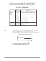
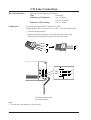
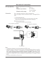
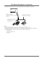
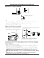
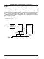
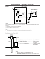
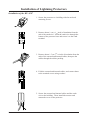
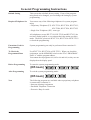
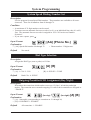
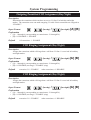
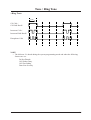
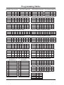
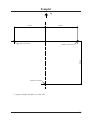
Electronic Modular Switching System
Please read this manual before connecting the
Electronic Modular Switching System.
ELECTRONIC MODULAR SW ITCHING SYSTEM
POWER
MODEL
KX-T206
Thank you for purchasing the Panasonic Model
KX-T206, Electronic Modular Switching System.
System Component
Model No.
Notes
Description
Service
Unit
KX-T206
Electronic Modular Switching System
Telephone
KX-T7130
KX-T7030
KX-T7033
KX-T7020
KX-T7050
KX-T7055
Proprietary telephone with display
Proprietary telephone with display
Proprietary telephone with display
Proprietary telephone
Proprietary telephone
Proprietary telephone
Optional
Equipment
KX-T20691
KX-T30865
DISA/FAX Detect Card
Doorphone
• This Installation Manual does not show complete model numbers that
indicate the country where your models should be used.
The model number of your unit is found on the label affixed to the unit.
MODEL NO.
• A proprietary telephone is abbreviated as “PT”.
• A single line telephone is abbreviated as “SLT”.
2
Precaution
• Keep the unit away from heating appliances and electrical noise generating devices such as
fluorescent lamps, motors and television. These noise sources can interfere with the performance of the Electronic Modular Switching System.
• This unit should be kept free of dust, moisture, high temperature (more than 40˚C/104˚F) and
vibration, and should not be exposed to direct sunlight.
• Never attempt to insert wires, pins, etc. into the vents or other holes of this unit.
• If there is any trouble, disconnect the unit from the telephone line. Plug the telephone directly
to the telephone line. If the telephone operates properly, do not reconnect the unit to the line
until the trouble has been repaired. If the telephone does not operate properly, chances are
that the trouble is in the telephone system, and not in the unit.
• Do not use benzine, thinner, or the like, or any abrasive powder to clean the cabinet. Wipe it
with a soft cloth.
WARNING
WHEN A FAILURE OCCURS WHICH RESULTS IN THE INTERNAL PARTS BECOMING ACCESSIBLE, DISCONNECT THE POWER SUPPLY CORD IMMEDIATELY AND
RETURN THIS UNIT TO YOUR DEALER.
DISCONNECT THE TELECOM CONNECTION BEFORE DISCONNECTING THE
POWER CONNECTION PRIOR TO RELOCATING THE EQUIPMENT, AND RECONNECT THE POWER FIRST.
THIS UNIT IS EQUIPPED WITH AN EARTHING CONTACT PLUG. FOR SAFETY REASONS THIS PLUG MUST ONLY BE CONNECTED TO AN EARTHING CONTACT
SOCKET WHICH HAS BEEN INSTALLED ACCORDING TO REGULATIONS.
THE POWER SOCKET WALL OUTLET SHOULD BE LOCATED NEAR THIS EQUIPMENT AND BE EASILY ACCESSIBLE.
TO PREVENT FIRE OR SHOCK HAZARD, DO NOT EXPOSE THIS PRODUCT TO
RAIN OR ANY TYPE OF MOISTURE.
73/23/EEC
89/336/EEC
92/31/EEC
93/68/EEC
3
Table of Contents
Specifications .......................................................................................................................
Before Installation...............................................................................................................
Unpacking ............................................................................................................................
Name and Location .............................................................................................................
Wall Mounting ....................................................................................................................
Opening Front Cover..........................................................................................................
Frame Ground Connection ................................................................................................
System Connection Diagram .............................................................................................
CO Line Connection ...........................................................................................................
Extension Connection .........................................................................................................
Paralleled Telephone Connection ......................................................................................
Installation of Optional Card and Unit ............................................................................
Installation of Lightning Protectors ..................................................................................
Power Failure Transfer ......................................................................................................
Starting the System .............................................................................................................
General Programming Instructions ..................................................................................
System Programming .........................................................................................................
System Speed Dialing Number Set ....................................................................................
Dial Type Selection ............................................................................................................
Outgoing Permitted CO1 Assignment (Day/Night) ...........................................................
Outgoing Permitted CO2 Assignment (Day/Night) ...........................................................
CO1 Ringing Assignment (Day/Night) ..............................................................................
CO2 Ringing Assignment (Day/Night) ..............................................................................
Doorphone Assignment (Day/Night) .................................................................................
Toll Restriction (TRS) – Class Assignment (Day/Night) ..................................................
TRS Denied Code (CLASS 2, 3) .......................................................................................
TRS Denied Code (CLASS 3) ...........................................................................................
OGM Recording ................................................................................................................
OGM Play ..........................................................................................................................
Fax Connection ..................................................................................................................
CO1 Delayed Ringing Assignment ....................................................................................
CO2 Delayed Ringing Assignment ....................................................................................
Delayed Ringing Count Selection ......................................................................................
Day/Night Switching Mode ...............................................................................................
Day/Night Starting Time ....................................................................................................
System Data Clear .............................................................................................................
Other programs ..................................................................................................................
Tone / Ring Tone .................................................................................................................
Programming Tables...........................................................................................................
Templet ................................................................................................................................
4
5
6
7
7
8
8
8
9
10
11
12
13
14
17
17
18
19
19
19
19
20
20
20
21
21
22
22
22
23
23
24
24
24
25
25
25
26
28
30
33
Specifications
General Descriptions
1. Capacity .................................... CO line
Extension
2
6
2. Control Method ......................... Stored Program CPU: 8 bits CPU
Control ROM: 64 KB, Control RAM: 8 KB
3. Switching Method ..................... Space Division CMOS Crosspoint Switch
4. Power Supplies ......................... Primary
Secondary
Power Failure
AC 110–240 V, 50/60 Hz
Circuit Volt: +5V, +15 V, +30 V
CO 2 assigned to extension 22
5. Dialing ...................................... Outward
Internal
Mode Conversion
Dial Pulse
10 PPS, 20 PPS
Tone Dial
Dial Pulse
10 PPS, 20 PPS
Tone Dial
DP-DTMF, DTMF-DP
6. Connector .................................. CO
Extension
Doorphone
7. EXT Connection ....................... Cable
4-pin connector
4-pin connector
4-pin connector
1 pair wire (single line telephone)
2 pair wire (proprietary telephone)
8. Intercom paths ........................... 2 (including the doorphone path)
Characteristics
1. Station Loop Limit .................... Proprietary telephone
Single line telephone
Doorphone
40 ohms
600 ohms including set
20 ohms
2. Minimum Leak Resistance ....... 15000 ohms
3. Maximum Number of Station
Instruments per line .................. 1 (proprietary telephone) or 3 (single line telephone)
4. Ring Voltage.............................. 90 Vrms at 20 Hz depends on Ringing Load
5. Primary Power .......................... AC 110–240 V, 50/60 Hz, 0.5 A maximum
6. Central Office Loop Limit ........ 1600 ohms maximum
7. Environmental Requirements ... 0–40˚C, 10%–90% (Humidity)
8. Hookswitch Flash
Timing Range ............................ 80 – 1000 msec, 80 – 150 msec
5
Before Installation
Please read the following notes concerning installation and connection before installing the
system.
Safety Installation Instructions
When installing telephone wiring, basic safety precautions should always be followed to reduce the risk
of fire, electric shock and injury to persons, including the following:
1. Never install telephone wiring during a lightning storm.
2. Never install telephone jacks in wet locations unless the jack is specifically designed for wet
locations.
3. Never touch uninsulated telephone wires or terminals unless the telephone line has been
disconnected at the network interface.
4. Use caution when installing or modifying telephone lines.
Installation Precautions
This set is exclusively made for wall mounting only. Avoid installing in the following places. (Doing so
may result in malfunction, noise, or discoloration.)
1. In direct sunlight and hot, cold, or humid places. (Temperature range: 0˚C-40˚C/32˚F-104˚F)
2. Sulfuric gases produced in areas where there are thermal springs, etc. may damage the equipment
or contacts.
3. Places in which shocks or vibrations are frequent or strong.
4. Dusty places, or places where water or oil may come into contact with the unit.
5. Near high-frequency generating devices such as sewing machines or electric welders.
6. On or near computers, telexes, or other office equipment, as well as microwave ovens or air
conditioners. (It is preferable not to install in the same room with the above equipment.)
7. Install at least 1.8 m (6 feet) from radios and televisions. (both the main unit and a proprietary
telephone)
8. Do not obstruct area around the main unit (for reasons of maintenance and inspection – be
especially careful to allow space for cooling above and at the sides of the main unit).
Wiring Precautions
Make sure to keep the following instructions when wiring.
1. Do not wire the telephone cable in parallel with an AC power source, computer, telex, etc. If the
cables are run near those wires, shield the cables with metal tubing or use shielded cables and
ground the shields.
2. If cables are run on the floor, use protectors or the like to protect the wires where they may be
stepped on. Avoid wiring under carpets.
3. Avoid using the same power supply outlet for computers, telexes, and other office equipment.
Otherwise, the KX-T206’s system operation may be interrupted by the induction noise from such
equipment.
4. Please use one pair telephone wire for extension connection of (telephone) equipment such as
standard telephones, answering machines, etc., except proprietary telephones (KX-T7130, KXT7030, KX-T7020, KX-T7033, KX-T7050, KX-T7055, etc.).
5. The AC cord must be plugged off during wiring. After all the wirings are completed, plug the AC
cord into an AC outlet.
6. Mis-wiring may cause the system to operate improperly.
7. If an extension does not operate properly, disconnect the telephone from the extension line and then
connect again, or plug off the AC cord of the system and then on again.
8. The KX-T206 is equipped with a 3-wire grounding type plug. This is a safety feature. If you are
unable to insert the plug into the outlet, contact your electrician to replace your obsolete outlet. Do
not defeat the purpose of the grounding-type plug.
9. Use twisted pair cable for CO line connection.
10. CO lines should be installed with lightning protectors. For details, see pages 14-16.
6
Unpacking
• Main Unit ............................. one
• AC Cord ............................... one
• AC Plug Adaptor .................. one
• Screw and Washer ................ three
• 4-pin Plug ............................. eight
Name and Location
Overview of the Main Unit
AC Inlet
ELECTRONIC MODULAR SW ITCHING SYSTEM
POWER
Power Indicator
Inside View of the Main Unit
Cable Holders
Extension 4-pin Jacks
SYSTEM
EXTN.
5
EXTN.
6
EXTN.
3
EXTN.
4
EXTN.
1
EXTN.
2
CO 2
CO 1
DPH
CO 4-pin Jack
Doorphone Jack
Ground Terminal
GROUND
7
Wall Mounting
1. Place the templet (on page 33) on the wall to
mark the three screw positions.
Templet
2. Install the three screws and washers (included)
into the wall.
3. Hook the main unit on the screw heads.
Opening Front Cover
1. Loosen the screw.
2. Slide the cover in the direction of the
arrow while pressing the marked
position.
ELECTRONIC MODULAR SW I TC HING SYSTEM
POWER
screw
Frame Ground Connection
ELECTRONIC MODULAR SWITCHING SYSTEM
POWER
To ground
IMPORTANT!!!
Connect the frame of the main unit to ground.
8
System Connection Diagram
to CO1 and CO2
2 CO Lines
Doorphone KX-T30865
ELECTRONIC MODULAR SWIT CHING SYSTEM
Panasonic
Doorphone
6 Extensions *
(two pair)
(two pair)
(one pair)
(two pair)
(two pair)
Single Line Telephone
KX-T7050
(two pair)
KX-T7130
(one pair)
(two pair)
Pa
nas
oni
c
O
AUT
KX-T7020
N
SCA
nic
aso
10CH
KX-T7030
Pan
Cordless Phone
KX-T7055
(one pair)
KX-T7033
Telephone Answering
Machine with Facsimile
* One hybrid port and five single-line telephone ports. A hybrid port accepts either a PT or SLT.
9
CO Line Connection
Wire Specification
Connection
The wire specifications are as follows:
Wire
Solid wire
Diameter of conductor
0.4 – 0.65mm
(22, 24, 26 AWG)
Diameter with coating
0.66 – 1.05mm
Use a 4-pin plug (included) to connect CO lines.
A single plug is able to connect two CO lines. Use twisted pair cable.
1. Lift the transparent part.
2. Insert the required telephone wires into the holes of the plug.
Then press the transparent part back into the black part.
T
CO 2
R
CO 2
CO 1
T
CO 1
R
SYSTEM
EXTN.
5
EXTN.
6
EXTN.
3
EXTN.
4
EXTN.
1
EXTN.
2
CO 2
CO 1
DPH
GROUND
To Modular Jacks from
the Central Office
Note
• You can use cable holders to fix the wires.
10
CO 2
CO 1
T
R
T
R
CO 2
CO 1
Extension Connection
Wire Specification
Connection
The wire specifications are as follows:
Wire
Solid wire
Diameter of conductor
0.4 – 0.65mm
(22, 24, 26 AWG)
Diameter with coating
0.66 – 1.05mm
Use a 4-pin plug (included) to connect extension lines.
There are 6 plugs to connect extensions to EXTN. 1 through EXTN. 6
jacks.
1. Lift the transparent part.
2. Insert the required telephone wires into the holes of the plug.
Then press the transparent part back into the black part.
Note:Do not strip the wires.
Insert the wires all the way into the plug.
For a proprietary telephone
For single line telephones
H
T
T
R
R
L
SYSTEM
EXTN.
5
EXTN.
6
EXTN.
3
EXTN.
4
EXTN.
1
EXTN.
2
CO 2
CO 1
DPH
EXTN.
1
H
T
R
L
GROUND
To extensions
Notes
• A proprietary telephone can only be connected to EXTN.1 jack.
• A facsimile must be connected to EXTN.6 jack if an optional DISA/FAX Detect card (KXT20691) is installed. See page 13 to install the card. System programming is also required.
The “#12 Fax Connection” program should be assigned as “ENABLE”. See page 23. The
“#24 Call Incoming Mode Selection” program should be assigned as “DISA”. See page 26.
• The EXTN.1 through EXTN.6 jacks correspond to extension numbers 21 through 26 respectively.
• You can use cable holders to fix the wires.
11
Paralleled Telephone Connection
Any single line telephone can be connected in parallel with a proprietary telephone.
ELECTRONIC MODULAR SW ITCHING SYSTEM
POWER
Modular T-Adaptor
(Panasonic KX-J66 or USOC
RJA2X)
2-conductor wiring cord
Connect pins “T” and “R”.
4-conductor wiring cord
Connect pins “H”, “T”,
“R”, and “L”.
Notes
• The paralleled telephone connection is only available for EXTN.1 jack.
• System programming is required. See “#31 Paralleled Telephone Connection” on page 26.
• The following features are not available for SLT connected in parallel:
Call Splitting
External Feature Access
Conference
12
Installation of Optional Card and Unit
Doorphone (KX-T30865) Connection
T
R
DPH
SYSTEM
EXTN.
5
EXTN.
6
EXTN.
3
EXTN.
4
EXTN.
1
EXTN.
2
CO 2
CO 1
DPH
GROUND
2-conductor wiring cord
Panasonic
KX-T30865
Notes
• The doorphone adaptor is not required for KX-T206.
• To avoid howling, you must assign all extensions as “DISABLE” in the “#06/#76 Doorphone
Assignment (Day/Night)” program when you do not connect a doorphone.
• If howling occurs while using the doorphone feature, check the wiring.
• You can use cable holders to fix the wires.
DISA Card (KX-T20691) Connection
1. Disconnect the AC cord from the system. 3. Attach the DISA card to the marked connectors.
2. Loosen the screws and remove the cover.
EXTN.
6
EXTN.
5
EXTN.
3
SYSTEM
CHING
ULAR SWIT
NIC MOD
ELECTRO
EXTN.
4
EXTN
1
CO2
CO 1
EXTN.
2
DPH
GROUN D
POWER
4. Replace the cover and secure the screws.
5. Connect the AC cord again.
The DISA feature allows an outside caller to have direct access to intercom calls. System programming is required. See “#10 OGM Recording” on page 22 and “#24 Call Incoming Mode
Selection” on page 26.
Keep the following conditions in mind:
• When a caller enters the second digit of an extension number (1 through 6) during the message, he/she can reach the extension directly.
• If the call is not received, the assigned extensions will ring. See “#04/#74 CO1 Ringing
Assignment (Day/Night), “#05/#75 CO2 Ringing Assignment (Day/Night)” on page 20 and
“#60 DISA Ringing Time” on page 28.
• If the caller enters 0, the assigned extensions can receive his/her call. See “#04/#74 CO1
Ringing Assignment (Day/Night), “#05/#75 CO2 Ringing Assignment (Day/Night)” on page
20.
• If the caller enters 7, 8 or 9, or enters nothing, extension 21 will receive his/her call.
• Any calls from a rotary phone will be received by extension 21.
13
Installation of Lightning Protectors
Overview
A lightning protector is a device to be installed on a CO line to prevent a dangerous surge from
entering the building and damaging equipment. A dangerous surge can occur if a telephone line
comes in contact with a power line. Trouble due to lightning surges have been showing a steady
increase with the development of electronic equipment. In many countries, there are regulations
requiring the installation of a lightning protector. A lightning strike to a telephone cable which is
10 m (33 feet) above ground can be as high as 200,000 volts. This system should be installed
with lightning protectors. In addition, grounding (connection to earth ground) is very important
for the protection of the system.
Recommended lightning protector
•
Panasonic KX-A207
Installation
CO
CO
Lightning
Protectors
CO
Main Unit
Terminal
Board
EXTN
SLT
Ground
14
EXTN
EXTN
PT
Ground Connector
Frame
Ground
Installation of Lightning Protectors
Outside
(Main Building)
Protectors
CO
(Another Building)
CO
CO
Terminal
Board
EXTN
EXTN
TEL
Main
Unit
EXTN
SLT
PT
Lightning
Protector
EXTN
TEL
Ground
Notice
If you install an extension outside of the main building, the following precautions are recommended:
(1) Install the extension wire underground.
(2) Use a conduit to protect the wire.
Note
• The lightning protector for an extension is different from that for CO.
Installation of an Earth Rod
Lightning
Protector
CO
(1)
(2)
(3)
(4)
Grounding
Wire
Main
Unit
Installation location of the earth rod ...... Near the protector
Check obstructions ................................ None
Composition of the earth rod ................. Metal
Depth of the earth rod ............................ More than 50 cm
(20 inches)
(5) Size of the grounding wire .................... Thickness is greater
than 16 AWG
(Underground)
Earth Rod
Notes
• The above figures are recommendations only.
• The length of earth rod and the required depth depend on the
composition of the soil.
15
Installation of Lightning Protectors
Installation of the KX-A207
1. Secure the protector to a building with the enclosed
mounting screws.
2. Remove about 1 cm (13/32 inch) of insulation from the
end of the earth wire. Insert the earth wire through the
bottom of the protector base and secure it to the earth
terminal.
3. Remove about 1.5 cm (19/32 inch) of insulation from the
ends of the external and internal cables, then pass the
cables through the rubber packing.
4. Fold the external and internal cables, and connect them
to the terminal screws using washers.
5. Secure the external and internal cables and the earth
wire to the building. Then, install the arrester and
mount the cover on the protector.
16
Power Failure Transfer
In the event of a power failure, CO2 is connected to extension 22 automatically.
Note
• The system programmed data is protected by the factory provided lithium battery.
Starting the System
Plug the AC power cord into the system and an AC outlet.
• The power indicator of the system will light.
Note
• The plug adaptor is to be used if the power plug will not fit your socket. Assemble as shown
in the illustration, using the plug which fits your socket. In this case, be sure to connect the
frame of the unit to ground because the ground line in the power cable cannot be used.
to power outlet
power plug
plug adaptor
17
General Programming Instructions
Default Setting
This system has a default factory setting. If any of the programming needs to be changed, you can change the setting by system
programming.
Required Telephone Set
You can use any of the following telephones for system programming:
• Proprietary Telephone (PT): KX-T7130, KX-T7030, KX-T7033,
KX-T7020, KX-T7050, KX-T7055
• Single Line Telephone (SLT): tone type
All telephones (except KX-T7130, KX-T7030 and KX-T7033) do
not have display panels, so you cannot check the setting you have
made. Therefore, please use KX-T7130, KX-T7030 or KX-T7033
to check the programming.
Extensions Used for
Programming
System programming can only be performed from extension 21.
To Check the
Programmed Data
Use KX-T7130, KX-T7030 or KX-T7033. When you check the
assignment, set the MEMORY switch on the PT to “PROGRAM”.
Enter “#” and the program address.
You cannot check programs #60, #62 to 66 and #68, as they are not
displayed on the display panel.
Before Programming
To enter the system programming mode:
[Off-hook] 6
After Programming
18
0
6
2
0
6
To exit the system programming mode:
[Off-hook] 6
Note
2
2
0
6
The following programs are available when a proprietary telephone
is connected to extension 21:
• Intercom Alerting Assignment
• Paralleled Telephone Connection
• Executive Busy Override
System Programming
System Speed Dialing Number Set
Description
Used to program System Speed Dial numbers. These numbers are available to all extension users. There are 80 numbers from 00 through 79.
Condition
• A maximum of 32 digit numbers can be stored.
• You must store an automatic line access code (0 or 9), or an individual line code (81 or 82)
first. The automatic line access code is assigned in “#52 CO Line Access Number
Selection”.
• If you store a pause, press .
Input Format
0
0
[AA] [Phone No.]
Explanation
• [AA]=Speed dial number: 00 through 79
Default
• Phone number: 32 digits max.
Not stored
Dial Type Selection
Description
Assigns the Dial Type (tone or pulse) to CO line.
Input Format
0
1
[A] [B]
Explanation
• [A]= 1: CO1/ 2: CO2
Default
•
[B]= 0: PULSE/ 1: TONE
Both COs– 0: PULSE
Outgoing Permitted CO1 Assignment (Day/Night)
Description
Determines the extensions which can have access to CO line 1 in both day and night
modes. The extension users can make outgoing CO calls if their extensions are assigned as
“ENABLE”.
Input Format
0
2
(for day)
/ 7 2
(for night)
[A] [B]
Explanation
• [A]= 1 through 6 (corresponding to extension no. 21 through 26)
• [B]= 0: DISABLE/ 1: ENABLE
Default
All extensions– 1: ENABLE
19
System Programming
Outgoing Permitted CO2 Assignment (Day/Night)
Description
Determines the extensions which can have access to CO line 2 in both day and night
modes. The extension users can make outgoing CO calls if their extensions are assigned as
“ENABLE”.
Input Format
0
3
(for day)
/ 7 3
(for night)
[A] [B]
Explanation
• [A]= 1 through 6 (corresponding to extension no. 21 through 26)
• [B]= 0: DISABLE/ 1: ENABLE
Default
All extensions– 1: ENABLE
CO1 Ringing Assignment (Day/Night)
Description
Assigns the extensions which will ring when a call from CO line 1 is received in both day
and night modes.
Input Format
0
4
(for day)
/ 7 4
(for night)
[A] [B]
Explanation
• [A]= 1 through 6 (corresponding to extension no. 21 through 26)
• [B]= 0: DISABLE (not ring)/ 1: ENABLE (ring)
Default
extension 21–1: ENABLE
other extensions– 0: DISABLE
CO2 Ringing Assignment (Day/Night)
Description
Assigns the extensions which will ring when a call from CO line 2 is received in both day
and night modes.
Input Format
0
5
(for day)
/ 7 5
(for night)
Explanation
• [A]= 1 through 6 (corresponding to extension no. 21 through 26)
• [B]= 0: DISABLE (not ring)/ 1: ENABLE (ring)
Default
20
extension 21–1: ENABLE
other extensions– 0: DISABLE
[A] [B]
System Programming
Doorphone Assignment (Day/Night)
Description
Assigns the extensions which will ring when a doorphone call is received and enables to
call the doorphone in both day and night modes.
Condition
• All extensions must be assigned as “0: DISABLE”, if you do not connect a doorphone to
the system.
Input Format
0
6
(for day)
/ 7 6
(for night)
[A] [B]
Explanation
• [A]= 1 through 6 (corresponding to extension no. 21 through 26)
• [B]= 0: DISABLE/ 1: ENABLE
Default
All extensions– 1: ENABLE
Toll Restriction (TRS) – Class Assignment (Day/Night)
Description
Assigns a Toll Restriction Class to each extension in both day and night modes. The Toll
Restriction feature can prohibit certain extension users from placing unauthorized toll calls.
The following four classes are available:
Class
Restricted calls
CLASS 1 None
CLASS 2 Numbers programmed in “#08 Denied code (Class 2, 3) ”
CLASS 3 Numbers programmed in “#08 Denied code (Class 2, 3)
and “#09 Denied code (Class 3)”
CLASS 4 All CO calls
Input Format
0
7
(for day)
/ 7 7
(for night)
[A] [B]
Explanation
• [A]= 1 through 6 (corresponding to extension no. 21 through 26)
• [B]= 1: CLASS 1/ 2: CLASS 2/ 3: CLASS 3/ 4: CLASS 4
Default
All extensions– 1: CLASS 1
21
System Programming
TRS Denied Code (CLASS 2, 3)
Description
Allows you to specify the numbers which are toll-restricted for TRS Class 2 and Class 3.
Condition
• The character “ ” can be any number.
Input Format
0
8
Explanation
• [A]= Code No.: 0 through 9 1 digit
Default
[A] [Denied code No.]
• Denied code number: 7 digits,
All codes– Not stored
TRS Denied Code (CLASS 3)
Description
Allows you to specify the numbers which are toll-restricted for TRS Class 3.
Condition
• The character “ ” can be any number.
Input Format
0
9
[A] [Denied code No.]
Explanation
• [A]= Code No.: 0 through 9 1 digit
Default
• Denied code number: 7 digits,
All codes– Not stored
OGM Recording
Description
Used to record an outgoing message for Direct Inward System Access (DISA).
Condition
• The recording time is a maximum of 16 seconds.
• If you perform programming with a PT, the message “RECORDING” will be displayed on
its panel.
• If the DISA/FAX Detect card is not installed, you will hear a reorder tone and the program
is finished.
Message example: “This is AAA company. Please enter 1 for Mr. AA, 2 for Mr. BB .......
6 for Ms. FF. Thank you.”
Input Format
22
1
0
(Record your message)
System Programming
OGM Play
Description
Confirms the outgoing message recorded in the OGM Recording program.
Condition
• If you perform programming with a PT, the message “PLAYBACK” will be displayed on
its panel.
Input Format
1
1
Fax Connection
Description
Allows the system to detect the CNG tone from a facsimile. If it is set to “ENABLE”,
extension 26 will receive fax transmission data.
Condition
• The optional DISA/FAX Detect card (KX-T20691) should be installed.
• The “#24 Call Incoming Mode Selection” program should be assigned as “DISA”.
• Extension 26 should be assigned as “DISABLE” in the “#04/#74 CO1 Ringing Assignment
(Day/Night)”, “#05/#75 CO2 Ringing Assignment (Day/Night)” and “#06/#76 Doorphone
Assignment (Day/Night)” programs.
Input Format
1
2
[A]
Explanation
• [A]= 0: DISABLE (not detect)/ 1: ENABLE (detect)
Default
0: DISABLE
23
System Programming
CO1 Delayed Ringing Assignment
Description
Assigns delayed ringing to extensions when a call from CO line 1 is received.
Condition
• The number of delayed rings is assigned by the “#15 Delayed Ringing Count Selection”
program.
• This feature is not available for the calls sent by the DISA feature.
Input Format
1
3
[A] [B]
Explanation
• [A]= 1 through 6 (corresponding to extension no. 21 through 26)
• [B]= 0: DISABLE (not delayed)/ 1: ENABLE (delayed)
Default All extensions– 0: DISABLE
CO2 Delayed Ringing Assignment
Description
Assigns delayed ringing to extensions when a call from CO line 2 is received.
Condition
• The number of delayed rings is assigned by the “#15 Delayed Ringing Count Selection”
program.
• This feature is not available for the calls sent by the DISA feature.
Input Format
1
4
[A] [B]
Explanation
• [A]= 1 through 6 (corresponding to extension no. 21 through 26)
• [B]= 0: DISABLE (not delayed)/ 1: ENABLE (delayed)
Default All extensions– 0: DISABLE
Delayed Ringing Count Selection
Description
Assigns the number of delayed rings that will be sent to the assigned extensions from the
CO lines.
Input Format
1
5
[A]
Explanation
• [A]= 1: After 1 ring/ 2: After 2 rings/ 3: After 3 rings/ 4: After 4 rings
Default
24
2: After 2 rings
System Programming
Day/Night Switching Mode
Description
Assigns automatic or manual day/night mode.
Condition
• If automatic switching mode is assigned, day/night mode is switched at the time
programmed in “#71 Day/Night Starting Time”.
Input Format
7
0
[A]
Explanation
• [A]= 0: Manual/ 1: Automatic
Default
0: Manual
Day/Night Starting Time
Description
Sets the starting time when automatic day/night mode is programmed in the “#70 Day/
Night Switching Mode” program.
Input Format
7
1
[A] [BB] [CC] [D]
Explanation
• [A]= 1: Day start time / 2: Night start time
• [CC]=Minute: 00-59
Default
Day– 9:00 AM
• [BB]= Hour: 01-12
• [D]=0: AM / 1: PM
Night–5:00 PM
System Data Clear
Description
Allows the system to re-initialize the system-programmed data. The features mentioned in
“Station Feature Clear” are also re-initialized. See page 11 of the User Manual. When all
the programmed data is cleared, the system will restart with the default setting.
Input Format
9
9
25
System Programming
Other Programs
• Call Blocking Mode Setting
Assigns whether or not to prevent the DTMF
signal from being sent to a CO line. This feature
is useful when a Central Office in your country
accepts both tone and pulse signals or when you
have access to your host PBX with a pulse dial.
Input Format: #20 [A]
• [A]=0: DISABLE (default)/ 1: ENABLE
• Host PBX Access Code Assignment
Assigns a Host PBX access code to make an
outside call, if the system is installed behind the
host PBX. A pause is automatically inserted
after the access code and the toll restriction
feature applies to the number after the code.
Input Format: #21 [A] [code] #
• [A]=1: CO1/ 2: CO2
• [code] = 2 digits max. (Default : Not stored)
• Hookswitch Flash Time Assignment
Sets the time to send the flash signal to each CO
line.
Input Format: #22 [A] [B]
• [A]=1: CO1/ 2: CO2
• [B]=0: 80 ms/ 1: 100 ms / 2: 160 ms/ 3: 300 ms/
4: 600 ms (default) / 5: 900 ms /
6: 1200 ms
• CO Pulse Selection
Assigns to send the pulse to CO line during a
conversation with an outside party when the “#01
Dial Type Selection” program is assigned as
“Pulse”.
Input Format: #23 [A]
• [A]=0: DISABLE/ 1: ENABLE (default)
• Call Incoming Mode Selection
Assigns whether to use the DISA feature or not.
This program is available when the DISA/FAX
Detect card is installed.
Input Format: #24 [A] [B]
• [A]=1: CO1/ 2: CO2
• [B]=0: NORMAL/ 1: DISA (default)
• Paralleled Telephone Connection
Assigns whether extension 21 will be connected
in parallel with a single line telephone or not.
Input Format: #31 [A] [B]
• [A]=1 (extension 21)
• [B]=0: DISABLE (default)/ 1: ENABLE
• Executive Busy Override
Determines whether extension 21 performs the
Executive Busy Override feature.
Input Format: #32 [A] [B]
• [A]=1 (extension 21)
• [B]=0: DISABLE (default)/ 1: ENABLE
• Tone Waiting Time After OGM
Sets the time between sending an outgoing
message and sending the ringback tone.
Input Format: #40 [A]
• [A]=0: 0 SEC/ 1: 5 SEC (default)/ 2: 10 SEC/
3: 15 SEC
• Hold Recall Time
Assigns the length of the hold recall timer and
transfer recall timer. The hold recall timer is
used to alert an extension that a call has been
held for an extended period of time. The
transfer recall timer is used to alert an extension
that a transferred call has not been answered for
an extended period of time.
Input Format: #50 [A]
• [A]=0: 30 SEC (default)/ 1: 1 MIN / 2: 2 MIN/
3: 3 MIN/ 4: 4 MIN/ 5: DISABLE
• Hold Mode Selection for SLT
Assigns the method to put a call on hold with
SLTs.
Input Format: #51 [A]
• [A]=1: MODE 1 (hooking) (default)
2: MODE 2 (hooking and dial 6)
• CO Line Access Number Selection
Selects the automatic line access number.
Input Format: #52 [A]
• [A]=1: 9/ 2: 0 (default)
• Bell Off Detection
Sets the time between one bell signal detection
and the next signal from a Central Office.
Input Format: #25 [A]
• [A]=1: 6 SEC (default)/ 2: 12 SEC
• Intercom Alerting Assignment
Assigns the intercom alerting mode to extension
21 when an intercom call reaches extension 21.
Input Format: #30 [A] [B]
• [A]=1 (extension 21)
• [B]=0: TONE (default)/ 1: VOICE
26
• Conference Tone
Assigns whether or not to delete the conference
tone. You hear the tone when the conference or
the executive busy override feature begins and
finishes.
Input Format: #53 [A]
• [A]=0: DISABLE/ 1: ENABLE (default)
System Programming
Other Programs (continued)
• DISA Ringing Time Assignment
Sets the time to forward a call sent by the DISA
feature to other extensions. If the call is not
answered by the designated extension within the
programmed time, the call is forwarded to
extensions which are not assigned as “DISABLE” in the #04/#74 CO1 Ringing Assignment
(Day/Night) and #05/#75 CO2 Ringing Assignment (Day/Night). If “DISABLE” is selected in
this program, the telephone at the designated
extension rings for 60 seconds and the call is not
forwarded.
Input Format: #60 [A]
• [A]=0: DISABLE / 1: 10 SEC/
2: 20 SEC (default)/ 3: 35 SEC
• Toll Restriction Code Check
• Hookswitch Flash Time Range
Assignment
Sets the hookswitch flash time range.
Input Format: #65 [A]
• [A]=1: 80–1000ms (default)/ 2: 80–150ms
• Dial Start Time
Sets the time the system waits before dialing
after a CO lined is seized.
Input Format: #66 [A]
• [A]=1: 800 ms (default)/ 2: 2000 ms
• Pulse Speed Selection
Sets the pulse speed for CO lines.
Input Format: #68 [A]
• [A]=1: 10 PPS (default)/ 2: 20 PPS
Assigns whether “ ” or “#” is to be checked or
not when a user dials them in the Toll Restriction
code.
Input Format: #62 [A]
• [A]=0: DISABLE/ 1: ENABLE (default)
• CO Indicator Assignment
Assigns whether an incoming CO call indicates
or not on the CO button. Also it allows an
extension user to answer the call by pressing the
CO button when “DISABLE” is selected in the
#04/#74 “CO1 Ringing Assignment” or the #05/
#75 “CO2 Ringing Assignment” program.
Input Format: #63 [A]
• [A]=0: DISABLE (The indicator lights red and
a user cannot answer the
call.)
1: ENABLE (The indicator is flashing and
a user can answer the call.)
(default)
• Pulse Break Ratio Assignment
Assigns the pulse break ratio during dial pulsing.
Input Format: #64 [A]
• [A]=1: 66% (default)/ 2: 60%
Note
• You cannot check the assignments of the above programs by setting the MEMORY switch to
“PROGRAM”, and entering “#” and the program address.
27
Tone / Ring Tone
<Tone>
1 sec
Confirmation Tone 1
Confirmation Tone 2
Confirmation Tone 3
(Conference Tone)
Dial Tone 1
Dial Tone 2
Busy Tone
Reorder Tone
Ringback Tone
Do Not Disturb (DND)
Tone
15 sec
Hold Alarm
Call Waiting Tone
28
Tone / Ring Tone
<Ring Tone>
1 sec
CO Calls /
CO Hold Recall
Intercom Calls /
Intercom Hold Recall
Doorphone Calls
NOTE
• The dial tone 2 is heard during the system programming mode and when the following
features are set:
Do Not Disturb
Call Pickup Deny
Call Forwarding
Data Line Security
29
Programming Tables
[#00] System Speed Dialing Number Set
No.
00
01
02
03
04
05
06
07
08
09
10
11
12
13
14
15
16
17
18
19
20
21
22
23
24
25
26
27
28
29
30
31
32
33
34
35
36
37
38
39
30
Name
Phone No. (32 digits max.)
Programming Tables
No.
40
41
42
43
44
45
46
47
48
49
50
51
52
53
54
55
56
57
58
59
60
61
Name
Phone No. (32 digits max.)
62
63
64
65
66
67
68
69
70
71
72
73
74
75
76
77
78
79
31
Programming Tables
[#01] Dial Type Selection
[#12] Fax Connection
Default CO1 CO2
0: PULSE
1: TONE
✓
[#70] Day/Night Switching Mode [#71] Day/Night Starting Time
Default Selection
0: DISABLE
1: ENABLE
✓
[#02] Outgoing Permitted CO 1 Assignment (Day)
Default Selection
[#03] Outgoing Permitted CO 2 Assignment (Day)
Default Ext.21 Ext.22 Ext.23 Ext.24 Ext.25 Ext.26
0: DISABLE
1: ENABLE
✓
[#04] CO 1 Ringing Assignment (Day)
✓
Default Ext.21 Default Ext.22 Ext.23 Ext.24 Ext.25 Ext.26
0: DISABLE
1: ENABLE
✓
[#05] CO 2 Ringing Assignment (Day)
✓
[#06] Doorphone Assignment (Day)
[#07] Toll Restriction (TRS) – Class Assignment (Day)
✓
✓
[#77] Toll Restriction (TRS) – Class Assignment (Night)
Default Ext.21 Ext.22 Ext.23 Ext.24 Ext.25 Ext.26
1: CLASS 1
2: CLASS 2
3: CLASS 3
4: CLASS 4
✓
Default Ext.21 Ext.22 Ext.23 Ext.24 Ext.25 Ext.26
0: DISABLE
1: ENABLE
✓
✓
[#76] Doorphone Assignment (Night)
Default Ext.21 Ext.22 Ext.23 Ext.24 Ext.25 Ext.26
0: DISABLE
1: ENABLE
✓
Default Ext.21 Default Ext.22 Ext.23 Ext.24 Ext.25 Ext.26
0: DISABLE
1: ENABLE
✓
✓
[#75] CO 2 Ringing Assignment (Night)
Default Ext.21 Default Ext.22 Ext.23 Ext.24 Ext.25 Ext.26
0: DISABLE
1: ENABLE
✓
[#74] CO 1 Ringing Assignment (Night)
Default Ext.21 Default Ext.22 Ext.23 Ext.24 Ext.25 Ext.26
0: DISABLE
1: ENABLE
✓
[#73] Outgoing Permitted CO 2 Assignment (Night)
Default Ext.21 Ext.22 Ext.23 Ext.24 Ext.25 Ext.26
0: DISABLE
1: ENABLE
Default Selection
9:00AM
5:00PM
Default Ext.21 Ext.22 Ext.23 Ext.24 Ext.25 Ext.26
0: DISABLE
1: ENABLE
✓
1: DAY
2: NIGHT
[#72] Outgoing Permitted CO 1 Assignment (Night)
Default Ext.21 Ext.22 Ext.23 Ext.24 Ext.25 Ext.26
0: DISABLE
1: ENABLE
✓
0: MANUAL
1: AUTO
Default Ext.21 Ext.22 Ext.23 Ext.24 Ext.25 Ext.26
1: CLASS 1
2: CLASS 2
3: CLASS 3
4: CLASS 4
✓
[#08] TRS Denied Code [#09] TRS Denied Code
(CLASS 2, 3)
(CLASS 3)
[#13] CO 1 Delayed Ringing Assignment
Code Number (7 digits)
0
1
2
3
4
5
6
7
8
9
0: DISABLE
1: ENABLE
32
Code Number (7 digits)
0
1
2
3
4
5
6
7
8
9
Default Ext.21 Ext.22 Ext.23 Ext.24 Ext.25 Ext.26
✓
[#14] CO 2 Delayed Ringing Assignment
Default Ext.21 Ext.22 Ext.23 Ext.24 Ext.25 Ext.26
0: DISABLE
1: ENABLE
✓
[#15] Delayed Ringing Count Selection
Default Selection
1: 1 RING
2: 2 RINGS
3: 3 RINGS
4: 4 RINGS
✓
Templet
Up
71 mm
Install a screw here
77 mm
106 mm
Install a screw here
Install a screw here
• Copy the templet and place it on the wall.
33
When you ship the product
Carefully pack and send it prepaid, adequately and preferably in the original carton. Attach a
postage-paid letter, detailing the symptom, to the outside of the carton. DO NOT send the product to the Executive or Regional Sales offices. They are NOT equipped to make repairs.
Product service
Panasonic Servicenters for this product are listed in the servicenter directory. Consult your
authorized Panasonic dealer for detailed instructions.
The serial number of this product may be found on the label affixed to the bottom of the unit.
You should note the serial number of this unit in the space provided and retain this book as a
permanent record of your purchase to aid in identification in the event of theft.
MODEL NO.:
KX-T206
SERIAL NO.:
For future reference
DATE OF PURCHASE
NAME OF DEALER
DEALER’S ADDRESS
Matsushita Electric Industrial Co., Ltd.
Central P.O. Box 288, Osaka 530-91, Japan
Printed in Japan
PQQX11318XA KW0495M5066