1
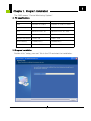
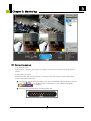
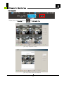
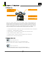
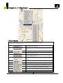
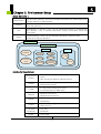
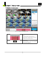
CMS
User's Manual
0
Contents
Contents
Chapter 1. Program Installation
1.1 PC specifications
1.2 Program Installation
2
2
Chapter 2. For the start of CMS
3
2.1 Site Registration Setup (Network Camera Registration)
2.2 Group Registration Setting
5
9
Chapter 3. Monitoring
3.1
3.2
3.3
3.4
3.5
3.6
13
15
15
16
17
18
Connecting camera
Information Tap
Recording Tap
PTZ Tap
Color Tap
Snapshot
Chapter 4. E-Map Mode
4.1
4.2
4.3
4.4
20
Camera Icon
Sensor / Alarm Icon
Local / Site / Group E-Map
E-Map Pop-up Menu
22
22
23
23
Chapter 5. Environment Setup
5.1 System Setup
5.2 User Setting
5.3 Plug-in Setting
25
26
28
Chapter 6. Search Mode
6.1 Serch
6.2 Log view
6.3 Bookmark
29
32
34
Chapter 7. Backup Mode
35
36
38
7.1 Selection of backup scope
7.2 Inf / AVI Backup
7.3 How to view Inf backup file
1
1
Chapter 1. Program Installation
The CMS means "Central Monitoring System".
1.1 PC specifications
Minimum Specifications
Recommended Specifications
CPU
Pentium IV 2.0GHz
Pentium IV 3.0GHz or More
Main Memory
128MB
512MB or More
O/S
Windows 2000, XP
Windows 2000, XP, Vista
Web Browser
I.E 6.0
I.E 6.0
Monitor Resolution
1024 x 768
1280 x 1024
Video Memory
128MB(16CH)
256MB(64CH)
Network
10 Base-T Ethernet
100 Base-T Ethernet
1.2 Program Installation
Double click "setup_cms.exe" file in the CD and start the installation.
2
2
Chapter 2. For the start of CMS
Start the program by click of CMS icon on the desktop.
The below window appears afterwards.
[Pic 2-1] Monitoring Screen
[ Button explain ]
Full screen view
Max. view
Screen minimize
Login button
Login ID
(
)
(
)
Site registration
selection
Group registration
selection
Site registration
(Network camera
registration)
Group registration
3
2
Chapter 2. For the start of CMS
PC speaker volume control
No sound
PC HDD Info
CMS termination
Information
Storage function setting
PTZ setting (At present Zoom
function available only)
Color setting
Setup
Recorded file search
E-Map
Refresh
back to initial screen
screen division (4 to 64 channel)
Date and time synchronized with
PC
Network Hologram
In network connected,
the hologram will shine.
<Login>
All functions can be performed
only after login. In the setup
menu, the operators can be
created or added. The function
may be limited by authorized
ID and Password.
Ref : Factory default ID and
password are admin / admin.
Mind the letter in capital or
minuscule when typing in the
ID and Password.
[Pic 2-2] Login window
4
2
Chapter 2. For the start of CMS
2.1 Site Registration Setup (Network Camera Registration)
By right-click, pop-up menu appears. Choose “Add
Site” menu. Then site Information window appears.
[Pic 2-3] Pop-up menu site addition
[Pic 2-4] Site information window
[ Button explain ]
Site address
Virtual keyboard
`
IP Address
Port number
# of channel setting in a site
(If 2 channels are selected,
one codec is MPEG4 and
the other one is MJPEG. The
codec may be change.
5
2
Chapter 2. For the start of CMS
Web port number
Types of site
(At present IP
only)
Camera
Type in ID
Type in Password
Site name
(If you leave it blank, IP
address will be shown.
Environmental setup of sites
Refer “Pic 2-6”
Save and Exit
Exit without save
[Virtual Keyboard]
[Pic 2-5] Virtual keyboard
6
Chapter 2. For the start of CMS
[Pic 2-6] Environment setup
Site channel selection
Codec selection
MPEG4 and MJPEG only possible
If you select MPEG4 at Cam1, the other channel
codec will be MJPEG.
Sensor setting
Alarm output setting
7
2
2
Chapter 2. For the start of CMS
[Site address pop-up menu]
1.
<Root>
By right-click onto “SITE”, menu appears.
Disconnect all sites
Site adding
Local E-Map can be shared
with users. Under the local
E-Map, it is inactive.
2.
<Site>
By right-click onto the registered site, the menu
appears
Connect site
Disconnect site
Site editing
Can not change IP address
and port number
Site deletion
When camera is
disconnected, it is activated.
3.
<CAMERA>
By right-click onto the registered site channel, menu
appears
Site camera connection
Disconnection
[Ref]
In case of 1 channel in one site, you may have 64 sites.
'Load Site E-map' open the unique 16 E-maps of sites. It can connect a camera, sensor, and alarm existing
within the side.
[Notice]
The actual sensor number can be shown in a event happening.
The actual alarm number can be shown in a event happening.
In regardless of the selected sensor and alarm in “Pic 2-6 Network Camera Environment Setup”,
the actual number of sensor and alarm indicate the event occurring.
8
Chapter 2. For the start of CMS
2.2 Group Registration Setting
Click
<GROUP>. Right-click onto the
<Group>, you may select <Add Group> .
Then <Group information> window appears.
[Pic 2-7] Add group pop-up menu
[Pic 2-8] Group addition
9
2
2
Chapter 2. For the start of CMS
Select camera channel
Type in group name
Type in the description of the
group selected
Registered site
( See site registration)
Adding the selected site to the
group
Camera Channel Deletion
Site Deletion
Save above settings and close
Cancel the settings and close
[Reference]
You may register 64 cameras in a group.
<How to register group>
Drag & drop the site and camera onto a group you wish to add. Or you may use “Add”
button.
<How to delete group>
Drag & drop the site and camera onto site address.
Or you can use “Del” button or “Del Site”.
10
2
Chapter 2. For the start of CMS
[Group address pop-up menu]
1.
<Root>
Right-click on to “Group”, the menu appears
All groups disconnection
Group addition
Save the connected
display in different group
name
Local E-Map can be
shared with users. Under
the local E-Map condition,
it is inactive.
2.
<Group>
Right-click on to sub-group like <Group1>, the menu
appears
Group connection
Group disconnection
Group edition
Group deletion
When camera is
disconnected, it is activated.
3.
<Site>
Right-click onto the registered site and channel,
menu appears
Site camera connection
Disconnection
11
Chapter 2. For the start of CMS
[Reference]
Group E-map open : You can open your own unique 16 E-Maps per group. In this
case, you can connect the cameras and sensors and alarms existing within the group.
[Notice]
The number of sensor # is shown in the event by sensor detection.
The number of alarm is shown in the event by alarm output.
There are 3 types of E-map.
1. Local E-map
Max. 64 channels can be stored. In regardless of sites and groups, 64
channels can be shown. One camera may have a specified sensor or alarm.
2. Group E-map
Max. 64 channels can be stored. It shows the specified group only. One camera
may have a specified sensor or alarm.
3. Site E-map
It is 1-2 channel E-Map. It is only for a registered unique site. It shows a
camera with its own sensors and alarms.
12
2
3
Chapter 3. Monitoring
[Pic 3-1] Picture of Monitoring screen
3.1 Connecting camera
1. By Drag & Drop
Using mouse, drag the site, group or camera from the site section and drop them to
screen.
2. Using Pop-up menu
Clicking mouse right on site, group or camera in the site section, using connecting
menu among pop-up menu.
Connecting site showing as yellow icon and connecting camera showing as red
icon. “
” is showing basic information of site, network hologram
is starting.
Below picture showing that connecting the site.
13
3
Chapter 3. Monitoring
[Pop-up menu on the monitoring screen]
<Group>
Showing the menu when clicking right button of
mouse
Disconnecting the channel
Disconnecting the site
Continuous recording
Motion recording
Sensor recording
Searching the local data
PTZ, alarm control
Refer “PTZ Tap”
Color setting
Refer “Color Tap”
Link to administrators
page of remote site
<Display Icon>
If the site is connected below event icons are showing.
Each event icon means below.
Continuous recording
Motion setting and motion event
Motion event
Sensor setting and sensor event
Sensor event
Alarm event
14
3
Chapter 3. Monitoring
3.2 Information Tap
[Pic 3-2] Information Tap
Continuous recording setting
Motion recording setting
Sensor recording setting
Snapshot function
Print or save current screen to
BMP/JPG file.
( see chapter “SNAPSHOT” )
You have to setting the save folder for saving. See chapter “Setting”
3.3 Recording Tap
[Pic 3-3] Recording tap
Select channel to save
Showing previous 16 channels
Continuous
Recording
Motion
Recording
Sensor
Recording
Select all current 16 channels
If they already selected, cancel
all channel.
(It is valid only network
connected channel)
Showing next 16 channels
15
3
Chapter 3. Monitoring
3.4 PTZ Tap
[Pic 3-4] PTZ Tap
[Preset Function]
Dial button/ Preset number
Delete all preset
Preset setting
Move to preset
[PTZ Function]
Pan, Tilt, Zoom and Focus
setting
Auto Pan setting
Example) <Preset 10 Setting >
Move the PTZ camera and push the dial button (
Preset setting (
)
) and push the
After press dial button (
), press Preset move button (
Camera goes to the preset point
[Notice] This function is only valid with PTZ camera
16
).
3
Chapter 3. Monitoring
3.5 Color Tap
[Pic 3-5] Color Tap
Brightness setting
Contrast setting
Saturation setting
Hue setting
Setting each function
(Brightness, Contrast, Saturation,
Hue)
17
3
Chapter 3. Monitoring
3.6 Snapshot
Below picture is Snapshot button(
)of Information Tap
[Pic 3-6] Snapshot screen
[Pic 3-7] Print screen of snapshot
18
3
Chapter 3. Monitoring
[Snapshot button]
Preview
Saving
Print
Refresh
Mirroring
Flip
Negative image
Brightness control bar
Contrast control bar
Exit
19
4
Chapter 4. E-Map Mode
E-Map screen
Monitoring
screen
[Pic 4-1] E-Map mode screen
[ Button explain ]
E-Map full screen view
E-Map max. view
E-Map minimize
Log-in ID
Select SITE add
Select GROUP add
SITE add (Network camera add)
GROUP add
TIME display
Network Hologram
(Working once a SITE connected)
EXIT E-MAP
Previous, Next Map view
20
4
Chapter 4. E-Map Mode
Open E-Map folder
(Can add other E-Map file)
Registered E-Map
Select E-Map by mouse click
(Max. 16 E-Map can be added)
Alarm ON/OFF
Sensor display
Standard camera icon
Spread camera icon
Like below picture, E-Map screen and monitoring screen can be cross change by
double clicking. In mini E-Map screen, red dot is camera, yellow is sensor and green is
alarm. Location change is also possible in mini E-Map.
Mini E-Map
[Pic 4-2] Screen change between E-Map and Monitoring screen
21
4
Chapter 4. E-Map Mode
4.1 Camera Icon
1. Counterclockwise
rotation
4. LED
2. Channel No.
3. Camera selection
5. Clockwise rotation
6. Preview screen
[Pic 4-3] Camera Icon
There are 4 types camera icon as like standard, spread, preview-standard and
preview-spread. Click the right button in mouse. Then there is a Spread Mode which
changes camera icon from standard camera icon into spread camera icon. There are
2 ways to use preview screen. One is choosing preview in pop-up menu and the
other is double-clicking. All preview screen would be appear or disappear once
clicking the E-Map one more time which already displaying in E-Map screen.
1. Counterclockwise rotation : Rotate the camera counterclockwise (Total 12 directions) .
2. Channel No. : Channel number of camera.
3. Camera selection : Show the channel in E-Map mode monitoring screen.
4. LED : Connection status / Motion / Sensor.
5. Clockwise rotation : Rotate the camera clockwise (Total 12 directions)
6. Preview screen : Show the camera picture.
4.2 Sensor / Alarm Icon
[Pic 4-4] Sensor icon
Choose the sensor which is set in “Pic 2-6 Environment setup”
[Reference] Real sensor number is displayed in SITE E-Map mode.
[Pic 4-5] Alarm icon
Choose the alarm which is set in “Pic 2-6 Environment setup”
[Reference] Real alarm number is displayed in SITE E-Map mode.
22
4
Chapter 4. E-Map Mode
4.3 Local / Site / Group E-Map
There are 3 kinds of E-Map independently, Site E-Map, Group E-Map, Local E-Map.
Camera, Sensor, Alarm which connected in one site can be located in Site E-Map. And
real sensor / alarm no. are displayed during sensor / alarm event.
Camera, Sensor, Alarm which listed site in group can be located in Group E-Map.
And the designated sensor / alarm in “Pic 2-6 Network Camera Environment Setup” are
displayed accordingly.
All Camera, Sensor, Alarm can be located in Local E-Map.
And the designated sensor / alarm in “Pic 2-6 Network Camera Environment Setup” are
displayed accordingly.
4.4 E-Map Pop-up Menu
Listed menu when mouse right button is clicked
in E-Map screen (supported in E-Map mode)
Place Camera XX
Place XX channel
camera
Place Sensor XX
Place XX channel
sensor
Place Alarm XX
Place XX channel
alarm
* Designated channel / sensor / alarm icon is
placed in mouse position.
23
4
Chapter 4. E-Map Mode
[ Button explain]
Listed menu when icon is clicked with right mouse button in E-Map.
(supported in E-Map mode)
Disconnect the channel
Disconnect every channel which registered in same
site.
Throw away
Lock the location of icon
Change into extension mode icon. Only camera icon.
Refer “CAMERA ICON”
Preview function. Only camera icon. Refer “CAMERA
ICON”
Rotate camera clockwise. Only camera icon.
Rotate camera counterclockwise. Only camera icon.
Continuous record setting for designated channel
Motion record setting for designated channel
Sensor record setting for designated channel
Move to other channel in 16 channel
24
5
Chapter 5. Environment Setup
5.1 System Setup
Click setup icon at the monitoring screen
[Pic 5-1] System setting window
System same setting
Select language
Select screen ratio
Max screen / 4:3 / 16:9
System version
Recording drive setup
Mark the drive for recording.
The recording file would be saved on
the superordinate drive and move to
the subordinate drive if the capacity is
filled up.
Opening for virtual keyboard
Save & Close
Cancel & Close
25
5
Chapter 5. Environment Setup
5.2 User Setting
[Pic 5-2] User Setting window
[Button & Functions]
User name setting
User ID Setting
Check ID : ID Duplicate Check
Password setting
Password confirmation
User authority setting
Add ID/Edit ID/Delete ID
Users List : Registered Users and authorities
[Remark] The setting add/edit/cancel are available only by superior user.
Administrator can setup all the settings except adding the administrator.
26
5
Chapter 5. Environment Setup
[User Authority ]
administrator
Operator
Top and sole authority. The factory default ID/Password is admin/admin and
has the authority of administrator.
Subordinate of administrator. Administrator enable to add/edit/cancel and
allow the authority.
User
Subordinate of operator. User can be add/edit/canceled by administrator
and operator. User is allowed authorities except environment setup and
close CMS.
Guest
Lowest authority. Guest can be add/edit/canceled by superior users.
Search & E-map are allowed.
administrator
operator
user
POWER
Environment
setup
Control
Backup
Network
guest
E-Map
Search
E-Map
Log View/
Bookmark
Search
[Authority Description]
Environment
Setting
-Environment setting window setup
-Save
-Site and group address add/edit/cancel
Search
-Search mode setting and control
-Backup data search
E-Map
-E-map mode setting and control
-Local/Site/Group E-Map Open
Network
-Network Connection
-Network Disconnection
Backup
-INF Backup
-AVI Backup
Control
-PTZ / Color settings
-Alarm On/Off
Log view/
Bookmark
-Log view
-Bookmark
Power
-Close CMS
27
5
Chapter 5. Environment Setup
5.3 Plug-In setting
[Picture 5-3] Plug-in setting window
[Functions setting]
Graphic Card Adapter
Number of Channels (4 / 16 / 36 /
64)
MMX On/Off
Overlay On/Off
Video Format (YUV4:2:2 / RGB32)
Dialog type Setting
Dialog Topmost On/Off
Dialog Resize On/Off
[Remark] Restart the CMS to reflect the revised Plug-In settings.
28
6
Chapter 6. Search Mode
6.1 Search
Search screen
[Pic 6-1] Search mode screen
[ Button explain ]
Search screen full view
Search screen Max. view
Search screen minimize
Log-in ID
search registration
searching time
network hologram
(activated while searching)
Exit search mode
29
6
Chapter 6. Search Mode
Backup button
Open INF file (backup data)
Log view
- Event list search
Bookmark
Search continuous recording
Search motion recording
Search sensor recording
Move 1minute to reverse
1frame play to reverse
Reverse play
Pause
Play
Play 1 frame
Skip 1 minute
Snapshot
BMP/JPG file capture & print
With reference to "snapshot" tap
of the manual
Panorama view (when 1channel is
activated)
Panorama is shown by 16 devided
pictures.
Refresh
back to initial screen
screen division (4 to 64 channel)
30
6
Chapter 6. Search Mode
PC speaker volume control
No sound
Adjustment of searching
speed
Calendar – Year / Month
selection
Calendar – Day selection
Green : There is a data
Red : Now searching
Time selection
1. Hour
If there is a data, button is activated.
2. Minute
If there is a data, it indicates by different color of graph according to continuous /
motion / sensor recording.
31
6
Chapter 6. Search Mode
6.2 Log view
Click the log view button then window will be open. If log view is activated while
searching, log search will be initialized. If search is not activated, log search will execute
the present date. Search will execute while log view is on. Searching time can be
changed using log view search button.
[Pic 6-2] Log view
Log type selection
Log time configuration & selected
log time
Contents of selected log
Date/time list
System type log
User type log
Network type log
Event type log
32
6
Chapter 6. Search Mode
Log contents list
Log query configuration
This function can search specific
character of log contents.
Log search using configured log
type/log time/log query
Virtual keyboard
Search selected time of log
Print log list
Close
Log type
1. System type
A. ON/OFF CMS
B. system operation for recovering data
C. save new & close
D. configuration change
E. backup
F. open backup data
2. user type : user's data
3. network type : network connection status
4. event type : motion, sensor, alarm event record
33
6
Chapter 6. Search Mode
6.3 Bookmark
Window will open when the bookmark button is clicked at search menu.
Bookmark can be performed only while searching. Searching will not be stopped while
bookmarking. Searching time can be changed using search button.
Contents can be listed which log-in user bookmarked.
[Pic 6-3] Bookmark
Time to bookmark
bookmark name
Name is needed
configuration.
to
distinguish
Virtual keyboard
Add bookmark
Delete bookmark
Move to time of selected bookmark
Close
34
7
Chapter 7. Backup mode
7.1 Selection of backup scope
[Pic 7-1] Selection of backup scope
Drag
To archive video clip recorded for
certain period, drag the time to backup.
Dragged period appear green.
Backup button
Click the backup button. The backup
dialog window appears.
35
7
Chapter 7. Backup mode
7.2 INF / AVI Backup
[Pic 7-2] Backup dialog window
User can easily archive video while
he/she watches video playback.
In playback mode, user can set 'start
time' and 'end time'.
Location selection - Specify the
backup folder in the PC to backup
recording files. In case of CD writer
installed, CD drive can be selected.
Open folder selection window
Backup file name
- Specify the backup file name
Select INF backup
Select AVI backup
Click "Size" button to learn the
backup file size and storage capacity
before starting backup.
Backup button - After setting all
about backup, click backup button to
start backup
Camera setting - Click to specify
about the channels condition
36
7
Chapter 7. Backup mode
1. INF backup
Click this option to archive several channels simultaneously.
2. AVI backup
Make the AVI backup file separately for each channel.
3. Camera setting
After clicking 'camera setting' button, user can select the channel No. that user
want to backup.
The setting parameters are 'continuous', 'motion' and 'sensor' record.
[Pic 7-3] Camera setting window
Channel selection
Showing previous 16 channels
continuous
recording
motion
recording
Select all current 16 channels.
If they already selected, cancel
all channel.
sensor
recording
Showing next 16 channels
37
7
Chapter 7. Backup mode
7.3 How to view INF backup file
There is two ways to view INF backup file.
7.3.1 Using 'Inf file open' button in 'Search' mode on the CMS
In 'search mode' on the CMS,
Click 'Inf file open' button, and then select the backup file.
User can view details on the search list. By double-clicking
user can select search list.
[Pic 7-4] INF file selection window
[Pic 7-5] View details on the search list
38
icon,
7
Chapter 7. Backup mode
7.3.2 Using 'Player.exe'
Player will be added when user select INF backup.
User can double click 'player.exe' file and add all INF file in the folder at search list.
By double-clicking
icon, user can select search list.
[Pic 7-6] Player screen
39
•Please read this manual carefully before installing and using the product and preserve
it for reference purposes.
•This specification is subject to change without any prior notice to improve the quality.
40