1
Ramses I V3
User’s Manual
by: August 2003
F eith Sens or to Im age G m bH
Lec htors tr as s e 20, D- 86956 Sc hongau,
T el: +49 8861/2369 0, Fax : +49 8861/2369 69
EMAIL : em ail@f eith.de, Inter net : http://www.f eith.de
Table of Content
Table of Content.............................................................................................................2
1.
Introduction .............................................................................................................3
2.
Functionality and technical Properties .................................................................4
2.1.
2.2.
3.
Functionality........................................................................................................4
Technical Facts ..................................................................................................5
Setup ........................................................................................................................6
3.1. Hardware-Setup..................................................................................................6
3.1.1. PCI ...............................................................................................................6
3.1.2. Compact PCI................................................................................................6
3.1.3. PC104+ ........................................................................................................6
3.2. Driver-Installation................................................................................................7
3.2.1. Windows 98/ME/2000/XP ............................................................................7
3.2.2. Windows NT.................................................................................................7
4.
Sampleapplication for Windows............................................................................7
4.1.
4.2.
4.3.
4.4.
5.
Installation ..........................................................................................................7
Framegrabber Test .............................................................................................8
Sourcefiles..........................................................................................................9
Description of the sample application .................................................................9
Function Library....................................................................................................12
5.1.
5.2.
6.
General Functions ............................................................................................12
Area scan camera functions .............................................................................21
Glossary.................................................................................................................31
Appendix A ...................................................................................................................33
A.1
Registry Keys .....................................................................................................33
A.1.1
A.2
Memory .........................................................................................................33
Pin Layout...........................................................................................................34
A.2.1 DSUB15, 15-pol. socket ................................................................................34
A.2.2 Jumper and signallines on PC104+...............................................................35
A.2.2.1 Configurationjumper JP1 – JP5: .............................................................35
A.2.2.2 Connector J1 and J3...............................................................................36
DECLARATION OF CONFORMITY ..............................................................................38
Ramses I V3
2
User’s M an ual
1. Introduction
RAMSES I V3 is a very powerful framegrabber, to upgrade a customary in trade
personal computer with PCI-interface, Compact PCI-systems and industry computer in
PC104+ size to a workstation for image processing.
This product with its proven technology of the previous versions Pictureboy and
RAMSES I V2, was developed further and optimized, to ensure best image quality and
to allow many fields of application.
The RAMSES-card is an active framegrabber, which means the board is equipped with
a microcontroller and FPGA in addition with very fast synchronous SRAM to allow
extensive image processing onboard. So application with many images per second can
be served and the potential for reduction of date can be used in an optimal manner. Due
to the two completely independent input-channels (no multiplexing) and the parallel
video-data processing, you can build applications with one or to monochrome/colour
cameras or with multi-tap-cameras. In addition 3D-applications are also possible, where
it is necessary to process data of two cameras together.
Over the PCI-bus the image data, possibly pre-processed, can be transferred to hostmemory very quickly, without using the host’s cpu. Then a PC-based vision application
can go on with processing this data. Additional you can connect the RAMSES-board
with a CAN-field bus, to communicate directly with PLCs, independent from the host PC.
This offers the possibility to use this board as well for evaluation purposes in the
development process, as for PC-based vision applications in production environments.
Many operation ranges are possible, like
Measurement and position detection
Medicine, microscopy and structure analysis
Optical inspections and security
Quality assurance
This board can be adapted to your needs quickly and inexpensively. At this, the
company Feith Sensor to Image likes to advise and help to realize an optimal
application.
Ramses I V3
3
User’s M an ual
2. Functionality and technical Properties
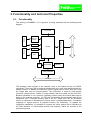
2.1. Functionality
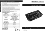
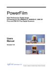
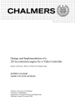
The working of RAMSES I V3 in general, is being explained with the following block
diagram.
Sync
FPGA
D-SUB
Sync
PCI-Bus
ADC
b/w or
Color
PCI-Controller
D-SUB
Sync SRAM
ADC
b/w
PLL
HController
Memory
CAN-Controller
CAN-BUS
The analogue video signals of the cameras come to the board via the two DSUBconnectors. There they will be digitized independent from each other and therefore in a
parallel manner. In addition the camera’s control signals can be used. With the FPGA
the image date can be (pre-)processed. The HController is used for card specific
functions, camera-control, control of image transfer and as a helper for the host CPU.
Because Windows is not a real-time operating system many time critical tasks can be
done by the onboard controller. Via PCI-chip the possibly pre-processed data will be
transferred into a reserved memory area of the PC, where they can be processed
further on. Because of allocating the memory as an unfragemented block, no wasteful
mappings of logical memory to physical memory are necessary. To expand the
integration capabilities, it is possible to connect the vision system with a CAN-bus via
the CAN interface, to communicate directly with systems, which are involved in the
production process.
Ramses I V3
4
User’s M an ual
2.2. Technical Facts
Color and monochrome framegrabber for high resolution industrial image
processing
Analog and digital camera interfaces
PAL/NTSC, progressive scan, line scan-cameras and further individual cameraadjustments
Video and sensor connection via 15-pole DSUB socket
Firmware- and FPGA-update directly in the system
Realtime image processing with onboard FPGA and 2MB of synch. SRAM
Driver software and programming library available for Windows and Linux
FIFO-Interface to the PCI-bus with capacity of 16kByte (optional 2-32kByte)
Onboard Hcontroller delivers 4 external TTL-IO-control circuits per channel and
serves as sensorcontroller and communication interface to the PC.
10-bit A/D converter operating at 30MHz
Power requirements: +5V/1A, +12V for CCD-camera
RAMSES I V3 is completely compatible with PCI/V2.1
Up to 5 boards per PC
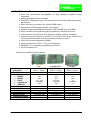
Features of the different board variants
Video IN
(alternativ)
Data Transfer
Interfaces:
•
RS 485
•
RS 232
•
LVDS
•
CameraLink
•
CAN-Bus
Camera type
I/O
2 CCD the same time
Resolution
Shades of gray
Temperature range
Dimension
Ramses I V3
PCI
B/W 2 + Color 0
B/W 1 + Color 1
approx. 100 MB/s
Compact PCI
B/W 2 + Color 0
B/W 1 + Color 1
approx. 100 MB/s
PC104+
B/W 1 + Color 0
B/W 0 + Color 1
approx.100 MB/s
yes
yes
In + Out
In design
yes
yes
yes
In + Out
In design
yes
no
yes
In
In design
no
all
4 per channel
yes
10 Bit
1024 oder 256
0 – 70 °C
104 x 144 mm
all
4 per channel
yes
10 Bit
1024 oder 256
0 – 70 °C
3HU
all
4
no
10 Bit
1024 oder 256
0 – 70 °C
116 x 98 mm
5
User’s M an ual
3. Setup
Following components are delivered:
PCI-board RAMSES I V3 for standard PCs
or
Compact PCI board RAMSES I V3 for Compact 19“ chassis
or
PC104+ PCI board for space saving industrial PCs in PC104+ formfactor
Manual
Cable for camera
3½“-floppy disc
Notice the system requirements:
min. Pentium 100 MHz with 32MByte SVGA
One PCI-Slot for Ramses I V3
Microsoft Windows Version 98/ME/NT/2000/XP
Advice: Pentium III/600, 512MB with Windows 2000/XP
In general: The faster your PC-system, the greater will be the performance of the vision
system.
3.1. Hardware-Setup
The setup is dependent on formfactor of the used RAMSES I V3 – board. Do the
following steps during the hardware setup:
3.1.1.
PCI
Power down PC and remove cover.
Plug PCI Ramses I V3 board into a PCI-slot and screw on.
Mount cover.
Connect camera with PCI-board.
Power on PC
3.1.2.
Compact PCI
Power down PC and remove cover.
Plug Compact PCI Ramses I V3 board into a PCI-slot and screw on.
Mount cover.
Connect camera with PCI-board.
Power on PC
3.1.3.
PC104+
Power down PC and remove cover.
Ramses I V3
6
User’s M an ual
Plug PCI Ramses I V3 board onto the motherboard or above and screw on.
Configure the jumper (see appendix)
Connect camera with PCI-board.
Mount cover.
Power on PC
3.2. Driver-Installation
3.2.1.
Windows 98/ME/2000/XP
If you work with Windows 98/ME/2000/XP, following steps have to be done:
Windows automatically detects the new PCI-board.
Your are asked to install the driver for the PCI-board.
Put in the delivered floppy or CD.
Then choose the file RA1V3.INF in the folder Win98_ME_2000_XP and start the
installation.
Finally Windows has to be rebooted.
3.2.2.
Windows NT
If you work with Windows NT 4.0, following steps have to be done:
Run \WinNT\setup.exe from floppy or cd.
Confirm with OK.
Finally Windows has to be rebooted.
Important Note
During Windows start-up the device driver for RAMSES I V3 (Ra1v3.sys) will be started.
He allocates continuous memory, to save the grabbed image data. If it was allocated
later, memory is fragmented, what slows down performance. Therefore after each
change of memory buffer a reboot is required.
4. Sampleapplication for Windows
4.1. Installation
The delivered application software consists of source files and the compiled version,
called VisionAppDemo.
1. Installation of the framegrabber and the driver (see chapter 3)
2. Make a directoy like c:\program files\VisionApplication
3. Copy the content of the folder SDK of the delivered disc into that folder.
Ramses I V3
7
User’s M an ual
4.2. Framegrabber Test
With the application VisionAppDemo.exe you can test the functions of the framegrabber.
At start-up following errors can occur:
Error
Action
1:PCI BIOS not present
PC-vendor / contact Feith
2:DEVICE ID not found
Check Ramses I V3 board (contact Feith)
3:Wrong Vendor ID
Check Ramses I V3 board (contact Feith)
4:Reset Controller not active
Shutdown Windows , power off PC and restart
5:Memory not allocated
Check registry-keys. See appendix
10:Board already initialized
Start application only once, possibly reboot Windows
Ramses I V3
8
User’s M an ual
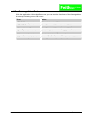
4.3. Sourcefiles
The program Vision Application Demo consists of following source files:
File
Function
VisionApplication.c
Routines of the main program
VisionApplication.h
Headerfile for VisionApplication.c
Grabber.c
Routines to realize image grabbing and display
Grabber.h
Headerfile for Grabber.c
VisionApplication.rc
Ressourcefile
Ra1V3.lib
Link-library
Ra1V3.h
Headerfile for the function library
Ra1V3.dll
The dll contains the function library and is copied into
the system32-directoy, during driver setup.
VisionAppDemo.exe
Compiled application
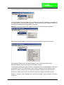
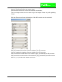
4.4. Description of the sample application
The program is designed quite simple and uses a menu and different scrollbars to
control the framegrabber.
The application menu consists of three main entries, File – Image and Tools
With File – Exit you can quit the program.
Image is responsible for starting and stopping the grab.
In addition the image can be inverted using the look-up table and saved to disc. Press
Clear to reset the image, by setting all pixels to i.e. 255, meaning white, what seems to
be a deletion of the last image.
Ramses I V3
9
User’s M an ual
In Tools there is access to different control and diagnostic commands.
In Input Interface the used video-in is marked and can be set.
Through Grabber the PCI-board can be initilized and closed. In addition it is possible to
use interrupts fpr communication purposes. This reduces cpu-load. Update Firmware is
provided for updating the framegrabber’s firmware.
Attention: Incorrect usage of the update-function can make the board unusable!
Diagnostics provides different information on the card and the connected camera:
Hardwareinfo displays soft- and hardwaredata of the used Ramses PCI-board.
Reserved Memory returns the amount of allocated memory.
Transferrate detects the current Transfer rate between PC and framegrabber. The value
is dependent on the PC motherboard, other used PCI-boards and the system’s load.
Reference voltage (neg) returns the negative reference voltage of the AD-converter.
Reference voltage (pos) returns the positive reference voltage of the AD-converter.
Range of shades of gray displays the returns the shades of gray settings of the ADconverter.
Ramses I V3
10
User’s M an ual
Camera-type returns an identification of the cameratype, connected with the current
video-in. (see libraryfunction get_camera_type)
Video Window returns the current video window’s coordinates.
Time one Image returns the time used to grab an image. Works only after grabbing
images.
With the different scroll-bars the behaviour of the AD-converter can be controlled:
High Ref changes the positive reference voltage of the AD-converter.
Low Ref changes the negative reference voltage of the AD-converter.
Gray min sets the minimal value of the shades of gray, generated by the AD-converter.
Gray max sets the maximal value of the shades of gray, generated by the AD-converter.
With X1,Y1; X2,Y2 the video window can be set.
Ramses I V3
11
User’s M an ual
5. Function Library
In this chapter the different functions of the RA1V3.DLL are explained in alphabetic
order. Following example shows the function description:
Sample function
Function:
A short description of the function.
Syntax:
The function’s syntax description in C/C++.
Description:
This section contains the job and the usage of the function. Also the
parameters are descripted.
Return:
Here you find the type and range of the return values.
Reference:
List of other routines, which have a relationship with the current function.
Note
A sample how to program the Ramses I V3 board is found in the source files of the
sample application VisionAppDemo. See chapter 4
The functions marked as intern, are not used in application development normally. But
they are used by other functions and special custom commands.
5.1. General Functions
clear_irq
Function:
Deactivates interrupthandler
Syntax:
BYTE clear_irq(BYTE card_nr);
Description:
This function deactivates the interrupthandler for the given card.
With the parameter card_nr the Ramses I V3 card to talk to is specified
(1..5).
Return:
0: Success
1: Deactivation not possible
close_ramses1
Function:
Close Ramses I V3
Syntax:
BYTE close_ramses1(BYTE card_nr);
Description:
When a card was initialized with the function init_ramses1(), it has to be
closed by this function. With the parameter card_nr the Ramses I V3
card to talk to is specified (1..5).
Ramses I V3
12
User’s M an ual
Return:
0: Success
10: Card was not initialized
Reference:
init_ramses1
get_hardware_info
Function:
Returns information about the hardware.
Syntax:
BYTE get_hardware_info(BYTE card_nr, BYTE *sw_m, BYTE
*sw_y,BYTE *hw_mode,BYTE *hw_submode, BYTE *hw_fpga);
Description:
This function returns information about the soft- and hardware using the
parameter sw_m, sw_y, hw_mode and hw_fpga. With the parameter
card_nr the Ramses I V3 card to talk to is specified (1..5).
sw_m :
sw_y:
Software Release
Software Release
Month
Year
hw_mode:
Hardware Mode
0
1
>128
= Area scan cameras
= Line scan cameras
= Custom specific
0
255
= Standard
= Custom specific
= no start-up made
50
100
150
200
= X2S50
= X2S100
= X2S150
= X2S200
hw_submode: Hardware Sub-Mode
>0
hw_fpga:
Return:
0:
1:
2:
10:
FPGA Module
Success
Command & parameter not send, error while sending
No data fetched
Card not initialized
get_memory_size
Function:
Returns the size of reserved memory.
Syntax:
BYTE get_memory_size(BYTE card_nr, DWORD *mem_size);
Description:
This functions returns the size of allocated memory in the variable
mem_size zurück.
With the parameter card_nr the Ramses I V3 card to talk to is specified
(1..5).
Return:
0: Success
1: No memory allocated
10: Card not initialized
Ramses I V3
13
User’s M an ual
get_pixel_adr (intern)
Function:
Return physical address of a memory page.
Syntax:
BYTE get_pixel_adr(BYTE card_nr, BYTE page, DWORD
*phy_adr);
Description:
This functions returns the physical address of the memory pages, given
in page.
The page count is dependent on the size of allocated memory. One
page needs 64 KB.
Calculation of the pages:
You find the size of allocated memory (in byte) in the registry.
(see appendix Registry Keys)
The division of this value through 64 kbyte delivers the count of pages.
If the memory size of card 1 has to be changed, the new value has to be
written to MemSize1. Then restart Windows.
With the parameter card_nr the Ramses I V3 card to talk to is specified
(1..5).
Return:
0: Success
1: Referred page does not exist.
10: Card not initialized
get_pixel_ptr
Function:
Returns address of memory page.
Syntax:
BYTE get_pixel_ptr(BYTE card_nr, Byte page, DWORD
*ptradr);
Description:
This functions returns the logical address of the memory pages, given in
page. With the pointer there is access to the pixeldata.
The page count is dependent on the size of allocated memory. One
page needs 64 KB.
Calculation of the pages:
You find the size of allocated memory (in byte) in the registry.
(see appendix Registry Keys)
The division of this value through 64 kbyte delivers the count of pages.
If the memory size of card 1 has to be changed, the new value has to be
written to MemSize1. Then restart Windows.
With the parameter card_nr the Ramses I V3 card to talk to is specified
(1..5).
Example:
get_pixel_ptr(1,0, &ptradr);
GPixel = (BYTE *)ptradr;
Ramses I V3
14
User’s M an ual
Return:
0: Success
1: Referred page does not exist.
10: Card not initialized
get_transfer_rate
Function:
Get the mainboard’s data transferrate
Syntax:
BYTE get_transfer_rate(BYTE card_nr, float *rate);
Description:
This function returns the motherboard’s transferrate over the pci-bus.
Result value is given in the variable rate in Mbyte/s.
With the parameter card_nr the Ramses I V3 card to talk to is specified
(1..5).
Return:
0:
1:
2:
10:
Success
Command & parameter not send, error while sending
No data fetched
Card not initialized
init_ramses1
Function:
Initialize PCI-board Ramses1
Syntax:
BYTE init_ramses1(BYTE card_nr);
Description:
This function initializes the board. It will be checked if there is a PCIBIOS, then the Device ID, the Reset Controller and the video-ins are
tested.
With the parameter card_nr the Ramses I V3 card to talk to is specified
(1..5).
Return:
0:
1:
2:
3:
4:
5:
10:
Reference:
close_ramses1
Success
PCI BIOS not present
DEVICE ID not present
Wrong Vendor ID
Microcontroller does not respond
Memory not allocated
Card already initialized.
pci_read_byte (intern)
Function:
Read one BYTE from PCI-controller
Syntax:
BYTE pci_read_byte(BYTE card_nr, WORD offset);
Description:
Reads one BYTE at the offset from PCI-controller.
With the parameter card_nr the Ramses I V3 card to talk to is specified
(1..5).
Ramses I V3
15
User’s M an ual
Return:
Read BYTE
Reference:
pci_read_word, pci_read_dword, pci_write_byte, pci_write_word,
pci_write_dword
pci_read_word (intern)
Function:
Read one WORD from PCI-controller
Syntax:
WORD pci_read_word(BYTE card_nr, WORD offset);
Description:
Reads one WORD at the offset from PCI-controller.
With the parameter card_nr the Ramses I V3 card to talk to is specified
(1..5).
Return:
Read WORD
Reference:
pci_read_byte, pci_read_dword, pci_write_byte, pci_write_word,
pci_write_dword
pci_read_dword (intern)
Function:
Read one DWORD from PCI-controller
Syntax:
DWORD pci_read_dword(BYTE card_nr, WORD offset);
Description:
Reads one DWORD at the offset from PCI-controller.
With the parameter card_nr the Ramses I V3 card to talk to is specified
(1..5).
Return:
Read DWORD
Reference:
pci_read_byte, pci_read_word, pci_write_byte, pci_write_word,
pci_write_dword
pci_write_byte (intern)
Function:
Write one BYTE to PCI-controller
Syntax:
void pci_write_byte(BYTE card_nr, WORD offset, BYTE
value);
Description:
Writes one BYTE at offset to the PCI-controller. The value to be written
is given in value.
With the parameter card_nr the Ramses I V3 card to talk to is specified
(1..5).
Return:
----
Reference:
pci_read_byte, pci_read_word, pci_read_dword, pci_write_word,
pci_write_dword
Ramses I V3
16
User’s M an ual
pci_write_word (intern)
Function:
Write one WORD to PCI-Controller
Syntax:
void pci_write_word(BYTE card_nr, WORD offset, WORD
value);
Description:
Writes one WORD at offset to the PCI-Controller. The value to be
written is given in value.
With the parameter card_nr the Ramses I V3 card to talk to is specified
(1..5).
Return:
----
Reference:
pci_read_byte, pci_read_word, pci_read_dword, pci_write_byte,
pci_write_dword
pci_write_dword (intern)
Function:
Write one DWORD to PCI-controller
Syntax:
void pci_write_dword(BYTE card_nr, WORD offset, DWORD
value);
Description:
Writes one DWORD at offset to the PCI-controller The value to be
written is given in value.
With the parameter card_nr the Ramses I V3 card to talk to is specified
(1..5).
Return:
----
Reference:
pci_read_byte, pci_read_word, pci_read_dword, pci_write_byte,
pci_write_word
receive
Function:
Receive data from Ramses board
Syntax:
BYTE receive(BYTE card_nr, DWORD *pptr);
Description:
This function reads DWORD data from Ramses’ PCI-controller. With the
parameter card_nr the Ramses I V3 card to talk to is specified (1..5)
Return:
0...127:
128:
130:
Count of DWORDs, written in pptr
no answer
Card not initialized
receive_fast
Function:
Receive DWORD from Ramses board
Syntax:
BYTE receive_fast(BYTE card_nr);
Ramses I V3
17
User’s M an ual
Description:
This function reads one DWORD from Ramses’ PCI-controller and
return the first byte.
With the parameter card_nr the Ramses I V3 card to talk to is specified
(1..5).
This function is used in conjunction with the grabb-functions. The return
value indicated, whether the grabb was successful.
Return:
0:
1:
8:
10:
Reference:
grabb_image_full, grabb_image_half
Success
Error during transferring data over the PCI - bus
Timeout
Card not initialized
receive_status
Function:
Check if there are data from Ramses board
Syntax:
BYTE receive_status(BYTE card_nr);
Description:
With this function is checked, whether there are data from Ramses
board.
With the parameter card_nr the Ramses I V3 card to talk to is specified
(1..5).
Return:
0: no answer
1: answer
10: Card not initialized
set_irq
Function:
Activates interrupthandler
Syntax:
BYTE set_irq(BYTE card_nr);
Description:
This function activates the interrupthandler for the given card.
With the parameter card_nr the Ramses I V3 card to talk to is specified
(1..5).
Return:
0: Success
1: Activation not possible
Reference:
clear_irq, set_irq_event, grabb_image_half, grabb_image_full
set_irq_event
Function:
Submit eventobject to driver
Syntax:
BYTE set_irq_event(BYTE card_nr, ULONG Event);
Description:
This function submits an eventobject to the driver, which is set, when an
interrupt occurs. So it is possible to wait for the grabb without polling a
CPU-load.
Ramses I V3
18
User’s M an ual
Event is the prior created eventobject
With the parameter card_nr the Ramses I V3 card to talk to is specified
(1..5).
Example:
hEvent = CreateEvent
(NULL, //Security Setting
FALSE, //auto reset
FALSE, //initial state non-signaled
NULL); //name string
error = set_irq_event(CARD, hEvent);
Return:
0: Success
1: Command & parameter not send, error while sending
10: Card not initialized
Reference:
grabb_image_half, grabb_image_full, set_irq, clear_irq
send_val (intern)
Function:
Send data to Ramses-board
Syntax:
BYTE send_val(BYTE card_nr, BYTE cmd, BYTE cnt DWORD
*pptr);
Description:
With this function parameter and command are sent to the Ramsesboard.
The command is found in cmd.
The count of parameters is set in cnt.
The parameters itself are accessible through the pointer pptr
With the parameter card_nr the Ramses I V3 card to talk to is specified
(1..5).
Example:
error = send_val(card_nr,
cmd,
cnt,
pptr);
Return:
0: Success
1: Command & parameter not send, error while sending
10: Card not initialized
set_memory_size
Function:
Change memory size to allocate
Syntax:
BYTE set_memory_size(BYTE card_nr, DWORD mem_size);
Description:
With this function the memory size to allocate is set. Parameter
mem_size contains the new size in byte. After this command, Windows
has to be rebooted.
Ramses I V3
19
User’s M an ual
With the parameter card_nr the Ramses I V3 card to talk to is specified
(1..5).
Return:
0: Success
1: Command & parameter not send, error while sending
10: Card not initialized
update_firmware
Function:
Update firmware of the Ramses board
Syntax:
BYTE update_firmware(BYTE card_nr, char *fname,
CALLBACK_FUNC c_func);
Description:
This function updates the firmware of the Ramses I V3 – board.
With the parameter card_nr the Ramses I V3 card to talk to is specified
(1..5).
fname is a pointer to the update file (*.bin)
With the callback-function, it is possible to realize a monitoring function.
Example:
BYTE WINAPI callback_func(int s_cnt)
{
char l_str[100];
sprintf(l_str,"%d %%",s_cnt);
SetDlgItemText(StatusHWND, IDC_STATUS, l_str);
SendDlgItemMessage(StatusHWND, IDC_PROGRESS1,
PBM_SETPOS, (WPARAM)s_cnt, 0);
return(0);
}
Return:
0:
1:
2:
3:
4:
5:
6:
7:
8:
10:
Attention:
If the update fails, the board could be unusable and has to be sent to
the vendor. Only firmware files, delivered from Feith, are allowed to be
flashed!
Ramses I V3
Success
Timeout reset hardware
Programming not ready
Memory cannot be erased
Programmer file is missing
Programmer file is too small
Timeout on PCI-board
Data error while transferring data to PCI-board
Programming error in local flash
Card not initialized
20
User’s M an ual
5.2. Area scan camera functions
get_ad_nref
Function:
Returns the negative reference voltage of the AD converter.
Syntax:
BYTE get_ad_nref(BYTE card_nr, BYTE *ref);
Description:
Returns the negative reference voltage of the current video-in’s AD
converter via the parameter ref.
With the parameter card_nr the Ramses I V3 card to talk to is specified
(1..5).
Return:
0:
1:
2:
10:
Reference:
set_ad_nref, get_ad_pref,set_ad_pref
Success
Command & parameter not send, error while sending
No data fetched
Card not initialized
get_ad_pref
Function:
Returns the positive reference voltage of the AD converter..
Syntax:
BYTE get_ad_pref(BYTE card_nr, BYTE *ref);
Description:
Returns the positive reference voltage of the current video-in’s AD
converter via the parameter ref.
With the parameter card_nr the Ramses I V3 card to talk to is specified
(1..5).
Return:
0:
1:
2:
10:
Reference:
set_ad_nref, get_ad_nref,set_ad_pref
Success
Command & parameter not send, error while sending
No data fetched
Card not initialized
get_ad_range
Function:
Read the AD-converter’s range of the shades of gray
Syntax:
BYTE get_ad_range(BYTE card_nr, BYTE *gray_min, BYTE
*gray_max);
Description:
This function return the minimal (gray_min) and maximal (gray_max)
value of gray of the current video-in’s AD-converter in the range of
0..255.
With the parameter card_nr the Ramses I V3 card to talk to is specified
(1..5).
Return:
0: Success
1: Command & parameter not send, error while sending
Ramses I V3
21
User’s M an ual
2: No data fetched
10: Card not initialized
Reference:
set_ad_range, get_ad_nref, get_ad_pref
get_camera_type
Function:
Returns detected or set camera
Syntax:
BYTE get_camera_type(BYTE card_nr, BYTE *cam_type);
Description:
Returns the detected or set camera via the parameter cam_type.
cam_type
0 = PAL
1 = NTSC
2 = XC55
3 = Jai-M1
With the parameter card_nr the Ramses I V3 card to talk to is specified
(1..5).
Before executing, the function video_present has to be called.
Return:
0:
1:
2:
10:
Reference:
video_present
Success
Command & parameter not send, error while sending
No data fetched
Card not initialized
get_inlut
Function:
Read input lookup table
Syntax:
BYTE get_inlut(BYTE card_nr,BYTE tindex, BYTE *tval);
Description:
This function reads one value of the lookup-table of the current video-in
from the FPGA.
Parameter tindex is the table-index to read from. Valid indexes are from
0 to 255.
In tval the selected table-value is written
With the parameter card_nr the Ramses I V3 card to talk to is specified
(1..5).
Return:
0:
1:
2:
10:
Reference:
set_inlut; set_video_input, get_video_input
Success
Command & parameter not send, error while sending
No data fetched
Card not initialized
get_video_window
Function:
Gets the coordinates of the present video-window.
Syntax:
BYTE get_video_window(BYTE card_nr, WORD *x1, WORD
*y1, WORD *x2, WORD *y2);
Ramses I V3
22
User’s M an ual
Description:
Gets the coordinates of the current video-in’s video-window and stores
them in the following parameters:
x1, y1:
coordinate of the upper left corner
coordinate of the lower right corner
x2, y2:
Example:
get_video_window(1,&x1,&y1,&x2,&y2);
Width = x2 - x1 + 1;
Height = y2 - y1 + 1;
With the parameter card_nr the Ramses I V3 card to talk to is specified
(1..5).
Return:
0:
1:
2:
10:
Success
Command & parameter not send, error while sending
No data fetched
Card not initialized
Reference:
set_video_window
get_video_input
Function:
Return current video-in
Syntax:
BYTE get_video_input(BYTE card_nr, BYTE *video_in);
Description:
Read current video-in of the Ramses I V3 – board and write it with the
values 0, 1 in the variable video_in.
With the parameter card_nr the Ramses I V3 card to talk to is specified
(1..5).
Return:
0:
1:
2:
10:
Reference:
set_video_input
Success
Command & parameter not send, error while sending
No data fetched
Card not initialized
grabb_image_full
Funktion:
Grab an image from an interlaced camera and store it to PC-memory
Syntax:
BYTE grabb_image_full(BYTE card_nr, BYTE page, BYTE
lflag);
Beschreibung: Grab an image from an interlaced camera at the current video-in and
store it to PC-memory. The PC-memory is reserved during Windowsstart-up from the Ramses driver.
With parameter page is controlled, in which memory page the image is
stored.
If the function set_irq is called before, after the transfer of the image to
PC-memory an interrupt will be generated. When working with
Ramses I V3
23
User’s M an ual
interrupts, it is possible to wait on the interrupt with an eventobject and
the API-function WaitForSingleObject. During this time the running
thread is not running and so it needs no CPU-power.
The parameter lflag controls whether to wait until the command finishes
(lfalg=0) or not. (lfalg=1). Then the calling routine gets back the
flowcontrol and must check with receive_fast(), whether the grab returns
errors or has finished. Lflag should be always 0 and is only set to 1,
when using switched image memory.
With the parameter card_nr the Ramses I V3 card to talk to is specified
(1..5).
Attention:
During execution no functions to read or change the configuration must
be called (i.e. get_transfer_rate, get_video_window, set_n_ref, etc.)
Example for lflag = 1, without interrupt:
error = grabb_image_full(card_nr,0,1);// Grab image to
// page 0 and return
// control back to PC
//
if(error)
// on error exit
return(error);
...
// Display image of
// page 1 or
// process it
...
while (receive_status(CARD) == 0)
{ ... }
error = receive_fast();
//
if(error)
return(error);
// Wait until the
// grab-function
// finishes
// Get result of the
// grab-function
// on error exit
error = grabb_image_full(card_nr,1,1);// Grab image to
// page 1 and return
// control back to PC
//
if(error)
// on error exit
return(error);
...
// Display image of
// page 0 or
// process it
...
while (receive_status(CARD) == 0)
{ ... }
error = receive_fast();
//
if(error)
return(error);
Return:
Ramses I V3
// Wait until the
// grab-function
// finishes
// Get result of the
// grab-function
// on error exit
0: Success
1: Command & parameter not send, error while sending
24
User’s M an ual
2:
3:
4:
10:
Reference:
No data fetched
Window too large
Transfer error
Card not initialized
set_irq, clear_irq, set_irq_event, grabb_image_half
grabb_image_half
Funktion:
Grab an image from a progressive camera and store it to PC-memory
Syntax:
BYTE grabb_image_half(BYTE card_nr, BYTE page, BYTE
lflag);
Beschreibung: Grab an image from a progressive camera current video-in and store it
to PC-memory. The PC-memory is reserved during Windows-start-up
from the Ramses driver.
With parameter page is controlled, in which memory page the image is
stored.
If the function set_irq is called before, after the transfer of the image to
PC-memory an interrupt will be generated. When working with
interrupts, it is possible to wait on the interrupt with an eventobject and
the API-function WaitForSingleObject. During this time the running
thread is not running and so it needs no CPU-power.
The parameter lflag controls whether to wait until the command finishes
(lfalg=0) or not. (lfalg=1). Then the calling routine gets back the
flowcontrol and must check with receive_fast(), whether the grab returns
errors or has finished. Lflag should be always 0 and is only set to 1,
when using switched image memory.
With the parameter card_nr the Ramses I V3 card to talk to is specified
(1..5).
Attention:
During execution no functions to read or change the configuration must
be called (i.e. get_transfer_rate, get_video_window, set_n_ref, etc.)
Example for lflag = 1, with Interrupt:
hEvent = CreateEvent(NULL,
//Security Setting
FALSE,
//Auto Reset
FALSE,
//initial state non-signaled
NULL);
//name string
error = set_irq_event(CARD, hEvent);
set_irq;
// activate interrupthandler
error = grabb_image_half(card_nr,0,1);// Grab image to
// page 0 and return
// control back to PC
//
if(error)
// on error exit
return(error);
...
Ramses I V3
...
// Display image of
// page 1 or
// process it
wait = 10000;
WaitForSingleObject(hEvent,wait)
// Timeout 10sec
// Wait until grab
25
User’s M an ual
// finishes
//
error = receive_fast();
//
if(error)
return(error);
// Get result of the
// grab-function
// on error exit
error = grabb_image_half(card_nr,1,1);// Grab image to
// page 1 and return
// control back to PC
//
if(error)
// on error exit
return(error);
...
// Display image of
// page 0 or
// process it
...
wait = 10000;
WaitForSingleObject(hEvent,wait)
// Timeout 10sec
// Wait until grab
// finishes
//
error = receive_fast();
// Get result of the
// grab-function
//
// on error exit
if(error)
return(error);
clear_irq;
// deactivate interrupthandler
Return:
0:
1:
2:
3:
4:
10:
Success
Command & parameter not send, error while sending
No data fetched
Window too large
Transfer error
Card not initialized
Reference:
grabb_image_full, set_irq_event, set_irq, clear_irq
set_ad_nref
Function:
Set negative reference voltage of the AD converter.
Syntax:
BYTE set_ad_nref(BYTE card_nr, BYTE ref);
Description:
This function sets the negative reference voltage of the current videoin’s AD-converter with ref (0..255). The minimal voltage is 0V, the
maximum 1,2V. The function can be used to improve contrast. Attention:
The negative voltage must not be greater than the positive.
With the parameter card_nr the Ramses I V3 card to talk to is specified
(1..5).
Return:
0: Success
1: Command & parameter not send, error while sending
Ramses I V3
26
User’s M an ual
2: No data fetched
10: Card not initialized
Reference:
set_ad_pref, get_ad_nref, get_ad_pref
set_ad_pref
Function:
Set positive reference voltage of the AD converter.
Syntax:
BYTE set_ad_pref(BYTE card_nr, BYTE ref);
Description:
This function sets the positive reference voltage of the current video-in’s
AD-converter with ref (0..255). The minimal voltage is 0V, the maximum
1,2V. The function can be used to improve contrast. Attention: The
positive voltage must not be greater than the negative.
With the parameter card_nr the Ramses I V3 card to talk to is specified
(1..5).
Return:
0:
1:
2:
10:
Reference:
set_ad_nref, get_ad_nref, get_ad_pref
Success
Command & parameter not send, error while sending
No data fetched
Card not initialized
set_ad_range
Function:
Set the AD-converter’s range of the shades of gray
Syntax:
BYTE set_ad_range(BYTE card_nr, BYTE gray_min, BYTE
gray_max);
Description:
This function sets the minimal (gray_min) and maximal (gray_max)
value of gray of the current video-in’s AD-converter in the range of
0..255, where gray_min < gray_max.
With the parameter card_nr the Ramses I V3 card to talk to is specified
(1..5).
Return:
0:
1:
2:
10:
Reference:
get_ad_range, get_ad_nref, get_ad_pref
Success
Command & parameter not send, error while sending
No data fetched
Card not initialized
set_inlut
Function:
Set input lookup table
Syntax:
BYTE set_inlut(BYTE card_nr, BYTE tindex, BYTE tval,
BYTE write_flag);
Description:
This function sets the lookup-table of the current video-in in the FPGA.
The data have to be sent sequentially and are cached on the Ramses-
Ramses I V3
27
User’s M an ual
board until write_flag is switched from 0 to 1.
Paramter tindex is the table-index of the value tval.
With the parameter card_nr the Ramses I V3 card to talk to is specified
(1..5).
Example to invert image:
for (i=0; i<255;i++)
{
set_inlut(CARD,i,~i,0); //send table values
}
//from index 0..254
error = set_inlut(CARD,i,~i,1);//send table value 255
//and commit
Return:
0:
1:
2:
10:
Success
Command & parameter not send, error while sending
No data fetched
Card not initialized
Reference:
get_inlut, set_video_input, get_video_input
set_video_input
Function:
Set video-in channel
Syntax:
BYTE set_video_input(BYTE card_nr, BYTE video_in);
Description:
Set the video-in of the Ramses I V3 – board to the channel given in the
parameter video_in (values: 0, 1). This channel is implicitly used by
many other functions.
With the parameter card_nr the Ramses I V3 card to talk to is specified
(1..5).
Return:
0:
1:
2:
10:
Reference:
get video_input
Success
Command & parameter not send, error while sending
No data fetched
Card not initialized
set_video_window
Function:
Sets the coordinates of the current video-window.
Syntax:
BYTE set_video_window(BYTE card_nr, WORD x1, WORD y1,
WORD x2, WORD y2);
Description:
Sets the coordinates of the current video-in’s video-window.
x1, y1:
coordinate of the upper left corner
x2, y2:
coordinate of the lower right corner
The x-coordinates for für PAL/CCIR have a range from 0 to 767, the
y-coordinates from 0 to 575.
Ramses I V3
28
User’s M an ual
(X2 – X1 +1) has to be divisible through 4, due to a limitation of of the
PCI-bus.
With the parameter card_nr the Ramses I V3 card to talk to is specified
(1..5).
Example:
//
x1
y1
x2
y2
768 x 576 grab image
= 160;
//skip unusable edges
= 44;
= 927;
// x1 + 768 - 1
= 619;
// y1 + 576 - 1
set_video_window(1,x1,y1,x2,y2);
grabb_image_full(1,0,1,0);
//
x1
y1
x2
y2
768 x 288 grab images
= 160;
= 44;
= 927;
// x1 + 768 - 1
= 331;
// y1 + 288 - 1
set_video_window(1,x1,y1,x2,y2);
grabb_image_full(1,0,1,0);
With the parameter card_nr the Ramses I V3 card to talk to is specified
(1..5).
Attention:
Values will be reset to the standard, if function video_present is called!
If interlaced cameras are used, the y-coordinates are rounded back to
the last full image. So it is only possible to change the y-coordinates in
steps of 2.
Return:
0:
1:
2:
3:
10:
Success
Command & parameter not send, error while sending
No data fetched
Width not modulo 4
Card not initialized
Reference:
get_video_window, video_present
video_present
Function:
Check current video-in
Syntax:
BYTE video_present(BYTE card_nr);
Description:
This function checks the current video-in, if there is a video-signal. If so,
the parameter fitting the detected camera are set:
Video-window: Can be checked with get_video_window.
PAL
= 768 x 576
NTSC
= 640 x 480
XC55
= 640 x 480
HR70
= 1024 x 768
Jai-M1 = 1280 x 1024
Ramses I V3
29
User’s M an ual
Camera-type: Can bechecked with get_camera_type.
With the parameter card_nr the Ramses I V3 card to talk to is specified
(1..5).
Return:
0:
1:
2:
3:
10:
Reference:
get_video_window, get_camera_type, get_video_input, set_video_input
Ramses I V3
Success
timeout
no vsync-signal
no hsync-signal
Card not initialized
30
User’s M an ual
6. Glossary
BNC
Shortform for "Bayonet Neill Concelmann". The BNC connector is a
bayonett connector to connect two coax cable.. BNC-connectors are
designed for RG-58-cables (Ethernet) and RG-59-cables (Video)
The abbreviation stands also for Bayonet-Navy-Connector, BritishNaval-Connector and Baby-N-Connector.
Busmastering
Enables a device, connected to the PCI-bus, to control its traffic itself.
So it is possible for certain devices, for example the harddisc-controller
or a framegrabber, to transfer data over the PCI-bus into main memory
without using the host-CPU. This increases performance, because the
processor can do some other jobs during the transfer.
CameraLink
Definition for high performance datatransfer. In contrast to LVDS,
connectors are defined too. CameraLink is used increasingly for
communication purposes (includes data transfer) with camera systems.
CCD
This abbreviation stands for Charge Coupled Device. These
photosensitive, microelectronical components transform light to
proportinal electrical signals. A CCD- sensor consists of several CCDelements, either in a line (for scanners or linescan cameras) or in a
matrix (for area scan cameras). CCD-elements only react with
brightness, so for every ground color a filter has to be applied.
CCIR
A former standard to digitize images.
DMA
Direct Memory Access describes a possibility for certain devices like
harddisc-controller, sounddevices or even framegrabber, to access main
memory without using the host’s cpu.
D-SUB
Heteropolar plug connector
FPGA
Field Programmable Gate Array, an electronical component, which can
be programmed free.
Framegrabber
Addon board for PCs, which records a video signal, digitizes it and
writes the digital image into the host’s memory. Powerful framegrabber
additionally offer onboard image processing.
LVDS
Short for Low Voltage Digital Signal and describes a standard for high
speed data transfer. LVDS is common to use for communication
purposes with cameras.
Ramses I V3
31
User’s M an ual
NTSC
Color coding process commonly used in USA and Japan. In contrast to
PAL, pase errors cannot be corrected from receiver. This leads to
considerable color jumps between different channels.
PAL
Color coding process, which reduces the color errors, originated during
transmission, to smaller, less conspicuous color saturation errors
PCI
A 1991 introduced standard for PC-board, which expands vastly the
possibilties. The bus has a width of 32 bit with frequency of 33 MHz,
what enables transfer rates up to 133mbytes/s. Extensions like Plug &
Play are possible and additional boards are able to access main
memory without using the host’s cpu (DMA, Busmaster).
RS232
Interface for serial data transfer up to 20 kbit/Second in both direction.
Maximal cablelength 15m.
RS422
Interface for serial data transfer up to 10 mbit/s in both direction.
Maximal cablelength 1200m.
RS485
Extension to RS422 with more transceivers.
TTL
Short for Transistor-Transistor-Logic and stands for circuit family.
VSYNC/HSYNC
Video signals for horizontal and vertical synchronisation.
WDM
Short for "Windows Driver Model". It describes the way to develop und
integrate new drivers for Windows.
Ramses I V3
32
User’s M an ual
Appendix A
A.1 Registry Keys
A.1.1
Memory
Windows NT
HKEY_LOCAL_MACHINE\System\CurrentControlSet\Services\Ra1V3\Parameters\
MemSize1
MemSize2
MemSize3
MemSize4
MemSize5
Memorysize for card 1 in byte
Memorysize for card 2 in byte
Memorysize for card 3 in byte
Memorysize for card 4 in byte
Memorysize for card 5 in byte
Windows 98/ME/2000/XP
HKEY_LOCAL_MACHINE\System\CurrentControlSet\Services\Ramses1V3\Parameters\
MemSize1
MemSize2
MemSize3
MemSize4
MemSize5
Ramses I V3
Memorysize for card 1 in byte
Memorysize for card 2 in byte
Memorysize for card 3 in byte
Memorysize for card 4 in byte
Memorysize for card 5 in byte
33
User’s M an ual
A.2 Pin Layout
A.2.1
DSUB15, 15-pol. socket
PIN
Description
1
Signal A
2
*Signal A
3
Signal B
4
Video In
5
*Signal B
6
GND
7
+12 Volt
8
-12 Volt
9
Vcc
10
Signal C (TTL - Out0)
11
*Signal C (TTL - Out1)
12
Signal D (TTL - Out2)
13
*Signal D (TTL- In 0)
14
TxD (TTL - In 1)
15
RxD (TTL - In 2)
TTL - In/Out are not supported in the standard version. But it is possible to integrated
that.
Ramses I V3
34
User’s M an ual
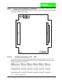
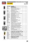
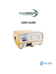
A.2.2
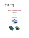
Jumper and signallines on PC104+
To work correctly, there must be set some jumpers on the PC104-board. In the following
the position of the jumpers visible:
JP3
JP5
JP2
JP4
ISA-BUS
PCI-BUS
JP1
J3
J1
A.2.2.1
1
15
1
Configurationjumper JP1 – JP5:
In every block only one connector between first and second line has to be set. In the
following is assumed, that the right pin pair is bridge 1. Dependent on the mount level,
following jumpers have to be set:
Level
JP1
JP2
JP3
JP4
JP5
1
1
1
1
1
1
2
2
2
2
2
2
3
3
3
3
3
3
4
4
3*)
3*)
4
4
JP1:
Ramses I V3
Definition Interrupt line
35
User’s M an ual
JP2:
JP3:
JP4:
JP5:
Grant Signal
Bus-Request Signal
Device-Select
PCI-Clock
*)If the board<is mount on level 4, the device on level 3 must not need the signals for
Bus-Request and Grant.
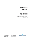
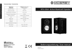
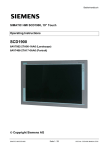
Example:
Board is mount on level 1, that means directly on the motherboard. So the jumpers have
to be set as follows:
JP1
A.2.2.2
JP3
JP5
JP2
JP4
Connector J1 and J3
Signalconnector J1 for additinal power supply:
PIN
Description
1
12V
2
*GND
3
GND
4
Vcc
Signalconnector J3 to connect camera:
PIN
Description
1
Signal A
2
Vcc
3
*SignalA
4
Signal C
5
Signal B
6
*Signal C
7
Video In
8
Signal D
9
*Signal B
10
*Signal D
11
GND
Ramses I V3
36
User’s M an ual
12
TxD
13
12V
14
RxD
15
-12V
16
GND
Ramses I V3
37
User’s M an ual
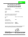
DECLARATION OF CONFORMITY
EU-KONFORMITÄTSERKLÄRUNG
DECLARATION DE CONFORMITÉ
Wir (Name des Anbieters)
We (Suppliers Name)
Nous (Nom du Fournisseur)
Feith Sensor to Image GmbH
Anschrift
Address
Adress
Lechtorstrasse 20
D-86956 Schongau
erklären in alleiniger Verantwortung, daß das Produkt:
declare under sole responsibility, that the product:
déclarons sous notre responsibilité, que le produit:
Bezeichnung
Name
Nom
Ramses 1 V3 PCI Frame Grabber
Typ, Modell, Artikel-Nr.
Type, Model, Article No.
Type, Modèle, No. d’ Article
RA1V3
mit den Anforderungen der Normen
fullfills the requirements of the standard
satisfait aux exigences des normes
EN 55022
EN 50081-1/2
EN 50082-11/2
übereinstimmt und damit den Bestimmungen der EU-Richtlinie 89/336/EWG entspricht.
and therefore corresponds to the regulations of the EU-Directive 89/336/EEC.
et, ainsi, correspond aux reglement de la Directive du Conseil 89/336/CCE.
Schongau, 01.07.2003
(Geschäftsführer)
Ort und Datum der Ausstellung
Place and Date of Issue
Lieu et date d ‘ établissement
Name und Anschrift des Befugten
Name and Signature of authorized person
Nom et signature de la personne autorisée
Ramses I V3
38
User’s M an ual