1
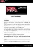
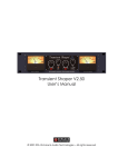
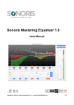
Wire Grind
Advanced Noise Gate v1.8
User Manual
December 15, 2014
5.2
Contents
Gating Controls . . . . . . . . .
Threshold Level Meter . . . . .
Threshold . . . . . . . . . . . .
Attack . . . . . . . . . . . . . .
Release . . . . . . . . . . . . .
Hold . . . . . . . . . . . . . . .
RMS Win . . . . . . . . . . . .
Attack Envelope: synth/slow .
Channel Processing: indi/linked
Gating Mode: std/duck . . . .
Detection Method: peak/rms .
Max Gate/Min Gate Meters . .
Attack Delay . . . . . . . . . .
Note Truncate . . . . . . . . .
Triggered Muting . . . . . . . .
Beat Skip . . . . . . . . . . . .
Output Signal . . . . . . . . . .
Gate Open . . . . . . . . . . .
Gate Closed . . . . . . . . . . .
1 Overview
2
2 Features
2
3 Specifications
3.1 Difference between Demo Version and Full Version . . . . . .
3.2 Difference between VST2 and
VST3 versions . . . . . . . . .
3
4 Installation
4
5 Controls
5.1 Control Signal . . . . . . . . .
About Side Chaining . . . . .
Adjusting the Control Signal
Control Bands . . . . . . . .
Bypass . . . . . . . . . . . . .
Ctrl . . . . . . . . . . . . . .
4
4
4
5.3
4
4
4
4 6 Footnotes
.
.
.
.
.
.
3
3
1
4
4
5
5
5
5
5
5
5
6
6
6
6
6
6
6
6
7
7
8
1
Overview
This product can be used for noise reduction, and just as any other audio effect, it can also
be used for creative sound shaping. The software includes a set of advanced features which
are found in no other product.
Wire Grind Advanced Noise Gate is the world’s premier noise gate effect. It has all the
features you would expect on a top of the line noise gate and more. Spectrally conscious
gating, and multi-band output with a separate range1 setting for each band. Side chaining2 ,
two attack envelopes, independent and linked channel processing, ducking, peak and RMS
level detection, surround sound processing capability.
Advanced gating Controls
There are also many advanced features found nowhere else. Delay the onset of envelope
with Attack Delay, cut notes off early with Note Truncate, force the gate to stay closed with
Triggered Muting, and use our Beat Skip feature to probabilistically mute entire beats in real
time.
Advanced Equalization Controls
Advanced Noise Gate uses special equalizers. The control signal has a three band equalizer
with strong band separation. The output signal has a special split three band equalizer
with six levels controls. These controls can provide multi-band range. They also offer other
possibilities such as gating on one band while ducking on another.
Anti-Clicking Technology
Advanced Noise Gate uses anti-clicking technology. Other noise gates can create a clicking
noise when using short attack times. In contrast, Advanced Noise Gate produces almost no
clicking noise, even when using attack times under 1 ms.
Carefully Tuned Envelopes
Advanced Noise Gate uses envelopes specially sculpted to have a pleasant musical sound.
The release envelope mimics the decay of a real instrument. There are also two optional
attack envelopes: One models the envelope of an analog synthesizer. The other produces
a smooth gradual volume swell that can be more perceptually pleasing with longer attack
times.
2
Features
• Mono, stereo, and multi-channel processing
• Side channel processing2
• Anti-clicking technology
• Attack envelope delay
• Note length truncation
• Triggered muting
• Probabilistic gating
• Peak and RMS level detection
2
• Process channels independently or link them together
• Two attack envelope shapes
• Slow volume effect
• Three-band weighting of input signal
• Three-band output with separate gain adjustment for both the ”open” and the ”closed”
states. This feature is equivalent to multi-band range1 control.
• VU meter displaying both highest and lowest channel levels
• Dual gate level meters displaying both the most open and most closed gate levels.
3
Specifications
• Supported Sample Rates: 44.1kHz, 48kHz, 88.2kHz, 96kHz. Advanced Noise Gate is
expected to work for any sample rate between at least 11.025kHz and 384kHz, although
this has not been tested. Running the demo at the sample rate in question should give
a very good indication of whether or not it works at that sample rate. s
• Supported Channel Formats: Many channel formats are supported (mono, stereo,
quadro, 5.1, 7.1,... 13.1, etc)3 .
• Operating System: Windows XP, Windows Vista, Windows 7 (OSx is yet to be supported)
• Plug-in Versions:
VST2, 32-bit
VST2, 64-bit
VST3, 32-bit
VST3, 64-bit
• Internet: Access to the world wide web is required during installation.
• Supported Host Programs: We do not have many resources for testing hosts. Trying
the demo version should give a good indication of whether the full version will work.
3.1
Difference between Demo Version and Full Version
There are currently four full versions of the Wire Grind Advanced Noise Gate. There
are also four demo versions. There are two differences between the demo versions the
full versions: 1) The demo versions are unable to save settings and 2) The output of
the demo version is modulated for 3 of every 18 seconds.
3.2
Difference between VST2 and VST3 versions
The VST2 version does not support side chaining.
3
4
Installation
This program comes with a set up application. This application is able to install all four
versions of the plugin.
5
5.1
Controls
Control Signal
About Side Chaining
Depending on your set up, the control signal may be either the input signal or the side
chain signal. Side chaining2 is enabled automatically whenever the auxiliary input is active.
Likewise, when the auxiliary input becomes inactive, Advanced Noise Gate automatically
resumes normal operation.
Adjusting the Control Signal
The control signal of this effect is split into three frequency bands: lo, mid, hi. The level of
each band is adjusted independently.
Freq 1: The band edge between the low band and the mid band.
Freq 2: The band edge between the mid band and the high band.
In Gain: The amount of gain applied to the control signal.
Control Bands
Low: The amount of gain for the low frequency band.
Mid: The amount of gain for the middle frequency band.
High: The amount of gain for the high frequency band.
Bypass
When engaged, the raw input signal become the output.
Ctrl
When engaged, the processed control signal becomes the output.
5.2
Gating Controls
Threshold Level Meter
This feature monitors the level of the control signal. When Channel Processing is set to
LINKED, the meter functions like a normal level meter. When Channel Processing is set
4
to INDI, the meter may be lit up in the center. The top of the lit up area is the maximum
of the control signal channels. The bottom of the lit up area is the minimum of the control
signal channels. If the level meter displays a horizontal line one pixel high, then all control
signal channels are at the same level.
Threshold
When the input level is above the threshold, the gate opens. When the input level is below
the threshold, the gate closes.
Attack
The time it takes for the gate to open. The time is given as the T60, which is the time it
takes the signal level to increase by 60 dB.
Release
The time it takes for the gate to close. The time is given as the T60, which is the time it
takes the signal level to decrease by 60 dB.
Hold
An effect known as ”chatter” can be produced when a noise gate rapidly opens and closes.
Increase the hold to prevent this. Decrease it if you would like to a slightly faster response
time on the release.
RMS Win
This feature is only available when RMS mode is enabled. Higher RMS times can be used to
minimize the affect of momentary volume spikes, and, at times, be better suited for detecting
more droned out sounds. Lower RMS times will result in a behavior approaching that of
peak mode. Peak mode responds faster than RMS. Peak mode is better at capturing the
very beginning of a note, such as when the crack or the crunch of a note are important.
Attack Envelope: synth/slow
This option provides a choice of two attack envelopes.
1. SYNTH: The gate opens quickly, and then increases slightly until the maximum is
reached. This has been modeled off of a synthesizer attack envelope.
2. SLOW: The gate opens gradually creating a smooth volume swell.
Channel Processing: indi/linked
This option provides a choice of two processing modes.
1. INDI: All control signal channels are analyzed separately, and separate operations are
performed on each output channel.
2. LINKED CH: All control signal channels are analyzed together, and the same operations are performed on each output channel.
5
Gating Mode: std/duck
This option provides a choice of two gating modes.
1. STD: The gate attacks when the input level is above the threshold and it releases when
the input level is below the threshold. This is the standard operation for a traditional
noise gate.
2. DUCK: The gate releases when the input level is above the threshold, and it attacks
when the input level is below the threshold. This is often referred to as ”ducking”.
Detection Method: peak/rms
This option provides a choice of two methods for measuring the level of the control signal.
1. PEAK: The input level is measured as the peak of the waveform.
2. RMS: The input level is measured as the RMS of the waveform.
Max Gate/Min Gate Meters
Monitor the state of the gates. When the gate opens, the meter lights up, and when it closes,
the meter goes dark. There is one meter for the gate that is most open (labeled as max ),
and another meter for the gate that is most closed (labeled as min). The second meter is
locked to the first when the Channel Processing is set to LINKED.
Attack Delay
Delays the onset of the attack.
Note Truncate
This isolates the onset of a note from the rest of the signal. In other words, it truncates the
note causing the gate to close sooner than it would otherwise.
Triggered Muting
This forces the gate to remain closed for a given amount of time. It is triggered when the
signal level passes from above the threshold to below the threshold.
Beat Skip
This feature causes notes to be muting out entirely. It is set as a percentage of the envelopes
which will be muted. It is triggered in a statistically random fashion.
5.3
Output Signal
The output of this effect is split into three frequency bands: lo, mid, and hi. Each band is
in turn split into two paths: open and closed. The output level for each band and each path
is controlled independently. This is equivalent to multi-band range1 control.
Freq 1: The band edge between the low band and the mid band.
6
Freq 2: The band edge between the mid band and the high band.
Out Gain: The amount of gain applied to the output signal.
Gate Open
Low: The amount of gain for the low frequency band when the gate is open.
Mid: The amount of gain for the middle frequency band when the gate is open.
High: The amount of gain for the high frequency band when the gate is open.
Gate Closed
Low: The amount of gain for the low frequency band when the gate is closed.
Mid: The amount of gain for the middle frequency band when the gate is closed.
High: The amount of gain for the high frequency band when the gate is closed.
7
6
Footnotes
1. Range is calculated from 0 dB.
2. Feature is only supported in the VST3 version of Advanced Noise Gate.
3. Channel format may be limited by either your host application or your computer
hardware.
8