1
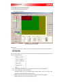
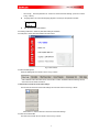
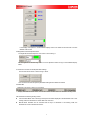
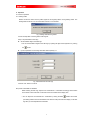
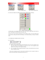
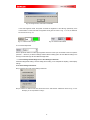
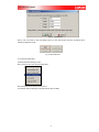
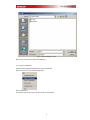
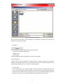
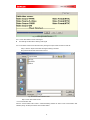
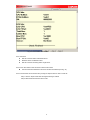
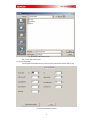
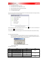
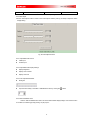
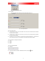
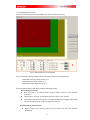
USER’S MANUAL
FOR
VPU 3000 SOFTWARE
VERSION: V1.3
VPU 3000 SOFTWARE
Revision History
Revision
Date of
Revision
Description
Revised by
1.1
2006-11-07
This is the first revision.
Sureone
1.2
2006-12-18
Modified support connection address.
Sureone
1.3
2006-12-27
Updated the software.
Sureone
1
VPU 3000 SOFTWARE
Table of Contents
1.
.ABBREVIATION DEFINITION ...................................................................................... 1
2.
.SOFTWARE FUNCTIONS ............................................................................................. 1
3.
.WORKING SYSTEM REQUIREMENT.......................................................................... 1
3.1 SYSTEM REQUIREMENTS .............................................................................................. 1
3.2 EQUIPMENT W IRING REQUIREMENT .............................................................................. 1
4.
.INSTALLATION AND START-UP .................................................................................. 1
4.1 INSTALLATION ............................................................................................................... 1
4.2 START-UP AND COMMUNICATION SETTINGS ................................................................... 1
5.
.VPU 3000 SOFTWARE INTERFACE INTRODUCTION ............................................... 3
5.1 VPU 3000 SOFTWARE INTERFACE INTRODUCTION ....................................................... 3
5.2 MENU BAR ................................................................................................................... 3
5.3 ADVANCEDD SETTINGS BAR .......................................................................................... 4
5.4 SHORTCUTS TO RESUME THE SAVED VIDEO SETTINGS .................................................... 4
5.5 VIDEO SOURCE SWITCH BAR ........................................................................................ 4
5.6 BRIGHTNESS & GAMMA ADJUSTMENT BAR .................................................................... 5
5.7 SHORTCUTS TO RESUME THE SAVED PARAMETERS SETTINGS ......................................... 5
5.8 STATUS BAR ................................................................................................................. 5
6.
.OPERATION .................................................................................................................. 6
6.1 COMMON OPERATION ................................................................................................... 6
6.1.1 SETTING GUIDE ......................................................................................................... 6
6.1.2 SELECT THE VIDEO SOURCE AND DISPLAY MODE ....................................................... 8
6.1.3 SET BRIGHTNESS & GAMMA PARAMETERS FOR LED SIGN ........................................ 9
6.1.4 FETCH SETTINGS/ SAVE SETTINGS AS FILE / SAVE SETTINGS TO SHORTCUTS ........... 10
6.1.4.1 SAVE SETTINGS TO SHORTCUTS ........................................................................... 10
6.1.5 REFRESH ................................................................................................................ 13
6.2 ADVANCEDD SETTING ................................................................................................. 13
6.2.1 SEARCH SIGNAL ...................................................................................................... 13
6.2.2 COMMUNICATION TEST ............................................................................................ 14
6.2.3 SYSTEM PARAMETERS ............................................................................................. 16
6.2.4 VIDEO ADJUST ........................................................................................................ 18
6.2.5 COLOR TEMPERATURE ADJUST ................................................................................ 19
6.2.6 VIDEO DISPLAY ZOOM CONTROL .............................................................................. 20
2
VPU 3000 SOFTWARE
1.
.Abbreviation
Definition
VPU3000 :Video Processing Unit 3000
LDU3000:LED Distribution Unit 3000
2.
.Software Functions
2.1
Automatic detecting of available video sources.
2.2
Video zoom control. Full screen display / Full screen width auto adaptation / Full screen height auto
adaptation / Window partial display.
Zoom control from 10% to 160%.
2.3
Many display modes available: Figure in Figure / Float & overlay, etc.
2.4
Individual setting for video’s brightness & color & gray level of video.
2.5
Automatic detecting of work status of equipment currently connected the versions of VPU & LDU and
light sensor status.
2.6
Can save and resume all the parameter settings.
2.7
LED sign’s color temperature adjustment.
2.8
Coordinates & size setting for Display windows (LED sign display window / Video display window / DVI
display window)
3.
.Working System Requirement
3.1 System Requirements
•
Intel Pentium or Celeron MAX 533 MHz CPU or higher or compatible system
•
RAM: 128MB or more
•
Available USB port or serial port (RS232)
•
CD-ROM drive
•
Windows 2000, windows XP or Windows 2003 operate system
•
Displaying mode: 1024x768, 16 Byte at least
•
Font of operating system: Small font
3.2 Equipment Wiring Requirement
Before running this VPU 3000 software, please make sure to connect correctly the following equipment:
VPU3000, LDU3000, and Video source (like DVD or other equipment), DVI input and make sure these
equipments can work normally.
4.
.Start-up
4.1 Preparation before startup
Connect all relative equipment and the control PC. If you want to connect the control PC with the
VPU3000 via USB, please refer to the manual Universal converter winxp A3 20060901.pdf and
install USB/COM Port drive program.
4.2 Start-up and Communication Settings
4.2.1
Click the file VideoControl.exe file to run the VPU 3000 software
Choose Start\All programs\Imposa software\VPU, or double click VPU 3000.exe in folder System disk directory
\Program Files\IMPOSA\Imposa Software\ VPU 3000\.VPU 3000.exe Fig. 1
1
VPU 3000 SOFTWARE
Fig. 1 VPU 3000 Start-up Interface
The VPU 3000 software will detect the available input signals (DVI & Video Sources) and read
the setting of VPU3000 and firmware version. All these information will be displayed on the VPU 3000
software’s interface.
4.2.2 Communication settings. When you run this software for the first time, or if the last communication
settings are invalid, you will see Communication Set window require you to do the communication
settings.
Fig. 2 Communication Setting
Please select the correct COM port you are using for communication. The baud rate is 19200 and
is not changeable. Click Test button to test the communication between control PC & VPU.
If you see the prompt window as shown in Fig. 3 below, please go the next step. If you see the
prompt window as shown in Fig. 4, please check whether you have selected the correct COM port in the
communication setting window. If you are using USB to connect the VPU3000 for communication, please
check whether you have installed the USB/COM port drive program to your control PC.
Fig. 3: Communication OK
Fig. 4: Communication Failed
2
VPU 3000 SOFTWARE
5.
.VPU 3000 Software Interface Introduction
5.1 VPU 3000 software interface introduction
Main interface of VPU 3000:
Fig. 5 Main Interface of VPU 3000
5.2 Menu Bar
As shown in the area 1 in Fig. 5 above, in the menu bar, there are File menu & Wizard menu & Help menu.
5.2.1 In the file sub-menu, you will have: Communication Set, Import Configuration, Export Configuration, Save
Config, Language Select, Exit.
Communication Set: Setting for communication, please refer to 4.2.2 above for details.
Import Configuration / Export Configuration
Parameters Setting: LED sign brightness setting, Gamma setting, Video zoom control, Color
temperature setting, Video display adjustment setting.
-
Import Configuration: Open the saved parameters setting file and send to the VPU3000
-
Export Configuration: Save the parameters settings to a file.
3
VPU 3000 SOFTWARE
Save Config:
-
Save the parameters to “ Shortcut to resume the saved settings” (as shown in area 6
at Fig.. 5 above)
Language Select: To choose the language (English or Chinese) for the operation interface.
Exit: To exit the VPU 3000 software
5.2.2 Setting Guide menu: Guide for parameters setting for VPU3000.
5.2.3 Help menu: About VPU 3000 Software as shown below
Fig. 6 About window
5.3 Advanced Settings Bar
Advanced Settings Bar is as shown in area 1 in Fig. 5 above.
Select different buttons like Video Zoom Control button to switch to different advanced settings window,
which will be shown below the buttons.
5.4 Shortcuts to resume the saved video settings
The shortcuts to resume the saved video settings are as showed in area 3 in the Fig. 5 above.
Select Video 1 to Video 4 buttons to resume the saved Video settings
5.5 Video Source Switch Bar
The Video source switch bar is as shown in area 4 in Fig. 5 above
4
VPU 3000 SOFTWARE
In the display mode options to choose different display mode. In the Video source switch bar to choose
different Video source.
5.6 Brightness & Gamma Adjustment Bar
The brightness & Gamma adjust bar is as shown in area 5 at Fig. 5.
Set the brightness for the LED sign. Gamma can be adjusted to make the sign to have different display
effect.
5.7 Shortcuts to resume the saved parameters settings
The shortcuts are as shown in area 6 at Fig. 5 above.
Click one of the shortcuts to open the parameters setting file and refresh the window.
5.8 Status Bar
Status bar is as shown in area 7 in Fig. 5 above.
Display VPU3000’s firmware version, such as CPU version & FPGA version & VPU3000’s working mode
VPU 3000 has two following working modes:
Communication Mode: This is referring to the top line information displayed in the VPU3000’s LCD. In this
working mode, the VPU3000 can receive data from control PC.
Manual Mode: VPU3000 can be controlled with the keys on VPU3000. In this working mode, the
VPU3000 can not be controlled with the PC.
5
VPU 3000 SOFTWARE
6.
.Operation
6.1 Common Operation
6.1.1 Setting Guide
Please connect the Video sources (Video Signals & DVI Signals) before running Setting Guide. The
Setting Guide will fail to run if one of the Video sources is not connected
Fig. 7 Setting Guide Running Failed
Go the next step after connecting all the Video signals:
Step 1: Set parameters for LED sign
●
Set the width & height of the LED sign
♪ You can set the width & height for the LED sign by inputting the digits in the keyboard or by clicking
the
●
button
Input the quantities of connecting LDU 3000. Default quantity is 1.
Fig. 8 Set Parameters for LED Sign
Click the “next” button to continue:
Step 2: Set Coordinates for LDU3000
While watching the LED sign, adjust the X coordinates & Y coordinates accordingly. Please make
sure to leave 2 extra white dots on each side of the four boarders of the display area.
♪ You can adjust the X coordinates & Y coordinates by clicking the button
. Please wait a while
(the setting needs time to be transmitted to the LDU from VPU) and watch the display on the LED
sign after you have adjusted the coordinates.
6
VPU 3000 SOFTWARE
Fig. 9
Coordinate setting window of LDU
Click the “Next” button to continue:
Step 2: Set Offset Value for LDU Video
While watching the LED sign, adjust the Row Offset Value & Column Offset Value coordinately. Please
make sure there is no black boarder on each boarder of the display area.
♪ You can adjust the Offset Value by clicking the button
. Please wait a while (the setting needs
time to be transmitted to the LDU from VPU) and watch the display on the LED sign after you
have adjusted the coordinates.
Fig. 10:
Set Offset Value for LDU Video
Click “Finish” button and the following prompt will pop out:
7
VPU 3000 SOFTWARE
Fig. 11:
LDU Setting Report
Click the “OK” button to exit the Setting Guide. Check the display status, if you are not satisfied with the
display effect, you can run the Setting Guide once again and adjust the settings.
6.1.2 Select the Video Source and Display Mode
6.1.2.1 Display Mode
Five display modes available:
DVI Only
Video Only
DVI above AV
AV above DVI
DVI and AV intercrossed
Display mode should be changed according to different application. If no DVI signal is connected when DVI
signal is selected, you will get an “Error Report”. When display mode is changed, the video source selection
will be changed accordingly.
If “DVI only” is selected, but there is no DVI signal connected, you will get an “Error Report” as shown in Fig.
12 below.
If “Video only” is selected, but there is no VIDEO signal connected, you will get an “Error Report” as shown in
Fig. 13 below
If any display mode is selected, but there is no DVI or VIDEO signal connected, you will get an “Error Report”
as shown in Fig. 14 below
8
VPU 3000 SOFTWARE
Fig. 12: No DVI Signal
Fig. 13: No VIDEO Signal
Fig. 14 No DVI or VIDEO Signal
6.1.2.2 Video Source Bar will have different options according to different display mode setting
Fig. 15:
Switches for Different Video Source
As showed above, the unavailable Video source will be in gray, and the selected Video source will be in
green, and available but not selected Video source will be in red.
All video sources will be refreshed automatically when the software is start-up. You an also refresh all the
video sources by clicking the “Video Source Checking” in the advanced setting or clicking the “Refresh”
button.
6.1.3 Set Brightness & GAMMA parameters for LED Sign
6.1.3.1 Set Brightness
There are two brightness control modes:
Manual: Input the brightness setting manually. Valid value is from 10 to 100. For example, if 30 is
input, which means the new brightness for the LED sign is 30% of 100% brightness and the
brightness of the LED sign will be changed accordingly.
Auto: The brightness will be changed automatically according to the brightness data from the Light
Sensor connected to the LDU.
If Auto mode is selected but there is no light sensor connected to the LDU, the system will switch to
Manual mode automatically and the following prompt will pop out.
9
VPU 3000 SOFTWARE
Fig. 16: No light sensor, Auto mode not available
In the Auto brightness mode, the system will check the brightness of the LED sign periodically. If the
communication is normal, the blank of brightness will be green as shown in Fig.. 17, if not, the blank will
be red as shown in Fig.. 18.
Fig. 17: Communication normal
Fig. 18: Communication Failed
6.1.3.2 Gamma Adjustment
Gamma parameter refers to the LED sign brightness versus the human eyes’ visual effect. There are 4 options
(Gamma 1 ~ Gamma 4) for Gamma settings. Different Gamma setting option will send different setting to the
LED sign and the LED sign will have different display effect.
6.1.4 Fetch Settings/ Save Settings As File / Save Settings to Shortcuts
Parameters: Brightness Setting / Gamma Setting/ Zoom Setting / Color Temperature Adjusting / Video display
settings
6.1.4.1 Save Settings to Shortcuts
Step 1: Click the menu: File / Save Setting to Shortcuts:
Step 2: Choose one shortcut and name the shortcut in the “Set Shortcut” interface as shown in Fig. 19. For
example, you can input Hello in Config 1 :
10
VPU 3000 SOFTWARE
Fig. 19:
Set Shortcut
Step 3: Click “OK” button to save the settings. When you click this shortcut next time, this setting will be
fetched for application quickly.
Fig. 20: Saved Shortcut
6.1.4.2 Export Configuration
Save the parameters settings to a file.
Step 1: Click the menu: File / Export Configuration
Step 2: Name the file and save the file to the PC.
.
For example: Save the settings to a file and name the file to be Hello:
11
VPU 3000 SOFTWARE
Fig. 21: Save the settings to a file
Step 3: Click “Save” button to finish saving setting file.
6.1.4.3 Import Configuration
Open the saved parameters setting file and send to the VPU3000
Step 1: Click the menu: File / Import Configuration
Step 2: Open the file
For example, open the file, which is saved in the PC as shown below:
12
VPU 3000 SOFTWARE
Fig. 22:
Open the saved setting file
Step 3: Click the “Open” button to send the settings to the VPU3000. The settings from this file will be
displayed on the VPU 3000’s interface.
6.1.5 Refresh
This refresh button is used to update the following system information:
-
Video source connected to the VPU3000
-
Brightness value
-
Gamma setting.
All these updated information will be displayed on the VPU 3000’s interface
6.2 Advanced Setting
Advanced settings should be operated by authorized personnel. Improper operation will cause display
problems on the LED sign. Please save the current settings in a file for future use before proceeding to more
advanced setting. Please refer to 6.1.4.2 above for saving file operation.
6.2.1 Check Signal
Click the “Check Signal” button in advanced setting to switch to the signal search signal interface as shown
in Fig. 22 below. If the system detects the available input signal, the check signal interface will refresh the
search result. The unavailable video signal button will be in gray color; the selected available video signal
button will be in green color; the not selected available video signal button will be in red color.
13
VPU 3000 SOFTWARE
Fig. 22 Video signal check interface
6.2.1.1 Click “Start” button to check video signal
The LED sign will flash when checking video signal
6.2.1.2 The search result can be saved to a file by clicking the “Export” button to save it as TXT file.
Step 1: Click the “Export” button after the signal checking is finished.
Step 2: Name the file and save the file to the PC.
Fig. 23 Save the search result to a file
Step 3: Click “Save” button to exit.
6.2.2 Communication Test
Click the “Communication Test” button in Advanced Setting interface to switch to the Communication Test
interface (as Fig. 24 below) to test the communication status.
14
VPU 3000 SOFTWARE
Fig. 24 Communication Test interface
6.2.2.1 Test items
Test the connection status of VPU3000 & LDU
Read the version of VPU3000 & LDU
Test the connection & working status of light sensor
6.2.2.2 Click “Start” button to start to test the communication status
The test result will be refreshed to the communication test interface (see Fig.. 24)
6.2.2.3 The test result can be saved to file by clicking the “Export” button to save to a TXT file.
Step 1: Click the “Export” button after the signal searching is finished.
Step 2: Name the file and save the file to the PC.
15
VPU 3000 SOFTWARE
Fig. 25 Save the search result to a file
Step 3: Click “Save” button to exit.
6.2.3 Device Parameters
Click the System Parameters button to switch to the Device Parameters interface (see Fig. 26).
Fig. 26 Device Parameters Interface
16
VPU 3000 SOFTWARE
6.2.3.1 Items in Parameter Setting:
The resolution of the LED sign (W & H)
Row offset value & column offset value for Video
Min. Value & Max. Value for auto dimming brightness
Start row & start column for LDU
Connected LDU3000 quantity
6.2.3.2 Click “Set” button to send the revised parameters to the VPU3000 & LDU3000. The setting transmitting
process will be displayed in the following window:
Fig. 27 Setting transmitting process
After the setting transmission, the successfully set items will have a
items will have a
symbol, while the unsuccessfully set
symbol. Click OK button to exit.
♪ The system will turn to auto dimming brightness control mode automatically after above parameters setting.
6.2.3.3 Resume the factory settings
Whenever you think the current system setting is not correct and caused display problems, you can
click the “Resume Factory Settings” button to resume the factory settings for VPU3000 & LDU3000. If
the communication is successful, the following prompt will pop out
Fig. 28 Resume the factory settings successfully
Click “OK” button to exit.
The default factory settings:
No.:
01
02
03
04
05
06
07
08
ITEM
Pixels in Width for LED Sign
Pixels in Height for LED Sign
Row offset value for Video
Column offset value for Video
Min. Value
for auto dimming brightness
Max. Value
for auto dimming brightness
Start row for LDU
Start column for LDU
VALUE
1024
768
42
0
UNIT
PIXEL
10
%
100
0
0
17
PIXEL
VPU 3000 SOFTWARE
09
Connected LDU3000 quantity
1
Form 1: Default Factory Settings
SET
6.2.4 Video Adjust
Click the “Video Adjust” button to switch to the “Video Adjust” interface (see Fig. 29 below) to adjust the Video
display setting.
Fig. 29 Video Adjust Interface
6.2.4.1 Adjustable Video Source
CVBS Input
S-Video Input
6.2.4.2 Adjustable Video Display Settings
Display Brightness
Display Color Contrast
Display Color Hue
6.2.4.3 Two Adjustment Methods
Sliding bar
Input the value directly in the blank or add/deduct the value by clicking the
button.
6.2.4.4 Resume Default Value
Click the “Resume Default Value” button to resume default Video display settings. If the communication
is successful, the following prompt (see Fig. 30) will pop out:
18
VPU 3000 SOFTWARE
Fig. 30 Resume default value success
6.2.5 Color Adjust
Click “Color Adjust” button to switch to the Color Adjust interface (see Fig. 31):
Fig. 31 Color Adjust Interface
6.2.5.1 Color Setting Types
6500 (Red Shift): The display color will be reddish. This value is set to the LDU300 with other software.
This value cannot be changed.
9300 (Blue Shift): The display color will be bluish. This value is set to the LDU300 with other software.
This value cannot be changed.
User-defined: The user can define the color temperature by adjusting the RGB ratio.
The RGB ratio as
shown in the B block above can only be adjusted in User-defined Color Temperature Setting.
6.2.5.2 Adjustable Color Temperature Parameters
R Ratio
G Ratio
B Ratio
6.2.5.3 Two Adjustment Methods
Sliding bar
Input the value directly in the blank or add/deduct the value by clicking the
19
button.
VPU 3000 SOFTWARE
6.2.6 Video Display Zoom Control
Click “Zoom Control” to switch to the Video Display Zoom Control interface (See Fig. 32)
Fig. 32: Video Display Zoom Control Interface
6.2.6.1 Coordinates for LED sign display window & DVI display window & Video Display window
Coordinates for LED sign display window: (0, 0)
Coordinates for DVI display window: (0, 0)
Coordinates for Video display window: (0, 0)
6.2.6.2 Coordinates setting for DVI display window & Video display window
Set the display window size
Move the mouse to the window boarder, drag the window when the mouse becomes
double-arrow
Input the value in the “W” & “H” grids directly as shown at area C in Fig. 32 above.
If the window’s width is less or equal to 4, the window will difficult to be dragged. Please adjust
the value at the area C in Fig. 32 above to adjust the window size.
Set Coordinates for display windows
Move the mouse to the window boarder, move the window when the mouse becomes
double-arrow
20
VPU 3000 SOFTWARE
Input the value in the “X” & “Y” grids directly as shown at area C in Fig.. 32 above
6.2.6.3 What to do if the display windows overlay?
Click the right key of mouse on the overlapped place to get the following window. You can select the
display window that you want to reset the coordinates.
Fig. 33 Display Window Selection Shortcut Menu
6.2.6.5 Video Display Zoom Control
Fig. 34 Video Zoom Setting Option Interface
Four Options:
Full screen display
Full screen width auto adjusting display
Full screen height auto adjusting display
Window partial display
The following settings are available for Window partly display only:
Ratio
X coordinates
Y coordinates
6.2.6.6 Shortcuts to resume the saved video settings
Fig. 35 Shortcuts to resume the saved video settings
6.2.6.6.1 The saved parameter:
The Video display window size
The Video display window coordinates
The zoom control setting for Video display
6.2.6.6.2 Save Video display settings
21
VPU 3000 SOFTWARE
Step 1: Click the “Save Video Setting” button to get the following interface:
Fig 36 Save Video display settings interface
Step 2: Choose one shortcut, such as Video 1
Step 3: Click “OK” button to exit
Next time when you want to use these settings saved in shortcut Video 1, you can just click the
Video 1 shortcut to fetch the settings.
Fig. 37 Shortcuts for saved Video setting
22