1
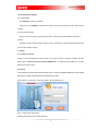
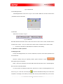
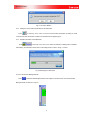
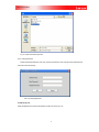
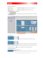
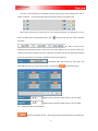
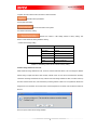
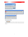
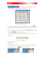
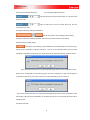
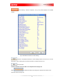
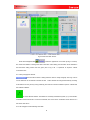
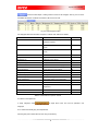
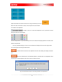
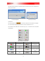
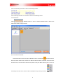
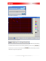
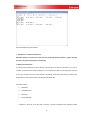
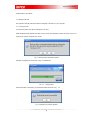
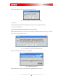
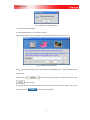
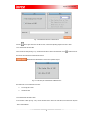
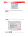
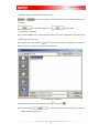
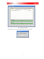
User’s Manual
For
Imposa Tools software
Version:
:2.06
Imposa Tools software
Revision History
Revision
Date of Revision
Description
Revised by
1.0
2006-11-24
This is the first edition.
Sureone
1.1
2006-12-18
Modified support connection address.
Sureone
1.2
2006-12-26
Updated the Imposa Tools software.
Sureone
2.06
2007-11-5
Updated the Imposa Tools software, version is
2.06.
1
Lin Zhenyu
Imposa Tools software
Table of Contents
1.
.TERMS AND DEFINITIONS ....................................................................................................................... 1
2.
.INTRODUCTION TO THE FUNCTIONS OF THE SOFTWARE ................................................................. 1
3.
.OPERATION ENVIRONMENT ................................................................................................................... 1
3.1 System Requirements ............................................................................................................................ 1
3.2 Connecting the Equipment ..................................................................................................................... 2
4.
.STARTUP ................................................................................................................................................... 2
4.1 Preparing for startup ............................................................................................................................ 2
4.2 Startup ................................................................................................................................................... 2
5.
.INTRODUCTION TO THE SOFTWARE INTERFACE ............................................................................... 3
5.1 Interface Introduction of the Imposa Tools .............................................................................................. 3
5.2 Menu Bar ................................................................................................................................................ 3
5.3 Setting Bar .............................................................................................................................................. 5
5.4 LDU Management Bar ............................................................................................................................ 6
5.5 Status Bar ............................................................................................................................................... 6
6.
.EXPLANATIONS ON BASIC OPERATIONS ............................................................................................. 6
6.1 Managing the LDU .................................................................................................................................. 6
6.2 Saving or Opening a Project File .......................................................................................................... 10
6.3 Adjusting Time ...................................................................................................................................... 11
6.4 Testing the Serial Ports ......................................................................................................................... 12
6.5 Setting the Parameters for the LDU...................................................................................................... 14
6.6 Setting the Parameters of the Screen................................................................................................... 18
6.7 Basic Information of the LDU, Basic Color Adjustment and Display Test ............................................. 24
6.8 Equipment Test ..................................................................................................................................... 30
7.
.EXPLANATIONS ON ADVANCED OPERATIONS .................................................................................. 33
7.1 Backup and Restoration ....................................................................................................................... 33
7.1.1 Backup LDU data............................................................................................................................... 34
7.1.2 Recover ............................................................................................................................................. 36
7.1.3 Backup Config Files for All Display Tiles............................................................................................ 38
7.2 Repair and Upgrading........................................................................................................................... 39
7.2.1 Upgrading software............................................................................................................................ 40
7.2.2 Read back the data............................................................................................................................ 41
7.2.2 Repairing ........................................................................................................................................... 43
7.3 Guide to Repairing ................................................................................................................................ 44
2
Imposa Tools software
1.
.Terms and Definitions
VPU3000:Video Process Unit
LDU3000:LED Distribute Unit
Imposa ® cabinet: The exterior dimensions of the cabinet are fixed. Each cabinet is matched with 6
display modules. Each module has various rows and columns of pixels that make up the resolution,
while the pixels are situated at certain distances which we call Pitches. Different pitches lead to
different specifications.
Display module:The modules are made up of light emitting diodes, driving circuits and front masks.
The modules are potted with high performance silicon. The module is the basic element of an LED
display.
2.
.Introduction to the Functions of the Software
2.1
To detect and set the size, display mode, driver board type, and color temperature, etc. of the LED
display.
2.2
To detect the status of various Imposa™ cabinets.
2.3
To test the LED display.
2.4
To read back, upgrade and repair the data on firmware, GAMMA data, configuration files, data for driver
boards.
2.5
Advanced hardware backup and restoration.
2.6
To test system communication and computer serial ports.
3.
.Operation Environment
3.1 System Requirements
Intel Pentium or Celeron MAX 500 MHz CPU or higher or compatible system
RAM:128 M or more
Available USB port or serial port (RS232)
10/100M Ethernet
CD-ROM drive
Windows 2000, windows XP and windows 2003 operate system
Displaying mode: 1024X768, 24 Byte at least
1
Imposa Tools software
3.2 Connecting the Equipment
3.2.1 Offline Display
LDU, Imposa™ cabinets, light sensor
Unless one or more Imposa™ cabinets are connected, some of the functions may not be able to perform
normally.
3.2.2 Synchronous Display
When in synchronous mode, the following equipment or instruments should be added to avail normal
operation
VPU3000, one pair of optic converters, video source (e.g., DVD player or other video equipment), DVI input
(as computers have DVI outputs)
4.
.Startup
4.1 Preparing for startup
Properly connect the equipment and the computer. If you want to connect a computer via USB to the VPU,
please refer to “Universal converter winxp A3 20060901.pdf”, and install the driver software for converting
USB to serial communication.
4.2 Startup
Choose Start\All programs\Imposa software\Imposa Tools, or double click Imposa Tools.exe in folder System
disk directory \Program Files\Imposa\Imposa Software\Imposa Tools\.
To the software, you must log in. The Login window is as the following Fig. 4.1.
Fig. 4.1 Imposa Tools Login Window
Please input Password in the box after Password.
2
Imposa Tools software
If this box is selected, the software will remember the password you have input so
that next time when you log in, you don’t have to input the password.
To log in to the Imposa Tools software.
To exit.
After logging in, you will see the software interface as shown in the following Fig. 5.1
5.
.Introduction to the Software Interface
5.1 Interface Introduction of the Imposa Tools
After the software Imposa Tools have been started, you will see the following (See: Fig. 5.1):
Fig. 5.1 Main interface of Imposa Tools
5.2 Menu Bar
As Fig. 5.1 area 1 shows, the Menu Bar has four menus: File, View, Tool and Help.
Fig. 5.2 Menu Bar
Menu Bar supports the same shortcut operation with Windows. One can press “Alt +the first letter of the
menu name”. See Tab. 5.1.
3
Imposa Tools software
Menu Name
Shortcut key
File
Alt + F
View
Alt + V
Tool
Alt + T
Help
Alt + H
Table 5.1 Shortcut key of Menu Bar
5.2.1 File menu includes: Open Project, Save Project, Change Password and Exit.
Fig. 5.3 File menu
Save Project serves as saving the communication parameter and basic parameter on the
current project.
Open Project is to open the project file saved before.
Change Password is to modify the current user’s password.
Exit means exit from the Imposa Tools software.
5.2.2 View menu includes: Tile Information, LDU Setting, Screen Setting, Device Check, and Maintenance.
Choose different buttons to switch to different setting windows.
Fig. 5.4 View menu
5.2.3 Tool menu includes: Maintenance Wizard, Adjust Time, Serial Check, Auto Assign Address For Tiles,
Backup LDU Data, Recover, Backup Config Files of All Tiles, and Read Back All Brightness Data.
4
Imposa Tools software
Fig. 5.5 Tool menu
♦
Maintenance Wizard: Maintenance guide for operation.
♦
Adjust Time: To adjust the time of the display.
♦
Serial Check: Serial port for check.
♦
Auto Assign Address For Tiles: Automatically assign the address of each Imposa cabinet
♦
Backup LDU Data: For Backup of LDU data.
♦
Recover: To recover LDU data.
♦
Backup Config. Files of All Tiles: For backup of config files of all tiles.
♦
Read Back All Brightness Data: read back the brightness data of each cabinet.
5.2.4 Help menu only comprise About.
Fig. 5.6 Help menu
Select ”Help\About”, and the instructions to the software edition will appear ,see Fig. 5.7. Click
anywhere on the window to exit the window.
Fig. 5.7 About window
5.3 Setting Bar
Area 2 in Fig. 5.1 is just the Setting Bar. Select different buttons to switch to different setting windows.
The functions are the same with View.
Setting window is in area 4 in Fig. 5.1.
5
Imposa Tools software
Fig. 5.8 Imposa Tools
5.4 LDU Management Bar
LDU Management Bar is in the area 3 in Fig. 5.1. One can add or delete LDU, set LDU’s communication
parameters and even refresh them.
Fig. 5.9 LDU Management Bar
5.5 Status Bar
Status Bar is in the area 5 in Fig. 5.1.
Fig. 5.10 Status Bar
Status Bar illustrates the firmware version of LDU. CPU Version is CPU’s version number, and FPGA Version
is FPGA’ version number.
♦
In Fig. 5.10, CPU’s version number is A201, and FPGA’ version number is 9003.
The window is refreshed only after Status Bar is switched to Screen Setting.
6.
.Explanations on Basic Operations
6.1 Managing the LDU
Through LDU Management Bar, one can add or delete LDU, set LDU’s communication parameters and
even refresh them.
Whenever switching among the operating windows, please remember to press
before performing the next operation.
NOTE: 1 LDU can be consisted by many LDU HUB. Please note that what is shown in LDU Management
Bar is the LDU corresponding address.
If it is the first time to operate the Imposa Tools, there will be no LDU in LDU Management Bar, as is
shown in Fig. 6.1. In this case, one should press
to add the LDU HUBs according to the actual screen
composition. One display can be made up of several LDUs, but they should be added one by one at a time,
6
Imposa Tools software
and can not be added all at once.
Fig. 6.1 LDU Management Bar when Imposa Tools is operated for the first time.
6.1.1 Add LDU
Press
and there will appear a window as Fig. 6.2. Set the communication parameters according to
the actual connection of LDU.
Fig. 6.2
Communication parameter setting for LDU
When computer and LDU communicate with each other via RS232/485 or VPU, choose RS232/485 and
select the correct serial port and baud rate in Com Port. See Fig. 6.3.
PIC 6.3 Selects serial port and the related baud rate.
When computer and LDU communicate with each other via Ethernet, choose Ethernet and input the
connect IP address (169.254.10.49, for example) in IP bar. See Fig. 6.4.
7
Imposa Tools software
PIC 6.4 Selecting Ethernet and input IP address
Note: If it is an off-line display, one can choose RS232,RS485 or Ethernet as the communication means
between computer and LDU. For baud rate can range from 2400Bps to 115200Bps.
When used as a
synchronous display, the communication between computer and LDU is realized by an optic fiber cable.
In
this case, only USB (USB switch to RS232) or RS232 can be used. The baud rate will be switched to
19200Bps automatically.
For the HUB Address, the option varies from F0 to F7. Set it according to the LDU’s actual connections.
Fig. 6.5 Select LDU Address
Press
to finish adding an LDU. Then the LDU Management Bar will turn to the following
window. For the newly added LDU, the address is F0, serial port is COM5, and baud rate is 19200Bps.
Fig. 6.6 Adding one LDU
6.1.2 Delete an LDU
Press
to delete a LDU, as shown in Fig. 6.7, a confirmation window will appear. Press
to delete it, or
to cancel the operation.
8
Imposa Tools software
Fig. 6.7 To confirm deletion
6.1.3
Setting the communication parameters for the added LDU
Press
to have Fig. 6.2 to come out. Set the communication parameters according to actual
connections of LDU. Double click a certain LDU and there will also appear Fig. 6.2.
6.1.4
Rrefresh information of the added LDU
Press
to have Fig. 6.8 to come out. It means the software is reading LDU’s information.
After reading, the information will be shown in the setting window in area 4, as Fig. 5.1 shows.
Fig. 6.8 Reading LDU’s information
6.1.5 To minimize LDU Management Bar
Press
to Minimize LDU Management Bar. Press it again to resume full size. The minimized LDU
Management Bar is shown as in Fig. 6.9.
9
Imposa Tools software
Fig. 6.9 Minimized LDU Management Bar
6.2 Saving or Opening a Project File
6.2.1 Save the current project file Select File\Save Project to a file, Project1, for example, and press Save. The
suffix is cpj.
Fig. 6.10 Name the project file
6.2.2 To open a saved project file
Select File\Open Project. Choose the file—Project 1.Click Open. The extension suffix of the project file is
cpi.
10
Imposa Tools software
Fig. 6.11 Open the saved Project file.
6.2.3. Change Password
Select File\Change Password. First of all, input the old password. Then input the name password twice.
Click OK to finish the change.
FIG 6.12 Change password
6.3 Adjusting Time
Select Tool\Adjust time, and there will appear a window as shown Fig. 6.12.
11
Imposa Tools software
Fig. 6.12 Window of adjusting time
The software will read the date, time and time zone of the connected LDU, and show them in the Display
bar. The date, time and zone of the computer will be shown in the Computer bar.
Read the date, time and time zone of the connected LDU, and show them in the Display
bar.
Adjust time. Send the computer’s date, time and time zone to the connected LDU. If the
adjusting is successful, a window as shown in Fig. 6.13 will appear. Or if failed a failure prompt will come out.
Fig. 6.13 Time adjusted successfully.
Close the current window
6.4 Testing the Serial Ports
Select Tool\Serial Check to have Fig. 6.14 to come out. This test can check if the serial port of the
computer is normal. Before the test, connect the red joint attached with LDU to the serial port that needs
testing.
Prepare the universal adaptor switching USB to RS232 to check USB port.
12
Imposa Tools software
Fig. 6.14 Window of Checking a Serial Port
6.4.1 Select a serial port and set its parameters
Choose the serial port to be tested.
Set the baud rate of the serial port to be tested.
6.4.2 Starting and finishing testing
After selecting the serial port and baud rate, press button Start to start the test. The result will
be shown in the Message window ( Fig. 6.15) of Check Serial Port ,Fig. 6.14.
Fig. 6.15 Message window of Check Serial Port
Press it to stop the test.
Delete the information in Message window.
Close the testing window.
13
Imposa Tools software
6.4.3 Meanings of the results
It means the serial port works abnormally.
It means the serial port is normal.
6.5 Setting the Parameters for the LDU
Select
or View\LDU Setting in the setting bar of Imposa Tools to switch to LDU Setting
window, See Fig. 6.16.
Fig. 6.16 LDU Setting window
6.5.1 Basic Setting
Set the X and Y coordinates of LDU. Only valid for synchronous
displays.
Set the size of the display controlled by the LDU HUB. The setting
should be on the basis of the display’s actual composition. When setting, one can press the number keys on
the keyboard directly or click
at the right of the input box to add or decrease the number.
6.5.2 Communication Setting
Set the IP address of LDU HUB when using Ethernet to
14
Imposa Tools software
communicate.
Set the baud rates of COM1 and COM2 on LDU HUB, Baud
Rate 1 should correspond with COM1, and Baud Rate 2 with COM2. The default baud rate is 115200Bps.
Set the number of Imposa™ cabinets that connected to the LDU
HUB.
6.5.3 Advanced Setting
This is the display mode of the LED sign. User can choose either
Synchronous or Asynchronous
group information of the Gamma Data of the LED sign. There
are 4 Gamma groups. These 4 groups can be valid only when the sign is under Asynchronous mode. For
Synchronous mode, these groups are invalid.
the signal of the LED sign can be either from Left to Right or
Bottom to Top.
There are Function 1 and Function 2 for option.
Set the height and width of the LED sign.
6.5.4 Brightness
There are 3 modes for the user to adjust the brightness:
Manual, Auto and Schedule.
when the sign is under Manual Adjust mode, input the
brightness percentage into the input box. Or users can press
as Fig 6.20 shows.
15
to activate the synchronous setting,
Imposa Tools software
FIG 6.20 Adjust Brightness widow
Adjust the color temperature of the display. Set it to be
6500K, 9300K or Preset. The set value will be shown on the display immediately.
Set the color temperature when at 6500K.
When setting, one can press the number keys on the keyboard directly or click
at the right of the input
box to add or decrease the number.
Set the color temperature when at 9300K.
Preset the color temperature.
Set the color temperature of the display synchronously. Press
to open the Color Adjusting Dynamical window . See Fig. 6.17.
Fig. 6.17 DynamicColor Adjusting window
16
Imposa Tools software
The value of color temperature of the display set in this window can be shown forthwith, but it can’t be
saved in config files.
One minute later after setting, the display will return to the original value.
When adjusting the ratio of the three colors so as to change the display’s color temperature, one can
press the number keys on the keyboard directly or click
at the right of the input box to add or decrease
the number
The place to save the color
temperature after setting. Press Save to 5600 to save the value to 5600K. Or you may save it to 9300 in the
same way. Press Save to Preset to save it to a Preset place. The saved value of color temperature should be
sent to LDU. Otherwise one minute later, the display will return to the original one.
Automatically switch ON and OFF the LED screen. The
default setting is OFF. If you want to use this function, click the button
to activate the function.
Please input time to power up after Power On. 24 hour system.
Please input time to power up after Power On. 24 hour system.
6.5.5
Sending and resuming the parameter.
Send the set parameter to LDU.
After sending, LDU will be reset automatically. Therefore, the
17
Imposa Tools software
computer will hault communication with LDU for several seconds.
Read back LDU’s parameters.
6.5.6 System Information
Show the information of the system
6.5.7 Restore to Factory Setting
Recover the content in LDU Setting window to factory setting. This
doesn’t include: Advanced setting and Basic Setting.
Contents of the factory setting.
Item
Value
Communication
Color Adjust
IP
169.254.10.49
Baud rate1
115200
Baud rate2
115200
6500K
R:100 G:100 B:100
9300K
R:100 G:100 B:100
Preset
R:100 G:100 B:100
TABLE 6.1 LDU Setting window for the content of factory setting
6.6 Auto Assign Address for the Tiles
Select Tool\Auto Assign Address for Tiles, as FIG 6.18 shows. With this feature, user can assign the address
without having to adjust the switch code manually. Instead, users can use CPU to download the necessary
information and assign the address of every cabinet. Press Auto Assign Address for Tiles, a window shows-up
as FIG 6.18 shows. Press Yes, users will see the processing window of FIG 6.19. The system will reboot if the
assignment is not successful, as FIG 6.20 shows. If the Assignment is successful, user will see the window of
FIG 6.21.
FIG 6.18 Inquire window of auto assign address
18
Imposa Tools software
FIG 6.19 Processing window of auto assign
FIG 6.20 Power up (reboot) again to display when assignment is failed
FIG 6.20 Successful auto assignment
Setting the Parameters of the Screen
Select
or View\Screen Setting in the setting bar of Imposa Tools to switch to Screen
Setting window, see Fig. 6.18. Just as Fig. 6.19 shows, the software can read back the display’s parameters
automatically.
19
Imposa Tools software
Fig. 6.18 Screen Setting window
Fig. 6.19 Software read back the display’s parameters automatically after entering Screen Setting
6.6.1 Type
Show cabinet’s type. This value is read back automatically by the
software.
Set the width and height of the display according to the display’s
exact size.
6.6.2 Display
The displaying mode of the display. There are two options:
20
Imposa Tools software
Synchronous or Asynchronous
The gray mode of the display. Two options: 5:6:5 or 8:8:8. This can
only be valid when the display is in the mode of off-line displaying.
Gamma Index of the display. Altogether there are 4 groups: 1—4.
This function is valid only when the display is in the mode of off-line displaying.
6.6.3 Brightness
Set the brightness control mode of the display. There are three
modes: Manual, Auto and Schedule.
Brightness setting when the mode is Manual. One can select a
value directly in the input the box or press
to set it synchronously.
The synchronous setting
window is shown as Fig. 6.20 .
Fig. 6.20 Adjust Brightness window
Click the triangle button
or input the needed value directly into the box. The display will reflect the related brightness immediately.
Press
to close the window and save the value to the input box following Manual
Adjust. Press
to close the window without saving.
♪ It is only valid after sending it to LDU. Or one minute later, the display will recover to the original value.
6.6.4 Brightness schedule setting
21
Imposa Tools software
Schedule the brightness of a whole day manually. It is unvalid
when the brightness schedule is default. The window is as Fig. 6.21 shows.
Fig. 6.21 Brightness Schedule window
The schedule can be divided to 10 period of time maximum. As Fig. 6.22 shows, only after ticking
in the
box at the front of the schedule bar it can be valid. Input the start time into the Start Time box, end time into the
End Time box, and brightness value into the Brightness box. Press
window. Press
to save and close the
to close the window without saving.
It divide a day into two phases, one is from 8:00 to 17:00. The other is from 17:01 to 07:59. Both of their
brightness is 100%.
Fig. 6.22
One schedule bar
The schedule time is 24hour mode.
6.6.4 Power ON/OFF
Open or close the display according to the pre-set schedule time. When it is default, it on the function of OFF.
So for the usage of this function, click
to start the function. See Fig. 6.23b.
22
Imposa Tools software
PIC 6.22a Power ON/OFF being OFF
PIC 6.22b Power ON/OFF being ON
Input the start time into the box behind Power On. The time should
be 24 hour mode.
Input the close time into the box behind Power Off. The time
should be 24 hour mode.
6.6.5 Restore to Factory Setting and Read Back
Recover the content in Screen Setting window to factory
setting and read back the display’s parameter. This function is the same with that in LDU Setting.
6.6.6 Smart Send in Screen Setting
Press Send in Screen Setting, and the software will check automatically if there are files going
with the current configuration in LDU and make hints.
There is no such LDU FPGA files in LDU, then there
will appear a confirmation window as Fig. 6.23 shows. Press Yes to continue the sending, and No to cancel it.
Fig. 6.23 Hint window when there is no LDU FPGA files that go with the current configuration in LDU
When there is no FPGA files of control board going with the current configuration in LDU, there will appear a
confirmation window as Fig. 6.24 shows. Press Yes to continue the sending, and No to cancel it.
Fig. 6.24 Hint window when there is no control board FPGA files that go with the current configuration in LDU
After sending, LDU will recover automatically. So computer and LDU will not communicate with each other for
several seconds.
6.6.6 More information
23
Imposa Tools software
After selecting, a window will appear ( as Fig. 6.25). What displayed is the detailed
contents.
Fig. 6.25 Detailed information for Screen Settings
Contents in the detailed information for Screen Settings window can be sent to a LOG. file.
Press Export , select a saving path and name the saved file. The suffix of the file is LOG.
Close the window.
6.7 Basic Information of the LDU, Basic Colors Adjustment and Display Test
Select
or View\Tile Information in the setting bar of Imposa Tools to switch to Tile
Information window. See Fig. 6.26.
24
Imposa Tools software
Fig. 6.26 Tile Information window
Press LDU Management Bar
to make the appearance of a window (as Fig. 6.8 shows).
This means the software is reading back LDU’s information. After reading, the information will be reflected in
Tile Information setting window. See the green pane in Fig. 6.26.
It represents an Imposa™ cabinet
connected to LDU.
6.7.1 Outlay viewgraph of cabinets
Click the button Position in setting window to switch to outlay viewgraph. From Fig. 6.26 we
can see that there are 25 cabinets connected to LDU.
These cabinets are arranged automatically according
to the data flow. So they are only having something to do with the connection between Imposa™ cabinets and
LDU instead of address.
08 is the cabinet’s address. The address is counted by hexadecimal system. (0,1) is the cabinet’s
coordinates in the whole screen. 0 is the line coordinate, and 1 is the column coordinate. So the cabinet is in 0
line and the first column.
6.7.2 List viewgraph and the reflecting information
25
Imposa Tools software
Click the button Report in setting window to switch to list viewgraph. See Fig. 6.27. It shows
the detailed information of cabinets connected to LDU in the form of list.
Fig. 6.27 List viewgraph window
List viewgraph reflect the information of Imposa™ cabinets. See Table 6.2 for details.
Item
Instructions
Address
Cabinet’s
Unit
address.
Represented
by
hexadecimal system
X
X coordinate of the cabinet in the whole
screen
Y
Y coordinate of the cabinet in the whole
screen
Width
Width of the cabinet
Pixel
Height
Height of the cabinet
Pixel
Brightness (%)
Brightness of the cabinet
%
Temperature (C)
Temperature of the cabinet
℃
CPU Version
Version of control board CPU program
FPGA Version
Version of control board FPGA program
Frame Frequency
Frame frequency of the cabinet
Fan (On/Off)
On /Off status of fans in cabinet
Fan Current (mA)
Working current of fans in cabinet
mA
Power Voltage1 (V)
Input power voltage 1 of control board
V
Power Voltage2 (V)
Input power voltage 2 of control board
V
Ethernet State
State of
Ethernet
Time in high Temperature
Working
duration
of
cabinet
Hz
in
high
temperature
SN
Serial number of cabinets
Gamma Index
Gamma data index of control board
TABLE 6.2 Information for Imposa™ cabinet
6.7.3 Basic colors adjustment
In outlay viewgraph, select
to adjust basic colors. This can’t be operated in List
viewgraph.
6.7.3.1 Select the cabinet going to be adjusted first
Click the green pane under Position of Tiles using mouse left key.
26
Imposa Tools software
When more than one cabinet is chosen, users can press Ctrl and click the cabinets.
to open the selecting window. See Fig. 6.28.
Or one can click
Fig. 6.28 Cabinet selecting window
Available Tile(s):
Address of the cabinets that are available.
Selected Tile(s): Address of the selected cabinets.
The selecting and deleting of cabinets are operated by the following buttons in the table.
Button
Instructions
Select one cabinet’s address in Available Tile(s) and press this button to add it to Selected
Tile(s).
Add all the cabinets in Available Tile(s) to Selected Tile(s).
Delete the selected cabinets in Selected Tile(s).
Delete all the cabinets in Selected Tile(s).
TABLE 6.3Iinstructions for buttons
Reflect the selected cabinets to Position of Tiles and close the window.
Close the window
If ticked in the box, then all the cabinets in Position of Tiles will be selected.
6.7.3.2 Select modules in the selected cabinet
Adjust the whole cabinet
27
Imposa Tools software
Adjust the modules in the cabinet. Click one box using mouse left key to turn it to
,
When more than one module is chosen, users can press Ctrl and click them.
6.7.3.3 Basic color adjustment
If ticked in the box, it means the adjustment can be synchronous and the
display will reflect the result forthwith.
Click the triangle button or input values directly into the box. Observe the displaying effect of the screen until it
meets the requirements.
♪ It is only valid after sending it to LDU. Or one minute later, the display will recover to the original value.
6.7.3.3 Sending and recovering the default value
Send the result of the basic color adjustment to LDU. After sending, the display will show it
ourt.
Recover the default value of the selected cabinets or module’s basic color adjustment. When
the following hint window appears, press Yes to continue and No to cancel it.
Fig. 6.29 Confirmation window for recovering the basic color adjustment
28
Imposa Tools software
The operation will take a longer time, so be patient. When the hint window as shown in Fig. 6.30b appears, the
recovery will be successful.
PIC 6.30a Sending Data
PIC 6.30b Set successfully.
6.7.4 Basic test
to have Basic test. Basic test can’t be operated in list viewgraph.
In the outlay viewgraph, select
6.7.4.1 Select cabinets need operating before Basic test. The way is the same with 6.1.7.3.1.
6.7.4.2 Select the mode of Basic Test in the mode box (Fig. 6.31) . For instructions of each mode please
consult TABLE 6.4.
Fig. 6.31 Mode window of Basic test
Mode button
Instructions
Mode button
Instructions
Scan in vertical lines from
The whole display is red.
left to right
The whole display is
Black screen. No display
green
of the selected cabinets
Show the switch on
The whole display is blue
Information of selected
cabinets
The whole display is
Test automatically
white
29
Imposa Tools software
Scan in lines from bottom
Stop test
to top
TABLE 6.4 Instructions for the mode of Basic test
6.8 Equipment Test
Test the state of the connected equipments. Select
or View\Device Check
The setting bar of Imposa Tools to switch to Device Check window. See Fig. 6.32.
Fig. 6.32 Device Check window
Start Device Check. The testing result will be shown in Message window. The software will
test the status of LDU and cabinets automatically. See Fig. 6.33a and Fig. 6.33b.
Stop Device Check.
Send the testing result to a LOG file. Click Export and name the file then save it. The suffix of
the sent Device Check result is LOG.
If ticked in the box, Message window will show only wrong information.
30
Imposa Tools software
PIC 6.33a LDU testing information in Device Check Message window
PIC 6.33b Testing information of control board in Device Check Message window
6.9 Pixel detection
Select
in IMPOSA TOOLS. Or users can choose View\Pixel Check to switch to the
Pixels Check window, as Fig 6.33 shows.
FIG 6.33 Pixels Check Window
Press Pixel Check in FIG 6.33 to open the detection function. Or double-click
, as FIG 6.34 shows.
When the process reaches 100%, there will be no difference with the interface. Click Detail, as FIG 6.35 shows.
With this function, user will be able to see the exact position of each pixel. Black means the pixel is normal. For
the meaning of the other colors, users can refer to the table on the right, as Fig 6.35 shows.
31
.
Imposa Tools software
FIG 6.34Open the pixel detection
FIG 6.35 the exact position of each pixel
Tile Address refers to the address of
the cabinet that with the problem pixel. In this drawing, the address is 00. User can clink
there will come out a .txt file, as FIG 6.36 shows. Click
48X64 refers to the type of the Imposa cabinet.
32
,
for a second checking. In FIG 6.36,
Imposa Tools software
FIG 6.36 Notepad of the pixel detection
7.
.Explanations on Advanced Operations
Advanced operation is reserved for those who have knowledge about the Imposa™ system. Improper
operation may cause abnormalities on the display.
7.1 Backup and Restoration
It is highly recommended that you save a backup of the key data in the LDU at a safe place in your LDU or
computer, so that when some accident happens, you can restore the key data from that safe place in the LDU
or from your computer to the LDU. After restoration, the settings in the LDU will be exactly the same as the
backup data. This will save the trouble of re-setting the parameter data.
Contents for backup:
♦
FPGA data
♦
Configuration files
♦
Driven files
♦
Gamma data files
♪ Operation is done only to the LDU that is currently in the LDU management bar. Operation towards
33
Imposa Tools software
multiple LDUs is not possible.
7.1.1 Backup LDU data
This operation saves key data in the LDU to a safe place in the LDU or to your computer.
7.1.1.1 Saving to LDU
To save the key data in the LDU to a safe place in the LDU.
Select Tool\Backup LDU date\Save to LDU, and you will see the confirmation window as shown in Fig.ure 7.1.
Press Yes to continue, and press No to cancel.
Fig. 7.1 Saving to LDU confirmation window
Operation in progress (as can be seen in Fig. 7.2). Please wait.
Fig. 7.2
Saving to LDU
After the operation is successful, you will see the window as shown in Fig.
Fig. 7.3 Prompt for successful operation
34
7.3.
Imposa Tools software
7.1.1.2 Saving to Computer
To save key data in LDU to a designated place in your computer.
Select Tool\Backup LDU date\Save to Computer, you will see the window as shown in Fig. 7.4.
Fig. 7.4 Backup Data window
Please press
to select the place for saving the backup files. And then name the file with the suffix LDU.
Press the button
to save the backup file to the computer, and press the button
to exit backup operation.
The progress of saving a backup file from the LDU to a computer is shown in Fig.ure 7.5. You can press the
button
anytime during the process to cancel the backup operation.
Fig. 7.5 Backup Progress window
35
Imposa Tools software
When the operation is successful, you will see the window Fig. 7.6.
Fig. 7.6 Prompt window for successful backup operation
7.1.2 Recover
To recover the backup data from the safe place in the LDU or from your computer to the LDU.
7.1.2.1 Recovering from LDU
To recover the backup data from the safe place in the LDU to the LDU.
Select Tool\Recover\Recover From LDU, and you will see the confirmation window as shown in Fig.7.7. Press
Yes to continue, and press No to cancel.
Fig. 7.7 Confirmation window for Recovering From LDU
Operation in progress(as shown in Fig. 7.8). Please wait.
Fig. 7.8 Recovering From LDU
When operation is successful, you will see the following window as shown in Fig. 7.9.
36
Imposa Tools software
Fig. 7.9 Prompt for successful operation.
7.1.2.2 Recovering from Computer
To recover backup data from your computer to the LDU.
Select Tool\Recover\Recover From Computer, and you will see the window as shown in Fig. 7.10.
Fig. 7.10 Window showing restoring
Press
to select a backup file in your computer with a name like Backup.LDU.
LDU backup files all have
the suffix .LDU.
Press the button
to start recovering backup files from computer to the LDU. Press
to exit recovering.
The progress window of recovering a backup file from the computer to the LDU is as shown in Fig.7.11.You
may press the button
to cancel the backup operation.
37
Imposa Tools software
Fig. 7.11 Recovering From Computer
When the operation is successful, you will see the Fig. 7.12 window.
Fig. 7.12 Prompt for successful operation
7.1.3 Backup Config Files for All Display Tiles
This is to save all configuration files to the LDU.
Select Tool\ Backup Config Files for All Tiles, and you will see the window as shown in Fig. 7.13. Press Yes to
continue and No to cancel.
Fig. 7.13 Backup Config Files for All tiles
Operation in progress (as shown in Fig. 7.14). Please wait.
38
Imposa Tools software
Fig. 7.14 Backup Config Files for All Tiles in progress.
After the operation is successful, you will see the window as shown in Fig. 7.15.
Fig. 7.15 Window for successful operation
7.1.4 Read Back All Bright Data
Read back all the brightness data of all cabinets
Select Tool\Read Back All Bright Data. The following window will shows up.
FIG 7.16 Read Back being read
7.2 Repair and Upgrading
It can repair or upgrade the data in the control card or LDU, and read back various data in the control card, all
39
Imposa Tools software
the data and Configuration File in LDU.
or View\Maintenance to switch to Maintenance as
In Imposa Tools column, choose
Fig. 7.16.
Fig. 7.16 Maintenance
User can switch to different setting windows by clicking Update,
Read Back or Restore.
7.2.1 Upgrading software
Click
and switch to the window of Update as Fig.7.17.
LDU or control card through the window of Update.
40
All the required files can be sent to the
Imposa Tools software
Fig. 7.17 The window of Update in Maintenance
Click
behind the File name to choose the files which need to be upgraded. For example:
SCHFQS40_V01.RBF, the information of the file will appear in Update file information area. Like Fig. 7.18, this
is a FPGA for LDU file, its Version is 01, Modification Time is 2006-11-22 11:47:37, File Size is 72.27KB.
Fig. 7.18 Window of information for an Update file
Only when upgrading the files in the control card, can Tile Address and All Tiles be selected, when upgrading
LDU file, those two can not be selected as Fig. 7.19a and b.
Fig. 7.19a Tile Address cannot be selected
Fig. 7.19a All Tiles can not be selected
when upgrading the control card files, please choose the address of the control
card which need to be upgraded. FF means choosing all control cards.
Choosing All Tiles is equal to choosing FF address, it means choosing all control cards.
Update the open files to LDU or the selected control card.
7.2.2 Read back the data
Click
and switch to Read Back as Fig.7.20. Various data in the control card, the Configuration
Files and all data in LDU can be read back.
41
Imposa Tools software
Fig. 7.20 Read Back window in Maintenance
Choose
at the upper left corner of LDU or Tiles, choose the operating object to be LDU or Tiles.
7.2.2.1 Read back the LDU data.
In the window of LDU (like Fig. 7.21), choose the files which need to be read back, Click
behind Save as
and choose the route of the saved file and name it.
Read back the selected files in the chosen operation object.
Fig. 7.21 The LDU part in Read Back of Maintenance
The data which can be read back from LDU
♦
The config file of LDU
♦
All data of LDU
7.2.2.2 Read back the data of Tiles
In the window of Tiles (As Fig. 7.22), choose the files which need to be read back, and choose the required
Tiles in Tiles Address.
42
Imposa Tools software
Fig. 7.22 The part of Tiles in Read Back of Maintenance
Click
behind Save as and choose the route of the file which need to be saved, and name the file.
Read back the selected files in the chosen item for operation.
The data which can be read back from Tiles
♦
The config file of Tiles
♦
The Gamma data of Tile
♦
FPGA data of Tile
♦
Drive plate date
7.2.2 Repairing
Click
and switch to the window of Restore as Fig.7.23. The Repairing operation is valid only to
Tile.
Fig. 7.23 Window of Restore in Maintenance
choose the address of the Tile which needs to be repaired, FF means
43
Imposa Tools software
choosing all control cards.
Choosing this is equal to choosing FF address, it means choosing all control cards
Selection in Operation mode
The repairing work begins in the selected object for operation.
The operation mode of Tiles
♪
♦
The config file of Tiles
♦
Restore the FPGA of Tile
♦
Restore the Gamma data of Tile
♦
Restore the Drive board data
♦
Restore the config file of Tile
♦
Restore single Tile
Restore single Tile does not support the simultaneous operation to more than one Tile.
7.3 Guide to Repairing
Select the Tool\Maintenance, and the Guide will read back the configurations automatically as shown in
Fig.7.24. The repair interface is as shown in the following Fig.7.25
Fig. 7.24
Guide reading back the configuration parameters
44
Imposa Tools software
Fig. 7.25 Interface of repairing
7. 3.1 Introduction to the interface
Show cabinet’s type. This value is read back automatically by
the software.
items. Repairable items are listed under the Program.
The repairable items:
Configure of LDU:
LDU configuration files
FPGA For LDU(0000):
LDU’s FPGA files
Configure of Tiles:
Cabinet configuration files
FPGA For Tiles(0000):
Drive Board Data:
Gamma Data:
Cabinet configuration files
Cabinet driver board data table
Gamma data
To select a file that corresponds to a repairable item
and
indicate the status of the repairable items. The Computer column indicates the
status of the items in the computer; the LDU column indicates the status of the items in the LDU. Exist means
45
Imposa Tools software
that the item exists; Not Exist means that it does not exist.
and
refer to the operation to the items. Restore means to restore and Update means
to upgrade.
is to execute the operation, and
to exit the Guide.
7. 3.2 Introduction to operation
Step 1: Select Tool\Maintenance, and the Guide will read back the screen configurations. The interface of the
repairing is as shown in Fig.7.25
Step 2: Select a file. Click the button
after Configure of LDU. Select the desired file in a window as
shown in Fig.7.26, say Config file of LDU.ini, and then click Open.
Fig. 7.26 Selecting a desired file
Step 3: Select an operation. Under Update, click the box
Step 4: Press the button
so that it shows
.
to run the operation you have selected, and you will see the
window as shown in the Fig.7.27.
46
Imposa Tools software
Fig. 7.27 Update Progress window
After the operation is over, you will see the window as shown in Fig.7.28. Press OK to exit.
Fig. 7.28 Window showing Updated successfully
47