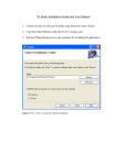
1
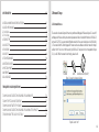
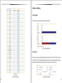
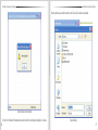
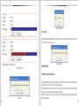
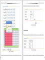
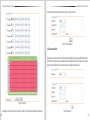
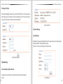
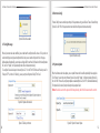
High-definition Network Cameras
ANSON
Address: (HK)
4F, BlockTechnology
5, Wuzi IndustrialCo.,
Park,LTD.
Fada
Road,
Bantian, Longgang District, Shenzhen, China
Shenzhen Enerson Technology
E-Mail:
www.i cctv-ax.
C
o info@cctv-ax.
m p a nnet y Website:
L i m
t e comd
High-definition
Network Cameras
Address: 4F, Block 5, Wuzi
Industrial Park, Fada Road,
Bantian, Longgang District,
Shenzhen, China
E-Mail: info@cctv-ax. net
Website: www. cctv-ax. com
compress bigger and clearer image because of faster digital processor. Its smoother transfer and clearer display
because of advanced OS and audio. Its reliable and stable running depend on embedded server, out of PC, high
scheduling efficiency, curing code in the flash. Accessing it by IE browser. Two-way voice intercom, dynamic IP
address and transfer image and audio conveniently are available.
FEATURE:
Introduction
V1.0.0
Megapixel IP Camera is an embedded and 38*38 HD surveillance device designed for compressing and processing
audio and video data. It consists of audio and video compressing encoder, IO channel, network interface, audio
and video interface, RS422 serial interface, protocols interface and software interface. It also can process video,
which mainly responsible for capturing image data, compressing H.264 image data, process data transmitted
on internet and audio and video data, transmit real-time image and audio at the same time on network. It can
Two video and audio is independent, 60 frame activity video per second
H.264 video compression standard
Embedded WEB server and surveillance, configure, update by IE
Transfer two-way audio on internet; adjust frame rate according bandwidth automatically
Variable Bit rate, it can limit compressing stream of image while the image is fixed.
Two domains, dynamic IP or ADSL is easily
Bit rate range from 64 kbps to 4 Mbps, frame rate range 1 to 25 (30)
Capture picture and local record is available.
Motion detect alarm is available by setting checking area and Sensitivity
Prerecord while alarm is available
10/100 M Ethernet
IO interface connects external device is available
RS485 interface connect network transparent channel, control transparent channel of Megapixel IP Camera by client
Multi-user simultaneous accessing is available
Input and output alarm message is available
PC configuration: CPU 3.0GHZ; memory 1G; 128M graphics card; 2.1 sound card; audio output; Mic input,
windows 2000/XP/2003/Vista/7, IE6.0-8.0.
There may be technical inaccuracies and typographical errors in the manual. Products, updated in real time,
the contents of the manual will be updated from time to time without prior notice. The updated content will be
added in new version. If there is difference between manual and products, all product-based.
CONTENT
1 NETWORK SETUP
1
1.1 NETWORK STATUS
1.2 ETHERNET SETUP
1.3 WIFI SETUP
1.4 ADSL SETUP
1.5 DDNS SETUP
1.6 UPNP SETUP
1.7 FTP ACCOUNT
1.8 SMTP ACCOUNT SETUP
1.9 STREAM SETUP
1.10 PLATFORM SETUP
1
4
5
7
7
8
9
9
10
11
2 MEDIA SETUP
12
2.1 PLAY VIDEO
2.2 VIDEO CAPTURE
2.3 TIME AND TITLE SETUP
2.4 VIDEO ENCODE
2.5 PICTURE CAPTURE
2.6 AUDIO CAPTURE
2.7 AUDIO ENCODE
12
15
17
18
19
19
20
3 PTZ SETUP
21
3.1 PTZ BASIC
3.2 PTZ ADVANCED
21
21
4 RECORD AND REPLAY
23
4.1 STORAGE INFO
4.2 PLAY BACK
4.3 RECORD SETUP
4.3.1 Basic Setup
4.3.2 Motion Detect Alarm Record
4.3.3 Motion Detect Alarm Capture
4.3.4 IO Alarm Record
4.3.5 IO Alarm Picture Capture
4.3.6 Schedule Record
4.4 STORAGE MANAGE
4.4.1 Unmount
4.4.2 Format
23
23
28
28
28
29
30
31
32
33
33
35
5 ALARM SETUP
35
5.1 MOTION DETECT ALARM SETUP
5.2 IO INPUT ALARM
5.3 VIDEO LOST ALARM
5.4 STORAGE FULL ALARM
35
39
41
42
6 SYSTEM SETUP
42
6.1 SERIAL NUMBER AND KERNEL VERSION
6.2 ACCOUNT MANAGE
6.2.1 Add, Delete
6.2.2 User Group
6.3 TIME SETUP
6.4 LOG SETUP
6.5 LOG VIEW
6.6 LOG FILE
6.7 CONFIG MANAGE
6.8 RESTORE CONFIG
6.9 SYSTEM UPDATE
6.10 REBOOT
6.11 LANGUAGE
42
43
43
44
46
47
48
49
50
51
51
54
54
7 FREQUENTLY ASKED QUESTIONS
54
7.1 WHY CAN NOT ACCESS THE MEGAPIXEL IP CAMERA BY IE?
7.2 WHY THE PTZ CAN NOT CONTROL?
7.3 WHY CAN NOT SWITCH THE DATA?
7.4 WHY CAN NOT ACCESS THE MEGAPIXEL IP CAMERA AFTER UPDATE?
7.5 NO SOUND AFTER CLICK “VOICE TALK”
54
55
55
55
55
1 Network Setup
1.1 Network Status
The connection schematic diagram for the entire system frame of Megapixel IP Camera as figure 1.1. Connect PC
and Megapixel IP Camera directly and set network parameter as follow: 1. the default IP address is 192.168.0.123,
net mask is 255.255.255.0, so you must add a IP address make the PC can access the device (such as 192.168.0.88).
2. The net mask of the PC and the Megapixel IP Camera must be same. Make sure the direct network is through,
as follow: “Start”-“Run”-enter “cmd” then enter “ping 192.168.0.123” and press “enter” on the keyboard. As figure
1.3, 1.4, and1.5. While the network is not through, please check it.
TS38ABFG
Switch
Surveillance Client(Static IP)
Figure1.1 connecting schematic diagram
Figure1.2 enter “cmd”
01
HD Network Camera User’s Manual
Figure 1.5 networks is not through
02
Fiure1.3 enter “ping 192.168.0.123-t”
After then, power on. Enter the IP address in IE browser and press “enter”. Then it will display the following interface
as figure1.6, and then enter user name (admin) and password (123456) and click “Login”.
Figure1.4 network is through
Figure 1.6 Login interface
03
HD Network Camera User’s Manual
HD Network Camera User’s Manual
After enter system select and click “Network Setup”, it will display interface as figure 1.7, displaying the IP address,
gateway, net mask and DNS and so on. The detail information please refers to the actual configuration.
Figure 1.7 Network status
1.2 Ethernet Setup
Ethernet setup as figure 1.8, all the parameter in the interface is needed to be reset. Also you can modify the IP
address by IP search (carried with UC2) or other tools. Make sure the IP address to be modified and IP address
of your PC are in the same network segment, and the IP address to be modified can not be the same as the IP
address of the PC in the network segment. After reset IP address the device will reboot, then use the new IP
address to access the camera.
Net mask match with IP address to distinguish network address with local address, as 255.255.255.0. the correct
net mask is the premise for saving it. Gate way is point between two networks such as router. So you can enter
the router IP address.
DNS server address is host IP address running the domain server, which provide by network operators. If enable
the DHCP then it will obtain dynamic IP.
04
Figure 1.8 Ethernet setup
1.3 WIFI Setup
WIFI setup as figure 1.9. First you need to set wireless router called AP for short. All parameters in this interface
must be the same with the router setting.
05
HD Network Camera User’s Manual
HD Network Camera User’s Manual
1.4 ADSL Setup
ADSL setup as figure 1.10
The username and password of the ADSL are provided by network operators, enter the correct username and
password, enable ADSL and save it.
It can run correctly on premise that the username, password and the confirm password is correct.
It will prompt error while the password and confirm password is incorrect. In order to verify the ADSL is run correctly,
you can enable DDNS and access the device by domain name. enable DDNS as figure 1.11 DDNS Setup)
Figure 1.10 ADSL Setup
1.5 DDNS Setup
Figure 1.9 WIFI Setup
06
DDNS setup as figure 1.11
First you must have a domain name. www.3322.org is recommended; please remember the username, password
and domain name.
Then enable DDNS, select the DDNS Server as “3322.org”. if your domain name is “test.3322.org”, please enter
“test” in the DDNS Domain, and the User Name and Password is the username and password that applied in the
www.3322.org. set the Refresh Time as 1 minute, then DDNS will work after 1 minute.
Last you can access the device by domain name.
07
HD Network Camera User’s Manual
HD Network Camera User’s Manual
1.7 FTP Account
FTP account setup as Figure1.13.
First a FTP server is indeed. Then apply a FTP account from the FTP server (username and password).
And you must create four directory as “alarm”, “log”, “set”, “update” or other directory name, also you can enter
“./” then the entire document will be save in the root of the FTP server.
The default port of FTP is 21. The information of the interface must be correct to make sure the FTP function run correct.
Alarm upload, log backup, configure backup and update can be uploaded by FTP.
Figure 1.11 DDNS Setup
1.6 UPNP Setup
Figure1.13 FTP Setup
UPNP setup as Figure1.12.
UPNP run by external address and port.
1.8 SMTP Account Setup
Figure1.12 UPNP Setup
08
SMTP account setup as figure1.14.
The SMTP function can run correctly on premise that the entire information in the interface is correct.
SMTP Server Address is the IP address of the SMIP server, the default port is 25, the authentication is enabling.
The public network mail is no available. The show account can be anything.
The user mail address can not be empty and must be efficacy.
The CC mail address can be empty or other information. But only the correct address can receive mail.
09
HD Network Camera User’s Manual
HD Network Camera User’s Manual
1.10 Platform Setup
Figure1.15 Stream Setup
Platform Setup as figure1.16.
Figure1.14 SMTP Account Setup
1.9 Stream Setup
Stream Setup as figure 1.15.
Access Protocol: while the device is in public network, TCP is a better choose, while the device and the user are
the same network then UDP is a better choose.
The default WEB port is 80. You can change it at will. But if you change it as 8080, then you enter 192.168.0.123:
8080 for accessing the device.
All the port in the interface can change at will but can not be the same. The unavailable port is a bad choose.
10
Figure1.16 Platform Setup
11
HD Network Camera User’s Manual
HD Network Camera User’s Manual
The device can login platform server on the premise that the server IP and Server port is corresponding to the
server. The server account and password can enter them wt will. Of course enable login server is indeed.
2 Media Setup
2.1 Play Video
The window for playing video as 2.1, it includes video window and PTZ control.
12
Figure2.1 Playing Video
Video window:Double click the real-time video then it will display video full-screen. Double click it again then
it will recovery default window.
Video Stream: Select “Main Stream” or “Sub Stream” to play in the video window.
Store Path: click “Setup” for resetting the store path.
Focus+: Focus far
Focus-: Focus near
Focus Reset: Reset default focus.
Brightness+: Increase brightness
Brightness-: Reduce brightness
Brightness Reset: Reset default brightness
Play: Click the button, it will play video while the video stop
Stop: Click the button to stop real-time video
Capture: Click the button once, it will capture a picture
Record: Click the button to start to record, re-click the button to stop to record.
Zoom In/ Zoom Out: Zoom lens
Left- Right/Up-Down Speed: The PTZ speed of rotation range from 0 to 10
Direction: Click the 9 buttons to control the PTZ
Click
in the left, it will pop a new interface as figure2.2:
13
HD Network Camera User’s Manual
HD Network Camera User’s Manual
Detail as follow:
Scan Begin: Turn lens and select “Scan Begin” in the “Orbit/Scan List” and click “Run”, then the direction is a
“Scan Begin”
Scan End: Turn lens again and select “Scan End” in the “Orbit/Scan List” and click “Run”, then the direction is
a “Scan End”
Scan On: When the “Scan Begin” and “Scan End” is done, then select “Scan On” in the “Orbit/Scan List”, and
then the lens will turn between “Scan Begin” and “Scan End”
Figure 2.2 Preset
You can add/delete/call preset in the interface, steps as follow:
Add Preset: the preset number range from 1 to 255, first turn lens and enter preset number then turn lens again
and enter preset number as so on.
Note: it will not save the preset number greater than 65
Del. Preset: Select a preset number to be deleted from the option box and click “Del. preset” bottom
Call Preset: Select a preset number from the option box and click “Call preset” then the lens will turn automatically.
Click
in the right, it will pop a new interface as figure2.3:
Scan Off: While the “Scan On” is running, select “Scan Off” to stop “Scan On”
Orbit: Select “Orbit” and click “Run” then the lens will turn among all preset number.
Orbit Stop: Select “Orbit Stop” and click “Run” to stop orbit.
Advanced Function: Includes “Black/White”, “Color”, “Mirror Off/On”, “Freeze Off/On”, “Steps Off /On”,
“Screen Off/On”, “Lumen Off/On”, “ILL Off/On”, “Camera Reset/Switch”, “B/W Auto”, “WB R/G/B/M”, “Initial Set”,
“Menu”, “Track Off/On”, “Path On/Off”, for example for “Black/White” and “Color”: we can see the preset number
of “Black/White” and “Color” is 64, but “Black/White” is “Set preset” and “Color” is “Call preset”. The work of the
advanced function is “set preset” and “call preset”. So select “Black/White”, it will play in black/white mode, while
select “Color” it will play in color mode. All the function are same with them, but different camera with difference,
please refer to the corresponding user manual of camera.
2.2 Video Capture
Figure2.3 Advanced function
14
Video capture setup include “Brightness”, “Saturation”, “Sharpness” , “Contrast”, “Backlight Control” and so on ,
different country with different “Video Format”, in China just PAL format.
15
HD Network Camera User’s Manual
HD Network Camera User’s Manual
2.3 Time and Title Setup
As we know, time and title are displayed in the video window. But you can hide them or set their transparency,
position and so on.
Transparency range from 0 to 100. 0 means the time and title is visible but 100 is not. (The parameter is reserved,
do not work)
There are 8 time format, you can choose under preference.
There are 4 time/title positions, time and title display position to be in a different horizontal position.
The max length of the title message is 31 byte. Do not forget to save it!
Figure 2.4 Video Capture Setup
You can enter number manually or drag the slider; also click “default” is a good method. High “Saturation” means
color is more obvious; High “Contrast” means the effect is more obvious. All the parameters must according to
the physical environment.
16
Figure2.5 Time and Title
17
HD Network Camera User’s Manual
HD Network Camera User’s Manual
2.4 Video Encode
2.5 Picture Capture
There is only one resolution with the main stream. But there are five resolutions with sub stream. All the encode
format are H.264.
As we know, I frame is a key frame. I frame interval is too e, the quality of the video will be poorer while the network
is poor. So good network is a promise.
When the message of the video increase imminently and the bandwidth is fixed, you can choose VBR (Bit rate
Control), mosaic and shaking is the result when choose CBR. Fixed bandwidths first when choose CVBR.
Larger frame rate means more fluent video. Smaller frame rate means slower image. 20 frames per seconds is a
best choose.
In the interface, “Picture Source”, “Picture Quality” and “Capture Speed” need to be set. Of course, the default
parameter is another way.
Figure2.7 Picture Capture
Picture source include “Main Stream” and “Sub Stream”; Picture quality range from 20 to 100, you also can drag
the slider; Capture speed between 1 and 2, means 1 or 2 pictures per second.
2.6 Audio Capture
Only audio volume related to audio capture. Volume range from 1 to 100, you can enter number manually or
drag the slider. Do not forget to save it!
Figure2.6 Video Encode
Bit rate related to the speed of video transmission. The speed of D1 is at least 1000 kbps, but CIF is only 50.But
when the resolution is 1080P, the “Bitrate” at least 6000 kbps and when the resolution is QVGA, the “Bitrate” at
least 300 kbps. The bit rate is too small result in poor image. Do not forget to save it!
18
Figure2.8 Audio Capture
19
HD Network Camera User’s Manual
HD Network Camera User’s Manual
2.7 Audio Encode
3 PTZ Setup
Enable “Enable Encode”. There are two type of encode, one is AAC another is G.711. G.711 with a fixed sample
rate and bit rate, but AAC with three sample rate and bit rate such as 16K, 24K, 32K.
3.1 PTZ Basic
There are 8 parameters about PTZ basic setup, for example “PTZ Protocol”, “Address Port”, “Baud rate”, “Data bits”,
“Stop bits”, “Verify”, “Data Control”, “Boot action”, as following figure:
Figure2.9 Audio Encode
2.8 Media Status
In this interface, the main duty is display the status of video encodes.
Figure3.1 PTZ Basic Parameter Setup
The difference between PELCO-D and PELCO-P is different baud rate. All the parameter must be the same with
the setup of corresponding camera. You can refer to the camera user manual.
3.2 PTZ Advanced
Figure2.10 Media Status
20
All the parameter about PTZ advanced as figure 3.2. The detail information refers to the user manual of camera.
21
HD Network Camera User’s Manual
HD Network Camera User’s Manual
4 Record and Replay
4.1 Storage Info
In this interface, just only show the statue of the storage, as figure 4.1
Figure4.1 Storage Information
4.2 Play Back
First you can set the query conditions about querying record as figure 4.2. Be careful, “End Time” can not more
7 days than “Start Time”. Record type include schedule, motion detect, alarm and all type; Media type include
audio & video, video and picture; video stream include main stream, sub stream and all stream.
Figure3.2 PTZ Advanced
22
Figure4.2 Query Condition
23
HD Network Camera User’s Manual
HD Network Camera User’s Manual
Then click “Search”, the file will display in list as figure 4.3. The file name is the record time.
Figure4.3 Record File List
Figure4.4 Play record
Last, you can play or delete or download the files. Click “Download” behind the selected record to play.
As figure 4.4.
24
Click “Delete” behind the selected record to delete. As figure 4.5.
25
HD Network Camera User’s Manual
HD Network Camera User’s Manual
directory and change a name for the record, last click “Save”, well the record save succeeded.
Figure4.5 Delete record succeeded
First right click “Download” for download the selected record then it will prompt a dialog figure 4.6, select a
26
Figure4.6 Dialog
27
HD Network Camera User’s Manual
HD Network Camera User’s Manual
4.3 Record Setup
4.3.1 Basic Setup
In this option, you need to set 4 parameters “Local Storage”, “Storage Media”, “Storage Strategy” and “Max Time
Each File”. There are 7 methods about storage media. Storage strategy includes “Overwrite When Full” and “Stop
When Full”. “Overwrite When Full” means when all the storage is full, it will delete the old record and go on recording;
“Stop When Full” means when all the storage is full, it will stop to record. The max time of each file is 10 or 20 or
30 minutes. But in fact the max time of each file is 10 minutes, so “Max Time Each File” does not work there.
Figure4.8 Motion Detect Alarm Record
Figure4.7 Basic Set
4.3.2 Motion Detect Alarm Record
Figure4.9 Save
Motion detect alarm record means it will start recording when motion alarm is coming.
Video stream include “Video Main Stream” and “Video Sub Steam”. The former means record with main stream;
the latter means record with sub stream. Media type includes “Audio And Video” which means record with audio
and video and “Video” which means record without audio. Prerecord time means it will prerecord when motion
alarm is coming, the max time is 5 seconds and the min time is 1 seconds. The record time range from 10 to 600
seconds. Also you can set the motion alarm record upload to FTP or send a email to you. Do not forget to save it!
28
4.3.3 Motion Detect Alarm Capture
Another way for “motion detect” alarm is capture. Except precapture and capture time, the other parameter are
the same with the parameter of “Motion detect alarm record”. “Precapture” is the same meaning with”Prerecord”,
“Capture time” means the time of capturing.
29
HD Network Camera User’s Manual
HD Network Camera User’s Manual
Figure4.10 Motion Detect Alarm Picture Capture
Before enable “Motion Detect Alarm Capture”, you must ensure “Picture Capture Setup” enabled.
Figure4.12 IO Alarm Record
4.3.5 IO Alarm Picture Capture
The same method with “Motion Detect Alarm Capture”.
Figure4.11 Picture Capture Setup
4.3.4 IO Alarm Record
The setup method is the same with “Motion Detect Alarm Record”. The condition of alarm is not the same with
“Motion detect alarm”, it will alarm when the IO is changing.
30
Figure4.13 IO Alarm Picture Capture
31
HD Network Camera User’s Manual
HD Network Camera User’s Manual
4.3.6 Schedule Record
Except “Video Stream” the other parameter is the same with “Motion Detect Alarm Record”, Video Stream include
“Snapshot” which means it will take photo during the schedule record time, “Video Main Stream” and “Video
Sub Stream”.
Figure4.14 Schedule Record
Figure4.15 Time Table
You can set time span for schedule record. The max number of time span is 24. And the time for schedule record
and motion detect alarm record can not be the same.
4.4 Storage Manage
4.4.1 Unmount
“Unmount” means remove the storage from the device. In order to prevent data destruction. When click “Unmount”
it will pop-up a dialog as figure 4.17 and click “OK”, it will remove the storage. It prompt a dialog as figure 4.18
means remove successfully.
32
33
HD Network Camera User’s Manual
HD Network Camera User’s Manual
Figure4.18 Unmount
4.4.2 Format
Select the storage to be formatted and click “Format” button, then it will prompt two dialogs figure 4.19, click
“OK” to format or click “Cancel” to cancel it.
Figure4.16 Unmount
5 Alarm Setup
Figure4.19 Format
5.1 Motion Detect Alarm Setup
Figure4.17
34
In this interface too many parameters need to be set, such as sensitivity, threshold, block count (checking area),
night time span, night sensitivity, night alarm threshold and so on.
Sensitivity range from 1 to 100, 1 is the most insensitive; 100 is the most insensitive. Alarm threshold also range
from 1 to 100, 1 is most likely to alarm; 100 is least likely to alarm.
As figure 5.1 we know, alarm is enabled, sensitivity is 100; alarm threshold is 10. Night time is also enabled, time
span from 0:00 to 24:00.
35
HD Network Camera User’s Manual
Figure5.1 Motion Detect Alarm
Also you can set alarm time as following. The max number of time span is 24. And the time for schedule record
and motion detect alarm record can not be the same. Different time spans in different colors.
36
HD Network Camera User’s Manual
Figure5.2 Motion Detect Alarm Time
Each time span can not conflict, otherwise it will prompt figure 5.3:
37
HD Network Camera User’s Manual
HD Network Camera User’s Manual
speaker flash lamp. Alarm duration means during the time you set, it will go on alarm.
.
Figure5 4 Alarm Output
5.2 IO Input Alarm
IO input alarm is triggered by IO interface. Enable it in the interface and connect external device for inputting.
Figure5.5 IO Input Alarm
Figure5.3 Time Span Error
Alarm output is another way for alarm. Enable “alarm output” and connect external device for output such as
38
Also you can set alarm time as following. The max number of time span is 24. Different time span in different color.
39
HD Network Camera User’s Manual
HD Network Camera User’s Manual
flash lamp. Alarm duration means during the time you set, it will go on alarm.
Figure5.7 Alarm Output Set
5.3 Video Lost Alarm
Too many reasons can cause video lost, such as disconnect video cable. In this case, we can enable “Video Lost alarm”
for reminding. At the same time, many parameters need to be configured, as figure 5.8. Alarm output is another
way for reminding “Video lost”. But you need to enable it and configure parameters for it.
Figure5.6 Time Span
Alarm output is another way for IO alarm. Enable “alarm output” and connect external device for output such as
40
Figure5.8 Video Lost
41
HD Network Camera User’s Manual
HD Network Camera User’s Manual
5.4 Storage Full Alarm
If the storage with Megapixel IP Camera then you can enable “Storage Full Alarm”, it will alarm when the usage
of the storage close to 100%. In this page, alarm rate is usage of storage such as 95, it means it will alarm when
the usage is 95%. Alarm output is similar to the other alarm output before.
Figure6.1 System Info
6.2 Account Manage
6.2.1 Add, Delete
Add and delete user for accessing the Megapixel IP Camera in this page. The username can’t be empty, only letter
and number are allowed. The length of username is 30 bytes.
Up to 10 users. The entire users will display in the “All Accounts” table.
Figure5.9 Storage Full Alarm
6 System Setup
6.1 Serial Number and Kernel Version
In this page you can view kernel version, serial number, file system version and web page version.
Figure 6.1.
42
Figure6.2 Add User
43
HD Network Camera User’s Manual
HD Network Camera User’s Manual
Select the user to be deleted, and click “Delete”, and it will pop-up a dialog, click “OK”, then the user was deleted
figure 6.3, 6.4.
There are three different types of user group, viewer, operator and administrator. As a viewer, you only can view
network status, media setup, storage info, serial number and so on. As an operator, you only can operate but can’t
mange. Of course, administrator can do anything.
If you want to modify a user as an operator. First you need to select it and click “modify”, then it will display in
“User Account” table, last you need to select “Operator” in “User Group” as figure 6.5 and click “Submit”. It will
prompt “Modify user succeeded” figure6.6.
Figure6.3 Delete user
Figure6.5 Modify User
Figure6.4 Delete user succeeded
6.2.2 User Group
Different user can have different permissions. Click “Modify” to modify the user or disable it or modify password.
44
Figure6.6 Modify Succeeded
45
HD Network Camera User’s Manual
HD Network Camera User’s Manual
6.3 Time Setup
6.4 Log Setup
There are two type of update mode in this system. One is “Manual”, the other is “NTP Server”.
“NTP Server” will choose a same time zone with the client automatically. NTP IP is “time.windows.com”. NTP port
can be a valid port and “Refresh Time” can range form 60 to 999999. Save all parameter, then it will update as a
network clock.
“Manual” means update time manually. You need to enter time, time zone and date manually. It will reboot after
re-set time
In this page, you can set “output log type” according to actual needs. There are many types such as “Debug”,
“Run”, “Error”, “Operation”, “Alarm”, “Statistic” and “Common”. Saving days range from 7-30 days. Store strategy
includes “Overwrite When Full” and “Stop When Full” which is the same with “Storage Strategy” of record basic
setup. Also you can backup the logs by two methods, one is “Update to Email”, and the other is “Update to FTP”.
But first you need to enable “Auto Backup”.
Figure6.7 Manual
Figure6.9 System Log Setup
Figure6.8 MTP Server
46
Figure6.10 Save Succeeded
47
HD Network Camera User’s Manual
HD Network Camera User’s Manual
6.5 Log View
This page, you can view the all logs that have been saved. First set “Log Date” that you want to view the logs and
“Log Type”, click “Search”. Then it will list in the “System Log” table.
Search condition figure 6.11:
Figure6.12 Log View
Figure6.11 Search Condition
System log figure 6.12:
6.6 Log File
There you can download or delete logs. Set “search condition” and click “Search”, it will display log by day figure 6.14.
Figure6.13 Search Condition
Figure6.14 Log File List
48
In the “Log File List”, you can download or delete log. Click “download” then it will download the log. Click “Delete”
then it will delete the log. It will prompt “Delete Succeeded” after delete the log figure 6.15.
49
HD Network Camera User’s Manual
HD Network Camera User’s Manual
6.8 Restore Config
“Restore Config” means restore factory settings. All the parameters set by you will be last. There will be confirming
figure 6.18, click “OK”. All the parameters restore to default configure and reboot automatically
Figure6.15 Delete Succeeded
6.7 Config Manage
When all parameters have been modified, you can download the configuration file and save it. Then you do not
need to modify again only upload configuration file. Also you can view the configuration file in this page.
Before upload configuration file, you must have a configure file first, and then click “Browse” to find the configuration
file, last click “Upload”, it will upload configuration file and reboot automatically.
The configure file can be backup to Internet as figure 6.17. First set FTP or SMTP and select “Backup to mail” or
“Backup to FTP”, and then click “Backup”, you can query the configuration file by FTP or Email.
Figure6.18 Restore Config
6.9 System Update
When the software needs to be update, you can update firmware which would be provided by device suppliers.
Click “Browse” to select the correct firmware (figure 6.20) and click “Update”, it will prompt a dialog (figure 6.21),
then click “OK”. After a while, it will prompt update succeeded ad figure 6.22, click “OK”, it will reboot automatically.
If it update failed, it also will prompt a dialog to tell you update failed.
Note: the device can not be power off when updating. And the firmware must be correct.
Figure6.16 Upload and Download
Figure6.17 Backup to Internet
50
Figure6.19 System Firmware Update
51
HD Network Camera User’s Manual
HD Network Camera User’s Manual
Figure6.22 Update Succeeded
Figure6.20 Select firmware
Figure6.21 Confirm Update
52
Figure6.23 Reboot
53
HD Network Camera User’s Manual
HD Network Camera User’s Manual
6.10 Reboot
7.2 Why the PTZ can not control?
When you want to reboot the device, then you can click “Reboot”. It will save all parameters and configuration.
And it also will prompt a dialog to confirm. The restart time is about 75 seconds. Click “Cancel” to cancel reboot.
Two reasons: NO.1 the PTZ protocol or address port or baud rate is incorrect, and then you need to modify the
parameter according to the actual application as figure 3.1. NO.2 the PTZ cable is disconnected, and then you
need to re-connect the cables.
7.3 Why can not switch the data?
Figure6.24 reboot
6.11 Language
There are three languages “Simplified Chinese”, “Traditional Chinese” and “English”. You can choose it by yourself
and save it.
7 Frequently Asked Questions
7.1 Why can not access the Megapixel IP Camera by IE?
There maybe 4 reasons: NO.1, the network unreasonable. First you can connect network by PC, check the network
cable is good. And check the network between the Megapixel IP Camera and the PC is good as figure 1.3. NO.2
the IP address of the Megapixel IP Camera is occupied by other device or PC. You can connect the Megapixel IP
Camera with your PC directly, and modify the IP address. NO.3 the Megapixel IP Camera maybe in other network.
Check the IP address and net mask. NO.4 unknown. You can restore the Megapixel IP Camera to default configuration.
54
Possible cause:
NO.1 Two-Switches. Whether the IP address is correct or not?
NO.2 Three-Switches. Whether port and physical address bindings?
NO.3 Firewall
First you can try to connect the Megapixel IP Camera as figure 1.3. If the network timeout, you need to check the
port mapping or re-set the firewall.
7.4 Why can not access the Megapixel IP Camera after update?
Clean browser cache. Steps: open IE, click “Tools” and select “Internet Options”, then you can see “Temporary
Internet files” and click “Delete Files”, it will prompt a dialog you need to check “Delete all offline content” and
click “OK”. Also you can click “Start” and select “Run” then enter “cmd”, enter “arp-d” in “Command Prompt”
interface. Re-access the TS38ABFG.
7.5 No sound after click “Voice talk”
First confirm the “Voice talk” start succeeded. Then check the Megapixel IP Camera connect audio input device.
Last check the wheat and headphones is good.
55