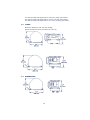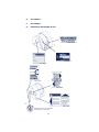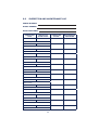
1
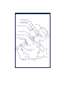
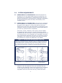
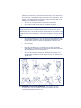
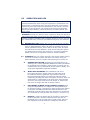
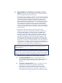
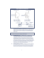
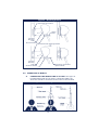
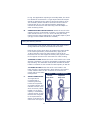
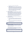
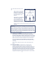
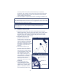
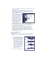
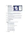
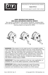
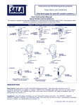
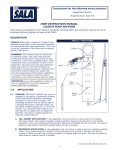
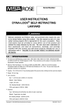
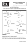
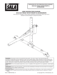
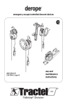
Instructions for the following series products: DIGITAL WINCH See the last pages for specic model numbers USER INSTRUCTION MANUAL ADVANCED DIGITAL WINCH This manual is intended to meet industry standards, including OSHA 1910.146 and ANSI Z117.1, and should be used as part of an employee training program as required by OSHA. WARNING: This product is to be used as part of a complete system. The user must follow the manufacturer’s instructions for each component of the complete system. These instructions must be provided to the user of this equipment. Manufacturer’s instructions must be followed for proper use and maintenance of this product. Alterations or misuse of this product, or failure to follow instructions may result in serious injury or death. IMPORTANT: If you have questions on the use, care, application, or suitability for use of this safety equipment, contact Capital Safety. IMPORTANT: Before using this equipment record the product identication information from the ID label on the winch in the inspection and maintenance log in section 9.0 of this manual. © Copyright 2006 Ad- Figure 1 - Parts Identication Secondary Drive Hub 9:1 retrieval ratio Primary Drive Hub 4:1 retrieval ratio Winch Cable Retainer Spring Carrying Handle Permanent Crank Arm Manual Drive Hubs (Optional) Power Drive Hub (Optional) Universal Mounting Plate Power Drive Clutch (Optional) Removable Crank Arm (Optional) DESCRIPTIONS Digital Winches: 100 Series Winch: 100 feet of 3/16 inch wire rope. 200 Series Winch: 200 feet of 3/16 inch wire rope. 300 Series Winch: 300 feet of 3/16 inch wire rope. 1.0 APPLICATIONS 1.1 PURPOSE: Advanced Digital Series Winches are to be used for work positioning, personnel riding, material handling, climbing protection, or rescue and evacuation. These winch models are to be used with an Advanced tripod, davit arm, or other support structure, and may be used in situations where personnel or materials need to be raised or lowered up to 300 feet. 1.2 WINCH APPLICATION TYPES: A. WORK POSITIONING: The Digital Winch is used to suspend the worker in a work position, acting as the primary means of support. Applications include suspending a worker in a work seat or harness. A back-up personal fall arrest system (PFAS) must be attached to the suspended employee. NOTE: OSHA requires that manual or powered winches be independently evaluated and classied for use as a single point suspension system. See OSHA regulation 29 CFR 1926.451, and 29 CFR 1910.28. B. PERSONNEL RIDING: The Digital Winch is used to raise or lower a worker to a work level. At the work level the worker is no longer supported by the winch. A back-up PFAS must be attached to the employee while riding the winch. C. RESCUE AND EVACUATION: The Digital Winch is used to raise or lower an endangered or injured worker, or rescue personnel. Applications include permit and non-permit confined space entry work. When possible, in emergency rescue or evacuation situations, use a back-up PFAS. D. CLIMBING PROTECTION: The Digital Winch is used to protect a worker ascending or descending a fixed ladder or similar structure. It is recommended that this use of the winch be restricted to structures where other means of climbing protection; such as permanently installed ladder safety systems or personal fall arrest systems are infeasible. For this application, the following conditions must be met: • Ladder or steps are in good condition and allows for a straight, continuous climb. 3 • The worker climbing the ladder is wearing a full body harness and the winch line is connected to the dorsal (back) D-ring of the harness. • The winch operator is trained and competent in the operation of the winch. • No slack line is allowed to develop when the worker moves up or down the ladder. • Capital Safety recommends, for the Advanced series winches only, that an energy absorbing lanyard be connected between the harness dorsal D-ring and the winch line. 1.3 1.4 LIMITATIONS: The following application limitations must be considered before using this product. Failure to observe product limitations could result in serious injury or death. A. INSTALLATION: The winch must be installed in accordance with the requirements stated in section 3.0 of this manual. B. CAPACITY: The maximum working load for this product is one person with a combined maximum weight (including tools, clothes, and equipment) of 450 lbs. (204 kg). C. PERSONAL FALL ARREST SYSTEMS: Personal fall arrest systems used with the Digital Winch must meet applicable state and federal regulations and the requirements stated in section 3.3. D. PHYSICAL AND ENVIRONMENTAL HAZARDS: Use of this equipment in areas with physical or environmental hazards may require that additional precautions be taken to reduce the possibility of damage to this equipment or injury to the user. Hazards may include, but are not limited to; high heat (welding or metal cutting), acid or caustic chemicals, corrosive environments such as exposure to seawater, high voltage power lines, explosive or toxic gases, moving machinery or sharp edges. Contact Capital Safety if you have questions about the application of this equipment in areas where physical or environmental hazards are present. E. TRAINING: This equipment is to be installed and used by persons who have been trained in its correct application and use. Refer to national standards, including; ANSI Z117.1, local, state, and OSHA requirements (26 CFR 1910.146), for more information on the application of this and associated equipment. 4 2.0 SYSTEM REQUIREMENTS 2.1 COMPATIBILITY OF COMPONENTS: Advanced equipment is designed for use with Capital Safety approved components and subsystems only. Substitutions or replacements made with nonapproved components or subsystems may jeopardize compatibility of equipment and may effect the safety and reliability of the complete system. 2.2 COMPATIBILITY OF CONNECTORS: Connectors are considered to be compatible with connecting elements when they have been designed to work together in such a way that their sizes and shapes do not cause their gate mechanisms to inadvertently open regardless of how they become oriented. Contact Capital Safety if you have any questions about compatibility. Connectors ( hooks, carabiners, and D-rings) must be capable of supporting at least 5,000 lbs. (22.2kN). Connectors must be compatible with the anchorage or other system components. Do not use equipment that is not compatible. Non-compatible connectors may unintentionally disengage. See Figure 2. Connectors must be compatible in size, shape, and strength. Self locking snap hooks and carabiners are required by ANSI Z359.1 and OSHA. Figure 2 - Unintentional Disengagement (Roll-out) If the connecting element that a snap hook (shown) or carabiner attaches to is undersized or irregular in shape, a situation could occur where the connecting element applies a force to the gate of the snap hook or carabiner. This force may cause the gate (of either a self-locking or a non-locking snap hook) to open, allowing the snap hook or carabiner to disengage from the connecting point. Small ring or other non-compatibly shaped element 1. Force is applied to the snap hook. 2.3 2. The gate presses against the connecting 3. The gate opens allowing the snap hook to slip off. MAKING CONNECTIONS: Only use self-locking snap hooks and carabiners with this equipment. Only use connectors that are suitable to each application. Ensure all connections are compatible in size, shape and strength. Do not use equipment that is not compatible. Ensure all connectors are fully closed and locked. 5 Advanced connectors (snap hooks and carabiners) are designed to be used only as specied in each product’s user’s instructions. See Figure 3 for inappropriate connections. Advanced snap hooks and carabiners should not be connected: A. To a D-ring to which another connector is attached. B. In a manner that would result in a load on the gate. NOTE: Large throat opening snap hooks should not be connected to standard size D-rings or similar objects which will result in a load on the gate if the hook or D-ring twists or rotates. Large throat snap hooks are designed for use on xed structural elements such as rebar or cross members that are not shaped in a way that can capture the gate of the hook. C. In a false engagement, where features that protrude from the snap hook or carabiner catch on the anchor and without visual confirmation seems to be fully engaged to the anchor point. D. To each other. E. Directly to webbing or rope lanyard or tie-back (unless the manufacturer’s instructions for both the lanyard and connector specifically allows such a connection). F. To any object which is shaped or dimensioned such that the snap hook or carabiner will not close and lock, or that roll-out could occur. Figure 3 - Inappropriate Connections 2.4 SUPPORT STRUCTURE STRENGTH: The support structure to which the winch is installed must meet minimum strength requirements stated in section 3.4 6 3.0 OPERATION AND USE WARNING: Do not alter or intentionally misuse this equipment. Consult Capital Safety when using this equipment in combination with components or subsystems other than those described in this manual. Some subsystem and component combinations may interfere with the operation of this equipment. Use caution when using this equipment around moving machinery, electrical hazards, chemical hazards, and sharp edges. WARNING: Consult your doctor if there is reason to doubt your tness to safely absorb the shock from a fall arrest. Age and tness seriously affect a worker’s ability to withstand falls. Pregnant women or minors must not use a Advanced winch, unless for unavoidable emergency use situations. 3.1 BEFORE EACH USE: Before each use of this equipment carefully inspect it to ensure it is in good working condition. Check for worn or damaged parts. Ensure all parts are present and secure. Check operation of winch; ensure that it will lift, lower, and hold the load under normal operation. Check winch and entire system for damage and corrosion. See section 5.0 for further inspection details. Do not use if inspection reveals an unsafe condition. 3.2 PLANNING: Plan your system and how it will function before starting your work. Consider all factors that affect your safety during use. Some important points to consider when planning your system are: A. HAZARD EVALUATION: Evaluate job site hazards prior to starting work. Consult applicable OSHA and industry standards for guidelines and regulatory requirements on issues such as confined space entry, personal fall arrest systems (PFAS), and single point adjustable suspended scaffolds. B. WORK SITE GEOMETRY: The installation and use of the support structure (tripod, davit arm and base) must be consistent with the geometric requirements stated in the associated manufacturer’s instruction manuals. When suspending working lines from the support structure, check for obstructions or sharp edges in the work path. Avoid working where the user may swing and hit an object, or where lines may cross or tangle with that of another worker. C. SECONDARY OR BACK-UP FALL ARREST SYSTEM: When using the Digital Winch as a support for work positioning or for personnel riding, a secondary or back-up fall arrest system is required. See OSHA 29 CFR 1910.28 and 1926.451. The Advanced tripod and davit arm have provisions for connection of a secondary or back-up PFAS. See sections 3.3 and 3.5 (A). D. RESCUE: A means of dealing with an accident or emergency must be planned in advance. Response time can play an important role in the survival of an injured worker. Users of this equipment must be trained in emergency procedures. 7 3.3 REQUIREMENTS FOR PERSONAL FALL ARREST SYSTEMS (PFAS): PFAS used with the Digital Winch and support structure must meet applicable OSHA requirements. • The PFAS should be rigged to minimize any potential free fall and never allow a free fall greater than 6 ft. (1.8m). It is required that the PFAS used with this equipment include a full body harness as the body support component. PFAS’s that incorporate full body harnesses must maintain fall arrest forces below 1,800 lbs. (8kN) and arrest the fall within 42 in. (1.1m). Body belts, unless incorporated into a full body harness, are not recommended for use with this equipment. A typical PFAS includes a full body harness, connecting subsystem or component (self retracting lifeline or lifeline and rope grab), and the necessary connectors to couple the system together. • Anchorages selected for PFAS must sustain static loads, applied in the directions permitted by the PFAS, of at least; (A) 3,600 lbs. (16kN) when certication exists (see ANSI Z359.1 for certication denition), or (B) 5,000 lbs. (22.2kN) in the absence of certication. When more than one PFAS is attached to an anchorage, the anchorage strengths set forth in (A) and (B) must be multiplied by the number of PFAS attached to the anchorage. Per OSHA 1926.500 and 1910.66: Anchorages used for attachment of a PFAS shall be independent of any anchorage being used to support or suspend platforms, and must support at least 5,000 lbs. (22.2kN) per user attached, or be designed, and used as part of a complete PFAS which maintains a safety factor of at least two, and is supervised by a qualied person. WARNING: Read and follow manufacturer’s instructions for the personal fall arrest equipment selected for use with the winch and support structure. IMPORTANT: Body belts are not allowed for free fall situations. Body belts increase the risk of injury during fall arrest in comparison to a full body harness. Limited suspension time and the potential for improperly wearing a body belt may result in added danger to the user’s health. 3.4 INSTALLATION OF WINCH TO DAVIT ARM OR TRIPOD: A. LOAD REQUIREMENTS: Figure 4 illustrates the winch mounted to the support structure and the load requirements. The mounting bracket must support the loads shown in Figure 4. B. GEOMETRIC REQUIREMENTS: Refer to the support structure manufacturer’s instructions for geometric requirements. Installations of the winch to support structures other than those provided by Capital Safety must meet the geometric requirements shown in Figure 4. Position the support structure so the load and the lifeline of the winch can be directed over the 8 Figure 4 Required Load Strength 2,500 lbs. in direction of pull 625 ft-lbs moment load 2,500 lbs. in direction of pull 1,900 ft-lbs moment load Left Hand Retrieve (cable feeds off top) Right Hand Retrieve (cable feeds off bottom) 36 In. Min Recommended Directional Sheave Wire rope directional sheaves must have a minimum tread diameter of 2.5 in. work area when installed. For personnel use, do not position the support structure where the worker will have to swing under the support structure to reach the work area. Avoid positioning the support structure where the working line may abrade against sharp edges. IMPORTANT: Position the winch and support structure in a location which allows the operator to safely use the winch. C. MOUNTING PLATE: The Digital Winch is equipped with a universal mounting plate. The universal mounting plate is designed to attach to the quick mount bracket and the Advanced series winch mount bracket (see Figure 5) and will accommodate most other support structures which meet the requirements specified in section 3.3. See the support system user manual for mounting information or contact Capital Safety for optional mounting kits. When attaching the winch to the support, one of the attachment features (i.e., bolt or stud) must capture the structural carrying handle. D. WELDED INSTALLATIONS: If welding the mounting bracket to a support structure it is recommended that the welding be done by a certified welder. Portions of the mounting bracket that have been exposed due to welding should be painted or 9 Figure 5 - Mounting Bracket Advanced Quick Mount Clamp Knob Universal Mounting Plate Structural Handle Advanced Series Mounting Bracket Universal Mounting Plate Structural Handle Connecting device must capture handle otherwise protected from corrosion. 3.5 OPERATION OF WINCH: A. CONNECTING THE WINCH LINE TO A LOAD: See Figure 6. For applications that do not require a secondary PFAS, the winch line should be connected to the worker’s harness back Figure 6 - Connecting to Winch Line 10 D-ring. For applications requiring a secondary PFAS, the winch line should be connected to a Y-type lanyard and this lanyard should be attached to the worker’s harness shoulder D-rings. The secondary lifeline should be connected to the worker’s harness back D-ring. For material handling applications, connect the winch line to the load using a tie-off adapter or other anchoring device. B. OPERATING THE DIGITAL WINCH: Attach the winch to the support structure as described in section 3.4. Install the winch crank handle into the 9:1 or 4:1 drive hub and push firmly inward until the spring loaded tab on the handle snaps in place (the grip on the handle should face outward). NOTE: The 4:1 drive is used under normal working conditions for raising and lowering workers To remove the crank handle from the hub, push down on the spring loaded tab and pull the handle out of the hub. Feed the line off the winch drum by rotating the crank handle in the lowering direction (counterclockwise). Apply about 10 lbs of tension to the line while feeding it off the drum. Route the line over the support structure pulley system. Refer to the support structure user instructions for cable routing. TO RAISE A LOAD: Rotate the winch crank handle in the raise direction (clockwise). To hold or momentarily suspend the load, stop cranking. The automatic clutch/brake will hold the load if handle is released. Do not exceed the rated capacity of 450 lbs. TO LOWER A LOAD: Rotate the winch crank handle in the lower direction (counterclockwise). When lowering line without a load, maintain about 10 lbs. of tension on the line to aid payout and prevent cable Figure 7 - Impact Indicator entanglement. C. IMPACT INDICATOR: The Digital Winch is supplied with a connecting swiveling hook that incorporates an impact indicator. This indicator functions if the winch is severely impact loaded or if the lifting capacity is exceeded by a preset amount. A hook that has been subjected to an impact load will display a red band in the swivel area. See Figure 7. 11 Normal Snap Hook Impacted Snap Hook Red band indicates impact load. See section 5.0 for inspection of impact indicator. D. WINCH REMOVAL: Disconnect the lifeline from the worker’s harness or from the material load. Maintain at least a 10 lb. load on the lifeline while turning the crank handle clockwise to wind the lifeline onto the spool. Retract the lifeline through the support structure. See the support structure user instructions. Continue to wind the lifeline onto the winch drum until the copper ferrules and thimble contact the drum. Disconnect the winch from the support structure. Refer to the support structure user instructions for details. 3.6 LOAD ATTACHMENT: Pull on the snap hook while cranking the handle counterclockwise to extend lifeline until there is sufcient line to comfortably attach to the worker or load. Perform the attachment away from the entrance so there is no danger that the worker or load will fall. Use two hands when attaching the lifeline: one hand maintaining tension on the lifeline, the other hand to depress the lock and open the gate on the snap hook. Insert the hook into the harness D-ring. Release the gate and lock and ensure the snap hook is securely locked onto the D-ring. 3.7 SYSTEM INTEGRITY: Verify the integrity of the attachment and support system as follows: A. Crank the winch handle in the raise direction until the line is snug. The worker should slowly transfer their weight to the harness and lifeline until they are able to lift both feet off the ground. B. Make sure the winch holds the worker in a stationary position. Also adjust the fit of the harness at this time so that it does not pinch, chafe or bind. IMPORTANT: Do not use winch for lifting or lowering of more than one person, except for emergency situations. The maximum lifting force is 450 lbs. 3.8 LOWERING A WORKER: The attendant should turn the winch handle counterclockwise to pay out the lifeline. The attendant should keep a gloved hand on the lifeline as it extends to keep a slight tension on the lifeline. If the line becomes tight or slack during use, communicate with the suspended worker to determine whether there is a problem. Correct any problems before proceeding. WARNING: If the cranking tension eases during lowering, the person or material being lowered has reached a work level or obstruction. Do not continue cranking without communicating with the person or checking the material being lowered. Always keep the cable tension 12 rm. Slack cable could cause a free fall. While a worker is suspended maintain the swing angle at less than 5°. The worker can be seriously injured in a swing fall at more than 5°. See Figure 8. Figure 8 - Swing Angle Anchor 5° Max. 5° Max. Lifeline If the worker is not suspended and there is no chance of a fall. The attendant may pay out sufficient line (2 ft. max) so the worker can work comfortably. The attendant should hold the line so there is always a slight tension on it. Maintain constant communication between the worker and the attendant. WARNING: The last 10 feet of the lifeline has a red marker and should not be unwound from the drum. This length provides the required wrap on the drum to properly anchor the lifeline and insures that the lifeline wrap direction is correct. Stop extending the lifeline when you see the red marker. The lifeline must wind onto the drum by turning the crank handle in the “raise” (counterclockwise) direction only. Check periodically to see that the lifeline is winding evenly on the drum. Use gloves when handling the lifeline. 3.9 RETRIEVING A WORKER: Communicate with the worker when preparing to retrieve them and maintain communication throughout the procedure. Place the crank handle in the 4:1 or 9:1 drive hub as appropriate to keep the turning force in a comfortable range. Turn the crank arm in the clockwise direction to retract the lifeline and retrieve the worker. Maintain an even retrieval rate. If the winch handle turning load suddenly increases, stop and investigate. Determine the cause and correct the problem before continuing. Upon retrieval, support the load or worker and disconnect the lifeline. 3.10 INERTIAL BRAKE: The Digital Winch is designed with a constantly engaged brake that will hold a suspended load whenever the crank handle is released. This brake is composed of three independent pawls. All three pawls would have to become inoperable for the primary brake to fail. The winch has a secondary inertia brake in case the primary brake should fail. If the primary brake failed, the winch would free-wheel until the inertia brake engaged and stopped the cable. No more than 3 ft. (1m) of cable 13 deploys before the inertia brake engages. If the inertia brake engages, the operator can still extend or retract the lifeline from its stopped position by turning the crank arm. However, if the crank arm is released, the winch would free-wheel again until the inertial brake engages again. Use the crank arm to retrieve the entrant or load from the conned space without releasing the handle. After the entrant is removed from the conned space, release the lifeline and promptly remove the winch from service and return it to Capital Safety or an approved repair facility for repair. 3.11 LEFT HAND RETRIEVE: The Digital Winch can be adjusted to work as a left hand retrieve. To make this adjustment, remove the cable retention spring and attach it to the hole on the other end of the mounting plate using the same hardware. Remove the carrying handle by removing the two screws attaching it to the winch and replace it on the other end of the winch. Use a removable thread lock such as Loctite 242 to secure all fasteners. The winch will now mount on mounting brackets with the handle on the left side of the winch. IMPORTANT: The cable will feed off the top of the drum in this conguration, changing the moment load requirements as specied in Figure 4. 4.0 4.1 TRAINING It is the responsibility of the user to assure they are familiar with these instructions, and are trained in the correct care and use of this equipment. User must also be aware of the operating characteristics, application limits, and the consequences of improper use of this equipment. IMPORTANT: Training must be conducted without exposing the trainee to a fall hazard. Training should be repeated on a periodic basis. 5.0 5.1 INSPECTION FREQUENCY: • Before Each Use: Visually inspect per steps listed in sections 5.2 and 5.3. • Annually: A formal inspection of the winch should be done by a competent person other than the user. See sections 5.2 and 5.3 for guidelines. Record results in the inspection and maintenance log in section 9.0. • Every 30,000 cycles or 5 years (whichever comes rst): It is recommended that the winch be serviced by a factory authorized service center or the manufacturer. Extreme working conditions may require increasing the frequency of inspections. Annual 14 servicing shall include, but not be limited to, an intensive inspection and cleaning of all internal and external components. Failure to provide proper service may shorten product life and could endanger performance. • After An Impact: Inspect entire winch according to section 5.2. WARNING: If the winch has been subjected to impact forces, it must be immediately removed from service and inspected. If the winch fails to pass the inspection, do not use. The equipment must be sent to an authorized service center for repair. IMPORTANT: Extreme working conditions (harsh environment, prolonged use, etc.) may require increasing the frequency of inspections. 5.2 GENERAL INSPECTION: • Inspect all screws, bolts and nuts. Ensure they are securely attached and tight. Check to see if any bolts, nuts or other parts are missing, or have been substituted or altered in any way. Inspect covers and housings. Ensure they are free of cracks, dents, corrosion or other damage. • Permanent crank arm (if present) must be free of Figure 9 - Crank Handle Screws cracks, dents, corrosion and excessive wear. The handle must not be bent or distorted and must rotate freely. The locking pin must lock and hold the handle perpendicular to the arm • Removable crank arm (if present) must lock positively into each of the drive hubs and be free of cracks, bends, or other damage. Check that Handle Anchor Screws each handle on the crank arm is tight. See Figure 9. Use Loctite262 or equivalent Figure 10 - Brake Wear Indicator thread lock on the anchor screws if required to keep Green Section them tight. Do not use unless the crank arm is fully functional. Indicator Pin • Connecting hook must not be damaged, broken, distorted, or have any sharp Red Section edges, burrs, cracks, worn parts, or corrosion. Ensure the connecting hook works 15 properly. Hook gate must move freely and lock upon closing. Hook must swivel freely. • Inspect the brake wear indicator. See Figure 10. This is located in the center of the 4:1 drive hub. If the indicator is in the red section, remove the winch from service and return to Capital Safety or an approved repair Figure 11 - Digital Cycle Counter center for repair. • Inspect all identication and Digital warning labels, ensuring that Cycle they are legible and securely Counter attached. See section 8.0. • Check the digital counter, (see Figure 11) if it exceeds 30,000 cycles from the last factory service recorded in the inspection log in Section 9, return the winch to Capital Safety or an authorized repair center for service. • Check operation of the winch in high and low speed positions; it must crank up and down freely. Stiff or rough operation may indicate a worn gear or bearing. • Inspect the Cable Retaining Spring assuring that it applies pressure against the line. If the plastic wear pad needs to be replaced, return the winch to an authorized service center. • Inspect each system component (support structure, back-up fall arrest system, body support, connectors, etc.) according to manufacturer’s instructions. 5.3 LIFELINE INSPECTION WIRE ROPE: Inspect entire length of wire rope assembly starting at the hook. Always wear protective gloves when inspecting wire rope. A. B. Inspect for broken wires by passing the wire rope through gloved hands, flexing it every few inches to expose breaks. Broken wires can be removed by bending the wire back and forth parallel to the rope length. Do not attempt to pull wires out of rope. Inspect for kinks, cuts, crushed burned areas, or other damage. See Figure 12. Wire rope with serious damage must be removed from service. The wire rope assembly must 16 Figure 12 - Wire Rope Flaws Kinked wire rope Broken wires Bird-caging Welding splatter be replaced by an authorized service center if there are six or more randomly distributed broken wires in one lay, or three or more broken wires in one strand in one lay. Note: A “lay” of wire rope is the length of wire rope that it takes for a strand (the larger groups of wires) to complete one revolution or twist along the rope. C. The wire rope assembly must be replaced by an authorized service center if there are any broken wires within one inch of the metal compression sleeves at either end of the assembly. D. Inspect entire length of wire rope for signs of corrosion. Severely corroded wire rope must be replaced. SYNTHETIC ROPE: Inspect for the following if the winch uses synthetic rope: A. Inspect for concentrated wear, frayed strands, broken yarns, cuts, and abrasions. The line must be free of knots, excessive soiling, heavy paint buildup, and rust staining throughout its length. B. The line must be free of chemical or heat damage, indicated by brown, discolored, or brittle areas. C. The line must be free of ultraviolet damage, indicated by discoloration and the presence of splinters and slivers on the rope surface. D. All of the above factors are known to reduce rope strength. As a rule of thumb, rope strength is reduced proportional to the cross sectional area of the rope damaged. Damaged or questionable rope must be replaced by an authorized service center. 5.4 If inspection or operation reveals a defective condition, remove the winch from service immediately and contact an authorized service center for repair. NOTE: Only Capital Safety or parties authorized in writing may make repairs to this equipment. 6.0 6.1 MAINTENANCE, SERVICING, STORAGE Periodically clean the exterior of the winch using water and a mild detergent solution. Clean labels as required. At least twice a year, clean and lubricate the wire rope. Do not use solvents to clean the wire rope as they will remove internal lubrication. Lubricate wire rope using a cloth (wearing gloves) and a light machine oil. 17 6.2 LUBRICATION OF Figure 13 - Brake Pad Lube Hole DIGITAL WINCH BRAKE PADS: A light lubricant such as WD-40 Lube hole in center should be sprayed into of primary the brake pad lubrication drive hub holes every ve to eight uses of the winch. Two lube holes are located along the back of the housing. A label marks their location. A third lube hole can be found at the center of the primary drive hub, in the middle of the brake pad wear indicator. See Figure 13. 6.3 Replacement parts, as well as additional maintenance and servicing procedures, must be completed by a factory authorized service center. An authorization and a return number must be issued by Capital Safety. 6.4 Store this equipment in a cool, dry, clean environment out of direct sunlight. Avoid areas where chemical vapors exist. Inspect after any period of extended storage. 6.5 Clean and store body support, support structure, and associated system components according to separate instructions provided with that equipment. 7.0 7.1 SPECIFICATIONS MATERIALS: Housing: Cast Aluminum with powder coat paint nish. Lifeline: •3/16 in. (5mm) Stainless Steel •1/4 in. (6mm) Stainless Steel •3/8 in. (10mm) Stainless Steel •5/8 in. (16mm) Stainless Steel •3/16 in. (5mm) Non-rotating Stainless Steel •3/16 in. (5mm) Galvanized Steel •3/16 in. (5mm) Technora Cord •1/4 in. (6mm) Technora Rope •5/16 in. (8mm) •3/8 in. (10mm) •1/2 in. (12mm) •5/8 in. (16mm) 7.2 Kernmantle Kernmantle Kernmantle Kernmantle Rope Rope Rope Rope WEIGHT 18 100 Series Advanced Digital Winch: 26.5 lbs (12kg) plus lifeline. 200 Series Advanced Digital Winch: 27 lbs (12.2kg) plus lifeline. 300 Series Advanced Digital Winch: 27.5 lbs (12.4kg) plus lifeline. 7.3 LOADS: Maximum Working Load: 450 lbs (204kg) Winch Mechanism Proof Load 5000 lbs (22.2 d) 7.4 DIMENSIONS: 19 A. 100 SERIES: .75 (19mm) 2.06 (52.3mm) .406 (10.3mm) 20 2.06 (52.3mm) B. 200 SERIES: C. 300 SERIES: D. UNIVERSAL MOUNTING PLATE: PN 11622 PN 12817 PN 11623 PN 11624 PN 17206 PN 11621 Warranty is void if this label and putty are removed. 21 9.0 INSPECTION AND MAINTENANCE LOG SERIAL NUMBER: MODEL NUMBER: DATE PURCHASED: INSPECTION DATE INSPECTION ITEMS NOTED Approved By: Approved By: Approved By: Approved By: Approved By: Approved By: Approved By: Approved By: Approved By: Approved By: Approved By: Approved By: Approved By: Approved By: 22 CORRECTIVE ACTION MAINTENANCE PERFORMED This instruction applies to the following models: 13448 14602 18013 18014 18015 18016 18017 18018 18019 18020 18021 18483 18484 18485 18486 18487 18488 18489 18490 18491 18497 18498 18499 18551 18552 18553 18554 18555 18556 18557 18558 18559 18560 18561 18562 18563 18564 18565 18566 18567 18568 18569 18570 18571 18572 18573 18574 18575 18576 18577 18578 18579 18580 18581 18582 18583 18584 18585 18586 18587 18588 18589 18590 18591 18592 18593 18594 18595 18596 18597 18598 18599 18601 18602 18603 18604 18605 18606 18607 18608 18609 18610 18611 18612 18613 18614 18615 18616 18617 18618 18619 18620 18621 18622 18623 18624 18625 18626 18627 18628 18629 18630 18631 18632 18633 18634 18635 18636 18637 18638 18639 18640 18641 18642 18643 18644 18645 18646 18647 18648 18649 18650 18651 18652 18653 18654 18655 18656 18657 18658 18659 18660 18661 18662 18663 18664 18665 18705 18706 18707 Additional model numbers may appear on the next printing of these instructions 23 WARRANTY Equipment offered by Capital Safety is warranted against factory defects in workmanship and materials for a period of two years from date of installation or use by the owner, provided that this period shall not exceed two years from date of shipment. Upon notice in writing, Capital Safety will promptly repair or replace all defective items. Capital Safety reserves the right to elect to have any defective item returned to its plant for inspection before making a repair or replacement. This warranty does not cover equipment damages resulting from abuse, damage in transit, or other damage beyond the control of Capital Safety. This warranty applies only to the original purchaser and is the only one applicable to our products, and is in lieu of all other warranties, expressed or implied. A Capital Safety Company USA Canada 3833 SALA Way Red Wing, MN 55066-5005 Toll Free: 800-328-6146 Phone: (651) 388-8282 Fax: (651) 388-5065 www.capitalsafety.com 260 Export Boulevard Mississauga, Ontario L5S 1Y9 Toll Free: 800-387-7484 Phone: (905) 795-9333 Fax: (905) 795-8777 www.capitalsafety.com This instruction manual is available for download at www.capitalsafety.com. I S O 9001 Certicate No. FM 39709 Form: 8511324 Rev: B