1
Marathon
with Windows® Embedded Standard
with Windows® 7 Professional
with Windows XP® Professional
User’s Guide
Disclaimer
Honeywell International Inc. (“HII”) reserves the right to make changes in specifications and other information contained in this
document without prior notice, and the reader should in all cases consult HII to determine whether any such changes have been
made. The information in this publication does not represent a commitment on the part of HII.
HII shall not be liable for technical or editorial errors or omissions contained herein; nor for incidental or consequential damages
resulting from the furnishing, performance, or use of this material.
HII disclaims all responsibility for the selection and use of software and/or hardware to achieve intended results.
This document contains proprietary information that is protected by copyright. All rights are reserved. No part of this document
may be photocopied, reproduced, or translated into another language without the prior written consent of HII.
© 2011-2015 Honeywell International Inc. All rights reserved.
Web Address: www.honeywellaidc.com
Trademarks
RFTerm is a trademark or registered trademark of EMS Technologies, Inc. in the United States and/or other countries.
Microsoft®, Windows®, Windows XP®, ActiveSync®, MSN, Outlook®, Windows Mobile®, the Windows logo, and Windows Media
are registered trademarks or trademarks of Microsoft Corporation in the United States and/or other countries.
Intel® and Atom™ are trademarks or registered trademarks of Intel Corporation or its subsidiaries in the United States and other
countries.
Laird Technologies, the Laird logo, Summit Data Communications, the Summit logo, and “Connected. No Matter What” are
trademarks of Laird Technologies, Inc.
microSD and microSDHC are trademarks or registered trademarks of SD-3C, LLC in the United States and/or other countries.
The Bluetooth® word mark and logos are owned by the Bluetooth SIG, Inc.
Symbol® is a registered trademark of Symbol Technologies. MOTOROLA, MOTO, MOTOROLA SOLUTIONS and the Stylized M
Logo are trademarks or registered trademarks of Motorola Trademark Holdings, LLC and are used under license.
RAM® and RAM Mount™ are both trademarks of National Products Inc., 1205 S. Orr Street, Seattle, WA 98108.
Freefloat, Freefloat Link*One and Freefloat Access*One are trademarks of Freefloat, Mölndalsvägen 30B, SE-412 63Gothenburg, Sweden.
Qualcomm® is a registered trademark of Qualcomm Incorporated. Gobi is a trademark of Qualcomm Incorporated.
OneClick Internet is WebToGo’s patented connection manager customized for Honeywell mobile devices. OneClick Internet
documentation is copyright 2010 by WebToGo and modified by Honeywell with WebToGo’s express permission.
Verizon® is a registered trademark of Verizon Trademark Services LLC.
T-MOBILE® is a registered trademark of Deutsche Telekom AG.
AT&T® is a registered trademark of AT&T Intellectual Property.
AuthenTec, TouchChip, Eikon and TrueSuite are registered trademarks and QuickSec, SafeXcel, DRM Fusion, SafeZone, Eikon,
TrueNav, SteelCoat, TouchStone, DataDefender, MatrixSSL, MatrixDLS, TouchStone, SteelCoat, KeepVault, KeepSync and
KeepSafe are trademarks of AuthenTec, Inc.
PenMount, and the Pen Mount logo are registered trademarks of Salt International Corporation, Taipei, Taiwan, R.O.C.
Wi-Fi®, WMM®, Wi-Fi Mutlimedia™, Wi-Fi Protected Access®, WPA™, WPA2™ and the Wi-Fi CERTIFIED™ logo are trademarks or registered trademarks of Wi-Fi Alliance.
Other product names or marks mentioned in this document may be trademarks or registered trademarks of other companies
and are the property of their respective owners.
Patents
For patent information, please refer to www.hsmpats.com.
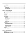
Table of Contents
Chapter 1 - Marathon Agency Compliance
Laser Warnings .................................................................................................................................. 1-1
Laser Label Location.......................................................................................................................... 1-1
Laser Safety Statement...................................................................................................................... 1-1
FCC Part 15 Statement...................................................................................................................... 1-2
FCC 5GHz Statement ........................................................................................................................ 1-2
Canadian Compliance........................................................................................................................ 1-2
CE Mark ............................................................................................................................................. 1-3
RF Notices ......................................................................................................................................... 1-3
Bluetooth ............................................................................................................................................ 1-3
Honeywell Scanning & Mobility Product Environmental Information.................................................. 1-3
Dealer License - Republic of Singapore............................................................................................. 1-3
Vehicle Power Supply Connection Safety Statement ........................................................................ 1-3
Chapter 2 - Getting Started
Overview ............................................................................................................................................ 2-1
About this Guide................................................................................................................................. 2-1
Microsoft Windows License Agreement (First Boot) .......................................................................... 2-2
WWAN and the US and Canada........................................................................................................ 2-2
Out of the Box .................................................................................................................................... 2-2
Initial Setup for Marathon ................................................................................................................... 2-2
Hardware Setup........................................................................................................................... 2-2
Software Setup ............................................................................................................................ 2-3
Front View .......................................................................................................................................... 2-4
Rear View........................................................................................................................................... 2-4
Bottom View ....................................................................................................................................... 2-5
Right Side View.................................................................................................................................. 2-5
Left Side View .................................................................................................................................... 2-5
LEDs and Indicators........................................................................................................................... 2-6
Power Button ............................................................................................................................... 2-6
Status LEDs................................................................................................................................. 2-6
Keyboard Indicators..................................................................................................................... 2-6
About the Battery ............................................................................................................................... 2-7
Charge or Recharge the Main Battery ......................................................................................... 2-7
Charge or Recharge the Extended Battery ................................................................................. 2-7
Tapping the Touch Screen with a Stylus............................................................................................ 2-8
Using the Biometric Mouse ................................................................................................................ 2-8
Adjusting Display Brightness.............................................................................................................. 2-8
Attaching the Hand Strap ................................................................................................................... 2-9
Attaching the Shoulder Strap ........................................................................................................... 2-10
Connecting USB Devices................................................................................................................. 2-11
Connecting an AC/DC Power Supply............................................................................................... 2-11
Connecting an Audio Device............................................................................................................ 2-12
Software Configuration Options ....................................................................................................... 2-12
Setting Date and Time ............................................................................................................... 2-12
Setting Power Management ...................................................................................................... 2-12
Setting Speaker Volume ............................................................................................................ 2-12
Connecting Bluetooth Devices .................................................................................................. 2-13
i
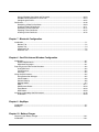
Restart/Shutdown.......................................................................................................................2-13
Calibrating the Touch Screen ...........................................................................................................2-13
On-Screen Keyboard ........................................................................................................................2-13
Data Entry.........................................................................................................................................2-13
Keyboard Data Entry..................................................................................................................2-13
Bar Code Data Entry ..................................................................................................................2-13
Magnetic Card Data Entry..........................................................................................................2-14
Touch Screen Data Entry...........................................................................................................2-14
Chapter 3 - Hardware Configuration
Processor, Memory and Storage ........................................................................................................3-1
Display ................................................................................................................................................3-1
Audio ..................................................................................................................................................3-1
Wireless Communication ....................................................................................................................3-1
Power Management ...........................................................................................................................3-1
Power Input / Main Battery .................................................................................................................3-1
Backup Battery ...................................................................................................................................3-2
Power Button ......................................................................................................................................3-2
Reset Button .......................................................................................................................................3-2
External Connectors ...........................................................................................................................3-3
USB Connectors ..........................................................................................................................3-3
Audio Connector ..........................................................................................................................3-3
Power Supply Connector .............................................................................................................3-3
Antenna Signal Pathway ..............................................................................................................3-3
Docking Connector.......................................................................................................................3-3
Keyboard ............................................................................................................................................3-3
Backlighting..................................................................................................................................3-3
Sticky Keys...................................................................................................................................3-3
Sticky Key Indicators....................................................................................................................3-3
Keyboard Help .............................................................................................................................3-4
Biometric Mouse .................................................................................................................................3-4
Security Features .........................................................................................................................3-4
Fingerprint Reader / Biometric Mouse .........................................................................................3-5
Navigation ....................................................................................................................................3-5
Touch Screen .....................................................................................................................................3-6
Calibrating the Touch Screen.......................................................................................................3-6
Refresh the Touch Screen Calibration Points ..............................................................................3-6
Disabling the Touch Screen .........................................................................................................3-6
Using a Dock and a Second Monitor............................................................................................3-6
The Display.........................................................................................................................................3-7
Adjust Display Brightness ............................................................................................................3-7
Cleaning the Display ....................................................................................................................3-7
Chapter 4 - Software Configuration
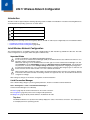
Introduction .........................................................................................................................................4-1
Operating System ...............................................................................................................................4-1
Microsoft Windows Setup and Configuration......................................................................................4-1
Microsoft Windows License Agreement (First Boot) ....................................................................4-1
ii
Drive C Folder Structure ..............................................................................................................4-1
Software Loaded on Drive C ........................................................................................................4-2
Control Panel......................................................................................................................................4-2
System Info Panel ........................................................................................................................4-2
Display Panel ...............................................................................................................................4-2
Power Options Panel ...................................................................................................................4-3
TruePrint Panel ............................................................................................................................4-3
User Accounts Panel....................................................................................................................4-3
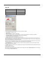
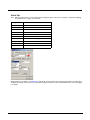
Wi-Fi Icon .....................................................................................................................................4-3
Network Configuration ........................................................................................................................4-4
802.11 Wireless Radios ...............................................................................................................4-4
Ethernet Connector ......................................................................................................................4-4
GPS (Optional).............................................................................................................................4-4
WWAN .........................................................................................................................................4-4
Bluetooth ......................................................................................................................................4-4
Chapter 5 - Using Peripherals / Accessories
Attaching an Extended Battery ...........................................................................................................5-1
Installing a SIM Card ..........................................................................................................................5-3
Replacing the Main Battery ................................................................................................................5-4
Bar Code Readers..............................................................................................................................5-6
2D Imager...........................................................................................................................................5-6
Magnetic Stripe Reader ......................................................................................................................5-6
Loading an Operating System on the Marathon .................................................................................5-7
The Marathon Drivers CD-ROM...................................................................................................5-7
Using the Recovery DVD .............................................................................................................5-7
Chapter 6 - 802.11 Wireless Network Configuration
Introduction .........................................................................................................................................6-1
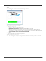
Laird Wireless Network Configuration ................................................................................................6-1
Important Notes............................................................................................................................6-1
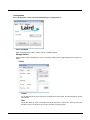
Laird Connection Manager...........................................................................................................6-1
Sign-On vs. Stored Credentials..................................................................................................6-12
Windows Certificate Store vs. Certs Path ..................................................................................6-14
Configuring the Profile................................................................................................................6-17
..........................................................................................................................................................6-36
Summit Wireless Network Configuration ..........................................................................................6-36
Important Notes..........................................................................................................................6-36
Summit Client Utility ...................................................................................................................6-37
Wireless Zero Config Utility........................................................................................................6-38
Main Tab ....................................................................................................................................6-39
Admin Login ...............................................................................................................................6-40
Profile Tab..................................................................................................................................6-41
Status Tab..................................................................................................................................6-44
Diags Tab...................................................................................................................................6-45
Global Tab..................................................................................................................................6-46
Sign-On vs. Stored Credentials..................................................................................................6-52
Using Stored Credentials ...........................................................................................................6-52
Using a Sign On Screen.............................................................................................................6-52
iii
Using a Windows User Name and Password ............................................................................6-53
Windows Certificate Store vs. Certs Path ..................................................................................6-54
Configuring the Profile................................................................................................................6-55
Certificates........................................................................................................................................6-69
Generating a Root CA Certificate...............................................................................................6-69
Installing a Root CA Certificate ..................................................................................................6-71
Generating a User Certificate.....................................................................................................6-72
Exporting a User Certificate .......................................................................................................6-75
Installing a User Certificate ........................................................................................................6-76
Chapter 7 - Bluetooth Configuration
Introduction .........................................................................................................................................7-1
Devices Tab .................................................................................................................................7-2
Options Tab..................................................................................................................................7-4
COM Ports Tab ............................................................................................................................7-5
Hardware Tab ..............................................................................................................................7-6
Chapter 8 - OneClick Internet Wireless Configuration
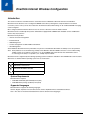
Introduction .........................................................................................................................................8-1
System Requirements..................................................................................................................8-1
Supported Languages..................................................................................................................8-1
Preparing for Initial Use on the Marathon ...........................................................................................8-2
Install SIM Card............................................................................................................................8-2
Load Firmware .............................................................................................................................8-2
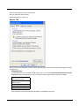
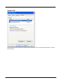
Activation......................................................................................................................................8-2
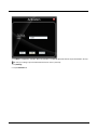
Using OneClick Internet......................................................................................................................8-5
Using Connection Manager..........................................................................................................8-5
Menu Buttons ..............................................................................................................................8-6
Statistics Display ..........................................................................................................................8-6
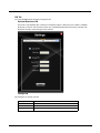
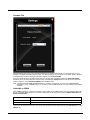
Settings Button.............................................................................................................................8-7
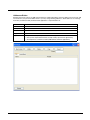
SMS ...........................................................................................................................................8-17
Web Browser Button ..................................................................................................................8-20
Email Button...............................................................................................................................8-20
GPS Button ................................................................................................................................8-20
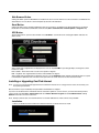
Installing or Upgrading OneClick Internet .........................................................................................8-20
Installation ..................................................................................................................................8-20
Chapter 9 - KeyMaps
Introduction .........................................................................................................................................9-1
KeyMaps.............................................................................................................................................9-1
Chapter 10 - Battery Charger
Unpacking your Battery Charger ......................................................................................................10-1
Introduction .......................................................................................................................................10-1
iv
Cautions and Warnings ....................................................................................................................10-2
Battery Charger..........................................................................................................................10-2
Lithium-Ion Battery Pack ............................................................................................................10-2
Battery Charger Top View ................................................................................................................10-3
Extended Battery Back View ............................................................................................................10-3
Installation ........................................................................................................................................10-4
Assemble the Power Supply ......................................................................................................10-4
Setup..........................................................................................................................................10-4
Charging Batteries............................................................................................................................10-4
Inserting a Battery into the Charging Pocket..............................................................................10-5
Removing the Battery from the Charging Pocket.......................................................................10-5
Interpreting the Charging Pocket LEDs ............................................................................................10-6
Charge Timer....................................................................................................................................10-6
Power LED .......................................................................................................................................10-6
Battery Charger Help ........................................................................................................................10-7
Charger Cleaning, Storage and Service ...........................................................................................10-8
Cleaning .....................................................................................................................................10-8
Storage.......................................................................................................................................10-8
Service .......................................................................................................................................10-8
Battery Cleaning, Storage and Service ............................................................................................10-8
Cleaning .....................................................................................................................................10-8
Storage.......................................................................................................................................10-8
Service .......................................................................................................................................10-8
Chapter 11 - Desktop Dock and Powered Vehicle-Mount Dock
Unpacking your Docks......................................................................................................................11-1
Overview...........................................................................................................................................11-1
Desktop Dock ...................................................................................................................................11-1
Quick Start - Desktop Dock........................................................................................................11-1
Preparing the Dock for Use........................................................................................................11-2
Table Mounting ..........................................................................................................................11-2
Desktop Dock Footprint..............................................................................................................11-2
Assemble/Attach the AC Power Adapter ...................................................................................11-3
Connect Cables..........................................................................................................................11-4
Using a Dock and a Second Monitor..........................................................................................11-4
Status LEDs ...............................................................................................................................11-5
Docking and Undocking .............................................................................................................11-6
Inserting and Removing the Extended Battery...........................................................................11-6
Desktop Dock Help ....................................................................................................................11-7
Desktop Dock Maintenance .......................................................................................................11-8
Desktop Dock Cleaning..............................................................................................................11-8
Powered Vehicle-Mounted Dock ......................................................................................................11-9
Preparing the Vehicle Mounted Dock for use.............................................................................11-9
Quick Start - Vehicle Mounted Dock ..........................................................................................11-9
Front View ................................................................................................................................11-10
Back View ................................................................................................................................11-11
Vehicle Dock LEDs ..................................................................................................................11-11
Docking / Undocking ................................................................................................................11-12
Vehicle Dock Mounting Procedure...........................................................................................11-12
Vehicle 12-24 VDC Power Connection ....................................................................................11-14
Connecting a Cigarette Lighter Power Adapter........................................................................11-16
v
Connecting Cables to the Vehicle-Mounted Dock....................................................................11-16
Remote Antenna Installation Kit...............................................................................................11-17
Chapter 12 - Technical Specifications
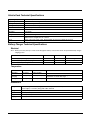
Marathon Specifications ..................................................................................................................12-1
Marathon Environmental Specifications ...........................................................................................12-1
Marathon Display Specifications ......................................................................................................12-2
Marathon AC/DC Adapter.................................................................................................................12-2
Marathon Extended Batteries (Optional) ..........................................................................................12-3
42Whr Extended Battery ............................................................................................................12-3
62Whr Extended Battery ............................................................................................................12-3
Marathon Pinouts .............................................................................................................................12-4
USB Connector ..........................................................................................................................12-4
Docking Connector.....................................................................................................................12-4
Desktop Dock Technical Specifications............................................................................................12-4
Vehicle Dock Technical Specifications .............................................................................................12-5
Battery Charger Technical Specifications.........................................................................................12-5
Electrical.....................................................................................................................................12-5
Temperature...............................................................................................................................12-5
Dimensions ................................................................................................................................12-5
Chapter 13 - Imager Add-On Module
Introduction .......................................................................................................................................13-1
Cautions and Warnings ....................................................................................................................13-1
How To Scan a Bar Code .................................................................................................................13-2
Scan a Linear Bar Code.............................................................................................................13-2
Scan a 2D Bar Code ..................................................................................................................13-2
Good Read / Bad Read Indicators....................................................................................................13-3
Factors That May Impact Decode Performance ...............................................................................13-3
Bar Code Quality........................................................................................................................13-3
Bar Code Source........................................................................................................................13-3
Bar Code Symbology .................................................................................................................13-3
Lens Damage.............................................................................................................................13-3
Ambient Lighting ........................................................................................................................13-3
Temperature...............................................................................................................................13-3
Bar Code Help............................................................................................................................13-4
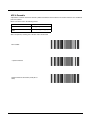
Printing Bar Codes ...........................................................................................................................13-4
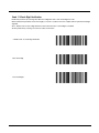
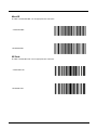
Miscellaneous Programmable Bar Codes ........................................................................................13-4
Beeper Frequency Adjustment...................................................................................................13-4
Beep on <BEL>..........................................................................................................................13-4
Event Reporting .........................................................................................................................13-4
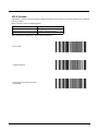
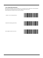
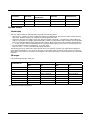
Return to Factory Default Settings ...................................................................................................13-4
Cleaning the Beam Aperture ............................................................................................................13-4
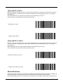
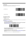
Programming the Symbol Imager .....................................................................................................13-5
Bar Code Decoder Types...........................................................................................................13-5
Pre-Configured Default Values .........................................................................................................13-6
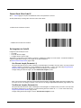
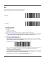
Set All Defaults / Cancel Bar Codes .................................................................................................13-9
Enable / Disable Parameter Scanning............................................................................................13-10
vi
Imager Parameters – General ........................................................................................................13-10
Beep After Good Decode .........................................................................................................13-10
Beeper Tone ............................................................................................................................13-11
Beeper Volume ........................................................................................................................13-12
Decode Aiming Pattern ............................................................................................................13-12
Decode Mirror Images (Data Matrix Only) ...............................................................................13-13
Decode Session Timeout .........................................................................................................13-13
Decoding Illumination...............................................................................................................13-14
Operational Mode.....................................................................................................................13-15
Picklist Mode ............................................................................................................................13-16
Power Mode .............................................................................................................................13-16
Presentation Mode Session Timeout .......................................................................................13-16
Report Version .........................................................................................................................13-17
Time Delay to Low Power Mode ..............................................................................................13-18
Event Reporting ..............................................................................................................................13-19
Decode Event...........................................................................................................................13-19
Boot Up Event ..........................................................................................................................13-20
Parameter Event ......................................................................................................................13-20
Miscellaneous Bar Code Reader Options ......................................................................................13-21
Prefix / Suffix Values ................................................................................................................13-21
Transmit “No Read” Message ..................................................................................................13-22
Scan Data Transmission Format..............................................................................................13-23
Transmit Code ID Character...........................................................................................................13-25
UPC/EAN........................................................................................................................................13-30
UPC-A ......................................................................................................................................13-30
UPC-E ......................................................................................................................................13-30
UPC-E1 ....................................................................................................................................13-31
EAN-8/JAN-8............................................................................................................................13-31
EAN-13/JAN-13........................................................................................................................13-32
Bookland EAN..........................................................................................................................13-32
Bookland ISBN Format ............................................................................................................13-33
Decode UPC/EAN/JAN Supplementals ...................................................................................13-34
UPC/EAN/JAN Supplemental Redundancy .............................................................................13-38
Transmit UPC-A Check Digit....................................................................................................13-38
Transmit UPC-E Check Digit....................................................................................................13-39
Transmit UPC-E1 Check Digit..................................................................................................13-39
UPC-A Preamble......................................................................................................................13-40
UPC-E Preamble......................................................................................................................13-41
UPC-E1 Preamble....................................................................................................................13-42
Convert UPC-E to UPC-A ........................................................................................................13-43
Convert UPC-E1 to UPC-A ......................................................................................................13-43
EAN-8/JAN-8 Extend ...............................................................................................................13-43
UCC Coupon Extended Code ..................................................................................................13-44
Code 128 ........................................................................................................................................13-45
UCC/EAN-128..........................................................................................................................13-45
ISBT-128 ..................................................................................................................................13-46
Code 39 .........................................................................................................................................13-47
Trioptic Code 39.......................................................................................................................13-47
Convert Code 39 to Code 32 ...................................................................................................13-48
Set Length(s) for Code 39........................................................................................................13-48
Code 39 Check Digit Verification .............................................................................................13-50
Transmit Code 39 Check Digit .................................................................................................13-50
Code 39 Full ASCII Conversion ...............................................................................................13-51
vii
Code 93 ..........................................................................................................................................13-52
Set Lengths for Code 93 ..........................................................................................................13-52
Code 11 ..........................................................................................................................................13-54
Set Lengths for Code 11 ..........................................................................................................13-54
Code 11 Check Digit Verification .............................................................................................13-56
Transmit Code 11 Check Digits ...............................................................................................13-57
Interleaved 2 of 5 (ITF) ...................................................................................................................13-58
Set Lengths for I 2 of 5.............................................................................................................13-58
I 2 of 5 Check Digit Verification ................................................................................................13-60
Transmit I 2 of 5 Check Digit....................................................................................................13-61
Convert I 2 of 5 to EAN 13 .......................................................................................................13-61
Codabar..........................................................................................................................................13-62
CLSI Editing .............................................................................................................................13-62
NOTIS Editing ..........................................................................................................................13-63
Set Lengths for Codabar ..........................................................................................................13-63
MSI .................................................................................................................................................13-65
Set Length(s) for MSI ...............................................................................................................13-65
MSI Check Digits......................................................................................................................13-67
Transmit MSI Check Digit ........................................................................................................13-67
MSI Check Digit Algorithm .......................................................................................................13-68
Postal Codes ..................................................................................................................................13-69
US Postnet ...............................................................................................................................13-69
US Planet .................................................................................................................................13-69
UK Postal .................................................................................................................................13-70
Japan Postal ............................................................................................................................13-71
Australian Postal ......................................................................................................................13-71
Dutch Postal.............................................................................................................................13-72
Transmit US Postal Check Digit...............................................................................................13-72
4 State Postal...........................................................................................................................13-73
GS1 DataBar (RSS) .......................................................................................................................13-74
GS1 DataBar Omnidirectional (RSS-14)..................................................................................13-74
GS1 DataBar Limited (RSS Limited)........................................................................................13-74
GS1 DataBar Expanded (RSS Expanded)...............................................................................13-75
Convert GS1 DataBar (RSS) to UPC/EAN ..............................................................................13-75
Composite ......................................................................................................................................13-76
Composite CC-C ......................................................................................................................13-76
Composite CC-A/B...................................................................................................................13-76
Composite TLC-39 ...................................................................................................................13-77
UPC Composite Mode .............................................................................................................13-78
UCC/EAN Code 128 Emulation Mode .....................................................................................13-79
Composite Beep Mode.............................................................................................................13-79
2D Symbologies .............................................................................................................................13-80
Aztec ........................................................................................................................................13-80
PDF417 ....................................................................................................................................13-80
MicroPDF417 ...........................................................................................................................13-81
Code 128 Emulation.................................................................................................................13-81
Data Matrix...............................................................................................................................13-82
Maxicode..................................................................................................................................13-82
MicroQR ...................................................................................................................................13-83
QR Code ..................................................................................................................................13-83
Imager Keypad Number Symbols...................................................................................................13-84
ASCII Character Equivalents ..........................................................................................................13-86
viii
Decode Zones ................................................................................................................................13-89
Introduction ..............................................................................................................................13-89
2D Imager ................................................................................................................................13-89
Chapter 14 - Customer Support
Technical Assistance ........................................................................................................................14-1
Product Service and Repair..............................................................................................................14-1
Limited Warranty ..............................................................................................................................14-1
ix
x
1
Marathon Agency Compliance
Marathon computers meet or exceed the requirements of all applicable standards organizations for safe operation. However, as
with any electrical equipment, the best way to ensure safe operation is to operate them according to the agency guidelines that
follow. Read these guidelines carefully before using your Marathon.
This documentation is relevant for the following model: Marathon Field Computer.
Caution:
!
RISK OF EXPLOSION IF BATTERY IS REPLACED BY AN INCORRECT TYPE. The battery should be disposed
of by a qualified recycler or hazardous materials handler. Do not incinerate the battery or dispose of the battery
with general waste materials.
Laser Warnings
Note: A 2D Imager Add-on module may be attached to the Marathon. Laser warnings and labels that follow are specifically for
a Marathon with a 2D Imager.
If the following label is attached to your product, it indicates the Marathon contains an engine with a laser aimer:
• Do not look into the laser’s lens.
• Do not stare directly into the laser beam.
• Do not remove the laser caution labels from the Marathon.
• Do not connect the laser bar code aperture to any other device. The laser bar code aperture is certified for use with the
Marathon only.
Caution:
!
Laser radiation when open. Please read the caution labels. Use of controls, adjustments or performance of
procedures other than those specified herein may result in hazardous radiation exposure.
Laser Label Location
If the following label is attached to your product, it indicates the
Marathon contains an engine with a laser aimer.
Laser Safety Statement
This device has been tested in accordance with and complies with IEC60825-1 ed2 (2007). Complies with 21 CFR 1040.10 and
1040.11, except for deviations pursuant to Laser Notice No. 50, dated June 24, 2007.
LASER LIGHT, DO NOT STARE INTO BEAM, CLASS 2 LASER PRODUCT, .0 mW MAX OUTPUT: 630-680nM.
Model Number, Serial Number and IMEI Labels
The model (item) number, serial number, and international mobile equipment identity (IMEI, if applicable) number for the
terminal are located on labels affixed to the back of the terminal.
1-1
FCC Part 15 Statement
This device complies with part 15 of the FCC Rules. Operation is subject to the following two conditions:
1. This device may not cause harmful interference.
2. This device must accept any interference received, including interference that may cause undesired operation.
This equipment has been tested and found to comply with the limits for a Class B digital device pursuant to part 15 of the FCC
Rules. These limits are designed to provide reasonable protection against harmful interference in a residential installation. This
equipment generates, uses, and can radiate radio frequency energy and, if not installed and used in accordance with the
instructions, may cause harmful interference to radio communications. However, there is no guarantee that interference will not
occur in a particular installation. If this equipment does cause harmful interference to radio or television reception, which can be
determined by turning the equipment off and on, the user is encouraged to try to correct the interference by one or more of the
following measures:
• Reorient or relocate the receiving antenna.
• Increase the separation between the equipment and receiver.
• Connect the equipment into an outlet on a circuit different from that to which the receiver is connected.
• Consult the dealer or an experienced radio or television technician for help.
If necessary, the user should consult the dealer or an experienced radio/television technician for additional suggestions. The
user may find the following booklet helpful: “Something About Interference.” This is available at FCC local regional offices.
Honeywell is not responsible for any radio or television interference caused by unauthorized modifications of this equipment or
the substitution or attachment of connecting cables and equipment other than those specified by Honeywell. The correction is
the responsibility of the user.
Caution: Any changes or modifications made to this equipment not expressly approved by Honeywell may void the FCC
authorization to operate this equipment.
FCC 5GHz Statement
LAN devices are restricted to indoor use only in the band 5150-5250 MHz. For the band 5600-5650 MHz, no operation is
permitted.
!
When using IEEE 802.11a wireless LAN, this product is restricted to indoor use, due to its operation in the 5.15- to 5.25GHz Frequency range.
The FCC requires this product to be used indoors for the frequency range of 5.15 GHz to 5.25 GHz to reduce the potential for
harmful interference to co-channel mobile satellite systems.
High-power radar is allocated as the primary user of the 5.25- to 5.35-GHz and 5.65- to 5.85-GHz bands.
These radar stations can cause interference with and/or damage to this device.
Canadian Compliance
This ISM device complies with Canadian RSS-210.
Operation is subject to the following conditions:
1. This device may not cause harmful interference.
2. This device must accept any interference received, including interference that may cause undesired operation.
This Class B digital apparatus complies with Canadian ICES-003.
1-2
CE Mark
The CE marking indicates compliance with the following directives:
• 1995/5/EC R&TTE
• 2011/65/EU RoHS (Recast)
In addition, complies to 2006/95/EC Low Voltage Directive, when shipped with recommended power supply. European contact:
Hand Held Products Europe BV
Nijverheidsweg 9-13
5627 BT Eindhoven
The Netherlands
Honeywell shall not be liable for use of our product with equipment (i.e., power supplies, personal computers, etc.) that is not CE
marked and does not comply with the Low Voltage Directive.
RF Notices
Warnings:
FCC/IC RF Radiation Exposure Statement:
1. This Transmitter has been demonstrated co–location compliance requirements with Bluetooth/WLAN antenna, FCC ID:
KDZLXE-FX1; IC: 1995B-LXEFX1 WWAN antenna, FCC ID: KDZLXE-FX1WW; IC: 1995B-FX1WW.
2. This equipment complies with FCC/IC RF radiation exposure limits set forth for an uncontrolled environment. This device
was tested for typical lap/hand held operations with the device contacted directly to the human body to the back, front, and
left side of the Handheld Computer.
To maintain compliance with FCC/IC RF exposure compliance requirements, avoid direct contact to the transmitting antenna
during transmission.
Bluetooth
Class II
Honeywell Scanning & Mobility Product Environmental Information
Refer to www.honeywellaidc.com/environmental for the RoHS / REACH / WEEE information.
Dealer License - Republic of Singapore
Vehicle Power Supply Connection Safety Statement
Vehicle Power Supply Connection: If the supply connection is made directly to the battery, a 10A slow-blow fuse should be
installed in the positive lead within 5 inches (12.7 cm) of the battery positive (+) terminal.
1-3
1-4
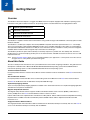
2
Getting Started
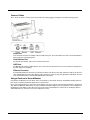
Overview
The Marathon hand held computer is a rugged, Ultra-Mobile Personal Computer equipped with a Windows operating system.
Information in this guide includes instruction for all operating systems. Procedure differences are highlighted as follows:
Icon
Operating System Instruction
Windows® 7 Professional
Windows® Embedded Standard
Windows® XP Professional
The Marathon is capable of wireless data communications using an 802.11a/b/g/n radio. Additional connectivity options include
Bluetooth and GPS.
The Marathon is a tablet-style computer with a 62-key QWERTY keyboard with number pad and features a 7.1" color display.
The touch screen display supports WVGA (800x480 resolution) and is available optimized for either indoor or outdoor lighting.
The keyboard is illuminated to facilitate use in dimly lit areas. A biometric mouse is included for security and screen navigation.
Available add on modules include a magnetic stripe card reader and a 2D imager.
The Marathon provides the power and functionality of a desktop computer in a portable unit. The desktop dock, much like a
docking port for a conventional laptop, provides ports for an external monitor and USB connections for devices such as a USB
keyboard and mouse.
Note: Contact Customer Support (page 14-1) for upgrade availability if your application or control panels are not the same as
the application or control panels presented in this guide.
About this Guide
This User’s Guide provides instruction for the system administrator to follow when configuring a Marathon. This guide has been
developed for a Marathon with a Microsoft® Windows® Embedded Standard operating system, Microsoft® Windows® 7
Professional operating system or a Microsoft® Windows® XP® Professional operating system.
Terminal Emulation Software
Honeywell provides RFTerm or Freefloat AccessOne for terminal emulation needs for the Marathon. Click here for the Freefloat
website.
Bar Code Decoder Software
Honeywell provides Freefloat Link*One for bar code decoding needs for the Marathon. Click here for the Freefloat website.
Click here for the Motorola web site SDK link for the Symbol 4400 2D Imager.
Keyboard Keymapping Software
There are many keyboard key-mapping applications available on the world wide web. There is no keyboard mapping application
available from Honeywell for the Marathon.
Magnetic Stripe Reader Software
The Magnetic Stripe Reader software supports the Microsoft Windows OLE for Point of Service (OPOS) / Unified Point of
Service (UPOS) driver. Click here to download Microsoft Point of Service for .NET.
POS for .NET is Microsoft’s implementation of UPOS for the .NET platform. POS for .NET is backward-compatible with existing
implementations of UPOS on the Microsoft Windows platform, OPOS. POS for .NET is implemented for Microsoft .NET
Framework v1.12.
Fingerprint Reader / Biometric Mouse
The Fingerprint Reader / Biometric Mouse SDK is available from the AuthenTec Developer Community web site. Click here for
access to the AuthenTec Developer Community web site SDK link.
2-1
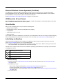
Microsoft Windows License Agreement (First Boot)
If your Marathon is shipped with a Microsoft Windows operating system, it may be necessary to complete the Windows
licensing/registration screens when starting the Marathon for the first time. To complete this information, you may need the
Microsoft Windows software/product key that is included with the Marathon.
See Microsoft Windows License Agreement (First Boot) (page 4-1) for instruction.
WWAN and the US and Canada
Use of the WWAN in the US and Canada requires a hip pad or a 62Whr extended battery. Removing the hip pad or extended
battery will disable the WWAN radio in the US and Canada.
Out of the Box
After you open the shipping carton verify it contains the following items:
• Marathon mobile computer
• Extended Battery (may be attached to the Marathon before shipping)
• Carrying Straps
• AC/DC Adapter (indoor use only)
• Quick Start Guide
If you ordered accessories for the Marathon, verify they are also included with the order. Be sure to keep the original packaging
in the event the Marathon should need to be returned for service. For details, see Product Service and Repair (page 14-1).
Initial Setup for Marathon
Following are steps you might take when setting up a new Marathon. Follow the links for further instruction for each step.
Contact Customer Support (page 14-1) if you need additional help.
Note: Installing or removing accessories should be performed on a clean, well-lit surface. When necessary, protect the work
surface, the Marathon, and components from electrostatic discharge.
Information in this chapter includes instruction for all Marathon operating systems. Differences in operating system instruction
are highlighted as follows:
Icon
Operating System Instruction
Windows® 7 Professional
Windows® Embedded Standard
Windows® XP Professional
Hardware Setup
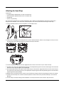
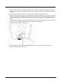
1. Install the hand strap, see Attaching the Hand Strap (page 2-9), and/or shoulder strap, see .Attaching the Shoulder
Strap (page 2-10).
2. Provide a power source:
• Attach a fully charged Extended battery, see Attaching an Extended Battery (page 5-1), or
• Connect a power cable, see Connecting an AC/DC Power Supply (page 2-11), or
• Place the Marathon in a powered desktop or vehicle mounted dock, see Desktop Dock and Powered Vehicle-Mount
Dock (page 11-1).
3. Press the Power key.
2-2
Software Setup
Note: Hardware setup should be completed before starting software setup.
1. Set Date and Time, see Setting Date and Time (page 2-12).
2. Set Power Management, see Setting Power Management (page 2-12).
3. Adjust Speaker Volume, see Setting Speaker Volume (page 2-12).
4. Setup Wireless client settings, see 802.11 Wireless Network Configuration (page 6-1).
5. Pair Bluetooth devices, see Connecting Bluetooth Devices (page 2-13).
2-3
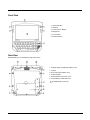
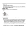
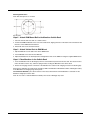
Front View
1. Status Indicators
2. Speakers
3. Touch Screen / Display
4. Microphone
5. Power Button
6. Biometric Mouse
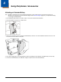
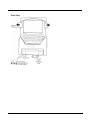
Rear View
Extended battery is not installed in image shown below.
1. Magnetic Stripe Card Reader Add-on Cover
2. Camera
3. Bar Code Imager Add-on Cover
4. Tethered Stylus
5. External Battery Connector Cover
6. Internal Battery / SIM Card Cover
Portability Strap Connection
2-4
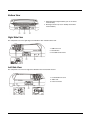
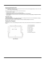
Bottom View
1. External Antenna Signal Pathway (for use in vehicle
mounted dock)
2. Docking Connector (for use in desktop and vehicle
mounted docks)
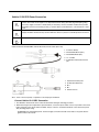
Right Side View
The components are on the right edge of the Marathon when viewed from the front.
1. USB Port Cover
2. Reset Button
3. Two USB 2.0 Host Ports
Left Side View
The components are on the left edge of the Marathon when viewed from the front.
1. Power/Audio Port Cover
2. Audio Jack
3. Power Connector
2-5
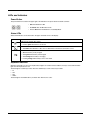
LEDs and Indicators
Power Button
The power button is located in the upper right of the Marathon. The power button is backlit as follows:
• Off when Marathon is Off.
• Solid blue when the Marathon is On.
• Flashes blue when the Marathon is in Standby Mode.
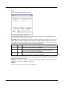
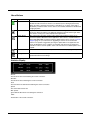
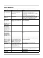
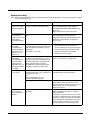
Status LEDs
Status LED indicators are located next to the upper left hand corner of the display.
Symbol
Function
Indicates the storage drive status:
• Flashes green when drive is accessed.
Indicates the wireless status:
• Solid blue when Marathon is On, does not blink when connection/re-connection occurs.
Indicates the battery status:
• Off when battery is fully charged.
• Solid green when battery is discharged.
• Solid orange when battery is charging.
• Flashing orange when battery is low or has failed.
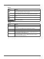
Keyboard Indicators
When the keyboard is not in use the keyboard back light is off. Under normal conditions, the keys are back-lit with white
light when the keyboard is in use.
The back light for certain keys is blue when the modifier key is active. These keys include:
• Fn
• CTL
• ALT
• SHIFT
The back light for the NUM LCK key is amber when Num Lock is active.
2-6
About the Battery
Charge or Recharge the Main Battery
Note: A new Marathon must be connected to an external power source to charge the internal main battery before first use.
The Marathon contains an internal Lithium Ion battery that, once fully charged, powers the Marathon for a minimum of 3
hours and 30 minutes (when the unit is not mounted in a powered dock or connected to an AC/DC adapter or extended battery).
An external power source is required before the main battery in the Marathon will recharge.
The main battery in the Marathon can be recharged using several different methods.
• by connecting the Marathon AC power adapter to the power jack on the Marathon, see Connecting an AC/DC Power
Supply (page 2-11).
• by docking the Marathon in a powered desktop dock, see Docking and Undocking (page 11-6).
• by docking the Marathon in a powered vehicle mounted dock, see Docking / Undocking (page 11-12).
• or by attaching a fully charged extended battery, see Attaching an Extended Battery (page 5-1).
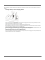
Charge or Recharge the Extended Battery
The Marathon Battery Charger is designed for an indoor, protected environment. New extended batteries must be fully
charged prior to use.
The extended battery can be recharged using two methods:
• By inserting the battery in a powered desktop dock spare battery charging bay.
• By inserting the battery in a Marathon Battery Charger charging bay.
2-7
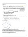
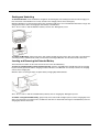
Tapping the Touch Screen with a Stylus
Note: Always use the point of the stylus for tapping or making strokes on the touch screen. Never use an actual pen, pencil, or
sharp/abrasive object to write on the touch screen.
Hold the stylus as if it were a pen or pencil. Touch an element on the screen with the tip of the stylus then remove the stylus from
the screen.
Firmly press the stylus into the stylus holder when the stylus is not in use.
Using a stylus is similar to moving the mouse pointer then left-clicking icons on a desktop computer screen.
Using the stylus to tap icons on the touch screen is the basic action that can:
• Open applications
• Choose menu commands
• Select options in dialog boxes or drop-down boxes
• Drag the slider in a scroll bar
• Select text by dragging the stylus across the text
• Place the cursor in a text box prior to typing in data
• Place the cursor in a text box prior to retrieving data using a scanner/imager or an input/output device connected to a serial
port.
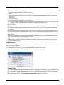
A right-click can be simulated by touching the touch screen with the stylus and holding it for a short time.
A right click is generated by tapping the mouse icon, usually located in the upper right hand corner of the screen.
After tapping, the mouse icon highlights the right button. The next touch screen tap is treated as a right click. The
mouse icon returns to the left button highlighted so subsequent taps are treated as left clicks.
If the mouse icon is not displayed, this feature can be enabled by tapping the PenMount icon in the System Tray.
From the menu that pops up, tap the Right Button to enable the mouse icon. When this option is enabled, a
checkmark is displayed in the menu.
The Biometric Mouse can be used instead of the touch screen. A stylus replacement kit is available.
Using the Biometric Mouse
The biometric mouse is located to the right of the keypad. Slide a finger over the biometric mouse to move the cursor in the
direction the finger moves.
Tapping the biometric mouse once generates a left-click, tapping twice rapidly generates a double-click.
Tapping the biometric mouse and holding generates a right-click.
If you are experiencing difficulties with the biometric mouse navigation, try varying the finger pressure on the biometric mouse.
The system administrator can disable the biometric mouse navigation function. See Navigation (page 3-5).
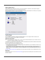
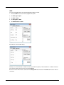
Adjusting Display Brightness
The display can be lightened or darkened by using the Fn key and the keypad:
1. Hold the Fn key down for a few seconds until the Fn key remains illuminated (sticky).
2. Press the 9 (brightness up) key to brighten the display.
3. Press the 3 (brightness down) key to darken the display.
The display brightness and darkness have nine levels. The display levels are managed by the Windows operating system. The
Fn key active sticky mode takes precedence if the NumLck key is illuminated (sticky) during this process.
2-8
Attaching the Hand Strap
Components:
• Long Hand Strap, approximately 7.4"/18.8 cm without loop
• Short Hand Strap, approximately 4.0"/10.2 cm without loop
• Strap Buckle
• Screws, strap attaching
The hand strap is designed to be used with the Marathon with or without an extended battery attached. The hand strap is
designed so the Marathon can be mounted in the desktop dock or the vehicle dock without removing the hand strap.
1. Place the Marathon with the screen facing down, on a flat stable surface.
2. Remove any of the plugs by unscrewing them in a counter-clockwise direction. Remove only the plugs necessary to mount
the hand strap. See the illustration below for possible hand strap orientations.
:
3. Insert the Strap Attaching Screws into the appropriate holes. These screws have an eye to attach the strap.
4. Thread the nylon loop of the Strap Buckle through one of the Strap Attaching Screws from the outside edge. Then thread the
buckle end of the strap through the loop and pull tight.
5. The hand strap kit contains two straps. Use the longer strap for a horizontal or diagonal mount and use the shorter strap for
the vertical mount. Thread the nylon loop of the appropriate strap through the other Strap Attaching Screw. Then thread the
strap through the loop and pull tight.
6. Making sure the closed loop fastener surface on the hand strap is facing up, slide the strap through the latch in the top clip.
7. Fold the end of the strap over so that the closed loop fastener surfaces mate evenly and the hand strap is secured to the
Marathon.
8. Test the strap's connection making sure the Marathon is securely connected to each end of the strap connectors.
2-9
Check the closed loop fastener and hand strap base connection frequently. If loose, they must be tightened or replaced before
the Marathon is placed into service again.
Attaching the Shoulder Strap
The shoulder strap is designed to be used with the Marathon with or without an extended battery attached. The shoulder strap
is designed so the Marathon can be mounted in the desktop dock or the vehicle dock without removing the shoulder strap.
1. Place the Marathon with the screen facing down, on a flat stable surface.
2. Remove the upper two of these plugs by unscrewing them in a counter-clockwise direction. Remove only the plugs
necessary to mount the strap.
3. Insert the Strap Attaching Screws into the upper two holes. These screws have an eye to attach the strap.
4. Thread the longer nylon loop of one of the Shoulder Strap Adapters through one of the Strap Attaching Screws. Then thread
the other end of the Shoulder Strap Adapter through the longer loop and pull tight. Repeat for the other Shoulder Strap
Adapter using the other Strap Attaching Screw.
5. Hook the swivel hooks on each end of the Shoulder Strap to the short loops on the adapters.
6. Adjust the shoulder strap length as desired. Adjust the pad on the shoulder strap so it rests comfortably on the shoulder.
2 - 10
Connecting USB Devices
The Marathon provides two Type A USB ports behind the access door on the right side of the device. USB devices may be
installed and removed or swapped without turning off the Marathon. When the USB ports are not in use, keep the port cover
door closed.
1. Open the port cover on the right side of the Marathon.
2. Plug the desired device, such as a USB mouse or storage device, or a USB tethered scanner into the USB port. Refer to
Start > Help and Support and the documentation for your USB device for more information.
The Marathon accepts only USB tethered scanners. The scanner is connected to one of the USB ports on the right side of the
Marathon.
If the tethered scanner does not have it's own power supply, e.g., installed rechargeable battery, the tethered scanner draws
power from the Marathon battery.
Connecting an AC/DC Power Supply
Note: The Honeywell-approved AC Power Supply and Adapter Cable are only intended for use in a 25ºC (77ºF) maximum
ambient temperature environment.
In North America, this unit is intended for use with power supply models FX1301PWRSPLY or FX1302PWRSPLY. The external
power supply may be connected to either a 120V, 60Hz supply or, outside North America, to a 230V, 50Hz supply, using the
appropriate detachable cordset. In all cases, connect to a properly grounded source of supply provided with maximum 15 Amp
overcurrent protection (10 Amp for 230V circuits).
1. Turn the Marathon off.
2. Connect the detachable cordset provided by Honeywell (US only, all others must provide their own cable) to the external
power supply (IEC 320 connector).
3. Plug the 3-prong end of the cordset into a grounded electrical supply receptacle (AC mains).
4. The LED on the AC adapter illuminates.
5. Open the port cover on the left side of the Marathon. When the power connector is not used, keep the port cover door
closed.
6. Plug the barrel end of the power cable into the Marathon.
7. The Marathon Battery Status LED at the upper left, next to the screen, illuminates orange to indicate the main battery is
recharging using power from the AC Adapter.
8. Turn the Marathon on.
2 - 11
Connecting an Audio Device
The Marathon provides an external headset connection via an audio jack connector under the left-side port cover. When the
audio port is not in use, keep the port cover door closed.
1. Open the left-side port cover.
2. Insert the speaker or headphone plug into the audio connector; making sure the plug is firmly seated in the jack.
Software Configuration Options
Many configuration options are available in the Microsoft Windows Control panels. For additional information, refer to Help and
Support on the Start menu for configuration details.
Setting Date and Time
Use the windows interface to set date, time and time zone. Tap the time displayed in the task bar or tap:
Start > Control Panel > Clock, Language and Region > Date and Time (Category view)
Start > Settings > Control Panel > Date and Time (Classic view), or tap
Start > Settings > Control Panel > Date, Time, Language and Regional Options > Change the Date
and Time (Category view)
Setting Power Management
Use the Windows interface to set power management options. Tap the battery icon in the task bar or tap:
Start > Control Panel > Hardware and Sound > Power Options (Category view)
Start > Settings > Control Panel > Power Options (Classic view), or tap
Start > Settings > Control Panel > Performance and Maintenance > Power Options (Category view)
Setting Speaker Volume
Use the Windows interface to control speaker volume. Tap the speaker icon in the task bar or tap:
Start > Control Panel > Hardware and Sound > Sound (Category view)
Start > Control Panel > Sound (Classic view)
Start > Settings > Control Panel > Sound and Audio Devices > Sounds (Classic view), or tap
Start > Settings > Control Panel > Sounds, Speech and Audio Devices > Adjust the System Volume
(Category view)
2 - 12
Connecting Bluetooth Devices
Use the Windows interface to manage Bluetooth devices. Tap the Bluetooth icon in the task bar, if it exists, or:
Tap the Bluetooth icon in the task bar, if it exists.
Start > Settings > Control Panel > Bluetooth Devices (Classic view), or tap
Start > Settings > Control Panel > Printers and Other Hardware > Bluetooth Devices (Category view)
Restart/Shutdown
Use the Windows interface to restart or shut down the Marathon.
• Tap Start > Shut Down > Restart
• Tap Start > Shut Down > Shut down
Calibrating the Touch Screen
To calibrate the touch screen, tap Start > Programs > PenMount Universal Driver > Utility > PenMount Control Panel.
Select PenMount 6000 USB and then tap Configure. Select Standard Calibration or Advance Calibration.
Advanced Calibration allows the user to select the number of calibration points. With either option, follow the on screen
instructions to touch the red square, hold the touch and then lift the stylus to complete the calibration process.
On-Screen Keyboard
Windows 7 Professional only.
Single Use
To enable the on-screen keyboard for the current session, select Start > Control Panel > Ease of Access Center, click Use
On-Screen Keyboard. The on-screen keyboard is available immediately. It is not available after a reboot.
Persistent Use
To enable the on-screen keyboard upon every reboot, select Start > Control Panel > Ease of Access Center, click Use the
computer without a mouse or keyboard. Enable (check) Use On-Screen Keyboard. Click Apply. The on-screen keyboard is
available immediately. The on-screen keyboard is displayed upon every reboot. Click the task bar keyboard icon to minimize the
keyboard until needed.
To disable the On-Screen Keyboard, select Start > Control Panel > Ease of Access Center. Click Use the computer without
a mouse or keyboard. Disable (uncheck) Use On-Screen Keyboard. Click Apply.
Data Entry
You can enter data into the Marathon through several different methods. Manual data entry methods include the keyboard and
touch screen. Automated data entry methods include the imager module, a wireless Bluetooth scanner, a tethered USB scanner
and the magnetic card reader module.
Keyboard Data Entry
Refer to KeyMaps (page 9-1) for 101-key keyboard equivalent key presses.
The 62-key keyboard with number pad is used to manually input data that is not collected otherwise. Almost any function
that a full sized computer keyboard can provide is duplicated on the keyboard but it may take a few more keystrokes to
accomplish a keyed task.
When using the keyboard, some keys have multiple functions. The primary alpha or numeric character is printed on the key.
Bar Code Data Entry
The Marathon supports an accessory imager module for bar code label reading, as well as optional equipment such as a
wireless Bluetooth bar code scanner and a tethered USB scanner.
Keyboard data entries can be mixed with bar code data entries.
2 - 13
Magnetic Card Data Entry
The Marathon supports an accessory magnetic card reading module. Keyboard data entries can be mixed with magnetic
card data reader entries.
Touch Screen Data Entry
Note: If the touch screen is not accepting pen touches, the touch screen should be re-calibrated. See Calibrating the Touch
Screen (page 2-13).
Note: Always use the point of the stylus for tapping or making strokes on the display. Never use an actual pen, pencil or
sharp object to write on the touch screen.
The touch screen can be used in conjunction with the keyboard and a bar code decoder.
• Touch the stylus to the field of the data entry form to receive the next data feed.
• The cursor begins to flash in the field.
• The Marathon is ready to accept data from either the keyboard, the accessory imager, a wireless Bluetooth device or a
device connected to a serial port on a powered dock.
Note: The touch screen may be disabled. See Disabling the Touch Screen (page 3-6).
2 - 14
3
Hardware Configuration
Processor, Memory and Storage
The Marathon has an Intel® Atom Z530 (1.6GHz) processor. System memory is 1 GB or 2 GB DDR2 SDRAM. Storage is
supplied by an internal solid state hard drive (8, 16, 32 or 64GB).
Display
A 7.1" WVGA (800x480) display is installed. The display includes a touch screen. Depending on the option ordered, the display
is optimized for either indoor or outdoor ambient lighting. An Intel® controller is provided for the display. The controller is capable
of supporting a second display when the Marathon is docked in a desktop dock with an external display attached to the
VGA port on the dock.
Audio
The Marathon contains two integrated speakers and an integrated microphone. An audio connector is available for an external
headset.
Wireless Communication
The following options are available:
• 802.11 WLAN radio
• Bluetooth
• WWAN
• GPS
Several wireless devices may be installed in the Marathon. The available devices and combinations may vary by regulatory
domain. Available devices include:
• An 802.11 radio. See 802.11 Wireless Network Configuration (page 6-1).
• A Bluetooth radio. See Bluetooth Configuration (page 7-1).
• A WAN card. See OneClick Internet Wireless Configuration (page 8-1).
Power Management
The Marathon uses Microsoft Windows Power Management. The Marathon has two operating modes: Normal and Standby.
In Normal operating mode all systems are powered up and the video display is on. However, Microsoft Windows also allows the
display and hard disks to be shut down in normal mode to conserve energy.
The Standby mode shuts down many devices such as the display and hard drives. For complete details on the standby mode,
refer to the Microsoft Help and Support (Start > Help and Support).
Power Input / Main Battery
The Marathon is powered by a main battery (Lithium Ion rechargeable 2200 mAh) concealed inside the Marathon case, that
provides 3.5 hours of operation without a recharge. The main battery can be recharged using external power sources, such as
an indoor AC/DC adapter connected directly to the Marathon. The main battery remains concealed in the Marathon while
charging. The main battery will also recharge when the Marathon is docked in a powered desktop dock or vehicle dock. With an
attached fully charged extended battery, Marathon battery life is increased to 6 or 10 hours based on the extended battery
selected. The main battery and an attached extended battery are recharged whenever the Marathon is:
• connected to an AC power adapter.
• placed in a powered desktop dock.
• placed in a powered vehicle dock.
When AC power is disconnected from a Marathon with an attached extended battery, operating power is drawn from the
extended battery until it is depleted, then from the main battery.
3-1
Backup Battery
The Marathon has a permanent lithium battery installed to maintain time, date and BIOS setup information. The backup battery
is not user serviceable and should last five years with normal use before it requires replacement. The lithium backup battery
should only be exchanged by authorized service personnel.
Power Button
The Power (on/off) button is a push button located on the upper right corner of the Marathon. If the Marathon is Off, pressing the
power button turns the Marathon On.
If the Marathon is On, Windows determines the results of a power button press based on user configuration. For example, the
Marathon may be configured to:
• Shut down.
• Hibernate.
• Ignore the power button press.
• Ask user to choose.
Power button behavior is configured by selecting:
Icon
Configuration Path
Start > Settings > Control Panel > Power Options > Advanced
Start > Control Panel > Power Options > Advanced
Pressing and holding the power switch for several seconds forces a shutdown.
The Marathon is designed for a controlled shutdown when using the power button. A controlled shutdown first closes any open
programs, and then shuts down the Windows operating system. When the main battery is discharged, DO NOT remove external
power from the Marathon without first shutting down the Marathon.
The Marathon shutdown may be initiated in any of the following ways:
• Selecting the Shutdown option from the Windows Start Menu.
• Selecting the Shutdown option from the Windows Task Manager. The Windows Task Manager is opened by pressing CtrlAlt-Del and clicking the Task Manager button.
• Momentarily pressing and releasing the power button. The Marathon behavior when the power button is pressed can be
configured in the Power Options control panel.
• Pressing and holding the power button for approximately five seconds. Any open programs and the Windows operating
system are shut down before power off. Note that this option must be used to shut down when the operating system is not
responding.
For more information on the Windows shutdown process, refer to Help and Support on the Windows Start menu or commercially
available Windows guides.
Reset Button
Use with caution. The Reset button is on the right side (display facing up) of the Marathon. Press the Reset button in with the tip
of the stylus and the Marathon immediately disconnects all power sources. The Marathon turns Off (uncontrolled shutdown).
3-2
External Connectors
The following external connectors are located on the Marathon:
• Two USB 2.0 Host ports.
• External power supply connector.
• Audio connector is a 3.5 mm jack for a headset.
• Docking connector on bottom for use with vehicle mounted dock or desktop dock.
• External antenna signal pathways on bottom for use with vehicle mounted dock.
• COM 1 is accessible when docked in a vehicle mounted or desktop dock.
• COM 2 is reserved for add-on modules (imager or magnetic card reader).
USB Connectors
There are two USB 2.0 Host ports, located on the right side (display facing up) and protected by a sliding cover.
Audio Connector
The Audio connector is a standard 3.5mm connector for an external headset, located on the left side (display facing up) and
protected by a sliding cover.
Power Supply Connector
The power connector is a barrel style connector, located on the left side (display facing up) and protected by a sliding cover.
AC/DC power is supplied to the Marathon through the power connector.
The Marathon power supply connector accepts DC input voltage at 19 Volts.
Antenna Signal Pathway
The external GPS and WWAN antenna signal pathways are located on the bottom of the Marathon. The antenna signals
originate from the external GPS and WWAN antenna connectors on the vehicle dock. No physical antenna connects
directly to these ports on the Marathon.
Docking Connector
The docking connector is located on the bottom of the Marathon. The connector interfaces with the matching connector in
the Marathon desktop and vehicle mounted dock, allowing the Marathon to interface with USB, serial or other ports present
on the selected dock.
Keyboard
The keyboard has 62 keys, including a number pad. A biometric mouse is located to the right of the keyboard. When using the
keyboard, some keys have multiple functions. The primary alpha or numeric character is printed on the key.
See KeyMaps (page 9-1) for 101-key keyboard equivalent key presses.
Backlighting
• Keys have a dark grey background with frosted white characters for visibility with the backlight on or off.
• Keys are backlit with a white light, except for sticky keys (see below) that have a different backlight color when the key is
active.
Sticky Keys
Alt, Ctl, Shift, Fn and Num Lck are sticky keys and function as described below:
• Press key once and key stays sticky for next keystroke.
• Press key and hold for a second and a half and the key stays sticky until sticky key is pressed again. For example, press
Num Lck once and Num Lck stays ON, press it again and it turns OFF.
Sticky Key Indicators
• Num Lck: Amber backlight indicates sticky key is active.
• Alt, Ctl, Shift, Fn: Blue backlight indicates sticky key is active.
3-3
Keyboard Help
Localized operating systems and the keyboard:
Marathon operating systems are available in German, French, Spanish, etc. If using a localized operating system, view the
Region and Language control panel to verify English (United States) has been chosen as the primary keyboard language.
The on-screen keyboard will display the operating system's localized language symbols and can be used as an alternative
for the physical keyboard on the Marathon if preferred.
Biometric Mouse
The Marathon contains a biometric mouse located on the right next to the keypad.
The biometric mouse performs two functions, security and screen navigation (simulating a mouse). Use the F9 function key to
toggle between the two features.
Security Features
As a security device, the biometric mouse can restrict device access to only those users whose fingerprint scan is stored on
the Marathon. Examples include:
• Windows logon can be performed with a fingerprint scan as opposed to the traditional user name and password. You
must create a Windows user account with a password, then shutdown and restart the Marathon before you can add
fingerprint security to that user account. After rebooting, create fingerprint security, then shutdown and restart the
Marathon to save the password in the registry.
• Internet Explorer web site login information (user name and password) can be stored and accessed only after a
successful fingerprint scan.
• SecureLock, a part of the Fingerprint software package, can be used to create a virtual disk that can only be accessed
after a successful fingerprint scan. Without an authorized fingerprint scan, the drive is not accessible or displayed in
Windows explorer.
• Files and folders may be assigned encryption that limits access to only those users who have a stored fingerprint.
For information on using the finger print security feature, select Start > Programs > Fingerprint Software > Help.
3-4
Fingerprint Reader / Biometric Mouse
The Fingerprint Reader / Biometric Mouse SDK is available from the AuthenTec Developer Community web site.
Click here to access the AuthenTec Developer Community web sites SDK link.
Navigation
By default, the biometric mouse is enabled for cursor navigation. Sliding a finger over the biometric mouse moves the cursor in the same direction the finger moves. The sensitivity (motion speed) may be adjusted or the feature disabled.
Tapping a finger on the biometric mouse is treated as a mouse left-click. Two taps in quick succession is treated as a double-tap. Tapping and holding is treated as a right-click.
Follow this procedure to turn off Biometric Mouse navigation.
1. Move the cursor focus to the TruPrint icon in the System Tray.
2. Right-click the TruPrint icon using the stylus.
3. Select Settings from the pop-up menu.
4. Click the No Nav radio button.
5. Click Apply.
6. Click OK.
7. Reboot and Biometric Mouse navigation is disabled.
If you prefer to toggle between modes, then without rebooting press the F9 function key to turn Biometric Mouse navigation on and off.
When Biometric Mouse navigation is turned off, use an external mouse cabled to a USB port to navigate.
Follow this procedure to turn on Biometric Mouse navigation after rebooting.
1. Move the cursor focus to the TruPrint icon in the System Tray.
2. Right-click the TruPrint icon using the stylus.
3. Select Settings from the pop-up menu.
4. Click the Cursor Nav radio button.
5. Click Apply.
6. Click OK.
7. Reboot and Biometric Mouse navigation is enabled.
3-5
Touch Screen
Calibrating the Touch Screen
Although the Marathon touch screen is installed and calibrated before the Marathon is shipped, users may make adjustments to the calibration. To calibrate the touch screen, select Start > Programs > PenMount Universal Driver > Utility >
PenMount Control Panel. On the Device tab, double-click the PenMount 6000 USB icon. On the Calibrate tab, tap either
the Standard Calibration or the Advanced Calibration button.
Advanced Calibration uses more calibration points than the Standard Calibration option.
Follow the instructions on the screen. The calibration utility displays a red square on the screen. Touch the center of the
square with the stylus and hold for a few seconds. Release and repeat with the next square. After all locations have been
touched, the calibration utility saves the settings and automatically closes.
If no input is received, the calibration utility times out. Press the ESC button to exit the calibration utility without saving any
changes.
Refresh the Touch Screen Calibration Points
Select Start > Programs > PenMount Universal Driver > Utility > PenMount Control Panel. On the Device panel, single-click the PenMount 6000 USB icon. Click the Refresh button. The touch screen is refreshed immediately. Click OK to
close the control panel.
Note: If when using the Intel Ultra Mobile GMA Driver and rotating the screen, the touch screen will require re-calibration
for the rotated screen touch areas. Connect and use a USB mouse, instead of screen touch, to access the control
panels needed for re-calibration.
Disabling the Touch Screen
If desired, the touch screen can be disabled in the Windows control panel. Once disabled, the touch screen remains disabled until it is enabled again.
To disable the touch screen, access the Windows control panel and click on System > Hardware > Device Manager >
Mice and other pointing devices. There is a listing for PenMount USB Mouse. Right click on this listing and select Disable
from the Device Usage menu.
To enable the touch screen, follow the same process, selecting Enable from the right click menu.
Using a Dock and a Second Monitor
Pre-requisite: The Marathon is in the Dock, and a second monitor is attached to the dock. The Marathon display driver has
been setup to extend the Marathon display to the second monitor.
Use a connected USB mouse to select items on the displays. The mouse can be connected to the Marathon or the desktop
dock.
When the Marathon display driver is setup to extend the Marathon display to the second monitor, cursor calibration on the
Marathon touch display is offset. Do not use the touch panel on the Marathon to select items on the Marathon display.
When a cabled USB mouse is used, the touch screen calibration is correct.
3-6
The Display
The Marathon display is capable of supporting WVGA graphics modes (800x480). The display covering is designed to resist
stains. The touch screen allows signature capture and touch input. A display optimized for outdoor viewing is available.
The touch screen is a Resistive Panel with a scratch resistant finish that can detect touches by a stylus, and translate them into
computer commands. In effect, it simulates a computer mouse. Only Delrin or plastic styluses should be used. An extra or
replacement stylus may be ordered.
Note: Always use the point of the stylus for tapping or making strokes on the display. Never use an actual pen, pencil or sharp
object to write on the touch screen.
Adjust Display Brightness
The display can be lightened or darkened by using the Fn key and the keypad:
1. Hold the Fn key down for a few seconds until the Fn key remains illuminated (sticky).
2. Press the 9 (brightness up) key to brighten the display.
3. Press the 3 (brightness down) key to darken the display.
The display brightness and darkness have nine levels. The display levels are managed by the Windows operating system.
The Fn key active sticky mode takes precedence if the NumLck key is illuminated (sticky) during this process.
Cleaning the Display
Keep fingers and rough or sharp objects away from the display. If the glass becomes soiled or smudged, clean only with a
standard household cleaner such as Windex® without vinegar or use Isopropyl Alcohol. Do not use paper towels or harshchemical-based cleaning fluids since they may result in damage to the glass surface. Use a clean, damp, lint-free cloth. Do
not scrub optical surfaces. If possible, clean only those areas which are soiled. Lint/particulates can be removed with clean,
filtered canned air.
3-7
3-8
4
Software Configuration
Introduction
Like any personal computer, there are many aspects to the setup and configuration of the Marathon. Much of the setup and
configuration of the Marathon is dependent upon the optional features (both hardware and software) installed on the computer.
Since the Marathon uses the Microsoft Windows Plug and Play operating system, much of the hardware setup is automatic. The
examples found in this section are to be used as samples only; as the configuration of your specific computer may vary. The
following sections provide a general reference for the configuration of the Marathon and its optional features.
Refer to commercially available Microsoft Windows user guides or to Windows on-line Help applications for more information on
system configuration.
Operating System
The Marathon is available with the following Windows operating systems:
• Windows® XP Professional
• Windows® Embedded Standard
• Windows® 7 Professional)
The Marathon supports only one operating system at a time.
Microsoft Windows Setup and Configuration
After the system files are processed, Microsoft Windows begins to load. Windows maintains a System Registry and INI files.
Standard Windows configuration options apply to the Marathon. Configuration options are located in either the System Tray or
Notification bar or the Control Panel:
• The System Tray or Notification bar contains icons for adjusting the time, date or volume level.
• The Control Panel contains icons for many other configuration options, such as Power Management, Regional and Language
Options, etc.
• The Control Panel icons are also used to add, delete or modify software installed on the .
Refer to Help and Support on the Windows Start menu or commercially available Windows guides for more information on
configuration options in Windows.
Microsoft Windows License Agreement (First Boot)
If your Marathon is shipped with a Microsoft Windows operating system pre-installed, it is necessary to complete the Windows licensing/registration screens when starting the Marathon for the first time. To complete this information, you may
need the Microsoft Windows software key that was included with the Marathon.
When Microsoft Windows is started by the user for the first time (known as the “out of the box experience”), a series of
questions is presented. If prompted, the product key (printed on a decal attached to the Marathon) must be entered. The
series of prompts and responses allow the user to configure Microsoft Windows operating system on the Marathon according to user needs.
Proceed with the remainder of the boot process.
Drive C Folder Structure
Microsoft Windows is installed in the \Windows folder. In addition, Microsoft Windows creates other folders and several subfolders. For more information on the folder structure, refer to commercially available Microsoft Windows OS reference
guides.
4-1
Software Loaded on Drive C
The software loaded on the Marathon computer consists of:
• BIOS
• Microsoft operating system (Windows XP Professional or Windows Embedded Standard or Windows 7 Professional)
• device drivers
• radio software
• touch screen software
The software installed on the Marathon is summarized below.
Note: Due to the complex folder structure and System Registry under Microsoft Windows, software should not be removed
manually. Instead use the Add or Remove Programs icon in the Windows Control Panel.
Microsoft Windows
Microsoft Windows is installed in the \Windows subfolder, which is the Windows default. In addition, Windows places files in
other folders and subfolders during installation. For more information, refer to commercially available Microsoft Windows
OS user guides.
Device Drivers
Device drivers are installed for all installed hardware options, such as the display, touch screen, radios, Ethernet port, etc.
For more information on Microsoft Windows device drivers, refer to commercially available Windows operating system reference guides.
Radio Software
The Marathon is delivered with the radio software installed. Because the Marathon uses a Microsoft Windows operating
system, the radio installation includes Windows device drivers.
Touch Screen Software
PenMount Universal software is installed for calibrating the Marathon’s touch screen. See Calibrating the Touch Screen
(page 3-6) for more information.
Control Panel
Most control panels on the Marathon are standard Microsoft Windows items. For help and information on the standard control
panels, refer to Help and Support.
The panels listed below may differ from a standard Microsoft Windows equipped PC or laptop.
System Info Panel
Display Panel
This is a standard Microsoft Windows control panel applet. On the Settings tab, two displays are supported. By default, display #1 is the Marathon's built in WVGA display. Display #2 is an external display connected to the VGA port on the Marathon desktop dock.
When setting up dual monitors, use Intel UltraMobile GMA Monitor (located in Control Panel).
4-2
Power Options Panel
Power schemes can be configured that will be in effect when the Marathon is attached to an external power supply or
docked in a powered dock as well as when running on battery power.
On the Power Meter tab, battery #1 refers to the main battery concealed inside the Marathon case. Battery #2 is an optional
extended battery that connects to the back of the Marathon.
TruePrint Panel
Use the TruePrint control panel to configure the fingerprint module for screen navigation. Motion sensitivity can be
adjusted and the fingerprint module navigation can be disabled.
User Accounts Panel
Note: The following applies to a Marathon that is not part of a domain. When the Marathon is part of a domain, the user is
prompted for credentials at Windows startup or log on.
The Marathon is preconfigured with an administrator account named Administrator. By default, the Marathon automatically
logs onto the Administrator account at Windows startup.
If the user assigns a password to the Administrator account:,
• The password is stored and used when the Marathon logs onto the Administrator account at Windows startup. The user
is not prompted to enter a password.
• If the user logs off, the password must be manually entered to log back onto the Marathon. At this time, the user could
specify a different user account (and password, if necessary) to log on, if this user account has been added to the
Marathon. However, when the Marathon is restarted, the Administrator account would automatically become the active
user account.
If Using the Windows Certificate Store (page 6-54), the user must assign a password to the active (Administrator) account.
Wi-Fi Icon
The Wi-Fi icon provides access to the Summit Client Utility (page 6-37) where the default profile can be edited for use with
the wireless network.
4-3
Network Configuration
There are several networking options available for the Marathon.
802.11 Wireless Radios
Refer to the instructions for configuring the 802.11 radio in Summit Wireless Network Configuration (page 6-36).
Ethernet Connector
A wired Ethernet connection is only available when the Marathon is docked in a desktop dock. See Desktop Dock (page 111) for more information.
For more information on configuring the Microsoft Windows network settings, refer to Help and Support on the Windows
Start menu or commercially available Windows networking literature.
GPS (Optional)
When the GPS module is factory installed in the Marathon, based on the current Marathon configuration the GPS module
will use COM 5 on the Marathon to retrieve latitude (the location north or south of the equator in degrees) and longitude
(the angular distance from the Prime Meridian in degrees).
To verify COM port settings follow this path: Start > Settings > Control Panel > System > Hardware > Device Manager >
Ports (COM / LPT).
WWAN
Refer to the section on Using OneClick Internet (page 8-5) and Install SIM Card (page 8-2).
Bluetooth
Refer to the section on configuring the Bluetooth radio. See Bluetooth Configuration (page 7-1).
4-4
5
Using Peripherals / Accessories
Attaching an Extended Battery
Note: Installing or removing accessories should be performed on a clean, well-lit surface. Protect the work surface, the
Marathon, and components from electrostatic discharge. Contact Customer Support (page 14-1) for help when attaching
or removing an extended battery.
1. Turn the Marathon Off. Remove any cables, straps or accessories attached to the Marathon.
2. Place the Marathon face down on a stable surface.
3. Remove the 2 mounting screws securing the extended battery connector cover to the Marathon and remove the cover. Put
the screws and cover aside in a safe place.
4. Line up the charging pins on the extended battery with the charging pins in the Marathon extended battery connector bay.
5. Connect the extended battery to the Marathon using the captive screws in the extended battery.
5-1
6. Re-attach accessories, if any.
7. Turn the Marathon on.
The Marathon is ready for use.
Remove the extended battery from the Marathon when preparing to recharge the extended battery in a powered desktop dock
or in a Marathon battery charger. Up to four extended batteries can be charged simultaneously in the battery charger.
Honeywell recommends, when the Marathon will not have an extended battery attached, that the extended battery connector
cover is in place, protecting the Marathon extended battery connector opening.
5-2
Installing a SIM Card
Note: Installing or removing accessories should be performed on a clean, well-lit surface. Protect the work surface, the
Marathon, and components from electrostatic discharge. Contact Customer Support (page 14-1) for help when installing
or removing a SIM card.
1. Turn the Marathon off.
2. Place the Marathon face down on a stable surface.
3. Remove the 4 mounting screws securing the battery cover to the Marathon and remove the battery cover. Put the screws
aside in a safe place.
4. Lift the battery using the pull strap and move it aside. Do not disconnect the battery.
5. Push the SIM card holder up (in the direction of the word OPEN on the holder) to release the lock.
6. Carefully lift the SIM card holder up. Do not remove the SIM card holder.
7. Slide a SIM card into the slot using the guides on the inside of the slot. Do not remove the SIM card holder.
8. The angled corner of the SIM card ensures that the card fits the correct way in the slot.
9. Lower the holder, containing the SIM card, into the opening.
10. Slide the SIM card holder down (in the direction of the word LOCK on the holder) to lock the SIM card flat in the opening
(LOCK).
11. Replace the battery in the battery well.
12. Replace the battery cover, securing it with the original 4 screws.
5-3
Replacing the Main Battery
Note: Installing or removing accessories should be performed on a clean, well-lit surface. Protect the work surface, the
Marathon, and components from electrostatic discharge. Contact Customer Support (page 14-1) for help when installing
or removing a main battery.
1. Turn the Marathon Off. Remove any cables or accessories attached to the Marathon.
2. Place the Marathon face down on a stable surface.
3. Remove the 4 mounting screws securing the battery cover to the Marathon and remove the battery cover. Put the screws
aside in a safe place, i.e., where they can't get knocked off the table and onto the carpet and lost forever in the grey and
black pattern.
4. Lift the battery using the pull strap.
5. Hold the battery out of the way and carefully separate the Marathon plug (on the right) from the plug cabled to the main
battery. Do not bend the pins.
6. Connect the new battery cabled plug to the plug on the Marathon.
7. Lower the connected battery into the battery well using the pull strap.
8. Replace the battery cover, securing it with the original 4 screws.
9. Connect the Marathon to an external power source. The main battery will be fully charged in 2 hours.
5-4
The Marathon is ready for use.
Li-Ion Battery
When disposing of the lithium-ion battery, the following precautions should be observed: The battery should be disposed of
properly. The battery should not be disassembled or crushed. The battery should not be heated above 212°F (100°C) or
incinerated.
!
CAUTION - RISK OF EXPLOSION IF BATTERY IS REPLACED BY AN INCORRECT TYPE.
DISPOSE OF USED BATTERIES ACCORDING TO THE INSTRUCTIONS.
5-5
Bar Code Readers
The Marathon can use the following external bar code readers:
• Tethered hand-held scanners are tethered to a USB port on the Marathon or a serial port on the Marathon dock and are
configured by scanning the engine-specific bar codes in the scanner manufacturer's programming guide. The manufacturer's
guides are usually shipped with the bar code reader.
• Wireless hand-held Bluetooth scanners are configured by scanning the engine-specific bar codes in the scanner
manufacturer's programming guide. The manufacturer's guides are usually shipped with the bar code reader.
• The body worn Bluetooth Ring Scanner module may be using a Symbol 4400 Ring Imager or a Symbol 955 Ring Scanner.
The Bluetooth Ring Scanner module is configured by scanning the bar codes in the Bluetooth Ring Scanner User’s Guide.
2D Imager
The 2D Imager is pre-attached. The optional 2D Imager (bar code decoder) is attached to the top right hand area of the
Marathon (when the display is visible). When present, the 2D Imager uses COM2.
When Freefloat Link*One is installed, and the user wishes to decode a bar code using the 2D imager, the NumLock key must be
highlighted. Then to scan a bar code, aim the Imager scan aperture at the bar code and press the minus (-) key on the numeric
keypad. The minus key is the default hotkey for the Imager / Link*One combination.
The 2D Imager engine can be programmed using the bar codes in Imager Add-On Module (page 13-1).
Magnetic Stripe Reader
The Magnetic Stripe Reader is pre-attached. The optional Magnetic Stripe Reader (MSR) is attached to the top left hand area of
the Marathon (when the display is visible). When present, the Magnetic Stripe Reader uses COM3 and supports Microsoft
OPOS/JPOS.
The user will need to create a company-specific magnetic stripe reader Point of Sale (POS) application.
Notes:
• The Marathon must be awake and ready to receive scanned card data before swiping a card through the Magnetic Stripe
Reader slot.
• Magnetic Stripe Reader use does not prevent the display from turning on or off, or the Marathon from entering or resuming
from Standby mode.
• Power scheme timers are not affected by Magnetic Stripe Reader functions.
5-6
Loading an Operating System on the Marathon
If it becomes necessary to reload the Marathon operating system, two options are available.
1. A recovery DVD from Honeywell. The recovery DVD is customized for the type of hard drive and operating system installed
in the Marathon.
2. A user provided operating system. The user must:
• Provide their own installation source of a supported operating system (such as Windows 7).
• Have a valid activation key for that operating system.
Contact Customer Support (page 14-1) for information on the Marathon Recovery DVD and the Drivers CD ROM.
The Marathon Drivers CD-ROM
Contact Customer Support (page 14-1) to get the latest Marathon drivers CD ROM.
The Marathon Drivers CD-ROM contains files that may be necessary when configuring the Marathon. It is recommended
that the device drivers CD be available during Microsoft Windows installation and configuration. Since the Marathon does
not have a CD-ROM drive, the device drivers can be copied to a USB jump drive or accessed via a USB CD drive. The
device drivers can also be copied to a location on the network if a network connection is used to install the Windows OS.
After Microsoft Windows is installed, device drivers contained on the CD can be used to update default Windows device
drivers, if necessary.
For more information on installing or updating Microsoft Windows device drivers, refer to Help and Support on the Windows
Start menu or commercially available Windows documentation.
Using the Recovery DVD
Contact Customer Support (page 14-1) to get the latest updates before performing the procedures that follow.
The Recovery DVD is a method to restore the software on your Marathon to the same state it had when it was shipped from
the factory. When the Recovery DVD is used on your Marathon, it destroys any information on your hard disk so make sure
that any information on the hard disk that needs to be preserved is backed up before using the Recovery DVD.
In order to use the Recovery DVD, the following components are needed:
• A Marathon capable of booting from a USB mass storage device.
• A USB DVD player.
• A Recovery DVD suitable for your combination of OS, language and Marathon model.
• An AC power source for the Marathon and the USB mass storage device.
Procedure
1. Shut down the Marathon before beginning this process. Connect the Marathon to AC power.
2. Attach the USB DVD player to the Marathon using one of the USB ports on the right side of the Marathon.
3. Insert the Recovery DVD into the USB DVD player.
4. Power up the Marathon.
5. When the Marathon boots from the USB DVD player the BIOS asks you to press any key in order to continue to
boot from the DVD. Press any key.
6. Windows begins loading files.
7. The next screen shows the estimated processing time. This process could take 30 minutes or more depending on
the actual OS image, USB standard, etc. The Marathon may feel warm during the processing, this is normal.
8. At the end of the loading files process a monochrome screen is displayed.
9. Disconnect the USB cable between the USB DVD player and the Marathon.
10. Do not power off the Marathon while the hardware automatically continues processing. When a Windows screen is
displayed that states Welcome to Microsoft Windows the processing is complete.
11. The Marathon can be shut down or you can continue with the Windows operating system setup.
12. Remove the Recovery DVD from the USB DVD player when the Marathon has been shut down to avoid booting
up the Marathon into the Recovery DVD again. Your Marathon has now completed the Recovery process.
5-7
5-8
6
802.11 Wireless Network Configuration
Introduction
The 802.11 radio is supported by the following operating systems installed on the Marathon. Procedure and setting differences
are marked with the operating system icon as shown below:
Icon
Operating System Instruction
Windows® 7 Professional
Windows® Embedded Standard
Windows® XP Professional
Depending on the operating system and regulatory domain, the 802.11 radio may be configured by one of two different utilities:
• Laird Wireless Network Configuration (page 6-1)
• Summit Wireless Network Configuration (page 6-36)
Laird Wireless Network Configuration
The Laird client device is a Laird 802.11a/b/g/n radio, capable of 802.11a, 802.11b, 802.11g and 802.11n data rates. The radio
can be configured for no encryption, WEP encryption or WPA security.
Important Notes
!
For Microsoft Windows 7 and Windows Embedded Standard 7:
It is necessary to run Laird Connection Manager (LCM) as an administrator because LCM must be able to access
and make changes to the Windows registry.
Rather than selecting to run as an administrator each time, right click on the Laird Connection Manager icon and
select Properties. Tap the Compatibility tab and check Run this program as an administrator. This modification
only affects the current user unless Change settings for all users is tapped before changing the privilege level.
!
It is important that all dates are correct on the Marathon and host computers when using any type of certificate. Certificates are date sensitive and if the date is not correct authentication will fail.
!
When using the 802.11a radio, the U-NII 1 band is the preferred band for indoor operation. For regulatory domains
in which the U-NII 3 band is allowed, the following channels are supported: 149, 153, 157 and 161. The AP must be
configured accordingly.
After making any changes to the wireless configuration, restart the Marathon.
Laird Connection Manager
Note: When making changes to profile or global parameters, the device should be restarted afterwards.
Start > All Programs > Laird > Laird Connection Manager or
Laird Connection Manager Icon on Desktop
The Status (page 6-3) tab contains information on the current connection.
The Configuration (page 6-4) tab is used to configure radio parameters.
The Diagnostics (page 6-10) tab provides utilities to troubleshoot the radio.
Tray Icon
The Windows Wireless icon (located in the taskbar) displays the status of the wireless connection. The LCM tray icon
is not displayed on these operating systems.
6-1
Wireless Zero Config Utility
• The WZC utility has an icon in the toolbar indicating the Wireless Zero Config application is enabled
but the connection is inactive at this time (the device is not connected to a network). The WZC icon
may not be visible until control is passed to the WZC utility as described below.
• You can use either the Wireless Zero Configuration Utility or the Laird Configuration Manager to
connect to your network. The Laird Configuration Manager is recommended because the Wireless
Zero Configuration Utility cannot control the complete set of security features of the radio.
To Switch Control to the Wireless Zero Config Utility
1. Select Configuration > Manage Profiles > Globals.
2. Change the value for the Supplicant property value to Third Party.
3. Tap Commit.
4. Restart the Marathon.
The Laird Connection Manager passes control to Wireless Zero Config and the WZC Wireless Information control
panel. Using the options in the Wireless Zero Config panels, set up radio and security settings. There may be a
slight delay before the Wireless Zero Config icon indicates the status of the connection.
The
To Switch Control to LCM
1. To switch back to LCM control, select Configuration > Manage Profiles > Globals.
2. Change the value for the Supplicant property value to Laird.
3. A message appears that a Power Cycle is required to make settings activate properly.
4. Tap Commit.
5. Restart the Marathon.
Radio control is passed to the LCM.
6-2
Status
Start > All Programs > Laird > Laird Connection Manager > Status tab
This screen provides information on the radio:
• The status of the radio card:
○ Down - The radio is not recognized by the LCM.
○ Disabled - The radio is disabled.
○ Not Associated: The radio has not established a connection with an access point.
○ Associated: The radio has made a connection to an access point but has not EAP authenticated. If the
encryption type is set to WEP or None, the radio can communicate in the associated state. Otherwise the radio
cannot communicate unless it is associated and EAP authenticated.
○ Connected to (SSID): The radio is connected to the specified SSID.
• IP address.
• Signal strength (RSSI) displayed in dBm and graphically.
There are no user entries on this screen.
Note: After completing radio configuration, it is a good idea to review this screen to verify the radio has connected.
6-3
Configuration
Start > All Programs > Laird > Laird Connection Manager > Configuration tab
Wi-Fi Checkbox
When checked, the Wi-Fi radio is enabled. Wi-Fi is enabled by default.
Manage Profiles
Tap this button to edit an existing profile, create a new profile, delete a profile, edit global parameters or login as an
admin.
Profile
Profile:
Use the pull down list to select a previously created profile to edit or delete. The Default profile is created
automatically.
New
Tap the New button to create a new profile Each profile must have a unique name. Enter the name and
tap OK to create a new profile or tap Cancel to exit without creating a profile.
6-4
Delete
Tap Delete to delete the currently highlighted profile in the Profile: drop down box. Tap Yes to delete the
profile or No to exit without deleting.
Note: You cannot delete the currently active profile.
Parameters
The items on the Parameters tab only affect the selected profile.
When a property is selected from the list either a text box or a pull down list is displayed to the right for
the entry of a value for that property. After changing the desired properties, tap the Commit button.
Property
Default
Value
Explanation
Profile
Name
Blank
The name entered when the profile was created. The profile can be renamed with this option.
SSID
Blank
A string of up to 32 alphanumeric characters. Establishes the Service Set
Identifier (SSID) of the WLAN to which the client connects.
Client Name Blank
A string of up to 16 characters. The client name is assigned to the network
card and the device using the network card. The client name may be passed
to networking wireless devices, e.g. Access Points.
Tx Power
Maximum setting regulates Tx power to the Max power setting for the current
regulatory domain.
Options are: Maximum, 10%, 25%, 50%, 75%.
Maximum
Power Save Fast
Power save mode.
Options are: Constantly Awake Mode (CAM), Maximum (power saving
mode) and Fast (power saving mode). When using power management, use
FAST for best throughput results.
Radio Mode BGA Rates Specify 802.11a, 802.11b and/or 802.11g rates when communicating with
Full
the AP. The options displayed for this parameter depend on the type of radio
installed in the mobile device.
Options:
B rates only (1, 2, 5.5 and 11 Mbps)
BG Rates Full (All B and G rates)
G rates only (6, 9, 12, 18, 24, 36, 48 and 54 Mbps)
Ad Hoc (when connecting to another client device instead of an AP)
Default:
BG Rates Full
Auth Type
Open
802.11 authentication type used when associating with the Access Point.
Options are: Open or Shared.
WPA
None
None, WPA/WPSA2, WPA2
Encryption
None
Type of encryption to be used to protect transmitted data.
Options are: None, WPA TKIP, AES-CCMP, or WEP.
Authentication
None
Extensible Authentication Protocol (EAP) type used for 802.1x authentication to the Access Point.
Options are: None, LEAP, EAP-FAST, PEAP-MSCHAP, PEAP-GTC, EAPTLS, EAP-TTLS, PEAP-TLS, or PSK.
Fast Reauth None
None, PMK, CCKM
Additional profile entires may be present depending on the encryption and authentication options selected.
6-5
Globals
Items on the Globals tab affect all profiles.
When a property is selected from the list either a text box or a pull down list is displayed to the right for the
entry of a value for that property. After changing the desired properties, tap the Commit button.
Property
Roam
Trigger
6-6
Default
Value
-65 dBm
Explanation
If signal strength is less than this trigger value, the client looks for a different
Access Point with a stronger signal.
Options are: -50 dBm, -55, -60, -65, -70, -75, -80, -85, -90 dBm or .
Roam Delta 5 dBm
The amount by which a different Access Point signal strength must exceed
the current Access Point signal strength before roaming to the different Access Point is attempted.
Options are: 5 dBm, 10, 15, 20, 25, 30, 35 dBm or Custom.
Roam
Period
The amount of time, after association or a roam scan with no roam, that the
radio collects Received Signal Strength Indication (RSSI) scan data before
a roaming decision is made.
Options are: 5, 10, 15, 20, 25, 30, 35, 40, 45, 50, 55, 60 seconds or Custom.
10 sec.
BG
Full
Channel Set
Defines the 2.4GHz channels to be scanned for an AP when the radio is
contemplating roaming. By specifying the channels to search, roaming time
may be reduced over scanning all channels.
Options are:
Full (all channels)
1,6,11 (the most commonly used channels)
1,7,13 (for ETSI and TELEC radios only)
or Custom.
DFS
Channels
Off
Support for 5GHZ 802.11a channels where support for DFS is required.
Options are: On, Off, Optimized.
Not supported (always off) in some releases.
DFS Scan
Time
120 ms.
The amount of time the radio will passively scan each DFS channel to see
if it will receive a beacon.
Recommended value is 1.5 times that of the AP's beacon period.
Ad Hoc
Channel
1
Use this parameter when the Radio Mode profile parameter is set to Ad Hoc.
Specifies the channel to be used for an Ad Hoc connection to another client
device. If a channel is selected that is not supported by the by the radio, the
default value is used.
Options are:
1 through 14 (the 2.4GHz channels)
36, 40, 44, 48 (the UNII-1 channels)
Property
Default
Value
Explanation
Aggressive
Scan
On
When set to On and the current connection to an AP weakens, the radio aggressively scans for available APs.
Aggressive scanning works with standard scanning (set through Roam Trigger, Roam Delta and Roam Period). Aggressive scanning should be set to
On unless there is significant co-channel interference due to overlapping
APs on the same channel.
Options are: On, Off
CCX
Features
Optimized
Use of Cisco Compatible Extensions (CCX) radio management and AP
specified maximum transmit power features.
Options are:
Full - Use Cisco IE and CCX version number, support all CCX features. The
option known as “On” in previous versions.
Optimized –Use Cisco IE and CCX version number, support all CCX features except AP assisted roaming, AP specified maximum transmit power
and radio management.
Off - Do not use Cisco IE and CCX version number.
Cisco IE = Cisco Information Element.
WMM
Off
Use of Wi-Fi Multimedia extensions.
Auth Server Type 1
Specifies the type of authentication server.
Options are: Type 1 (ACS server) and Type 2 (non-ACS server)
TTLS Inner
Method
Auto-EAP
Authentication method used within the secure tunnel created by EAP-TTLS.
Options are:
AUTO-EAP (Any available EAP method), MSCHAPV2, MSCHAP, PAP
CHAP, EAP-MSCHAPV2
PMK Caching
Standard
Type of Pairwise Master Key (PMK) caching to use when WPA2 is in use.
PMK caching is designed to speed up roaming between APs by allowing the
client and the AP to cache the results of 802.1X authentications, eliminating
the need to communicate with the ACS server. Standard PMK is used when
there are no controllers. The reauthentication information is cached on the
original AP. The client and the AP use the cached information to perform the
four-way handshake to exchange keys. Opportunistic PMK (OPMK) is used
when there are controllers. The reauthentication information cached on the
controllers. The client and the controller behind the AP use the cached information to perform the four-way handshake to exchange keys.
If the selected PMK caching method is not supported by the network infrastructure, every roam requires full 802.11X authentication, including interaction with the ACS server.
If the active profile is using WPA2 CCKM, the global PMK Caching setting
is ignored and the client attempts to use CCKM.
Options are: Standard, OPMK
TX Diversity On
How to handle antenna diversity when transmitting packets to the Access
Point.
Options are: Main only, Aux only, and On.
RX Diversity On-start on
Main
How to handle antenna diversity when receiving packets from the Access
Point.
Options are: Main only, Aux only, On-start on main, and On-start on Aux.
Frag Thresh 2346
If the packet size (in bytes) exceeds the specified number of bytes set in the
fragment threshold, the packet is fragmented (sent as several pieces instead of as one block). Use a low setting in areas where communication is
poor or where there is a great deal of wireless interference.
Options are: Any number between 256 bytes and 2346 bytes.
RTS Thresh 2347
If the packet size exceeds the specified number of bytes set in the Request
to Send (RTS) threshold, an RTS is sent before sending the packet. A low
RTS threshold setting can be useful in areas where many client devices are
associating with the Access Point.
This parameter cannot be changed.
LED
The LED on the wireless card is not visible to the user when the wireless
card is installed in a sealed mobile device.
Options are: On, Off.
Off
6-7
Property
6-8
Default
Value
Explanation
Tray Icon
N/A
The tray icon is not displayed when the Marathon is running a Windows Embedded Standard 2009, Windows Embedded Standard 7 or Windows 7 Professional operating system.
Admin
Password
SUMMIT
(or Blank)
A string of up to 64 alphanumeric characters that must be entered when the
Admin Login button is tapped. If Hide Password is On, the password is
masked when typed in the Admin Password Entry dialog box. The password
is case sensitive. This value is masked when the Admin is logged out.
Options are: none.
Auth
Timeout
8 seconds
Specifies the number of seconds the Laird software waits for an EAP authentication request to succeed or fail.
If the authentication credentials are stored in the active profile and the authentication times out, the association fails. No error message or prompting
for corrected credentials is displayed.
If the authentication credentials are not stored in the active profile and the
authentication times out, the user is again prompted to enter the credentials.
Options are: An integer from 3 to 60.
Certs Path
C:\Program
Files\Laird\
Certs
A valid directory path, of up to 64 characters, where WPA Certificate Authority and User Certificates are stored on the mobile device when not using the
Windows certificates store. Ensure the Windows folder path exists before
assigning the path in this parameter. See Certificates (page 6-69) for instructions on obtaining CA and User Certificates. This value is masked
when the Admin is logged out.
Options are: none.
The complete path is C:\Program Files\Laird\certs
Supplicant
Laird
Selected the supplicant to be used, Laird or Third Party. When Laird is selected the LCM is used to configure the radio, When Third Party is selected
the LCM is not used to configure the radio.
Auto Profile
Off
Determines if this profile
Admin Login
To login to Administrator mode, enter the admin password and tap the Login button.
Once logged in, the button label changes to Logout. The admin is automatically logged out when the LCM is
exited.
Enter the Admin password (the default password is SUMMIT and is case sensitive) and tap OK. If the password is incorrect, an error message is displayed.
The Administrator default password can be changed on the tab.
The end-user can:
• Turn the radio on or off on the Configuration tab.
• Select an active Profile on the Configuration tab.
• View the current parameter settings for the profiles on the Profile tab.
• View the global parameter settings on the Globals tab.
• View the current connection details on the Status tab.
• View radio status, software versions and regulatory domain on the Diagnostics tab.
• Access additional troubleshooting features on the Diagnostics tab.
After Admin Login, the end-user can also:
• Create, edit, rename and delete profiles on the Profile tab.
• Edit global parameters on the Globals tab.
6-9
Diagnostics
Start > All Programs > Laird > Laird Configuration Manager > Diagnostics tab
The Diagnostics screen can be used for troubleshooting network traffic and radio connectivity issues.
This screen displays the status of the Wi-Fi radio.
• About – Use this button to view the version of the LCM and other software information.
• Advanced – Use this to access details status information, ping tools and other utilities.
Status
The Status screen shows the active profile and connection details.
6 - 10
Ping
The Ping screen is used to ping another device.
IP - Displays the IP address of the Marathon
Use the text box at the upper right to enter the IP address to ping. Information on the selected function is displayed in the output box in the center of the screen.
Start (Stop) - Start a continuous ping to the IP address specified in the text box in the upper right of this screen.
Once the button is clicked, the ping begins and the button label changes to Stop. Clicking the button ends the
ping. The ping also ends when any other button on this screen is clicked. The results of the ping are displayed in
the output box. The parameters below are used to configure the ping process:
Parameter
Default
Description
Delay (ms)
1000
The amount of time, in milliseconds, between each ping after a Start Ping button tap.
Options are: Any number between 0 and 30000 ms.
Timeout (ms) 5000
Payload
The amount of time, in milliseconds, that a device will be continuously pinged. The Stop
Ping button can be tapped to end the ping process ahead of the ping timeout.
Options are: Any number between 0 and 30000 ms.
32 bytes Maximum amount of data to be transmitted on a ping.
Options are: 32 bytes, 64, 128, 256, 512, or 1024 bytes.
Renew IP – Obtain a new IP address through release and renew. All activity is logged in the output box. If a fixed
IP address has been assigned to the radio, this is also noted in the Diagnostic Output box. Note that the current IP
address is displayed above this button.
Reconnect – Use this button to apply (or reapply) the current profile and attempt to associate or authenticate to
the wireless LAN. All activity is logged in the output box.
Utilities
This screen displays the regulatory domain and logging options.
6 - 11
Reg. Domain: The regulatory domain for which the network card is configured.
Use the pull down list to select the desired level of logging:
Disabled (no logging, default)
1- Text (Low)
2 - Text
3 - Text (High)
4 - Serial (Low)
5 - Serial
6 - Serial (High)
Dump Location - Tap this button and browse to save the log files. Using a standard Windows explorer interface a
file name and location can be specified. The default is to save the log file as sdc_diags.txt in the Windows Documents Library.
Import/Export - Use this option to import radio configuration from or export radio configuration to a file. Use the
browse feature to specify location and file name.
Sign-On vs. Stored Credentials
When using wireless security that requires a user name and password to be entered, the Laird Configuration Manager
offers these choices:
• The Username and Password may be entered on the Credentials screen. If this method is selected, anyone using the
device can access the network.
• The Username and Password are left blank on the Credentials screen. When the device attempts to connect to the
network, a sign on screen is displayed. The user must enter the Username and Password at that time to authenticate.
• When using LCM with the Marathon, there is an option on the Global tab to use the Windows user name and password
to log on instead of any username and password stored in the profile.
Windows 7 Professional and Windows Embedded Standard 7 only:
The credentials login and password entry window may not always display in the foreground. When the Marathon attempts
to connect to the network, click the flashing icon in the Notification bar to display the login screen. Enter the user name
and password and click OK to close the window. This procedure may need to be followed after the following events:
• The Marathon returns from sleep, hibernate or sleep
• The Marathon is restarted
• A different active profile is selected from the Configuration tab
• Invalid credentials have been entered
6 - 12
To Use Stored Credentials
1. After completing the other entries in the profile, scroll down for the credentials entry.
2. Enter the Username and Password.
3. Click the Commit button.
4. For LEAP and WPA/LEAP, configuration is complete.
5. Importing the CA certificate into the Windows certificate store is optional.
6. For EAP-TLS, import the User Certificate into the Windows certificate store.
7. Return to the Profile tab.
8. Select the CA certificate. The certificate can be specified by file name (from the Certs path), a certificate selected
from the Windows certificate store or the full certificate store.
9. For EAP-TLS, select the User Cert (User Certificate filename).
10. If using EAP FAST and manual PAC provisioning, input the PAC filename and password.
11. Click the Commit button.
12. If changes are made to the stored credentials, click Commit to save those changes before making any additional
changes to the profile or global parameters.
13. Verify the device is authenticated by reviewing the Status tab. When the device is property configured, the Status
tab indicates the device is Authenticated and the method used.
Note: See Configuring the Profile (page 6-17) for more details.
Note: If invalid credentials are entered into the stored credentials, the authentication will fail. No error message is
displayed. The user may or may not be prompted to enter valid credentials.
6 - 13
To Use Sign On Screen
1. After completing the other entries in the profile, leave the user name and password blank.
2. Importing the CA certificate into the Windows certificate store is optional.
3. For EAP-TLS, import the User Certificate into the Windows certificate store.
4. Select the CA certificate. The certificate can be specified by file name (from the Certs path), a certificate selected
from the Windows certificate store or the full certificate store.
5. For EAP-TLS, select the User Cert (User Certificate filename).
6. If using EAP FAST and manual PAC provisioning, input the PAC filename and password.
7. Click the Commit button.
8. When the device attempts to connect to the network, a sign-on screen is displayed.
9. Enter the Username and Password. Click the OK button.
10. Verify the device is authenticated by reviewing the Status tab. When the device is property configured, the indicates the device is Authenticated and the method used.
11. The sign-on screen is displayed after a reboot.
Note: See Configuring the Profile (page 6-17) for more details.
If a user enters invalid credentials and clicks OK, the device associates but does not authenticate. The user is again
prompted to enter credentials.
If the user clicks the Cancel button, the device does not associate. The user is not prompted again for credentials until:
•
•
•
•
the device is rebooted,
the radio is disabled then enabled,
the Reconnect button on the is clicked or
the profile is modified and the Commit button is clicked.
Windows Certificate Store vs. Certs Path
Note: It is important that all dates are correct on the Marathon and host computers when using any type of certificate.
Certificates are date sensitive and if the date is not correct authentication will fail.
!
6 - 14
If using the Windows Certificate Store, the Windows Account must have a password. The password cannot be left
blank. The Laird Configuration Manager uses the Windows user account credentials to access the Certificate Store.
The Windows user account credentials need not be the same as the credentials entered in the Laird Configuration
Manager.
User Certificates
EAP-TLS authentication requires a user certificate. The user certificate must be stored in the Windows certificate
store.
• To generate the user certificate, see Generating a User Certificate (page 6-72).
• To import the user certificate into the Windows certificate store, see Installing a User Certificate (page 6-76).
• A Root CA certificate is also needed. Refer to the section below.
6 - 15
Root CA Certificates
Root CA certificates are required for EAP/TLS, PEAP/GTC and PEAP/MSCHAP. Two options are offered for storing
these certificates. They may be imported into the Windows certificate store or copied into the Certs Path directory.
Certs Path
1. See Generating a Root CA Certificate (page 6-69) and follow the instructions to download the Root Certificate
to a PC.
2. Copy the certificate to specified directory on the mobile device. The default location for Certs Path is C:\Program Files\Laird\certs. A different location may be specified by using the Certs Path global variable.
3. On the Profile tab, select File Name for the CA Cert property
4. Enter the certificate name in the pop-up window and tap OK.
5. Tap Commit to save the profile changes.
Windows Certificate Store
1. See Generating a Root CA Certificate (page 6-69) and follow the instructions to download the Root Certificate
to a PC.
2. To import the certificate into the Windows store, See Installing a Root CA Certificate (page 6-71).
3. Either a specific certificate or the whole certificate store can be used.
• On the Profile tab, choose Use Full MS Store to use all certificates in the store.
• On the Profile tab, choose Select Cert for the CA Cert property. From the pop-up window, select the
desired certificate and tap OK.
4. Tap Commit to save the profile changes.
6 - 16
Configuring the Profile
Use the instructions in this section to complete the entries on the Profile tab according to the type of wireless security used
by your network. The instructions that follow are the minimum required to successfully connect to a network. Your system
may require more parameters than are listed in these instructions. Please see your system administrator for complete information about your network and its wireless security requirements.
To begin the configuration process:
• From the Configuration tap Manage Profiles > Admin Login. Enter the password and tap Login.
• If using a single profile, edit the default profile with the parameters for your network. Select the Default profile from the
pull-down menu.
• Make any desired parameter changes as described in the applicable following section determined by network security
type and click the Commit button to save the changes.
IMPORTANT – Remember to click the Commit button after making changes to ensure the changes are saved. The LCM
may display a reminder if the Commit button is not clicked before an attempt is made to close or browse away from the tab
in focus if there are unsaved changes.
If changes are made to the stored credentials, click Commit to save those changes first before making any additional
changes.
6 - 17
No Security
To connect to a wireless network with no security, make sure the following profile options are used.
1. Enter the SSID of the Access Point assigned to this profile
2. Set Auth Type to Open
3. Set WPA to None
4. Set Encryption to None
5. Set Authentication to None
Once configured, click the Commit button.
Ensure the correct Active Profile is selected on the Configuration tab and restart. The Status tab shows the device is
connected.
6 - 18
WEP
To connect using WEP, make sure the following profile options are used.
1. Enter the SSID of the Access Point assigned to this profile
2. Set Auth Type to Open
3. Set WPA to None
4. Set Encryption to WEP
5. Set Authentication to None
Scroll down to enter the WEP key(s).
Valid keys are 10 hexadecimal or 5 ASCII characters (for 40-bit encryption) or 26 hexadecimal or 13 ASCII characters
(for 128-bit encryption). Enter the key(s) and click Commit.
Ensure the correct Active Profile is selected on the Configuration tab and restart. The Status tab shows the device is
connected.
6 - 19
LEAP
To use LEAP (without WPA, also called WEP-LEAP), make sure the following profile options are used.
1. Enter the SSID of the Access Point assigned to this profile
2. Set Auth Type as follows:
• If the Cisco/CCX certified AP is configured for open authentication, set Auth Type to Open.
• If the AP is configured to use shared key or passphrase, set Auth Type to Shared.
3. Set WPA to None
4. Set Encryption to WEP
5. Set Authentication to LEAP
See Sign-On vs. Stored Credentials (page 6-12) for information on entering credentials.
To use Stored Credentials, scroll down to enter the User Name and Password. No entries are necessary for Sign-On
Credentials as the user will be prompted for the Username and Password when connecting to the network.
Enter the Domain\Username (if the Domain is required), otherwise enter the Username then click Commit.
Ensure the correct Active Profile is selected on the Configuration tab and restart. The Status tab shows the device is
connected.
6 - 20
PEAP/MSCHAP
To use PEAP/MSCHAP, make sure the following profile options are used.
1. Enter the SSID of the Access Point assigned to this profile
2. Set Auth Type to Open
3. Set WPA as follows:
• Select WPA/WPA2 to use either TKIP/AES or AES-CCMP
• Select WPA2 to use AEX-CCMP
4. Set Encryption to either TKIP/AES or AES-CCMP depending on WPA type selected
5. Set Authentication to PEAP-MSCHAP
See Sign-On vs. Stored Credentials (page 6-12) for information on entering credentials.
Scroll down to enter credentials:.
• No entries except the CA Certificate Filename are necessary for Sign-On Credentials as the user will be prompted
for the User Name and Password when connecting to the network.
• For Stored Credentials, User, Password and the CA Certificate Filename must be entered.
Enter these items as directed below.
Enter the Domain\Username (if the Domain is required), otherwise enter the Username.
6 - 21
Enter the password.
Leave the CA Certificate File Name blank for now.
Click OK then click Commit. Ensure the correct Active profile is selected on the Configuration tab.
See Windows Certificate Store vs. Certs Path (page 6-14) for more information on certificate storage.
Once successfully authenticated, import the CA certificate into the Windows certificate store. Return to the Credentials
screen and check the Validate server checkbox.
If using the Windows certificate store:
1. Check the Use MS store checkbox. The default is to use the Full Trusted Store.
2. To select an individual certificate, click on the Browse button.
3. Uncheck the Use full trusted store checkbox.
4. Select the desired certificate and click Select. You are returned to the Credentials screen.
5. Click OK then click Commit.
If using the Certs Path option:
1. Leave the Use MS store box unchecked.
2. Enter the certificate filename in the CA Cert text box.
3. Click OK then click Commit.
The device should be authenticating the server certificate and using PEAP/MSCHAP for the user authentication.
Ensure the correct Active Profile is selected on the Configuration tab and restart. The Status tab shows the device is
connected.
Note: The date must be properly set on the device to authenticate a certificate.
6 - 22
PEAP/GTC
To use PEAP/GTC, make sure the following profile options are used.
1. Enter the SSID of the Access Point assigned to this profile
2. Set Auth Type to Open
3. Set WPA as follows:
• Select WPA/WPA2 to use either TKIP/AES or AES-CCMP
• Select WPA2 to use AEX-CCMP
4. Set Encryption to either TKIP/AES or AES-CCMP depending on WPA type selected
5. Set Authentication to PEAP/GTC
See Sign-On vs. Stored Credentials (page 6-12) for information on entering credentials.
Scroll down to enter credentials.
• No entries except the CA Certificate Filename are necessary for Sign-On Credentials as the user will be prompted
for the User Name and Password when connecting to the network.
Enter these items as directed below.
Enter the Domain\Username (if the Domain is required), otherwise enter the Username.
Enter the password.
6 - 23
Leave the CA Certificate File Name blank for now.
Click OK then click Commit. Ensure the correct Active Profile is selected on the Configuration tab.
See Windows Certificate Store vs. Certs Path (page 6-14) for more information on certificate storage.
Once successfully authenticated, import the CA certificate into the Windows certificate store. Return to the Credentials
screen and check the Validate server checkbox.
Note: Some servers may be configured to allow only a single use of the password for PEAP/GTC. In this case, wait for
the token to update with a new password before attempting to validate the server. Then enter the new password,
check the Validate Server checkbox and proceed with the certificate process below.
If using the Windows certificate store:
1. Check the Use MS store checkbox. The default is to use the Full Trusted Store.
2. To select an individual certificate, click on the Browse button.
3. Uncheck the Use full trusted store checkbox.
4. Select the desired certificate and click Select. You are returned to the Credentials screen.
5. Click OK then click Commit.
If using the Certs Path option:
1. Leave the Use MS store box unchecked.
2. Enter the certificate filename in the CA Cert text box.
3. Click OK then click Commit.
The device should be authenticating the server certificate and using PEAP/GTC for the user authentication.
Ensure the correct Active Profile is selected on the Configuration tab and restart. The Status tab shows the device is
connected.
Note: The date must be properly set on the device to authenticate a certificate.
6 - 24
WPA/LEAP
To use WPA/LEAP, make sure the following profile options are used.
1. Enter the SSID of the Access Point assigned to this profile
2. Set Auth Type as follows:
• If the Cisco/CCX certified AP is configured for open authentication, set Auth Type to Open.
• If the AP is configured to use shared key or passphrase, set Auth Type to Shared.
3. Set WPA as follows:
• Select WPA/WPA2 to use either TKIP/AES or AES-CCMP
• Select WPA2 to use AEX-CCMP
4. Set Encryption to either TKIP/AES or AES-CCMP depending on WPA type selected
5. Set Authentication to LEAP
See Sign-On vs. Stored Credentials (page 6-12) for information on entering credentials.
Scroll down to enter credentials. No entries are necessary for Sign-On Credentials as the user will be prompted for the
Username and Password when connecting to the network.
Enter the Domain\Username (if the Domain is required), otherwise enter the Username.
Enter the password.
6 - 25
Click the Commit button.
Ensure the correct Active Profile is selected on the Configuration tab and restart. The Status tab shows the device is
connected.
6 - 26
EAP-FAST
To use EAP-FAST, make sure the following profile options are used.
1. Enter the SSID of the Access Point assigned to this profile
2. Set Auth Type to Open
3. Set WPA as follows:
• Select WPA/WPA2 to use either TKIP/AES or AES-CCMP
• Select WPA2 to use AEX-CCMP
4. Set Encryption to either TKIP/AES or AES-CCMP depending on WPA type selected
5. Set Authentication to EAP-FAST
The LCM supports EAP-FAST with automatic or manual PAC provisioning. With automatic PAC provisioning, the user
credentials, whether entered on the saved credentials screen or the sign on screen, are sent to the RADIUS server.
The RADIUS server must have auto provisioning enabled to send the PAC provisioning credentials to the Marathon.
For automatic PAC provisioning, once a username/password is authenticated, the PAC information is stored on the
Marathon. The same username/password must be used to authenticate each time. See the note below for more
details.
For manual PAC provisioning, the PAC filename and Password must be entered.
See Sign-On vs. Stored Credentials (page 6-12) for information on entering credentials.
Scroll down to enter credentials. The entries necessary are determined by the type of credentials (stored or sign on)
and the type of PAC provisioning (automatic or manual).
No entries are necessary for Sign-On Credentials with automatic PAC provisioning as the user will be prompted for the
Username and Password when connecting to the network.
6 - 27
To use Sign-On credentials:
• Do not enter a User and Password as the user will be prompted for the Username and Password when connecting
to the network.
To use Stored Credentials:
• Enter the Domain\Username (if the Domain is required), otherwise enter the Username.
• Enter the password.
To use Automatic PAC Provisioning:
• No additional entries are required.
To use manual PAC Provisioning:
• Enter the PAC Filename and PAC Password.
• The PAC file must be copied to the directory specified in the Certs Path global variable. The PAC file must not be
read only.
Ensure the correct Active Profile is selected on the Configuration tab and restart. The Status tab shows the device is
connected.
Note: When using Automatic PAC Provisioning, once authenticated, there is a file stored in the C:\Program
Files\Laird\certs directory with the PAC credentials. If the username is changed, that file must be deleted. The
filename is autoP.00.pac.
6 - 28
EAP-TLS
To use EAP-TLS, make sure the following profile options are used.
1. Enter the SSID of the Access Point assigned to this profile
2. Set Auth Type to Open
3. Set WPA as follows:
• Select WPA/WPA2 to use either TKIP/AES or AES-CCMP
• Select WPA2 to use AEX-CCMP
4. Set Encryption to either TKIP/AES or AES-CCMP depending on WPA type selected
5. Set Authentication to EAP-TLS
See Sign-On vs. Stored Credentials (page 6-12) for information on entering credentials.
Scroll down to enter credentials.
• No entries except the User Certificate Filename and the CA Certificate Filename are necessary for Sign-On
Credentials as the user will be prompted for the User Name when connecting to the network.
• For Stored Credentials, User Certificate Filename and the CA Certificate Filename must be entered.
Enter these items as directed below.
Enter the Domain\Username (if the Domain is required), otherwise enter the Username.
6 - 29
Select a user certificate from the Windows certificate store. Use the Browse button to locate the User Cert from the
certificate store. Highlight the desired certificate and press the Select button. The name of the certificate is displayed
in the User Cert box.
Some versions of the LCM require a User Cert password. If this entry field is present, enter the password for the user
certificate in the User Cert pwd box.
If there are no user certificates in the Windows certificate store, follow these instructions for Generating a User
Certificate (page 6-72) and Installing a User Certificate (page 6-76).
See Windows Certificate Store vs. Certs Path (page 6-14) for more information on CA certificate storage.
Check the Validate server checkbox.
If using the Windows certificate store:
1. Check the Use MS store checkbox. The default is to use the Full Trusted Store.
2. To select an individual certificate, click on the Browse button.
3. Uncheck the Use full trusted store checkbox.
4. Select the desired certificate and click Select. You are returned to the Credentials screen.
5. Click Commit.
If using the Certs Path option:
1. Leave the Use MS store box unchecked.
2. Enter the certificate filename in the CA Cert text box.
3. Click Commit.
The Marathon should be authenticating the server certificate and using EAP-TLS for the user authentication.
Ensure the correct Active Profile is selected on the Configuration tab and restart. The Status tab shows the device is
connected.
See Certificates (page 6-69) for information on generating a Root CA certificate or a User certificate.
Note: The date must be properly set on the device to authenticate a certificate.
6 - 30
EAP-TTLS
To use EAP-TTLS, make sure the following profile options are used.
1. Enter the SSID of the Access Point assigned to this profile
2. Set Auth Type to Open
3. Set WPA as follows:
• Select WPA/WPA2 to use either TKIP/AES or AES-CCMP
• Select WPA2 to use AEX-CCMP
4. Set Encryption to either TKIP/AES or AES-CCMP depending on WPA type selected
5. Set Authentication to EAP-TTLS
See Sign-On vs. Stored Credentials (page 6-12) for information on entering credentials.
Scroll down to enter credentials:.
• No entries except the CA Certificate Filename are necessary for Sign-On Credentials as the user will be prompted
for the User Name and Password when connecting to the network.
• For Stored Credentials, User, Password and the CA Certificate Filename must be entered.
Enter these items as directed below.
Enter the Domain\Username (if the Domain is required), otherwise enter the Username.
6 - 31
Enter the password.
Leave the CA Certificate File Name blank for now.
Click OK then click Commit. Ensure the correct Active profile is selected on the Configuration tab.
See Windows Certificate Store vs. Certs Path (page 6-14) for more information on certificate storage.
Once successfully authenticated, import the CA certificate into the Windows certificate store. Return to the Credentials
screen and check the Validate server checkbox.
If using the Windows certificate store:
1. Check the Use MS store checkbox. The default is to use the Full Trusted Store.
2. To select an individual certificate, click on the Browse button.
3. Uncheck the Use full trusted store checkbox.
4. Select the desired certificate and click Select. You are returned to the Credentials screen.
5. Click OK then click Commit.
If using the Certs Path option:
1. Leave the Use MS store box unchecked.
2. Enter the certificate filename in the CA Cert text box.
3. Click OK then click Commit.
The device should be authenticating the server certificate and using PEAP/MSCHAP for the user authentication.
Ensure the correct Active Profile is selected on the Configuration tab and restart. The Status tab shows the device is
connected.
Note: The date must be properly set on the device to authenticate a certificate.
6 - 32
PEAP-TLS
To use PEAP-TLS, make sure the following profile options are used.
1. Enter the SSID of the Access Point assigned to this profile
2. Set Auth Type to Open
3. Set WPA as follows:
• Select WPA/WPA2 to use either TKIP/AES or AES-CCMP
• Select WPA2 to use AEX-CCMP
4. Set Encryption to either TKIP/AES or AES-CCMP depending on WPA type selected
5. Set Authentication to PEAP-TLS
See Sign-On vs. Stored Credentials (page 6-12) for information on entering credentials.
Scroll down to enter credentials.
• No entries except the User Certificate Filename and the CA Certificate Filename are necessary for Sign-On
Credentials as the user will be prompted for the User Name when connecting to the network.
• For Stored Credentials, User Certificate Filename and the CA Certificate Filename must be entered.
Enter these items as directed below.
Enter the Domain\Username (if the Domain is required), otherwise enter the Username.
6 - 33
Select a user certificate from the Windows certificate store. Use the Browse button to locate the User Cert from the
certificate store. Highlight the desired certificate and press the Select button. The name of the certificate is displayed
in the User Cert box.
Some versions of the LCM require a User Cert password. If this entry field is present, enter the password for the user
certificate in the User Cert pwd box.
If there are no user certificates in the Windows certificate store, follow these instructions for Generating a User
Certificate (page 6-72) and Installing a User Certificate (page 6-76).
See Windows Certificate Store vs. Certs Path (page 6-14) for more information on CA certificate storage.
Check the Validate server checkbox.
If using the Windows certificate store:
1. Check the Use MS store checkbox. The default is to use the Full Trusted Store.
2. To select an individual certificate, click on the Browse button.
3. Uncheck the Use full trusted store checkbox.
4. Select the desired certificate and click Select. You are returned to the Credentials screen.
5. Click Commit.
If using the Certs Path option:
1. Leave the Use MS store box unchecked.
2. Enter the certificate filename in the CA Cert text box.
3. Click Commit.
The Marathon should be authenticating the server certificate and using EAP-TLS for the user authentication.
Ensure the correct Active Profile is selected on the Configuration tab and restart. The Status tab shows the device is
connected.
See Certificates (page 6-69) for information on generating a Root CA certificate or a User certificate.
Note: The date must be properly set on the device to authenticate a certificate.
6 - 34
WPA PSK
To connect using WPA/PSK, make sure the following profile options are used:
1. Enter the SSID of the Access Point assigned to this profile
2. Set Auth Type to Open
3. Set WPA as follows:
• Select WPA/WPA2 to use either TKIP/AES or AES-CCMP
• Select WPA2 to use AEX-CCMP
4. Set Encryption to either TKIP/AES or AES-CCMP depending on WPA type selected
5. Set Authentication to PSK
Click the WEP keys/PSKs button.
This value can be 64 hex characters or an 8 to 63 byte ASCII value. Enter the key and click OK.
Once configured, click the Commit button.
Ensure the correct Active Profile is selected on the Configuration tab and restart. The Status tab shows the device is
connected.
6 - 35
Summit Wireless Network Configuration
The Summit client device is a Summit 802.11a/b/g/n radio, capable of 802.11a, 802.11b, 802.11g and 802.11n data rates.The
radio can be configured for no encryption, WEP encryption or WPA security.
Security options supported are:
• No Security (page 6-56)
• WEP (page 6-57)
• LEAP (page 6-58)
• WPA PSK (page 6-68)
• WPA/LEAP (page 6-63)
• PEAP/MSCHAP (page 6-59)
• PEAP/GTC (page 6-61)
• EAP-TLS (page 6-66)
• EAP-FAST (page 6-64)
Complete configuration options are detailed in the Summit Client Utility (page 6-37).
Important Notes
!
It is important that all dates are correct on the Marathon and host computers when using any type of certificate.
Certificates are date sensitive and if the date is not correct authentication will fail.
Verify and adjust the date using the Date and Time control panel.
!
It may be necessary to upgrade radio software in order to use certain Summit Client Utility (SCU)
features.Contact Customer Support (page 14-1) for details.
!
When using the 802.11a radio, the U-NII 1 band is the preferred band for indoor operation. For regulatory
domains in which the U-NII 3 band is allowed, the following channels are supported: 149, 153, 157 and 161.
The AP must be configured accordingly.
Note: After making any changes to the wireless configuration, restart the Marathon. See Restart/Shutdown (page 2-13)
6 - 36
Summit Client Utility
Note: When making changes to profile or global settings, the device should be restarted afterwards.
To open the Summit Client Utility (SCU), select:
• Start > All Programs > Summit > Summit Client Utility or
• SCU Icon on Desktop or
• Summit Tray Icon (if present) or
• Wi-FI Icon in the Windows Control Panel (if present)
The Main Tab (page 6-39) provides information, admin login and active profile selection.
Profile specific settings are found on the Profile Tab (page 6-41). The settings on this tab can be set to unique values for
each profile. This tab was labeled Config in early versions of the SCU.
The Status Tab (page 6-44) contains information on the current connection.
The Diags Tab (page 6-45) provides utilities to troubleshoot the radio.
Global settings are found on the Global Tab (page 6-46). The values for these settings apply to all profiles. This tab was
labeled Global Settings in early versions of the SCU.
Help
Help is available by clicking the ? icon in the title bar on most Summit Client Utility (SCU) screens.
Summit Client Utility help may also be accessed by selecting Start > Help and tapping the Summit Client Utility link.
The SCU does not have to be open to view the help information using this option.
Summit Tray Icon
The Summit tray icon provides access to the SCU and is a visual indicator of radio status.
The Summit tray icon is displayed when:
• The Summit radio is installed and active.
• The Windows Zero Config utility is not active.
• The Tray Icon setting is On.
• Tray icon is not shown when the Marathon is running Windows 7 or Windows Embedded Standard.
Click the icon to launch the SCU.
Use the tray icon to view the radio status:
The radio is not currently associated or authenticated to an Access Point
The signal strength for the currently associated/authenticated Access Point is less than -90 dBm
The signal strength for the currently associated/authenticated Access Point is -71 dBm to -90 dBm
The signal strength for the currently associated/authenticated Access Point is -51 dBm to -70 dBm
The signal strength for the currently associated/authenticated Access Point is greater than -50 dBm
The Windows Wireless icon (located in the taskbar or Notification bar) may not display a successful wireless
connection. The SCU Main tab should be used to verify the success of the connection instead.
6 - 37
Wireless Zero Config Utility
Icon
Operating System
Windows XP and Windows Embedded Standard devices
Windows 7 devices
• The WZC utility has an icon in the tool bar (see above) indicating the Wireless Zero Config application is enabled but the
connection is inactive at this time (the device is not connected to a network). The WZC icon may not be visible until control
is passed to the WZC utility as described below.
• You can use either the Wireless Zero Configuration Utility or the Summit Client Utility to connect to your network.
Honeywell recommends using the Summit Client Utility to connect to your network. The Wireless Zero Configuration
Utility cannot control the complete set of security features of the radio.
Using the Wireless Zero Config Utility
6. Select ThirdPartyConfig in the Active Profile drop down box on the Main Tab (page 6-39).
7. A message appears that a Power Cycle is required to make settings activate properly.
8. Tap OK.
9. Restart the Marathon.
The Summit Client Utility passes control to Wireless Zero Config and the WZC Wireless Information control panel.
Using the options in the Wireless Zero Config panels, set up radio and security settings. There may be a slight delay
before the Wireless Zero Config icon indicates the status of the connection.
Switching Back to Summit Client Utility Control
1. To switch back to SCU control, select any other profile except ThirdPartyConfig in the SCU Active Config drop
down list on the Main Tab (page 6-39).
2. A message appears that a Power Cycle is required to make settings activate properly.
3. Tap OK.
4. Restart the Marathon and radio control is passed to the Summit Client Utility.
6 - 38
Main Tab
Setting
Default
Admin Login
SUMMIT
Radio
Enabled
Active Config/Profile
ThirdPartyConfig
Regulatory Domain
Varies by location
The Main tab displays information about the wireless client device including:
• SCU (Summit Client Utility) version.
• Driver version.
• Radio Type (ABGN is an 802.11 a/b/g/n radio).
• Regulatory Domain is preset to either Worldwide or a location specific domain (FCC, ETSI, KCC or TELEC).
• Copyright Information can be accessed by tapping the About SCU button.
• Active Config profile / Active Profile name.
• Status of the client (Down, Associated, Authenticated, etc).
The Active Profile can be switched without logging in to Admin mode. Selecting a different profile from the drop down list
does not require logging in to Administrator mode. The profile must already exist. Profiles can be created or edited after the
Admin login password has been entered and accepted.
When the profile named “ThirdPartyConfig” is chosen as the active profile, the Summit Client Utility passes control to Windows Zero Config for configuration of all client and security settings for the network module.
The Disable Radio button can be used to disable the network card. Once disabled, the button label changes to Enable
Radio. By default the radio is enabled.
The Admin Login button provides access to editing wireless settings. Profile and Global may only be edited after entering
the Admin Login password.
The password is case-sensitive.
Once logged in, the button label changes to Admin Logout. To logout, either tap the Admin Logout button or exit the SCU
without tapping the Admin Logout button.
6 - 39
Admin Login
To login to Administrator mode, tap the Admin Login button.
Once logged in, the button label changes to Admin Logout. The admin is automatically logged out when the SCU is exited.
The Admin can either tap the Admin Logout button, or the OK button to logout.
Enter the Admin password (the default password is SUMMIT and is case sensitive) and tap OK. If the password is incorrect,
an error message is displayed.
The Administrator default password can be changed on the Global Tab (page 6-46).
The end-user can:
• Turn the radio on or off on the Main tab.
• Select an active Profile on the Main tab.
• View the current settings for the profiles on the Profile Tab (page 6-41).
• View the global settings on the Global Tab (page 6-46).
• View the current connection details on the Status Tab (page 6-44).
• View radio status, software versions and regulatory domain on the Main tab.
• Access additional troubleshooting features on the Diags Tab (page 6-45).
After Admin Login, the end-user can also:
• Create, edit, rename and delete profiles on the Profile Tab (page 6-41).
• Edit global settings on the Global Tab (page 6-46).
• Enable/disable the Summit tray icon in the task bar.
6 - 40
Profile Tab
Note: Tap the Commit button to save changes before leaving this panel or the SCU. If the panel is exited before tapping
the Commit button, changes are not saved!
Setting
Default
Profile
Default
SSID
Blank
Client Name
Blank
Power Save
Fast
Tx Power
Maximum
Bit Rate
Auto
Radio Mode
See Profile Parameters (page 6-43) for default
Auth Type
Open
EAP Type
None
Encryption
None
When logged in as an Admin, see Admin Login (page 6-40), use the Profile tab to manage profiles. When not logged in as
an Admin, the settings can be viewed, and cannot be changed. The buttons on this tab are dimmed if the user is not logged
in as Admin.
6 - 41
Buttons
Button
Function
Commit
Saves the profile settings made on this screen. Settings are saved in the profile.
Credentials
Allows entry of a username and password, certificate names, and other information required to authenticate with the access point. The information required depends on the EAP type.
Delete
Deletes the profile. The current active profile cannot be deleted and an error message is displayed
if a delete is attempted.
New
Creates a new profile with the default settings (see Profile Parameters) and prompts for a unique
name. If the name is not unique, an error message is displayed and the new profile is not created.
Rename
Assigns a new, unique name. If the new name is not unique, an error message is displayed and the
profile is not renamed.
Scan
Opens a window that lists access points that are broadcasting their SSIDs. Tap the Refresh button
to view an updated list of Access Points. Each Access Point’s SSID, its received signal strength indication (RSSI) and whether or not data encryption is in use (true or false). Sort the list by tapping
on the column headers.
If the scan finds more than one AP with the same SSID, the list displays the AP with the strongest
RSSI and the least security.
If you are logged in as an Admin, tap an SSID in the list and tap the Configure button, you return to
the Profile window to recreate a profile for that SSID, with the profile name being the same as the
SSID (or the SSID with a suffix such as “_1” if a profile with the SSID as its name exists already).
WEP Keys /
PSK Keys
Allows entry of WEP keys or pass phrase as required by the type of encryption.
Note: Unsaved Changes – The SCU will display a reminder if the Commit button is not clicked before an attempt is
made to close or browse away from this tab.
Important – The settings for Auth Type, EAP Type and Encryption depend on the security type chosen.
6 - 42
Profile Parameters
Setting
Default
Explanation
Edit Profile
Default
A string of 1 to 32 alphanumeric characters, establishes the name of the Profile.
Options are Default or ThirdPartyConfig.
SSID
Blank
A string of up to 32 alphanumeric characters. Establishes the Service Set Identifier (SSID) of the WLAN to which the client connects.
Client Name
Blank
A string of up to 16 characters. The client name is assigned to the network card
and the device using the network card. The client name may be passed to networking wireless devices, e.g., Access Points.
Power Save
Fast
Power save mode is On.
Options are: Constantly Awake Mode (CAM) power save off, Maximum (power
saving mode) and Fast (power saving mode).
Tx Power
Maximum
Maximum setting regulates Tx power to the Max power setting for the current
regulatory domain.
Options are: Maximum, 50mW, 30mW, 20mW, 10mW, 5mW, or 1mW.
Bit Rate
Auto
Setting the rate to Auto will allow the Access Point to automatically negotiate
the bit rate with the client device.
Options are: Auto, 1 Mbit, 2, 5.5, 6, 9, 11, 12, 18, 24, 36, 48 or 54 Mbit.
Auth Type
Open
802.11 authentication type used when associating with the Access Point.
Options are: Open, LEAP, or Shared key.
EAP Type
None
Extensible Authentication Protocol (EAP) type used for 802.1x authentication
to the Access Point.
Options are: None, LEAP, EAP-FAST, PEAP-MSCHAP, PEAP-GTC, PEAPTLS, EAP-TTLS, or EAP-TLS.
EAP Type chosen determines whether the Credentials button is active and
also determines the available entries in the Credentials pop-up window.
Encryption
None
Type of encryption to be used to protect transmitted data. Available options
may vary by SCU version.
Options are: None, WEP (or Manual WEP), WEP EAP (or Auto WEP), WPA
PSK, WPA TKIP, WPA CCKM, WPA2 PSK, WPA2 AES, or WPA2 CCKM.
CKIP is not supported in the Marathon.
Note: The Encryption type chosen determines if the WEP Keys / PSK Keys
button is active and also determines the available entries in the WEP or
PSK pop-up window.
Radio Mode
BGA Rates Specify 802.11a, 802.11b and/or 802.11g rates when communicating with the
Full
AP. The options displayed for this setting depend on the type of radio installed
in the mobile device.
Options:
B rates only (1, 2, 5.5 and 11 Mbps)
BG Rates Full (All B and G rates)
G rates only (6, 9, 12, 18, 24, 36, 48 and 54 Mbps)
BG optimized or BG subset (1, 2, 5.5, 6, 11, 24, 36 and 54 Mbps)
A rates only (6, 9, 12, 18, 24, 36, 48 and 54 Mbps)
ABG Rates Full (All A rates and all B and G rates with A rates preferred)
BGA Rates Full (All B and G rates and all A rates with B and G rates
preferred)
Ad Hoc (when connecting to another client device instead of an AP)
Default:
BGA Rates Full (for 802.11a/b/g/n radio)
It is important the Radio Mode setting correspond to the Access Point to which
the device is to connect. For example, if this setting is set to G rates only, the
Marathon may only connect to Access Points set for G rates and not those set
for B and G rates.
6 - 43
Status Tab
This screen provides information on the radio:
•
•
•
•
The profile being used.
The status of the radio card (down, associated, authenticated, etc.).
Client information including device name, IP address and MAC address.
Information about the Access Point (AP) maintaining the connection to the network including AP name, IP address and
MAC address.
• Channel currently being used for wireless traffic.
• Bit rate in Mbit.
• Current transmit power in mW.
• Beacon period – the time between AP beacons in kilomicroseconds. (one kilomicrosecond = 1,024 microseconds).
• DTIM interval – A multiple of the beacon period that specifies how often the beacon contains a delivery traffic indication
message (DTIM). The DTIM tells power saving devices a packet is waiting for them. For example, if DTIM = 3, then every
third beacon contains a DTIM.
• Signal strength (RSSI) displayed in dBm and graphically.
• Signal quality, a measure of the clarity of the signal displayed in percentage and graphically.
There are no user entries on this screen.
Note: After completing radio configuration, it is a good idea to review this screen to verify the radio has associated (no
encryption, WEP) or authenticated (LEAP, any WPA), as indicated above.
6 - 44
Diags Tab
The Diags screen can be used for troubleshooting network traffic and radio connectivity issues.
• (Re)connect – Use this button to apply (or reapply) the current profile and attempt to associate or authenticate to the
wireless LAN. All activity is logged in the Diagnostic Output box on the lower part of the screen.
• Release/Renew – Obtain a new IP address through release and renew. All activity is logged in the Diagnostic Output
box. If a fixed IP address has been assigned to the radio, this is also noted in the Diagnostic Output box. Note that the
current IP address is displayed above this button.
• Start Ping – Start a continuous ping to the IP address specified in the text box to the right of this button. Once the button
is clicked, the ping begins and the button label changes to Stop Ping. Clicking the button ends the ping. The ping also
ends when any other button on this screen is clicked or the user browses away from the Diags tab. The results of the ping
are displayed in the Diagnostic Output box.
• Diagnostics – Also attempts to (re)connect to the wireless LAN. However, this option provides more data in the
Diagnostic Output box than the (Re)connect option. This data dump includes radio state, profile settings, global settings,
and a list of broadcast SSID APs.
• Save To… – Use this to save the results of the diagnostics to a text file. Use the explorer window to specify the name
and location for the diagnostic file. The text file can viewed using an application such as WordPad.
6 - 45
Global Tab
The settings on this panel can only be changed when an Admin is logged in with a password. The current values for the settings can be viewed by the general user without requiring a password.
Note: Tap the Commit button to save changes. If the panel is exited before tapping the Commit button, changes are not
saved!
Setting
Default
Roam Trigger
-65 dBm
Roam Delta
5 dBm
Roam Period
BG: 10 sec.
A: 5 sec.
BG Channel Set
Full
DFS Channels
Off
DFS Scan Time
120 ms.
Ad Hoc Channel
1
Aggressive Scan
On
CCX
BG: Off
A: Optimized
WMM
On
On
Off
Auth Server
Type 1
TTLS Inner Method
Auto-EAP
PMK Caching
Standard
WAPI
Off (dimmed)
TX Diversity
BG: On
A: Main Only
RX Diversity
BG: On-Start on Main
A: Main Only
Frag Threshold
2346
RTS Threshold
2347
LED
Off
Tray Icon
On
Hide Password
On
Admin Password
SUMMIT (or blank)
Auth Timeout
8 seconds
Certs Path
C:\Program Files\Summit\certs
Ping Payload
32 bytes
Ping Timeout
5000 ms
Ping Delay ms
1000 ms
Logon Options
Use SCU credentials
6 - 46
Custom Option
Honeywell does not support the Custom option. The value is displayed as “Custom” when the operating system registry has been edited to change the Summit setting to a value that is not available from the settings drop down list.
Selecting Custom from the drop down list has no effect. Selecting any other value from the drop down list will overwrite
the “custom” value in the registry.
Global Settings
Setting
Default
Function
Roam Trigger
-65 dBm
If signal strength is less than this trigger value, the client looks for a different Access Point with a stronger signal.
Options are: -50 dBm, -55, -60, -65, -70, -75, -80, -85, -90 dBm or Custom
Roam Delta
5 dBm
The amount by which a different Access Point signal strength must exceed the
current Access Point signal strength before roaming to the different Access Point
is attempted.
Options are: 5 dBm, 10, 15, 20, 25, 30, 35 dBm or Custom
Roam Period
10 sec.
The amount of time, after association or a roam scan with no roam, that the radio
collects Received Signal Strength Indication (RSSI) scan data before a roaming
decision is made.
Options are: 5 sec, 10, 15, 20, 25, 30, 35, 40, 45, 50, 55, 60 seconds or Custom.
BG Channel Set
Full
Defines the 2.4GHz channels to be scanned for an AP when the radio is contemplating roaming. By specifying the channels to search, roaming time may be reduced over scanning all channels.
Options are:
Full (all channels)
1,6,11 (the most commonly used channels)
1,7,13 (for ETSI and TELEC radios only)
Custom
DFS Channels
Off
Support for 5GHZ 802.11a channels where support for DFS is required.
Options are: On, Off.
Not supported (always off) in some releases.
DFS Scan Time
120 ms.
ABG radio only. The amount of time the radio will passively scan each DFS
channel to see if it will receive a beacon.
Recommended value is 1.5 times that of the AP's beacon period.
6 - 47
Setting
Default
Function
Ad Hoc Channel
1
Use this setting when the Radio Mode profile is set to Ad Hoc.
Specifies the channel to be used for an Ad Hoc connection to another client device. If a channel is selected that is not supported by the by the radio, the default
value is used.
Options are:
1 through 14 (the 2.4GHz channels)
36, 40, 44, 48 (the UNII-1 channels)
Aggressive Scan
On
When set to On and the current connection to an AP weakens, the radio aggressively scans for available APs.
Aggressive scanning works with standard scanning (set through Roam Trigger,
Roam Delta and Roam Period). Aggressive scanning should be set to On unless
there is significant co-channel interference due to overlapping APs on the same
channel.
Options are: On, Off
CCX Features
Optimized
Use of Cisco Compatible Extensions (CCX) radio management and AP specified
maximum transmit power features.
Options are:
• Full - Use Cisco IE and CCX version number, support all CCX features. The
option known as "On" in previous versions.
• Optimized –Use Cisco IE and CCX version number, support all CCX features
except AP assisted roaming, AP specified maximum transmit power and
radio management.
• Off - Do not use Cisco IE and CCX version number.
Cisco IE = Cisco Information Element.
WMM
On
On
Use of Wi-Fi Multimedia extensions.
Devices running Windows XP can change the default value. Devices running all
other OS cannot change the default value.
Off
6 - 48
Auth Server
Type 1
Specifies the type of authentication server.
Options are: Type 1 (ACS server) and Type 2 (non-ACS server)
TTLS Inner Method
Auto-EAP
Authentication method used within the secure tunnel created by EAP-TTLS.
Options are:
AUTO-EAP (Any available EAP method), MSCHAPV2, MSCHAP, PAP, CHAP,
EAP-MSCHAPV2
PMK Caching
Standard
Type of Pairwise Master Key (PMK) caching to use when WPA2 is in use. PMK
caching is designed to speed up roaming between APs by allowing the client and
the AP to cache the results of 802.1X authentications, eliminating the need to
communicate with the ACS server. Standard PMK is used when there are no
controllers. The re-authentication information is cached on the original AP. The
client and the AP use the cached information to perform the four-way handshake
to exchange keys. Opportunistic PMK (OPMK) is used when there are controllers. The re-authentication information cached on the controllers. The client and
the controller behind the AP use the cached information to perform the four-way
handshake to exchange keys.
If the selected PMK caching method is not supported by the network infrastructure, every roam requires full 802.11X authentication, including interaction with
the ACS server.
If the active profile is using WPA2 CCKM, the global PMK Caching setting is ignored and the client attempts to use CCKM.
Options are: Standard, OPMK
WAPI
Off
Default is Off and dimmed (cannot be changed).
TX Diversity
On
Handle antenna diversity when transmitting packets to the Access Point.
Options are: Main only, and On.
RX Diversity
On Start on
Main
Handle antenna diversity when receiving packets from the Access Point.
Option is: On-start on Main
This setting cannot be changed for some Summit radios.
Setting
Default
Function
Frag Thresh
2346
If the packet size (in bytes) exceeds the specified number of bytes set in the fragment threshold, the packet is fragmented (sent as several pieces instead of as
one block). Use a low setting in areas where communication is poor or where
there is a great deal of wireless interference.
Options are: Any number between 256 bytes and 2346 bytes.
RTS Thresh
2347
If the packet size exceeds the specified number of bytes set in the Request to
Send (RTS) threshold, an RTS is sent before sending the packet. A low RTS
threshold setting can be useful in areas where many client devices are associating with the Access Point.
Options are: Any number between 0 and 2347.
LED
Off
The LED on the wireless card is not visible to the user when the wireless card is
installed in a sealed mobile device.
Options are: On, Off.
Tray Icon
On
Determines if the Summit icon is displayed in the System tray.
Options are: On, Off
Note: The tray icon is not displayed when the Marathon is running a Windows
Embedded Standard or Windows 7 Professional operating system.
Hide Password
On
When On, the Summit Configuration Utility masks passwords (characters on the
screen are displayed as an asterisk (*) as they are typed and when they are
viewed. When Off, password characters are not masked.
Options are: On, Off.
Admin Password
SUMMIT
(or Blank)
A string of up to 64 alphanumeric characters that must be entered when the Admin Login button is tapped. If Hide Password is On, the password is masked
when typed in the Admin Password Entry dialog box. The password is case sensitive. This value is masked when the Admin is logged out.
Options are: none.
Auth Timeout
8 seconds
Specifies the number of seconds the Summit software waits for an EAP authentication request to succeed or fail.
If the authentication credentials are stored in the active profile and the authentication times out, the association fails. No error message or prompting for corrected credentials is displayed.
If the authentication credentials are not stored in the active profile and the authentication times out, the user is again prompted to enter the credentials.
Options are: An integer from 3 to 60.
Certs Path
certificates
A valid directory path, of up to 64 characters, where WPA Certificate Authority
and User Certificates are stored on the Marathon when not using the Windows
certificates store. Be sure the Windows folder path currently exists before assigning the path in this setting. See Certificates (page 6-69) for instructions on
obtaining CA and User Certificates. This value is masked when the Admin is
logged out.
Options are: none.
The complete path is C:\Program Files\Summit\certs
Ping Payload
32 bytes
Maximum amount of data to be transmitted on a ping.
Options are: 32 bytes, 64, 128, 256, 512, or 1024 bytes.
Ping Timeout ms
5000
The amount of time, in milliseconds, that a device will be continuously pinged.
The Stop Ping button can be tapped to end the ping process ahead of the ping
timeout.
Options are: Any number between 0 and 30000 ms.
Ping Delay ms
1000
The amount of time, in milliseconds, between each ping after a Start Ping button
tap.
Options are: Any number between 0 and 30000 ms.
Logon Options
SCU
Use SCU or Windows login credentials. See Logon Options (page 6-50). Windows XP Professional or Windows Embedded Standard only.
Note: Tap the Commit button to save changes. If this panel is closed before tapping the Commit button, changes are
not saved!
6 - 49
Logon Options
There are two options available, a single signon which uses the Windows username and password as the credentials
for 802.1x authentication and pre-logon which uses saved credentials for 802.1x authentication before Windows logon.
If either option is enabled, the credentials entered here take precedence over any credentials entered on the Profile
tab.
To use either option, select Logon Options from the Property list which activates the Logon Options button.
Click the Logon Options button.
Single Signon
To use the Single Singon option, select the checkbox for Use the Windows username and password when available. When the active profile is using LEAP, PEAP-MSCHAP, PEAP-GTC or EAP-FAST, the Summit Client Utililty
ignores the username and password, if any, saved in the profile. Instead, the username and password used for
Windows logon is used. Any certificates needed for authentication must still be specified in the profile.
Click OK then click Commit..
Pre-Logon Connection
To use the Pre-logon connection, select the checkbox for Enable pre-logon connection. This option is designed to
be used when:
• EAP authentication is required for a WLAN connection.
• Single Signon is configured, so the Windows username and password are used as credentials for
EAP authentication.
• The WLAN connection needs to be established before the Windows logon.
6 - 50
Once this option is enabled, the Authentication delay and Association timeout values can be adjusted as necessary. Both values are specified in milliseconds (ms).
The default authentication delay is 5000 ms and the valid range is 0 - 600,000 ms.
The default association timeout is 10,000 ms and the valid range is 10,000 to 600,000 ms.
Click on the Credentials button to enter the logon credentials.
If using the Windows certificate store:
1. Check the Use MS store checkbox. The default is to use the Full Trusted Store.
2. To select an individual certificate, click on the Browse button.
3. Uncheck the Use full trusted store checkbox.
4. Select the desired certificate and click Select. You are returned to the Credentials screen.
If using the Certs Path option:
1. Leave the Use MS store box unchecked.
2. Enter the certificate filename in the CA Cert text box.
3. Click OK then click Commit.
6 - 51
Sign-On vs. Stored Credentials
When using wireless security that requires a user name and password to be entered, the Summit Client Utility offers these
choices:
• The User name and Password may be entered on the Credentials screen. If this method is selected, anyone using the
device can access the network.
• The User name and Password are left blank on the Credentials screen. When the device attempts to connect to the
network, a sign on screen is displayed. The user must enter the User name and Password at that time to authenticate.
• When using Summit on devices with a Windows XP or Windows Embedded Standard operating system, there is an option
on the Global tab to use the Windows user name and password to log on instead of any user name and password stored
in the profile.
Using Stored Credentials
Windows 7 Professional only.
Credentials login and password entry window: When the Marathon attempts to connect to the network,
click the flashing icon in the Notification bar to display the login screen. Enter user name and password and
click OK to close the window. This procedure will need to be followed each time the Marathon returns from,
for example:
• sleep,
• hibernate,
• restart,
• change in profiles, and
• when invalid credentials have been entered.
1. After completing the other entries in the profile, click on the Credentials button.
2. Enter the Username and Password on the Credentials screen and click the OK button.
3. Click the Commit button.
4. For LEAP and WPA/LEAP, configuration is complete.
5. For PEAP-MSCHAP and PEAP-GTC, importing the CA certificate into the Windows certificate store is optional.
6. For EAP-TLS, import the CA certificate into the Windows certificate store. Also import the User Certificate into the
Windows certificate store.
7. Access the Credentials screen again. Make sure the Validate server and Use MS store checkboxes are checked.
8. The default is to use the entire certificate store for the CA certificate. Alternatively, use the Browse button next to the
CA Cert (CA Certificate Filename) on the Credentials screen to select an individual certificate.
9. For EAP-TLS, also enter the User Cert (User Certificate filename) on the credentials screen by using the Browse
button.
10. If using EAP FAST and manual PAC provisioning, input the PAC filename and password..
11. Click the OK button then the Commit button.
12. If changes are made to the stored credentials, click Commit to save those changes before making any additional
changes to the profile or global settings.
13. Verify the device is authenticated by reviewing the Status tab. When the device is property configured, the Status tab
indicates the device is Authenticated and the method used.
Note: See Configuring the Profile (page 6-55) for more details.
Note: If invalid credentials are entered into the stored credentials, the authentication will fail. No error message is displayed.
The user may or may not be prompted to enter valid credentials.
Using a Sign On Screen
1. After completing the other entries in the profile, click on the Credentials button. Leave the Username and Password
blank. No entries are necessary on the Credentials screen for LEAP or LEAP/WPA.
2. For PEAP-MSCHAP and PEAP-GTC, importing the CA certificate into the Windows certificate store is optional.
6 - 52
3. For EAP-TLS, import the CA certificate into the Windows certificate store. Also import the User Certificate into the
Windows certificate store.
4. Access the Credentials screen again. Make sure the Validate server and Use MS store checkboxes are checked.
5. The default is to use the entire certificate store for the CA certificate. Alternatively, use the Browse button next to the
CA Cert (CA Certificate Filename) on the Credentials screen to select an individual certificate.
6. For EAP-TLS, also enter the User Cert (User Certificate filename) on the credentials screen by using the Browse
button.
7. Click the OK button then the Commit button.
8. When the device attempts to connect to the network, a sign-on screen is displayed.
9. Enter the Username and Password. Click the OK button.
10. Verify the device is authenticated by reviewing the Status tab. When the device is property configured, the Status tab
indicates the device is Authenticated and the method used.
11. The sign-on screen is displayed after a reboot.
Note: See Configuring the Profile (page 6-55) for more details.
If a user enters invalid credentials and clicks OK, the device associates but does not authenticate. The user is again
prompted to enter credentials.
If the user clicks the Cancel button, the device does not associate. The user is not prompted again for credentials until:
•
•
•
•
the device is rebooted,
the radio is disabled then enabled,
the Reconnect button on the Diags tab is clicked or
the profile is modified and the Commit button is clicked.
Using a Windows User Name and Password
See Logon Options (page 6-50) for information.
6 - 53
Windows Certificate Store vs. Certs Path
Note: It is important that all dates are correct on the Marathon and host computers when using any type of certificate.
Certificates are date sensitive and if the date is not correct authentication will fail.
!
If using the Windows Certificate Store, the Windows Account must have a password. The password cannot be
left blank. The Summit Client Utility uses the Windows user account credentials to access the Certificate Store.
The Windows user account credentials need not be the same as the wireless credentials entered in the Summit
Client Utility.
User Certificates
EAP-TLS authentication requires a user certificate. The user certificate must be stored in the Windows certificate
store.
• To generate the user certificate, see Generating a User Certificate (page 6-72).
• To import the user certificate into the Windows certificate store, see IInstalling a User Certificate (page 6-76).
• A Root CA certificate is also needed. Refer to the section below.
Root CA Certificates
Root CA certificates are required for EAP/TLS, PEAP/GTC and PEAP/MSCHAP. Two options are offered for storing
these certificates. They may be imported into the Windows certificate store or copied into the Certs Path folder.
Using the Certs Path
1. See Generating a Root CA Certificate (page 6-69) and follow the instructions to download the Root Certificate
to a PC.
2. Copy the certificate to specified folder on the mobile device. The default location for Certs Path is C:\Program
Files\Summit\certs. A different location may be specified by using the Certs Path global variable.
3. When completing the Credentials screen for the desired authentication, do not check the Use MS store
checkbox after checking the Validate server checkbox.
4. Enter the certificate name in the CA Cert textbox.
5. Click OK to exit the Credentials screen and then Commit to save the profile changes.
Using the Windows Certificate Store
1. See Generating a Root CA Certificate (page 6-69) and follow the instructions to download the Root Certificate
to a PC.
2. To import the certificate into the Windows store, See Installing a Root CA Certificate (page 6-71).
3. When completing the Credentials screen for the desired authentication, be sure to check the Use MS store
checkbox after checking the Validate server checkbox.
4. The default is to use all certificates in the store. If this is OK, skip to the last step.
5. Otherwise, to select a specific certificate click on the Browse (…) button.
6 - 54
6. Uncheck the Use full trusted store checkbox.
7. Select the desired certificate and click the Select button to return the selected certificate to the CA Cert textbox.
8. Click OK to exit the Credentials screen and then Commit to save the profile changes.
Configuring the Profile
Use the instructions in this section to complete the entries on the Profile tab according to the type of wireless security used
by your network. The instructions that follow are the minimum required to successfully connect to a network. Your system
may require more settings than are listed in these instructions. Contact your system administrator for complete information
about your network and its wireless security requirements.
To begin the configuration process:
• On the Main Tab, click the Admin Logon button and enter the password.
• Edit the default profile with the settings for your network. Select the Default profile from the pull down menu.
• Make any desired changes as described in the applicable following section determined by network security type and click
the Commit button to save the changes.
IMPORTANT – Remember to click the Commit button after making changes to ensure the changes are saved. Many versions of the SCU (Summit Client Utility) display a reminder if the Commit button is not clicked before an attempt is made to
close or browse away from the tab in focus if there are unsaved changes.
If changes are made to the stored credentials, click Commit to save those changes first before making any additional
changes.
6 - 55
No Security
To connect to a wireless network with no security, make sure the following profile options are used.
1. Enter the SSID of the Access Point assigned to this profile.
2. Set EAP Type to None.
3. Set Encryption to None.
4. Set Auth Type to Open.
5. Once configured, click the Commit button. Ensure the correct Active Profile is selected on the Main tab and
restart. The SCU Main tab shows the device is associated after the radio connects to the network.
6 - 56
WEP
To connect using WEP, make sure the following profile options are used.
1. Enter the SSID of the Access Point assigned to this profile.
2. Set EAP Type to None.
3. Set Encryption to WEP or Manual WEP (depending on SCU version).
4. Set Auth Type to Open.
5. Click the WEP keys/PSKs button.
6. Valid keys are 10 hexadecimal or 5 ASCII characters (for 40-bit encryption) or 26 hexadecimal or 13 ASCII characters (for 128-bit encryption). Enter the key(s) and click OK.
7. Once configured, click the Commit button. Ensure the correct Active Profile is selected on the Main tab and
restart. The SCU Main tab shows the device is associated after the radio connects to the network.
6 - 57
LEAP
To use LEAP (without WPA), make sure the following profile options are used.
1. Enter the SSID of the Access Point assigned to this profile.
2. Set EAP Type to LEAP.
3. Set Encryption to WEP EAP or Auto WEP (depending on SCU version).
4. Set Auth Type as follows:
• If the Cisco/CCX certified AP is configured for open authentication, set the Auth Type radio setting to Open.
• If the AP is configured to use shared key or passphrase, set the Auth Type radio setting to Shared.
• If the AP is configured for network EAP only, set the Auth Type radio setting to LEAP.
5. See Sign-On vs. Stored Credentials (page 6-52) for information on entering credentials.
6. To use Stored Credentials, click on the Credentials button. No entries are necessary for Sign-On Credentials as
the user will be prompted for the Username and Password when connecting to the network.
7. Enter the Domain\Username (if the Domain is required), otherwise enter the Username.
8. Enter the password.
9. Click OK then click the Commit button. Ensure the correct Active Profile is selected on the Main tab and restart.
The SCU Main tab shows the device is associated after the radio connects to the network.
6 - 58
PEAP/MSCHAP
To use PEAP/MSCHAP, make sure the following profile options are used.
1. Enter the SSID of the Access Point assigned to this profile.
2. Set EAP Type to PEAP-MSCHAP.
3. Set Encryption to WPA TKIP.
4. Set Auth Type to Open.
5. To use another encryption type, select WPA CCKM, WPA2 AES or WPA2 CCKM for encryption and complete
other entries as detailed in this section.
6. See Sign-On vs. Stored Credentials (page 6-52) for information on entering credentials.
7. Click the Credentials button.
8. Enter the following items as directed below.
• No entries except the CA Certificate Filename are necessary for Sign-On Credentials as the user will be
prompted for the User Name and Password when connecting to the network.
• For Stored Credentials, User, Password and the CA Certificate Filename must be entered.
6 - 59
9. Enter the Domain\Username (if the Domain is required), otherwise enter the User name.
10. Enter the password.
11. Leave the CA Certificate File Name blank for now.
12. Click OK then click Commit. Ensure the correct Active profile is selected on the Main tab.
13. See Windows Certificate Store vs. Certs Path (page 6-54) for more information on certificate storage.
14. Once successfully authenticated, import the CA certificate into the Windows certificate store. Return to the Credentials screen and check the Validate server checkbox.
15. If using the Windows certificate store:
•
•
•
•
Check the Use MS store checkbox. The default is to use the Full Trusted Store.
To select an individual certificate, click on the Browse button.
Uncheck the Use full trusted store checkbox.
Select the desired certificate and click Select. You are returned to the Credentials screen.
16. If using the Certs Path option:
• Leave the Use MS store box unchecked.
• Enter the certificate filename in the CA Cert textbox.
17. Click OK then click Commit. The device should be authenticating the server certificate and using PEAP/MSCHAP
for the user authentication.
18. Ensure the correct Active Profile is selected on the Main tab and restart. The SCU Main tab shows the device is
associated after the radio connects to the network.
Note: The date must be properly set on the device to authenticate a certificate.
6 - 60
PEAP/GTC
To use PEAP/GTC, make sure the following profile options are used.
1. Enter the SSID of the Access Point assigned to this profile.
2. Set EAP Type to PEAP-GTC.
3. Set Encryption to WPA TKIP.
4. Set Auth Type to Open.
5. To use another encryption type, select WPA CCKM, WPA2 AES or WPA2 CCKM for encryption and complete
other entries as detailed in this section.
6. See Sign-On vs. Stored Credentials (page 6-52) for information on entering credentials.
7. Click the Credentials button.
8. No entries except the CA Certificate Filename are necessary for Sign-On Credentials as the user will be prompted
for the User Name and Password when connecting to the network. Enter these items as directed below.
6 - 61
9. Enter the Domain\Username (if the Domain is required), otherwise enter the Username.
10. Enter the password.
11. Leave the CA Certificate File Name blank for now.
12. Click OK then click Commit. Ensure the correct Active Profile is selected on the Main tab.
13. See Windows Certificate Store vs. Certs Path (page 6-54) for more information on certificate storage.
14. Once successfully authenticated, import the CA certificate into the Windows certificate store. Return to the Credentials screen and check the Validate server checkbox.
Note: Some servers may be configured to allow only a single use of the password for PEAP/GTC. In this case, wait for
the token to update with a new password before attempting to validate the server. Then enter the new password,
check the Validate Server checkbox and proceed with the certificate process below.
15. If using the Windows certificate store:
•
•
•
•
Check the Use MS store checkbox. The default is to use the Full Trusted Store.
To select an individual certificate, click on the Browse button.
Uncheck the Use full trusted store checkbox.
Select the desired certificate and click Select. You are returned to the Credentials screen.
16. If using the Certs Path option:
• Leave the Use MS store box unchecked.
• Enter the certificate filename in the CA Cert textbox.
17. Click OK then click Commit. The device should be authenticating the server certificate and using PEAP/GTC for
the user authentication.
18. Ensure the correct Active Profile is selected on the Main tab and restart. The SCU Main tab shows the device is
associated after the radio connects to the network.
Note: The date must be properly set on the device to authenticate a certificate.
6 - 62
WPA/LEAP
To use WPA/LEAP, make sure the following profile options are used.
1. Enter the SSID of the Access Point assigned to this profile.
2. Set EAP Type to LEAP.
3. Set Encryption to WPA TKIP.
4. Set Auth Type as follows:
• If the Cisco/CCX certified AP is configured for open authentication, set the Auth Type radio setting to Open.
• If the AP is configured to use shared key or passphrase, set the Auth Type radio setting to Shared.
• If the AP is configured for network EAP only, set the Auth Type radio setting to LEAP.
5. To use another encryption type, select WPA CCKM, WPA2 AES or WPA2 CCKM for encryption and complete
other entries as detailed in this section.
6. See Sign-On vs. Stored Credentials (page 6-52) for information on entering credentials.
7. To use Stored Credentials, click on the Credentials button. No entries are necessary for Sign-On Credentials as
the user will be prompted for the Username and Password when connecting to the network.
8. Enter the Domain\Username (if the Domain is required), otherwise enter the Username.
9. Enter the password.
10. Click OK then click the Commit button. Ensure the correct Active Profile is selected on the Main tab and restart.
The SCU Main tab shows the device is associated after the radio connects to the network.
6 - 63
EAP-FAST
To use EAP-FAST, make sure the following profile options are used.
1. Enter the SSID of the Access Point assigned to this profile.
2. Set EAP Type to EAP-FAST.
3. Set Encryption to WPA TKIP.
4. Set Auth Type to Open.
5. To use another encryption type, select WPA CCKM, WPA2 AES or WPA2 CCKM for encryption and complete
other entries as detailed in this section.
The SCU supports EAP-FAST with automatic or manual PAC provisioning. With automatic PAC provisioning, the user
credentials, whether entered on the saved credentials screen or the sign on screen, are sent to the RADIUS server.
The RADIUS server must have auto provisioning enabled to send the PAC provisioning credentials to the Marathon.
For Automatic PAC provisioning, once a username/password is authenticated, the PAC information is stored on the
Marathon. The same username/password must be used to authenticate each time.
Note: When using Automatic PAC Provisioning, once authenticated, there is a file stored in the \Program
Files\Summit\certs folder with the PAC credentials. If the username is changed, that file must be deleted. The
filename is autoP.00.pac.
For manual PAC provisioning, the PAC filename and Password must be entered.
See Sign-On vs. Stored Credentials (page 6-52) for information on entering credentials.
The entries on the Credentials screen are determined by the type of credentials (stored or sign on) and the type of PAC
provisioning (automatic or manual).
6 - 64
1. Click on the Credentials button.
2. To use Stored Credentials, click on the Credentials button. No entries are necessary for Sign-On Credentials with
automatic PAC provisioning as the user will be prompted for the Username and Password when connecting to the
network.
3. To use Sign-On credentials:
• Do not enter a User and Password as the user will be prompted for the Username and Password when connecting
to the network.
4. To use Stored Credentials:
• Enter the Domain\Username (if the Domain is required), otherwise enter the Username.
• Enter the password.
5. To use Automatic PAC Provisioning:
• No additional entries are required.
6. To use manual PAC Provisioning:
• Enter the PAC Filename and PAC Password.
• The PAC file must be copied to the folder specified in the Certs Path global variable. The PAC file must not be read
only.
7. Tap OK then click the Commit button. Ensure the correct Active Profile is selected on the Main tab and restart.
The SCU Main tab shows the device is associated after the radio connects to the network.
6 - 65
EAP-TLS
To use EAP-TLS, make sure the following profile options are used.
1. Enter the SSID of the Access Point assigned to this profile.
2. Set EAP Type to EAP-TLS.
3. Set Encryption to WPA TKIP.
4. Set Auth Type to Open.
5. To use another encryption type, select WPA CCKM, WPA2 AES or WPA2 CCKM for encryption and complete
other entries as detailed in this section.
6. See Sign-On vs. Stored Credentials (page 6-52)for information on entering credentials.
7. Click the Credentials button.
8. Enter the following items as directed below.
• No entries except the User Certificate Filename and the CA Certificate Filename are necessary for Sign-On
Credentials as the user will be prompted for the User Name when connecting to the network.
• For Stored Credentials, User and the CA Certificate Filename must be entered.
6 - 66
9. Enter the Domain\Username (if the Domain is required), otherwise enter the Username.
10. Select a user certificate from the Windows certificate store. Use the Browse button to locate the User Cert from
the certificate store. Highlight the desired certificate and press the Select button. The name of the certificate is displayed in the User Cert box.
11. Some versions of the SCU require a User Cert password. If this entry field is present, enter the password for the
user certificate in the User Cert pwd box.
12. If there are no user certificates in the Windows certificate store, follow these instructions to generate and install the
user certificate. See Generating a User Certificate (page 6-72) and Installing a User Certificate (page 6-76).
13. See Windows Certificate Store vs. Certs Path (page 6-54) for more information on CA certificate storage.
14. Check the Validate server checkbox.
15. If using the Windows certificate store:
•
•
•
•
Check the Use MS store checkbox. The default is to use the Full Trusted Store.
To select an individual certificate, click on the Browse button.
Uncheck the Use full trusted store checkbox.
Select the desired certificate and click Select. You are returned to the Credentials screen.
16. If using the Certs Path option:
• Leave the Use MS store box unchecked.
• Enter the certificate filename in the CA Cert textbox.
17. Click OK then click Commit. The Marathon should be authenticating the server certificate and using EAP-TLS for
the user authentication.
18. Ensure the correct Active Profile is selected on the Main tab and restart. The SCU Main tab shows the device is
associated after the radio connects to the network.
19. See Certificates (page 6-69) for information on generating a Root CA certificate or a User certificate.
Note: The date must be properly set on the device to authenticate a certificate.
6 - 67
WPA PSK
To connect using WPA/PSK, make sure the following profile options are used:
1. Enter the SSID of the Access Point assigned to this profile.
2. Set EAP Type to None.
3. Set Encryption to WPA PSK or WPA2 PSK.
4. Set Auth Type to Open.
5. Click the WEP keys/PSKs button.
6. This value can be 64 hex characters or an 8 to 63 byte ASCII value. Enter the key and click OK.
7. Once configured, click the Commit button. Ensure the correct Active Profile is selected on the Main tab and
restart. The SCU Main tab shows the device is associated after the radio connects to the network.
6 - 68
Certificates
Note: Refer to the Security Primer (available at www.honeywellaidc.com) to prepare the Authentication Server and Access Point
for communication.
Note: It is important that all dates are correct on the Marathon and host computers when using any type of certificate. Certificates
are date sensitive and if the date is not correct authentication will fail.
!
If using the Windows Certificate Store, the Windows Account must have a password. The password cannot be left
blank. The Summit Client Utility uses the Windows user account credentials to access the Certificate Store. The
Windows user account credentials need not be the same as the wireless credentials entered in the Summit Client
Utility.
Quick Start
Root Certificates are necessary for EAP-TLS, PEAP/GTC and PEAP/MSCHAP.
1. Generate a Root CA Certificate either from the Marathon or using a PC. See Generating a Root CA Certificate (page 6-69)
2. If a PC was used to request the certificate, copy the certificate to the Marathon.
3. Install the Root CA Certificate. See Installing a Root CA Certificate (page 6-71).
User Certificates are necessary for EAP-TLS.
1. Generate a User Certificate either from the Marathon or using a PC. See Generating a User Certificate (page 6-72).
2. If a PC was used to request the certificate, copy the certificate to the Marathon.
3. Install the User Certificate. See Installing a User Certificate (page 6-76).
4. Verify installation.
Generating a Root CA Certificate
Note: It is important that all dates are correct on the Marathon and host computers when using any type of certificate.
Certificates are date sensitive and if the date is not correct authentication will fail.
The easiest way to get the root CA certificate is to use a browser on a PC to navigate to the Certificate Authority. To request
the root CA certificate, open a browser to http://<CA IP address>/certserv.
Note: It may be necessary to use a PC to request the certificate for Windows 7 Professional devices.
The Marathon can be used to generate the certificate instead of a PC.
Sign into the CA with any valid user name and password.
6 - 69
5. Click the Download a CA certificate, certificate chain or CRL link.
6. Make sure the correct root CA certificate is selected in the list box.
7. Click the DER button.
8. To download the CA certificate, click on the Download CA certificate link.
6 - 70
9. Click the Save button and save the certificate. Make sure to keep track of the name and location of the certificate.
10. Install the certificate on the Marathon. See Installing a Root CA Certificate (page 6-71).
Installing a Root CA Certificate
Note: This section is only if the Windows certificate store is used. If the certificate store is not used, copy the certificate to
the C:\Program Files\Summit\certs folder or other path specified in the Summit Certs global setting.
1. Copy the certificate file to the Marathon. The certificate file has a .CER extension.
2. Locate the file and double tap on it.
Note:
Windows 7 Professional only. If presented with a security warning, confirm that you want to open the file.
If the Certificate Wizard does not start automatically when you double tap the certificate .CER file:
1.
Select Start > Run and type certmgr.msc in the text box and tap OK.
2.
Select Start > Run and type certmgr.msc in the text box and tap OK.
3.
Select Start and type certmgr.msc in the search box and press Enter.
4. In the left pane, right click Trusted Root Certificate Authorities and select All Tasks > Import.
5. The Certificate Import Wizard starts.
6. Tap Next and use the Browse... button to locate the Root certificate copied to the Marathon then tap Open.
7. The certificate filename and path are displayed. Tap Next.
6 - 71
8. Tap the Install Certificate button.
9. The certificate import wizard starts. Tap Next.
Complete the Root CA Certificate Installation:
1. Select Place all certificates in the following store.
2. Tap Browse and select Trusted Root Certification Authorities.
3. Tap OK, then tap Next and Finish.
4. If presented with a security warning, confirm that you want to install this certificate.
5. An import successful message is displayed.
1. Allow Windows to automatically select the certificate store.
2. Tap Next and Finish.
3. An import successful message is displayed.
Generating a User Certificate
The easiest way to get the user certificate is to use the browser on the Marathon or a PC to navigate to the Certificate
Authority. To request the user certificate, open a browser to http://<CA IP address>/certserv.
Note: It may be necessary to use a PC to request the certificate for Windows 7 Professional devices.
6 - 72
1. Sign into the CA with the username and password of the person who will be logging into the mobile device.
2. This process saves a user certificate file. There is no separate private key file as used on Windows CE devices.
3. Click the Request a certificate link.
4. Click on the User Certificate link.
6 - 73
5. Click on the Submit button. if there is a message box asking if you want to confirm the request, click Yes.
6. The User Certificate is issued.
7. Install the user certificate on the requesting computer by clicking the Install this certificate link.
8. If the requesting computer is the Marathon, then the process is finished. otherwise, export the certificate as described
below.
6 - 74
Exporting a User Certificate
1. Select Tools > Internet Options > Content and click the Certificates button.
2. Make sure the Personal tab is selected. Highlight the certificate and click the Export button.
3. The Certificate Export Wizard is started
4. Select Yes, export the private key and click Next.
5. Uncheck Enable strong protection and check Next. The certificate type must be PKCS #12 (.PFX).
6. When the private key is exported, you must enter the password, confirm the password and click Next. Be sure to
remember the password as it is needed when installing the certificate.
6 - 75
7. Supply the file name for the certificate. Use the Browse button to select the folder where you wish to store the
certificate. The certificate is saved with a .PFX extension.
8. Click Finish and OK to close the Successful Export message.
9. Locate the User Certificate in the specified location.
10. Copy to the Marathon.
11. Install the User certificate (see Installing a User Certificate).
Installing a User Certificate
1. After generating and exporting the user certificate, copy it from the PC to the Marathon. Copy the certificate to a location on the Marathon.
2. Locate the certificate file (it has a .PFX extension) and double click on it.
3. If the Certificate Wizard does not start automatically when you double tap the certificate .PFX file:
Select Start > Run and type certmgr.msc in the text box and tap OK.
Select Start > Run and type certmgr.msc in the text box and tap OK.
Select Start and type certmgr.msc in the search box and press Enter.
4. In the left pane, right click Personal and select All Tasks > Import. The Certificate Import Wizard starts.
5. Tap Next and use the Browse... button to locate the User certificate copied to the Marathon. If necessary, change the
file type drop down list at the bottom of the explorer window from *.cer to *.pfx. After selecting the .PFX file, tap Open.
6. The certificate filename and path are displayed. Tap Next.
7. Follow the instructions that follow starting with the prompt for password.
8. The certificate import wizard starts. Tap Next.
9. Confirm the certificate file name and location.
10. Tap Next.
6 - 76
11. You are prompted for the password that was assigned when the certificate was exported.
Note: It is not necessary to select either of the check boxes displayed above.
Note: For Windows 7 Professional, there is a third check box: Include all extended properties. This check box should remain
checked.
12. Enter the password and tap Next.
13. On the next screen, allow Windows to automatically select the certificate store, then click Next and Finish. An import
successful message is displayed.
6 - 77
6 - 78
7
Bluetooth Configuration
Introduction
The Bluetooth control panel can be accessed by:
• Clicking the Bluetooth icon in the taskbar (if visible)
or
• Clicking on the Bluetooth Devices option in the Windows control panel.
Use the Bluetooth Device Wizard in the Microsoft Windows Control Panel to discover and manage paired Bluetooth devices.
The Bluetooth client in the Marathon is supported by the following operating systems installed on the Marathon. Procedure
differences are marked with the operating system icon as shown below:
Icon
Operating System Instruction
Windows® 7 Professional
Windows® Embedded Standard
Windows® XP Professional
Managing the 8650 Bluetooth Ring Scanner/Imager:
Use the Bluetooth Device Wizard in the Microsoft Windows Control Panel to discover and manage the 8650 Bluetooth scanner
connection. Do not use the ComponentSoft wedge software (provided with the Honeywell 8650 series Bluetooth Ring
Scanners) on the Marathon.
7-1
Devices Tab
The Devices tab displays any previously discovered Bluetooth devices.
If there are no Bluetooth devices shown or if the desired device is not shown, use the Add Bluetooth Device Wizard to discover Bluetooth devices.
Click the Add button to start the wizard.
7-2
The wizard cannot be started until the checkbox indicating the device is set up and ready to be found is checked.
If any Bluetooth devices are discovered, they are displayed on the next screen.
7-3
Select the desired Bluetooth device and click Next.
Select the appropriate passkey option.
The Bluetooth device is ready to use.
Options Tab
This tab contains various Bluetooth connection options. More information can be found using Help and Support on the Windows Start menu.
Bluetooth Icon
To add the Bluetooth icon to the taskbar enable (click to place a checkmark in) Show the Bluetooth icon in the notification area. When the Bluetooth icon is in the taskbar, the following right-click menu options are available:
Add a Bluetooth Device
Show Bluetooth Devices
Send a File
Receive a File
Join a Personal Area Network
Open Bluetooth Settings
Remove Bluetooth Icon
More information can be found using Help and Support on the Windows Start menu.
7-4
COM Ports Tab
This tab displays the COM ports used by Bluetooth devices, such as the Bluetooth printer illustrated. More information can
be found using Help and Support on the Windows Start menu.
7-5
Hardware Tab
This tab displays hardware information for Bluetooth. More information can be found using Help and Support on the Windows Start menu.
7-6
8
OneClick Internet Wireless Configuration
Introduction
This section contains the User Manual for the customized version of WebToGo's OneClick Internet for the Marathon.
OneClick Internet allows the user to configure the WWAN connection by entering basic setup information. The network
connection (service carrier) can be chosen based on the firmware loaded, GPS tracking can be enabled and SMS messaging
can be configured.
Once configured, OneClick Internet allows the user to connect or disconnect from the mobile network.
OneClick Internet is installed by Honeywell on all Marathons equipped with a WWAN radio. Available carriers and OneClick
features may vary by device.
OneClick Internet provides:
• Internet connection management
• Email download
• SMS Management
• Contact management for SIM and Microsoft Outlook
• GPS Management
Since WebToGo OneClick Internet is preinstalled, it is present on the Windows Start Menu. A desktop icon is also provided.
Note: Honeywell does not recommend using standby on the Marathon while the WWAN connection is active. When exiting
standby, a delay of one minute or more may occur as the WWAN radio reads firmware files and initializes before
reconnecting. If this delay is acceptable to you, standby may be enabled.
OneClick Internet is supported by the following operating systems installed on a Marathon with a WWAN radio card. Procedure
differences are marked with the operating system icon as shown below:
Icon
Operating System Instruction
Windows® 7 Professional
Windows® Embedded Standard
Windows® XP Professional
System Requirements
OneClick Internet requires:
• Gobi 2000 3G Module (preinstalled by Honeywell)
• Gobi 2000 Driver package (loaded by Honeywell)
Supported Languages
OneClick Internet supports the following languages:
German, English, Spanish, French, Polish, Russian, Italian, simplified Chinese and traditional Chinese.
Note: This does not mean that the Marathon has been localized for these languages.
8-1
Preparing for Initial Use on the Marathon
Install SIM Card
If using a CDMA carrier such as Verizon, skip this step because a SIM card is not used. If needed see Installing a SIM
Card (page 5-3) in the Marathon.
Load Firmware
While the OneClick Internet utility is pre-installed, it is necessary to load the GOBI radio firmware for your selected carrier
such as AT&T, T-Mobile or Verizon.
Note: For carriers requiring a SIM card, the firmware may automatically be selected when a SIM card is installed in the
Marathon.
Doubletap the OneClick Internet icon on the Marathon desktop.
Tap the Settings button and select the Firmware tab. Select the firmware for your carrier from the list and tap Change.
For more details, see Using Connection Manager (page 8-5) and the Firmware Tab (page 8-14).
Activation
This step is only necessary for Verizon.
You need the IMEI number for the Marathon when you contact Verizon prior to activating service on the Marathon. The IMEI
number can be found on the Settings > Info tab, see Info Tab (page 8-13).
The activation screen is displayed automatically after the Verizon firmware is selected.
1. If the activation screen is not automatically displayed, doubletap the OneClick Internet icon on the desktop.
2. Select Settings > General tab and tap the Activate button.
3. Make sure Automated Activation is selected and tap Next.
8-2
4. Tap Next to complete the activation. Once the activation is completed, OneClick Internet may be minimized to the tray.
To verify your settings, tap on the OneClick Internet icon in the system tray.
1. Tap Settings.
2. Tap the Network tab.
8-3
3. The Network tab contains the settings including the telephone number from the provider, in this case Verizon.
8-4
Using OneClick Internet
If OneClick Internet is inactive, double tap the desktop icon to load it.
When OneClick Internet is active but minimized to the system tray, tap the OneClick Internet status icon in the system tray to
maximize it.
Using Connection Manager
1. Launch the OneClick Internet Connection Manager and wait until the status icon is Blue indicating ready.
2. If there is a problem, verify the SIM card is installed (AT&T, T-Mobile only), the proper firmware has been loaded, etc.
3. If Pin security is used, a popup window prompts for the SIM PIN.
4. Create a connection profile on the Settings menu.
5. Tap the Connect button.
6. When OneClick Internet is opened and not yet connected, the Connect button is green. When OneClick Internet is
connecting, the Connect button changes to a yellow Cancel button. When OneClick Internet is connected, the Connect
button changes to a red Disconnect button. When OneClick Internet cannot connect and times out, the Connect button
does not change color.
After a successful connection, the main screen opens. signal strength is indicated in the top left corner, as well as the name
of the mobile network you are using. General windows controls for minimize and exit are located at the upper right of the
main screen.
The Status light below the Connect button indicates the current status of the WWAN signal:
Ready. Tap the Connect button to establish a connection.
Connecting. Tap the Cancel button to cancel the connection in process.
Connected. Tap the Disconnect button to end the connection.
Failure. Review the screen for messages such as "No Network", etc.
8-5
Menu Buttons
Icon
Icon Name
Function
Radio Button
The Radio button allows you to switch the WWAN radio on and off to save power or to
disable the radio in instances where it is not desired (such as during airplane travel).
When the radio is switched off, the button is red. When on, it is green. If the radio is
disabled by a hardware switch or if the device is not available, the button is disabled and
is light gray/white.
Statistics Button
Tap the Statistics button to show or hide the statistics viewing area, which is below the
main area. When the statistics are displayed, tapping the Statistics button again hides
the statistics viewing area. Values displayed are approximate.
Update Button
One Click Internet provides a built-in online update functionality that allows for an
automatic update of OneClick Internet application, device drivers, and APN database.
Honeywell DOES NOT recommend using the Update button feature. Contact Customer
Support (page 14-1) for information on upgrading to another version of OneClick
Internet. The update is triggered by pressing the update button. The application will
check the WebToGo server, if updates are available, and offer them for download if
suitable. In order to start the update, select a file from the list of available updates and
tap OK.
Help Button
OneClick Internet includes online help that can be accessed by tapping the Help button.
Settings Button
Use the Profile, Network, History, PIN, Info, Firmware and General tabs to view, edit and
update OneClick Internet settings.
Statistics Display
Data In:
The amount of data received during the current connection.
Data Out:
The amount of data sent during the current connection.
Total:
The total amount of data transferred during the current connection.
Speed:
The current data transfer rate.
Max. Speed:
The maximum data transfer rate during this connection.
Time:
The duration of the current connection.
8-6
Settings Button
Use the following Settings tabs to view, edit and update OneClick Internet settings:
• Profile
• Network
• History
• PIN
• Info
• Firmware
• General
Profile Tab
Create a connection profile to store connection information. Once a profile has been created, its name appears in the
drop down Profiles list, which replaces the Profile Name textbox in the illustration above.
8-7
Buttons
Button
Function
Create a new profile. When this option is selected, the Profile Name is in a text box.
Enter a name for the profile as well as other connection specific configuration. When
finished, tap the Save button to save the new profile.
Edit a current profile. Select a profile from the Profiles list and tap this button to edit the
profile settings. When finished, tap the Save button to save the profile changes.
Delete a profile. Select a profile from the Profiles list and tap this button to delete the
profile
Save a profile. Save a new profile or save changes made when editing a profile.
Set Profile. Select a profile from the Profiles list and tap this button to make it the active
profile used for connection.
Settings
8-8
Setting
Function
Profile Name
Profile name - Assign a unique name for each profile.
APN
Access Point Name of the network operator. Contact your network operator for more
information
When you are using a CDMA network, the APN field does not appear.
Username
Username. Contact your network operator for more information
Password
Password. Contact your network operator for more information
DNS
Domain Name Server. Contact your network operator for more information.
When Use Automatic DNS-settings is selected, no additional DNS entries are
required. Otherwise, enter the DNS addresses.
Proxy Settings
Proxy Settings for your network. Contact your network operator for more information.
When Use Proxy Server is selected, no additional proxy entries are required.
Otherwise, enter the Proxy and the Port.
Network Tab
The appearance of the network tab depends on the type of firmware selected.
Network with SIM Card
Select Connection
Select connection and tap Apply. A “Network changed successfully” message is displayed.
Setting
Function
Select automatically
Selects the best suited network automatically
Use GPRS/EDGE only
Use only GPRS/EDGE for a connection
Use UMTS/HSPA only
Use only UMTS/HSPA for a connection.
Close the tab and view the signal strength icon in the main window. Once the signal strength is displayed, you can
establish a connection.
Select Network From Available Networks
Select the network and tap on the register button. If the change is successful you will see the message “Network
changed successfully”.
Note: When you are registered to a CDMA network, you cannot select the network. "All CDMA network" is shown
instead.
Note: The network list only appears if the connection setting is Only use GPRS or Only use UMTS/HSPA.
8-9
This item is useful when traveling. Automatic mode selects the preferred network of your network operator.
If enabled, Network Selection displays a list of network options:
• Automatic Selection
• Retrieving Networks...
The currently registered network is marked.
CDMA Network
Information on the CDMA network is displayed. There are no editable settings on this screen.
8 - 10
History Tab
The History panel shows the data volume transferred in a specified time frame. Select the From and To dates to see
the data volume sent/received in the specified period. Tap Reset to reset the counter.
8 - 11
PIN Tab
You can Activate/Deactivate the PIN or Change the PIN.
Activate/Deactivate PIN
This panel is only displayed when a firmware is loaded that requires a SIM card (such as AT&T or T-Mobile).
By default, you have to enter the PIN each time you start WebToGo OneClick Internet using a modem card.
Deactivate the PIN to avoid entering the PIN each time.
Change PIN
This dialog lets you change your PIN.
8 - 12
Setting
Function
Current PIN
Enter the current PIN.
New PIN
Enter the new PIN.
Verify PIN
Verify the new PIN by entering it again.
Info Tab
This tab displays SIM card, modem and system Information. There are no editable settings on this tab.
8 - 13
Firmware Tab
OneClick Internet selects the correct Firmware matching your operator automatically, if a special firmware for your
operator is available and a SIM card is inserted. If no specific firmware for your operator is available, generic firmware
is selected. After a firmware has been selected, it appears as the Current Profile.
You can manually load your desired firmware. Select a new firmware manually by clicking the Select New Profile
dropdown menu, selecting a firmware from the menu and tapping the Change button to load. To return to automatic
firmware selection, choose Automatic(UMTS) in the dropdown menu.
Note: Switching between CDMA and UMTS firmware is not done automatically. You must select CDMA firmware
manually to connect to CDMA networks. If you want to return to UMTS networks, you must manually select UMTS
firmware.
Activation on CDMA
When CDMA Firmware is selected, the activation of the modem on the CDMA network starts automatically. During the
process of loading CDMA firmware, an activation window pop up allowing a choice between Manual Activation and
Automated Activation.
Setting
Function
Manual Activation
Enter the requested items as direct by a representative from your carrier.
Automatic Activation
Use your modem to start an automated activation session
If you cancel the activation or if it fails, you can also start the activation manually by pressing the Activate button on the
General tab.
8 - 14
General Tab
Setting
Function
Auto Launch
When selected OneClick Internet launches automatically when the user starts the
Marathon and logs in.
Connect Automatically
When selected OneClick Internet automatically connects on start-up.
Reconnect Automatically
When selected OneClick Internet reconnects automatically when the Marathon
returns from standby or hibernate.
Allow roaming
When selected OneClick Internet allows connections in foreign networks.
Use care when enabling roaming to avoid roaming charges.
Roaming Alert
When selected OneClick Internet displays an alert when roaming.
Gobi NDIS Auto Connect
When selected OneClick Internet connects automatically after powering up the
operating system and before the user logs in.
8 - 15
Application Tab
Use the Application tab to specify any application to launch automatically once the Internet connection is established.
Use the Browse button to locate the desired application.
8 - 16
SMS
The SMS Center window is split into menu bar, folder view, folder content and preview window.
Folders Button
Manage SMS folders. By using this menu, you may change the folder structure of the SMS Center:
Button
Function
New Folder
Creates a new folder, name has to be unique
Rename
Renames an existing folder
Remove
Removes an existing folder (including the messages)
Note: Predefined folders can't be deleted or modified.
Settings Button
Change SMS settings. The settings window lets you change the deletion mode. You may choose whether to delete an
SMS from the SMS Center, from the SIM or decide whether this should be asked at all. You may also activate an alarm
signal when a new SMS arrives.
8 - 17
New Message Button
Create new SMS/MMS message. The New Message window is used to enter the SMS text. You may also enter texts
by copy and paste from other applications. The status bar at the lower right corner indicates the length of the SMS for
your convenience: the first number tells you how many parts the SMS consists of (one part has max. 160 characters/
unicode70), the second number counts down from 160/70 characters. The number in parenthesis () counts the total
number of characters. The recipient for your SMS has to be entered in the To field. This can be either entered by typing
digits or by clicking the To button to select a recipient from the address book. Recipient addresses may be taken from
the SIM address book or from your Email client's contact folder. Just select an address and click OK. To send the message click Send/Receive.
Reply Button
Reply to highlighted SMS. Highlight a message to which you want to reply, e.g., in the inbox folder, then click the Reply
button. The New Message window opens and the recipient address is already filled in the To field. Continue as before
when sending a new message.
Forward Button
Forward highlighted SMS. Highlight a SMS, which you want to forward. Click the Forward button. The New Message
window opens, however the message text is already copied. Continue as before when sending a new message.
Move To ... Button
Move highlighted SMS to a folder. Highlight the SMS to be moved and click the Move SMS button. A small window
opens that lets you select the destination folder. Select the folder to which the message should be moved, then click
Move
Delete Button
Delete SMS. Highlight the SMS which you want to delete. Click Delete to remove the message.
Send/Receive Button
Send and receive SMS/MMS (if supported). Messages will be sent and/or received by clicking on this button.
8 - 18
Addresses Button
Manage phone book contacts on SIM and in Email client. Clicking this button opens the address book. You may add
new contacts to your personal address book or you may change existing addresses, delete addresses or exchange
them with your SIM card and your Email client application, or export the data set.
Buttons
Function
New Contact
New contact
Modify
Modify a contact.
Delete
Delete contacts, mark one or more and press the button.
Copy
Synchronization with MS Outlook.
Export
To export addresses you may select between two export formats:
• CSV (comma separated text format, usually read by spread sheet applications).
• VCard (business card format, used by MS Outlook and other applications).
8 - 19
Web Browser Button
Clicking this button opens the Web Browser and allows the user to surf the Internet once the connection is established. The
default browser is used, which is Internet Explorer by default on the Marathon.
Email Button
Clicking this button opens the Email application after the connection is established. The Email application is the default
Email client set in the Microsoft Windows Control Panel (Start > Control Panel > Internet Options > Programs tab).
GPS Button
Tap the GPS button to open the GPS window. Press Get GPS to start the GPS. The rotating GPS button indicates the
GPS is active.
After Latitude and Longitude Data are displayed, the user can tap Track Me to open Google Maps, showing their current
location on a map.
Lat - Latitude - The location north or south of the equator in degrees.
Lon - Longitude: The angular distance from the Prime Meridian in degrees.
After Latitude and Longitude Data are displayed, the user can tap Clipboard and the latitude and longitude data are copied
to the Marathon clipboard cache. The data can be pasted into an email, document or other electronic media.
Installing or Upgrading OneClick Internet
Note: You must use the Honeywell supplied version of OneClick Internet. Do not change versions unless instructed by your
Honeywell representative.
One Click Internet is pre-installed by Honeywell before the Marathon is shipped.
If you have an installed version of OneClick Internet and need to update to a newer version, you must uninstall the previous
version first by selecting Start > Control Panel and select Add or Remove Programs. Select OneClick Internet and tap
Remove. Follow the on screen instructions.
Note: OneClick Internet does not install the drivers for the Gobi 2000 devices. Device drivers are preloaded.
Installation
1. When you double-click the Installer file for OneClick Internet, it extracts the files to install.
8 - 20
2. Next, select the application language. By default, the language of the OS is used (if available).
3. Review and accept the license agreement. Click Accept, if you agree. Otherwise click Reject to cancel installation.
4. Next the installer asks for the installation directory. Use the Browse button to specify a location other than the default.
8 - 21
5. Installation process is indicated on screen. When completed. click the Finish button to exit the installer.
6. Start OneClick Internet from the Windows Program Menu or double tap the desktop icon.
8 - 22
9
KeyMaps
Introduction
Alt, Ctl, Fn, Num Lck and Shift are sticky keys:
• Press once, illuminates blue and stays sticky for next keypress.
• Press and hold for 1.5 seconds, illuminates blue and stays sticky until the same key is pressed again.
• The Num Lck key illuminates orange when in sticky mode.
Only Function keys (F1 through F10) are programmable.
KeyMaps
To get this key/function
Press these keys in this order...
Power / Suspend
Power
Display backlight up
Fn
9
Display backlight down
Fn
3
Fn mode
Fn
Alt mode
Alt
Control mode
Ctl
Shift mode
Shift
Escape
Esc
Space
Space
Enter
Ent
Num Lock
Num Lck
Capslock
Shift (and hold 1.5 seconds)
Uppercase Alpha (toggle)
Shift
Back space
Bk
Tab
Tab
Up arrow (cursor up)
Num Lck OFF
8
Down arrow (cursor down)
Num Lck OFF
2
Right arrow (cursor right)
Num Lck OFF
6
Left arrow ( cursor left)
Num Lck OFF
4
Delete
Del
F1
F1
F2
F2
F3
F3
F4
F4
F5
F5
F6
F6
F7
F7
F8
F8
F9
F9
F10
F10
a
A
b
B
c
C
9-1
To get this key/function
Press these keys in this order...
d
D
e
E
f
F
g
G
h
H
i
I
j
J
k
K
l
L
m
M
n
N
o
O
p
P
q
Q
r
R
s
S
t
T
u
U
v
V
w
W
x
X
y
Y
z
Z
A
Shift
B
Shift
B
C
Shift
C
D
Shift
D
E
Shift
E
F
Shift
F
G
Shift
G
H
Shift
H
I
Shift
I
J
Shift
J
K
Shift
K
L
Shift
L
M
Shift
M
N
Shift
N
O
Shift
O
P
Shift
P
Q
Shift
Q
R
Shift
R
S
Shift
S
T
Shift
T
9-2
A
To get this key/function
Press these keys in this order...
U
Shift
U
V
Shift
V
W
Shift
W
X
Shift
X
Y
Shift
Y
Z
Shift
Z
1
Num Lck ON
1
2
Num Lck ON
2
3
Num Lck ON
3
4
Num Lck ON
4
5
Num Lck ON
5
6
Num Lck ON
6
7
Num Lck ON
7
8
Num Lck ON
8
9
Num Lck ON
9
0
Num Lck ON
0
. (period)
Fn
M
- (dash or minus sign)
Fn
Num Lock ON
Num Lock ON
. (period)
S
- (dash or minus sign)
/
/
\
Fn
G
' (single quote/apostrophe)
Fn
L
, (comma)
Fn
C
; (semicolon)
Fn
J
= (equal sign)
Fn
D
!
Fn
Q
@
Fn
I (letter i)
#
Fn
E
$
Fn
R
%
Fn
T
&
Fn
U
* (asterisk)
Fn
W
Num Lck ON or OFF
*
Fn
O
)
Fn
P
" (double quote)
Fn
K
<
Fn
Z
>
Fn
X
: (colon)
Fn
H
+ (plus sign)
Fn
F
(
Num Lck ON or OFF
(plus sign) +
?
Fn
/
_ (underscore)
Fn
A
9-3
9-4
10
Battery Charger
Unpacking your Battery Charger
After you open the shipping carton containing the product, take the following steps:
• Check for damage during shipment. Report damage immediately to the carrier who delivered the carton.
• Make sure the items in the carton match your order.
• Save the shipping container for later storage or shipping.
Introduction
The Marathon Battery Charger is designed to simultaneously charge four rechargeable Lithium Ion (Li-Ion) extended batteries
within 4 hours. The time required for charging is dependent upon the battery pack temperature and conditions. Both sizes of
extended batteries can be charged in every charging bay.
The Marathon is powered by a main battery (Li-Ion rechargeable 2200 mAh) concealed inside the Marathon case, that provides
2.5 hours of operation without a recharge. The main battery can only be recharged using external power sources, such as an
indoor AC/DC adapter connected directly to the Marathon or an extended battery attached directly to the Marathon. The main
battery will also recharge when the Marathon is docked in a powered desktop or vehicle dock.
The battery charger should be located in an area where it:
• Is well ventilated.
• Is not in high traffic areas.
• Locates or orients the AC cord so that it will not be stepped on, tripped over or subjected to damage or stress.
• Has enough clearance to allow easy access to the power port on the back of the device.
• Is protected from rain, dust, direct sunlight or inclement weather.
This device is intended for indoor use only and requires an indoor AC power source. The charger is not approved for use in
Hazardous Locations.
This device cannot charge/recharge coin cell batteries sealed inside the mobile device, if any.
This chapter is intended to familiarize the user with the safety and operating instructions necessary to use the Marathon Battery
Charger (Model FX1385CHARGER, FX1386CHARGER) to charge rechargeable lithium-ion batteries (42Whr
FX1381BATTERY and 62Whr FX1382BATTERY) .
This information should be readily available to all users and maintenance personnel using this battery charger.
Note: Store the charger and batteries when not in use in a cool, dry, protected place.
10 - 1
Cautions and Warnings
Battery Charger
• There is a risk of explosion if the Li-Ion battery in the charging pocket is replaced by an incorrect type. Other batteries or
battery packs may burst causing injury or property damage.
• Do not insert any other type of Li-Ion battery in the battery charging pocket.
• Do not allow cleaning agents of any kind to contact the battery charging contacts; they may be damaged. If necessary,
clean them with a soft-bristle, dry brush or compressed air.
• Disconnect the charger from AC power by pulling the plug; not the cord.
• Use care when inserting battery. Do not "slam" or slide the battery into the pocket, this could damage the charger.
• Keep dirt and foreign objects out of the battery pocket. Do not short circuit any of the contacts in the battery pocket, this
could result in injury or property damage.
• Do not disassemble or perform modifications to the charger. There are no user serviceable components in the charger.
Lithium-Ion Battery Pack
•
•
•
•
•
•
•
•
•
•
•
•
10 - 2
Dispose of used Li-Ion batteries according to the instructions for the type of battery.
When not in use, lay the battery pack contact-side up in a protected environment.
Do not store the Li-Ion battery pack in direct sunlight or anywhere the battery pack cannot cool down.
If the Li-Ion battery pack is hot after removal from the Marathon, allow it to cool at room temperature or in a cool air stream
before placing it in the charger.
Do not dispose of Li-Ion batteries into a fire. Burning will generate hazardous vapors and may cause the battery to
explode. Failure to observe this warning may result in injury from inhalation of vapors or burns from flying debris.
Do not immerse Li-Ion batteries in water or any other liquid. If batteries are immersed, contact Honeywell.
Do not disassemble or perform modifications to the battery. There are no user serviceable components in the battery.
Do not place the Li-Ion battery into a pocket or toolbox with conductive objects (coins, keys, tools, etc.). A Li-Ion battery
placed on damp ground or grass could be electrically shorted.
Do not store Li-Ion batteries above 140°F (60°C) for extended periods.
Failure to observe these warnings could result in injury or damage to the battery from rapid discharge of energy or battery
overheating.
Electrolyte Burns. Be careful when handling batteries. If a battery is broken or shows signs of leakage do not attempt to
charge it. Dispose of it! Lead and Nickel-based cells contain a chemical solution that burns skin, eyes, etc. Leakage from
cells is the only possible way for such exposure to occur. In this event, rinse the affected area thoroughly with water. If
the solution contacts the eyes, get immediate medical attention.
Electrical Burns. Batteries are capable of delivering high currents when accidentally shorted. Accidental shorting can
occur when contact is made with jewelry, metal surfaces, conductive tools, etc., making the objects very hot. Never place
a charged battery in a pocket or case with keys, coins, or other metal objects.
Battery Charger Top View
1. Charging Bay LED
2. Power Connector (Back of Charger)
3. LED Legend
4. Power Indicator
Mounting holes for table mounting are located in the bottom of the first and the fourth charging pocket.
The mounting holes require #10 / 4mm screws/washers or bolts/nuts (not supplied by Honeywell).
Extended Battery Back View
1. Captive Screw
2. Rubber Foot
3. Battery Charging Terminals
The Marathon 42Whr Extended or 62Whr Extended batteries are physically identical except the 62Whr battery is thicker than
the 42Whr battery.
10 - 3
Installation
Assemble the Power Supply
Assemble the AC adapter for the Marathon Battery Charger before connecting the AC adapter to the charger.
The AC power supply for the battery charger is shipped with the battery charger. Contact Customer Support (page 14-1) if
there is no AC cable.
The battery charger power supply can be used with the Marathon battery charger and with the Marathon desktop dock.
1. AC Input Connector (US
only)
2. Battery Charger end (DC
Output Connector)
• Plug the 3-prong end of the cable into an AC wall outlet.
• Firmly press the female end of the power cable into the male connector on the AC power adapter. An LED on the power
adapter illuminates when AC power is available.
• AC power is now being applied to the power adapter.
Setup
Prerequisite: The AC Adapter is assembled and receiving AC power.
Place the battery charger on a flat, horizontal, hard surface or fasten securely to the surface using the openings on the bottom of the first and fourth charging pocket. Allow space above and behind the battery charger to allow room to insert or
remove batteries and room to attach the AC adapter cable to the Power port.
Do not insert battery packs until the battery charger has finished powering up:
• Insert the power connector into the power outlet at the back of the battery charger.
• AC power is now being applied to the battery charger and it begins to power up.
• Charge pocket LEDs flash while the battery charger enters and exits the startup check.
• When the charge pocket LEDs are not illuminated, the battery charger is ready for use.
Charging Batteries
New batteries should be charged fully before first use. The life and capacity of a Lithium Ion battery pack can vary
significantly depending on the discharge current and the environment in which it is used.
When a battery is placed in a charging pocket, the battery charger begins charging the battery. There is a slight delay while the
charger evaluates the condition of the battery (ambient temperature, remaining charge, etc.) before charging begins.
As with all batteries, expect to see a reduction in the total number of operations a fully charged battery pack can deliver as it
ages. When the battery reaches end of life (end-of-life occurs after 500 charge/discharge cycles) it must be replaced.
Battery packs do not need to be fully discharged between charge cycles.
10 - 4
While charging, the charger and battery pack will generate enough heat to feel warm. This is normal and does not indicate a
problem.
Inserting a Battery into the Charging Pocket
Caution! It is important that battery packs are inserted into the charging pocket correctly. Inserting the battery incorrectly
could result in damage to the battery pack or the charger.
Caution! Do not “slam” the battery pack into the charging pocket. Damage may result.
When preparing the battery pack for insertion into the battery charging pocket, hold the battery with the battery charging
contacts in line with the charging contacts in the charging pocket.
Insert the battery into the charging pocket. As the battery charging contacts properly mate with the charging contacts in the
pocket, the retaining clip moves in and then out, restraining the battery in the charging pocket.
Removing the Battery from the Charging Pocket
If necessary, stabilize the charger with one hand before removing a battery from a charging pocket. Grasp the battery firmly
and pull it straight up and out of the charging pocket.
10 - 5
Interpreting the Charging Pocket LEDs
The status of the charge operation is indicated by the color of the LED for each charging pocket.
YELLOW - on any charge pocket
Continuous yellow means the battery pack is charging.
YELLOW FLASHING - on any charge pocket
Standby, battery pack temperature is not within charging range.
RED Continuous - on any charge pocket
• Fault
• Momentary when battery is inserted.
RED FLASHING - on any charge pocket
• Battery pack fault or failure.
• Battery charger timeout period expiration
RED FLASHING - on all charge pockets
Battery charger fault or failure.
NO LIGHT - on a charge pocket
• No battery in the charging pocket.
• Battery is charged and the battery charger is connected to an external power source.
• Battery charger is not connected to an external power source.
Charge Timer
Charge must complete within the safety timeout of 5.5 hours.
Power LED
Solid blue when battery charger is connected to an external power source.
10 - 6
Battery Charger Help
The following is intended as an aid in determining whether the battery pack or the charger may be malfunctioning:
Issue
Cause
Solution
Battery pack does not
fit in charging pocket.
Different manufacturer's battery
pack, or there is an object in the
charging pocket.
Check if the battery pack has part number
FX1381BATTERY/163877-0001 (42Whr) or
FX1382BATTERY/163878-0001 (62Whr) on the label. If
not, do not use.
Remove the object from the charging pocket.
No battery pack in
charger, but any of the
LEDs are on.
Dirt or foreign objects are in the
charging pocket.
Unplug charger from AC supply. Remove any dirt or
foreign objects from the charging pocket. If the LEDs
continue to remain ON, the charger may be defective.
Return charger to an authorized service center.
Charger is plugged
into a live outlet,
battery pack is
inserted, but RED
LED is OFF and no
other LEDs are on, or
all LEDs are off.
Battery pack is not making contact
with battery charge terminals in the
charging pocket.
Push battery pack in firmly. Do not "slam" the battery pack
into the charging pocket.
Charger is plugged
into a live outlet,
battery pack is
inserted, but RED
LED is OFF and no
other LEDs are on, or
all LEDs are off.
Faulty battery pack.
Replace battery pack.
Charger is plugged
into a live outlet,
battery pack is
inserted, but RED
LED is OFF and no
other LEDs are on, or
all LEDs are off.
New battery pack, same result.
Contact Customer Support (page 14-1) for replacement
options.
When you first put a
fully charged battery
pack in the charging
pocket, the RED LED
comes on, indicating
the battery pack is
charging.
During the first few minutes, the
battery charger checks the battery
pack for correct voltage and charge
state. During this time the LED is
RED and is continuously ON. After
charging is complete, the LED is
GREEN.
There is nothing wrong with the battery pack or charger.
Do not “top off” a fully charged battery pack by repeatedly
placing it in the charging pocket. The battery pack may
overheat and be damaged.
LED is flashing RED
at any pocket.
Current could not be sourced
through the battery pack due to age,
exhaustion or damage to the cell(s).
The battery pack does not
communicate with the charger.
Contact Technical Assistance for battery pack
replacement options.
LED is flashing RED
at any pocket.
The charger’s timeout period has
expired.
Make sure that the battery pack temperature is within
specification and retry charging. Contact Technical
Assistance if problem repeats, for battery pack
replacement options.
LED is flashing RED
at any pocket.
Contact Technical Assistance for battery pack
replacement options.
10 - 7
Issue
Cause
Solution
Solid YELLOW /
AMBER LED when
battery pack is
inserted in the
charging pocket.
The battery pack is too hot or too
cold to charge.
Remove battery pack from the charging pocket and allow
it to adjust to room temperature.
Note: If the battery pack is left in the charging pocket, it
will cool down or warm to a temperature upon which
the charger will begin the charge cycle. However,
depending on the temperature of the battery, it may
take 2-3 hours to adjust. The cool-down / warm-up
of a battery pack is much quicker if the battery is not
in the charging pocket.
Charger Cleaning, Storage and Service
Cleaning
Unplug the charger from the power source before cleaning or removing debris from charging pockets.
Use only mild detergent with a slightly damp cloth to clean the outside of the charger. Do not use solvents or flammable
cleaners. Allow the case to dry fully before using again.
Do not allow cleaning agents of any kind to contact the charging contacts; they may be damaged. If necessary, clean them
with a soft-bristle, dry brush or compressed air.
Storage
Remove all batteries from the charging bays and disconnect AC power before placing the charger in storage. It should be
stored in a cool, dry place, protected from weather and airborne debris.
Service
There are no user serviceable parts in the Rechargeable Lithium Ion Battery or the Charger. Contact Technical Assistance
should your charger require service.
Battery Cleaning, Storage and Service
Cleaning
The battery pack should not require cleaning unless it has become heavily soiled. Old or damaged batteries should be disposed of promptly and properly. The best way to dispose of used batteries is to recycle them. Battery recycling facilities
recover the Nickel, Lithium or Lead from old batteries to manufacture new batteries.
Use only mild detergent with a slightly damp cloth to clean the outside of the battery. Do not use solvents or flammable
cleaners. Allow the case to dry fully before using again.
Do not allow cleaning agents of any kind to contact the charging contacts; they may be damaged. If necessary, clean them
with a soft-bristle, dry brush or compressed air.
Storage
Battery packs should be stored, charging contact side up, in a cool dry place, protected from weather and airborne debris,
whenever possible.
Do not store battery packs in direct sunlight, on a metal surface, or anywhere the battery pack cannot cool down.
Do not leave the battery pack in a non-operating charger. The battery pack may discharge through the charger rather than
hold its charge.
Note: Battery packs may leak up to 1 mA current through the battery contacts when left in an unpowered charger pocket.
Service
There are no user serviceable parts in the Lithium Ion Battery Pack. Contact Customer Support (page 14-1) for battery disposal and replacement options.
10 - 8
11
Desktop Dock and Powered Vehicle-Mount Dock
Unpacking your Docks
After you open the shipping carton containing the product, take the following steps:
• Check for damage during shipment. Report damage immediately to the carrier who delivered the carton.
• Make sure the items in the carton match your order.
• Save the shipping container for later storage or shipping.
Communication cables and power cables are ordered separately.
Overview
This chapter provides instruction for the end-user, installer or system administrator to follow when setting up or using Marathon
docks.
Two docks are available:
• The desktop dock secures the Marathon, recharges batteries and enables communication between the Marathon and other
devices. The dock provides additional USB ports, an Ethernet port and a port to connect an external monitor.
• The powered vehicle-mount dock is designed for soft tired vehicles. The Dock secures the Marathon, isolates it from shock
and vibration, recharges batteries, and provides connections to external wireless antennas. The dock provides a connector
for a serial cable and for a dongle cable containing additional USB ports and an Ethernet port.
Desktop Dock
The desktop dock is available with or without a power cord. If ordered without a power cord, a country specific C14 style power
cord is required.
Communications cables for the Marathon are available.
The Marathon desktop dock restrains the Marathon and re-charges batteries. Keypad data entries can be mixed with wireless
bar code scanner data entries while the Marathon is in a powered dock. Bluetooth device connection and use, while the
Marathon is docked, are managed by the Marathon Bluetooth program running on the Marathon, not the dock.
The desktop dock is designed with the same basic features as a dock for a conventional laptop. You can attach an external
monitor, USB keyboard, USB mouse, USB tethered scanner, etc., to the dock for desktop use while the Marathon is docked.
Using a wall AC adapter the desktop dock can also recharge either size of the extended Marathon battery in approximately 4
hours. The Marathon battery recharging is managed by the docked Marathon power management configuration. The Marathon
can be either On or in Standby Mode while in the dock. Special purpose and power cables are available from Honeywell.
Wireless host/client communications can occur whether the dock is receiving external power or not as wireless functions draw
power from the main battery in the Marathon.
The desktop dock is used as an accessory for the Marathon only.
Quick Start - Desktop Dock
The following list outlines, in a general way, the process to follow when preparing the Marathon desktop dock for use. Refer
to the following sections in this document for more details of each step.
See Preparing the Dock for Use (page 11-2).
1. Place the desktop dock on a stable surface. If AC power is required, place the desktop dock close to an uninterrupted
AC power source.
2. If required, connect the AC/DC power supply to the desktop dock. See Assemble/Attach the AC Power Adapter (page
11-3).
3. Attach any desired peripherals, such as a USB mouse, keyboard, tethered scanner, an external monitor or an Ethernet
cable.
4. The desktop dock is ready for use.
11 - 1
Preparing the Dock for Use
Note: Keep dirt and foreign objects out of the dock. Do not short circuit any of the charging terminals, as this action could
result in injury or property damage.
Honeywell recommends a stable, horizontal surface out of the way of:
• inclement weather conditions,
• extremely high concentrations of dust or wind blown debris,
• accidental knocks, bumps or other shocks to the dock and items in the docking bays.
• Leave enough space at cable connectors to ensure cables are protected from jostling, tugging or being disconnected by
passing objects.
Table Mounting
The dock can be mounted to a flat, stable surface using the mounting holes at the base of the extended battery charging
bay (mounting hardware is not supplied by Honeywell).
Periodically check the dock connection and table connection for stability. Re-tighten as necessary.
Desktop Dock Footprint
Measurements are not to scale. Mounting holes require size #10 / 4mm screws/washers or bolts/nuts (not supplied by Honeywell).
1. Back of desktop dock
2. Front of desktop dock
3. 9 in / 22.8 cm
4. 6.75 in / 17.1 cm
5. 7.5 in / 19.0 cm
6. 4.25 in /10.7 cm
7. 2.5 in / 6.3 in
8. Desktop mounting holes
NOT TO SCALE
11 - 2
Assemble/Attach the AC Power Adapter
Note: Connect an assembled cable to the dock first, then to the AC source.
The external Power Supply for the dock is shipped with the dock. Contact Customer Support (page 14-1) if there is no AC
cable.
The Power port is located on the back of the dock.
1. AC Input Connector (US
only)
2. Dock end (DC Output
Connector)
1. Connect the detachable cordset (1) provided by Honeywell (US only, all others must provide their own cable) to the
external power supply (IEC 320 connector).
2. Plug cordset into appropriate, grounded, electrical supply receptacle (AC mains).
3. The LED on the AC adapter illuminates.
4. Firmly press the dock end (2) of the power assembly into the 4-pin Power port on the back of the dock.
5. The Power LED on the front of the dock illuminates.
AC power is now being supplied to the AC power adapter and the desktop dock.
The desktop dock is ready for use.
Note: The desktop dock AC/DC adapter can also be used to supply power to a Marathon battery charger.
11 - 3
Connect Cables
Note: Route all cables to ensure they are protected from jostling, tugging or being disconnected by passing objects.
Power Port
Insert the dock end of the AC adapter cable assembly in this port. The Power LED on the front of the dock illuminates
when the dock is receiving AC power.
Serial Monitor Port
An external serial monitor cable can be connected to this port.
USB Ports
The Marathon dock has four USB 2.0 ports, two on the front of the dock and two on the rear of the dock. USB ports on
the dock support hot swapping.
Ethernet Connector
A standard RJ45 Ethernet connector is located on the back of the dock. Connecting an Ethernet cable to this port provides a Gigabit Ethernet connection. When a LAN connection is made via cable, the appropriate LAN LED on the front
of the dock is illuminated. A second LAN LED indicates LAN activity.
Using a Dock and a Second Monitor
Prerequisite: The Marathon is in the Dock, and a second monitor is attached to the dock. The Marathon display driver has
been setup to extend the Marathon display to the second monitor.
Use a connected USB mouse to select items on the displays. The mouse can be connected to the Marathon or the desktop
dock. When the Marathon display driver is setup to extend the Marathon display to the second monitor, cursor calibration on
the Marathon touch display is offset. Do not use the touch panel on the Marathon to select items on the display. When a
cabled USB mouse is used, the touch screen calibration is correct.
11 - 4
Status LEDs
Power LED
An indicator on the front of the dock shows the status of the power connection to the dock. When the indicator is not
illuminated, there is no external power source connected to the dock.
Spare Battery Charging Bay LED
Note: When the main battery in the Marathon is being charged using power from the dock, the battery icon on the front
of the Marathon illuminates.
Off
Either no battery is present in the spare battery charging bay
or
the spare battery in the pocket is fully charged.
Yellow
Spare battery is charging
Flashing Yellow
Standby
Flashing Red
Battery fault
Red
Battery fault
LAN LEDs
The LAN Link LED is illuminated when there is a wired LAN connection available. The Ethernet connector is on the
back of the dock.
The LAN Access LED illuminates when there is traffic over the Ethernet connection.
11 - 5
Docking and Undocking
To dock the Marathon, lower the Marathon straight into the docking bay and carefully push down until the charging contacts at the base of the Marathon are securely seated on the charging contacts in the docking bay.
When the Marathon is receiving power from the dock, the battery LED on the front of the Marathon illuminates orange, indicating power from the dock is recharging the main battery in the Marathon.
Note: Do not "slam" or slide the Marathon sideways into the dock. Damage may result.
To undock the Marathon, grasp it firmly at the side and lift it straight up and out of the dock. If the dock is not attached to
a mounting surface, stabilize the dock with one hand while removing the Marathon from the dock with the other hand.
Inserting and Removing the Extended Battery
The instructions that follow are the same for both versions of the extended battery.
To insert an extended battery into the dock charging bay, lower the extended battery straight down into the charging
bay and carefully push down until the charging contacts at the base of the Marathon are securely seated on the charging
contacts in the charging bay.
When the dock is receiving AC input, the Spare Battery Charging Bay LED illuminates.
Note: Do not "slam" or slide the extended battery sideways into the charging bay. Damage may result.
To remove a charged extended battery, grasp it firmly at the side and lift it straight up and out of the charging bay. If the
dock is not attached to a mounting surface, stabilize the dock with one hand while removing the extended battery from the
charging bay with the other hand.
11 - 6
Desktop Dock Help
Note: The following is intended as an aid in determining whether the extended battery or the dock spare battery charging
bay may be malfunctioning.
Issue
Cause
Solution
Extended battery
does not fit in spare
battery charging bay.
Different manufacturer's extended battery,
or there is an object in the battery well.
Check if the battery pack is part number
FX1381BATTERY/163877-0001 (42Whr) or
FX1382BATTERY/163878-0001 (62Whr). If not,
do not use.
Remove the object from the battery well.
No extended battery
in spare battery
charging well, but the
Spare Battery
Charging bay LED is
on.
Dirt or foreign objects are in the battery
bay.
Unplug dock from AC/DC outlet. Remove any
dirt or foreign objects from battery bay.
If the LED continues to stay ON, the dock may
be defective. Return dock to an authorized
service center.
Dock is plugged into
a live outlet,
extended battery is
inserted, but LED is
OFF and no other
LEDs are on, or all
LEDs are off.
Battery pack is not making contact with
charging terminals in the spare battery bay.
Fully charged extended battery in spare
battery bay.
New battery, same result.
When you first put a
fully charged
extended battery in
the spare battery
charging bay, the
RED LED comes on,
indicating the battery
is charging.
During the first few minutes, the charger
checks the extended battery for correct
voltage and charge state. During this time
the LED is RED and is continuously ON.
When charging begins, the LED is
YELLOW and is continuously ON. After
charging is complete, the LED is OFF.
There is nothing wrong with the extended
battery or spare battery charging pocket.
LED is flashing RED
at any station.
Current could not be sourced through the
extended battery due to age, exhaustion or
damage to the cell(s).
Or
The extended battery does not
communicate with the charger.
Contact Customer Support (page 14-1) for
extended battery replacement options.
The charger’s timeout period has expired.
Make sure that the extended battery
temperature is within specification and retry
charging. If problem repeats, contact Customer
Support (page 14-1) for extended battery
replacement options.
The extended battery is too hot or too cold
to charge.
Remove extended battery from the spare
battery charging bay and allow it to adjust to
room temperature.
If the battery is left in the dock, it will cool down
or warm to a temperature upon which the dock
will begin the charge cycle. However, depending
on the temperature of the battery, it may take 23 hours to adjust. The battery can cool down
faster if the battery is not in the battery well.
Solid YELLOW LED
when extended
battery is inserted in
the dock.
• Push extended battery in firmly. Do not
"slam" the battery into the spare battery bay.
• There is nothing wrong with the extended
battery or spare battery charging bay.
• New battery is fully charged.
11 - 7
Issue
Cause
Solution
Marathon docked but
cannot work with
accessory cables
connected to dock.
Marathon not fully seated in dock.
Foreign objects inside docking bay or cable
connectors.
Reseat the Marathon fully into the docking bay.
Remove the foreign objects and reseat the
Marathon into the docking bay.
Marathon docked but
Docked LED does
not light up.
Marathon not fully seated in dock.
Power supply not connected.
• Check the docking bay is clear of foreign
objects and reseat the Marathon fully into the
docking bay
• Check that power is applied to the Power
Jack at the rear of the Dock.
Desktop Dock Maintenance
Inspect the rubber feet and replace them if missing, broken or cracked. Check the dock regularly for excessive wear at pressure points. If the dock is mounted to a stable surface, check surface mounting connections periodically and re-tighten as
necessary.
If the dock becomes cracked or broken at any time, it must be taken out of service and replaced. Contact Customer Support
(page 14-1) for a replacement dock.
There are no serviceable parts in the desktop dock. Do not attempt to open the unit.
Desktop Dock Cleaning
Do not use paper towels or harsh-chemical-based cleaning fluids since they may result in damage to the surfaces and/or
battery charging terminals (pins).
Use a clean soft cloth to wipe any dirt, moisture or grease from the Marathon, extended batteries, charging contacts (pins)
and the dock.
Do not use any liquid to clean the extended battery, Marathon, dock, or charging bays. Spray or dampen the cleaning cloth
with liquids/sprays. If possible, clean only those areas which are soiled.
Lint/particulates can be removed from the connectors, charging terminals and charging/docking bays with clean, filtered
canned air.
11 - 8
Powered Vehicle-Mounted Dock
Marathon vehicle mounted docks and mounting assemblies are specifically designed for soft tire vehicle mount applications.
The vehicle mounted assembly restrains the Marathon, recharges the main battery in the Marathon and isolates it from shock
and vibration. Keypad data entries can be mixed with wireless bar code scanner data entries while the Marathon is in a powered
vehicle dock. Bluetooth device connection and use, while the Marathon is docked, are managed by the Marathon Bluetooth
program running on the Marathon, not the dock.
The vehicle mounting assembly secures the Marathon vehicle dock to the soft tire vehicle. The vehicle dock remains attached to
the vehicle, however, the vehicle dock has two release mechanisms that allow the Marathon to be easily removed from the
vehicle dock. The Marathon can be transferred from one Marathon vehicle dock equipped vehicle to another for easy portability.
The vehicle dock provides accessory attachment and power for the Marathon.
Vehicle mounting is via a RAM Mount accessory which includes all the hardware and squeeze plates required. Multiple
attachment points for the RAM ball mechanism are located on the vehicle dock.
Wireless host/client communications can occur whether the dock is receiving external power or not as wireless functions draw
power from the main battery in the Marathon.
Never put the Marathon into the vehicle mounted assembly until the assembly is securely fastened to the vehicle.
The vehicle mounted dock is used as an accessory for the Marathon only. Communications cables for the Marathon are
available.
Note: The vehicle dock is designed for nominal 12V and 24V, negatively grounded vehicles only.
Preparing the Vehicle Mounted Dock for use
The powered vehicle mounted assembly should be secured to an area in the vehicle where it:
• Does not obstruct the driver's vision or safe vehicle operation.
• Will be protected from rain or inclement weather.
• Will be protected from extremely high concentrations of dust or wind-blown debris.
• Can be easily accessed by a user seated in the driver's seat while the vehicle is not in operation.
Quick Start - Vehicle Mounted Dock
The following list outlines, in a general way, the process to follow when preparing the Marathon vehicle mounted dock for
use. Refer to the following sections in this document for more details on each step.
1. Attach the RAM base vehicle mounting assembly to the vehicle.
2. Attach the RAM arm assembly to the vehicle mounting assembly.
3. Attach the vehicle dock assembly to the RAM arm.
4. Adjust the Marathon to the best viewing angle while secured in a vehicle dock.
5. Connect antenna. Note: The vehicle remote mount antenna cannot be used by devices with an internal antenna.
6. Connect the cables.
7. Secure the power connector from the vehicle mounted power supply to the Power port.
8. Secure all cables in strain relief cable clamps on the back of the vehicle mounted dock.
The Marathon in the powered vehicle mounted assembly is ready for use.
Attention:
!
• This product is connected to a fuse box in the passenger compartment before it is connected to the
vehicle battery, and the fuse in the fuse box is UL listed and is an automotive fuse.
• Use the appropriate flexible and SAE wiring to connect to a fuse box.
• This product is installed in the passenger compartment.
• This product must be installed and maintained by qualified service personnel.
11 - 9
Front View
11 - 10
Back View
Six Strain Relief Cable Clamps (page 11-17) are located on the back of the vehicle dock, 3 on each side. Use the strain
relief cable clamps to secure cables connected to the ports.
Vehicle Dock LEDs
Vehicle mounted dock LEDs are located at the front of the dock. There is no software in the vehicle dock to manage
signals passing through the dock ports to the Marathon.
Power LED
When the vehicle dock is receiving power from the vehicle, the Power LED illuminates blue, otherwise the LED is off.
Note: When the main battery in the Marathon is being charged using power from the dock, the battery icon on the front
of the Marathon illuminates.
LAN LEDs
The LAN link LED illuminates green when the Marathon is linked, otherwise the LED is off.
The LAN Access LED illuminates yellow when the Marathon is connected to an Access Point, otherwise the LED is off.
11 - 11
Docking / Undocking
Place the Marathon in the Vehicle Dock
Lower the Marathon into the docking bay until it is seated and then push it back into the dock. The release mechanisms
will slide out of the way, and then spring forward, securing the Marathon in the vehicle dock.
Removing the Marathon from the Vehicle Dock
To take the Marathon out of the dock, press down and out on the release mechanisms and the unit will spring forward
out of the dock. Pick the unit up and out of the dock.
Vehicle Dock Mounting Procedure
Note: As there are many different RAM Mounting Brackets available, the following diagrams are representations, not the
actual image.
Required: Phillips No. 1 screwdriver and a Torque wrench capable of measuring to 50 inch pounds (5.64±.56 N/m).
Note: Torquing tool is not supplied. Tools needed to attach the RAM Clamp Mount to the vehicle are not supplied.
Torque Measurement
You will need a torquing tool capable of torquing to 20 inch pounds (1.10 N/m). Torque all screws and bolts according
to the following table:
For these nuts…
Torque to
10-32 lock nuts
17 - 20 in/lb (0-95 - 1.10 N/m)
Step 1 – Mount Vehicle RAM Mount Bracket
1. Determine the position for mounting the RAM ball base. Be sure to position the RAM assembly to allow access to
the ports on the back of the vehicle dock.
2. Attach the RAM ball base to the vehicle mounting surface using four 1/4 bolts (or equivalent) fasteners.
Note: 1/4 bolts not included.
IMPORTANT: Mount to the most rigid surface available.
11 - 12
Mounting Dimensions
Note: Drill and tap holes for 1/4 bolts.
Not To Scale
Step 2 – Attach RAM Mount Ball to the Marathon Vehicle Dock
1. Place the vehicle dock face down on a stable surface.
2. Position the RAM ball bracket on the rear of the vehicle dock, aligning the holes on the back of the vehicle dock with
the holes on the RAM ball mount bracket.
3. Attach with four screws and lock washers.
Step 3 – Attach Vehicle Dock to RAM Mount
1. Slip the RAM arm over the ball on the vehicle RAM mount.
2. Insert RAM ball on the dock into the RAM arm.
3. Adjust the Marathon to the desired position and tighten the knob on the RAM arm using the supplied RAM wrench.
Step 4 - Place Marathon in the Vehicle Dock
1. Lower the Marathon into the docking bay until it is seated and then push it back into the dock. The release mechanisms will slide out of the way, and then spring forward, securing the Marathon in the vehicle dock.
2. Ensure the charging contacts at the base of the Marathon are seated on the charging contacts in the docking bay.
After power is applied to the vehicle dock, the Battery LED on the Marathon will illuminate amber, indicating the battery
in the Marathon is recharging using vehicle power.
To remove the Marathon, press down and out on the release mechanisms until the Marathon is released. Lift the
Marathon straight up out of the dock.
Note: Do not "slam" or slide the Marathon sideways into the dock. Damage may result.
11 - 13
Vehicle 12-24 VDC Power Connection
Caution:
!
Caution:
!
Caution:
For proper and safe installation, the input power cable must be connected to a fused circuit on the
vehicle. This fused circuit requires a ten Amp maximum time delay (slow blow) high interrupting rating
fuse. If the supply connection is made directly to the battery, the fuse should be installed in the positive
lead within 5 inches of the battery positive (+) terminal. Note: For North America, a UL Listed fuse is to be
used.
Usage in areas where moisture can affect the power supply connections should be avoided. The power
supply should be mounted in a dry location within the vehicle or placed in a suitable protective enclosure.
For installation by trained service personnel only.
!
Cable Product ID: FX1070CABLE, Vehicle Mount Dock Power Cable (bare-wire)
1. To Vehicle Battery
2. Twisted White/Brown (DC+)
3. Twisted Blue/Black (DC-)
4. 12 – 24 VDC
5. To Marathon Vehicle Dock Power
port
1. Vehicle Electrical System
2. 10 Amp Slow Blow Fuse
3. DC +
4. DC 5. Vehicle Chassis
Note: Correct electrical polarity is required for safe and proper installation.
Connect Vehicle 12-24 VDC Connection
1. The Marathon should not be in the vehicle mounted dock during the following procedure.
2. While observing the fuse requirements specified above, connect the power cable as close as possible to the actual
battery terminals of the vehicle. When available, always connect to unswitched terminals in the vehicle fuse panel,
after providing proper fusing.
ATTENTION: For uninterrupted power, electrical supply connections should not be made at any point after the
ignition switch of the vehicle.
11 - 14
3. Route the power cable the shortest way possible. The cable is rated for a maximum temperature of 75°C (167°F).
When routing this cable it should be protected from physical damage and from surfaces that might exceed this temperature.
4. Do not expose the cable to chemicals or oil that may cause the wiring insulation to deteriorate.
5. Always route the cable so that it does not interfere with safe operation and maintenance of the vehicle. Use proper
electrical and mechanical fastening means for terminating the cable. Properly sized “crimp” type electrical terminals
are an accepted method of termination. Please select electrical connectors sized for use with 22AWG (1mm2) conductors.
6. Provide mechanical support for the cable by securing it to the vehicle structure at approximately one foot intervals,
taking care not to over tighten and pinch conductors or penetrate outer cable jacket.
7. Connect the power cable to the vehicle dock.
8. The Power LED on the front of the vehicle dock illuminates when the dock is connected to vehicle power.
9. The vehicle mounted dock is ready for use.
11 - 15
Connecting a Cigarette Lighter Power Adapter
Note: The Honeywell-approved Cigarette Lighter cable is intended for use in 12V DC negative ground systems only
Connect to Vehicle Mounted Dock
Honeywell Product ID: FX1312PWRSPLY, Power Supply, 12V -12V Vehicle Adapter
1. Plug the lighter end of the cordset into an appropriate automotive cigarette lighter receptacle. The LED on the cigarette lighter power adapter illuminates to indicate it is drawing power from the vehicle.
2. Connect the dock end of the power cable to the vehicle dock Power port.
3. The Power LED on the front of the vehicle dock illuminates when it is receiving power from the vehicle battery.
4. When the Marathon is in the powered vehicle mounted dock, the Marathon Battery Status LED at the upper left,
next to the display, illuminates orange to indicate the Marathon battery is recharging by drawing vehicle power
through the vehicle mounted dock.
Connect to Marathon
This vehicle adapter is designed for situations when a vehicle mount dock is not used and the Marathon requires vehicle power.
Honeywell Product ID: FX1311PWRSPLY, Power Supply, 12V -19V Vehicle Adapter
1. Plug the lighter end of the cordset into an appropriate automotive cigarette lighter receptacle. The LED on the
power supply illuminates to indicate it is connected to vehicle power.
2. Plug the barrel connector end of the cordset into the Marathon Power port.
3. When the Marathon is receiving power from the vehicle, the Battery Status LED at the upper left, next to the Marathon display, illuminates orange to indicate the Marathon battery is recharging.
Connecting Cables to the Vehicle-Mounted Dock
Note: Route all cables to ensure they are protected from jostling, tugging or being disconnected by passing objects.
Power Port
Insert the dock end of the vehicle mount dock power cable assembly in this port. The Power port also accepts the dock
end of the cigarette lighter power adapter. The Power LED on the front of the dock illuminates when the vehicle dock is
receiving vehicle power.
Serial Port
A serial 9-pin accessory cable can be connected to this port.
Serial Monitor Port
A serial monitor 15-pin cable can be connected to this port.
11 - 16
Ethernet/USB Port
This port accepts the USB/Ethernet adapter. The adapter is a 3 port dongle containing a standard RJ45 Ethernet connector and two standard USB host connectors. Connecting an Ethernet cable to the Ethernet cable end provides a
Gigabit Ethernet connection. When a LAN connection is made via Ethernet cable, the appropriate LAN LED on the
front of the dock is illuminated. A second LAN LED indicates LAN activity.
Any USB client device can be connected to the Marathon in the vehicle dock using the 3 port adapter USB ends.
Antenna Connectors
Connect the antenna to the appropriately marked antenna port.
Strain Relief Cable Clamps
Left Set
Right Set
Six Strain Relief Cable Clamps are located on the back of the vehicle dock, 3 on each side.
Equipment required: Phillips screwdriver, not supplied.
Procedure
1. Remove the strain relief cable clamp from the back of the dock by turning the screw counterclockwise. Put the
screw aside in a safe location.
2. Slide the strain relief clamp over the cable.
3. Using a Phillips screwdriver and the screw that was removed, refasten the clamp holding the cable to the vehicle
dock. Do not stretch the cable. Leave enough slack in the cable to allow the cable to be connected and disconnected from the Marathon vehicle dock easily when needed.
4. Continue in this manner until all cables are secured to the back of the vehicle dock.
Remote Antenna Installation Kit
The external GPS antenna is an adhesive mount antenna.
The Remote Antenna Installation Kit consists of the antenna and an integrated cable. The remote antenna is mounted on
the top of a forklift, truck or other vehicle and cabled to the Marathon dock inside the vehicle.
1. Locate a mounting position on the highest point on the vehicle, following this precaution: The antenna must be mounted
so the antenna is not damaged while the vehicle or any of its parts are moving.
2. Clean the area where the antenna is to be mounted.
3. Remove the protective backing paper from the adhesive on the antenna and position the antenna on the vehicle.
4. Attach the connector on the coaxial cable to the antenna connector on the vehicle mounted Marathon dock.
5. Use cable ties to secure the coaxial cable to the vehicle as necessary. Make sure the cable is routed so it is not
damaged by any moving parts of the vehicle.
11 - 17
11 - 18
12
Technical Specifications
Marathon Specifications
Features
Details
CPU
Intel® 1.6 GHz Atom™
BIOS
AMI BIOS
Memory RAM
1 or 2 GB SDRAM
Display Controller
WVGA/SVGA compatible controller
Storage
8, 16, 32 or 64 GB
External Connectors/
Interfaces
Two (2) Type A USB 2.0 Host Ports
Audio Connector
Power Connector
Docking connector including external antenna connectors
Internal Interfaces
SIM Card Slot
Extended battery connector
Add-on module connectors for Imager and Magnetic Stripe Card Reader
Power Connector
Requires specified power supply with 19V output
Integrated battery, extended battery optional
Power Switch
Sealed power switch
Dimensions
Width: 8.1 in (206 mm)
Height: 7.8 in (197 mm)
Depth: 1.3 in (33 mm)
Dimensions are without add-on modules or extended battery
Main Battery
Rechargeable 2200mAh Lithium Ion Smart Battery Pack
CMOS Camera Module
Supports OpenGL 1.2 and DirectX. Manage using Microsoft APIs.
Operating Systems
Microsoft® Windows® Embedded Standard
Microsoft® Windows® 7 Professional
Microsoft® Windows® XP® Professional
Marathon Environmental Specifications
The Marathon will withstand the following environmental characteristics and has been tested in accordance with applicable
sections of MIL-STD-810E.
Feature
Specification
Operating Temperature
-20°C to +48°C (-4°F to +118°F) Note: Without extended battery.
Note: With extended battery, the operating temperature is limited to -20°C to +45°C (-4°F to
+113°F).
Storage Temperature
-30°C to +60°C (-22°F to +102°F)
Vibration
Pass 5G PTP@5-500 Hz vibration test per MIL-STD 810F, fig 514.5C-3 for composite
wheeled vehicles
Dust and Water Resistance
Compliant to IEC 60529 IP65 design
12 - 1
Marathon Display Specifications
Characteristic
Specification
Display Type
7.1" LCD with back light
Resolution
WVGA 800x480
Optimized for
Indoor or Outdoor use
Touch
Analog Resistive 4-wire
Tethered stylus
SW: PenMount 6000
Marathon AC/DC Adapter
1. Input cable (US only)
2. DC output cable
Input Voltage
100-240V
Input Frequency
50-60Hz
Input Connector
IEC 320
Output Voltage
19V
Output Current
3.42A
12 - 2
Marathon Extended Batteries (Optional)
1
Width
6.75 in / 17.145 cm
2
Height
6.35 in / 16.129 cm
Depth
3
- 42Whr Battery
0.4 in / 1.016 cm
4
- 62Whr Battery
0.59 in / 1.49 cm
42Whr Extended Battery
• User Replaceable. Hot swappable.
• Li-Ion battery with a 500 charge/discharge life cycle.
• Over Charge Protection, Over Discharge Protection, Over Current and Output Short Protection, Over Temperature
Protection. 500 charge/discharge life cycle.
62Whr Extended Battery
• User Replaceable. Hot swappable.
• Li-Ion battery with a 500 charge/discharge life cycle.
• Over Charge Protection, Over Discharge Protection, Over Current and Output Short Protection, Over Temperature
Protection. 500 charge/discharge life cycle.
Manufacturer LXE, Inc. (E344213)
163877-0001 FX1381BATTERY Type: Battery Pack Rechargeable 9 - Cell Lithium Ion Smart Battery Pack
(3300 mAh @ 11.1V, 42WHr)
Complies with UL2054
163878-0001 FX1382BATTERY Type: Battery Pack Rechargeable 9 - Cell Lithium Ion Smart Battery Pack
(5640mAh @ 11.1V, 62WHr)
Complies with UL2054
12 - 3
Marathon Pinouts
USB Connector
Pin
Signal
Description
1
VCC
+5V USB Power
2
USB2N_A
USD D –
3
USB2P_A
USB D +
4
DGND
USB Power Return
Docking Connector
Pin
Definition
Pin
Definition
Pin
Definition
A1
GND
B1
GND
C1
GND
A2
NC
B2
DOCKING_LOCK
C2
DC_VSYNC_VGA
A3
DC_HSYNC_VGA
B3
DC_DATA_VGA
C3
DC_CLK_VGA
A4
DC_RED_VGA
B4
DC_BLUE_VGA
C4
DC_GREEN_VGA
A5
RXD
B5
DSR#
C5
TXD
A6
RTS#
B6
RI#
C6
DTR#
A7
CTS#
B7
USB_N
C7
DCD#
A8
DK_DOCKING_ LOCK_EN#
B8
DK_EC_GPIO2_ RESET#
C8
USB_P
A9
VA+IN
B9
VA+IN
C9
DK_DOCKING_3/5V_ POK
A10
VA+IN
B10
GND
C10
VA+IN
A11
VA-IN
C11
VA-IN
Desktop Dock Technical Specifications
Normal Charging Temperature
10° C - 40° C
Operating Temperature
-20° C - 50° C / -4° F - 122° F (with Marathon in dock)
Operating Humidity
5 to 95% non-condensing
Storage Temperature
-30° C- 60° C / -22° F - 140° F
Storage Humidity
5 to 95% non-condensing
Weight
2 lb 5.2 oz | 1.054 kg
Dimensions
Width 9" / Length 7" / Height 4.5"
Width 22.8 cm / Length 17.8 cm / 11.4 cm
Ports
Front: 2 USB / Back: Power, 15-pin serial, 2 USB, Ethernet
12 - 4
Vehicle Dock Technical Specifications
Operating Temperature
-20°C - 50°C (with Marathon in dock)
Operating Humidity
5 to 95% non-condensing
Storage Temperature
-30°C- 60°C degree
Storage Humidity
5 to 95% non-condensing
Vibration
5G (w/ SSD)
Shock
30G (w/ SSD)
IP Rating
IP55 design
Weight
4 lb 4.7 oz / 1.95 kg
Dimensions
Width 9" / Length 6" / Height 7.5"
Width 22.8 cm / Length 15.2 cm / 18.8 cm
Ports
Power, 9 pin serial, 15-pin serial, Ethernet/USB, GPS antenna, Mobile Net antenna
Battery Charger Technical Specifications
Electrical
Note: Battery packs may leak up to 1mA current through the battery contacts when left in an unpowered battery charger
charging pocket.
Parameter
Minimum
Maximum
Note
Power Supply Input Voltage (V AC-IN)
100 VAC
240VAC
Auto-switching
Power Supply Input Frequency (freq)
50Hz
60Hz
Power Supply Output Voltage
19VDC
6.32A
Temperature
Function
Minimum
Maximum
Operating
0°C (32°F)
+50°C (120°F)
Note
Battery Pack
Charging
10°C (50°F)
+45°C (113°F)
Battery packs will not begin charging when their internal
temperature is outside this range.
Storage
-20°C (-4°F)
+70°C (160°F)
Unit is off.
Dimensions
Weight
Battery Charger: < 3.5 lbs (1.6 kg) (no batteries, no power connection)
Power Supply: < 1.875 lbs (.85 kg) with cables attached
Length
36 cm (14.2 in)
Width
21.2 cm (8.35 in)
Height
6.55 cm (2.58 in)
Plug Type
IEC320/C14
12 - 5
12 - 6
13
Imager Add-On Module
Introduction
This section has been developed specifically for the Marathon optional add-on bar code decoder module. The Marathon bar
code decoder module contains a hybrid SE4400/SE4500 bar code decoding engine.
Customer Support (page 14-1) is available if you need help when using the bar codes in this guide.
Bar code laser imagers are used to read and then decode the data in bar codes.
Bar code readers have many forms -- some are enclosed in a hand held device, others are an add-on, some others are
connected to a hand held device by a cable, some are connected to the hand held device wirelessly and a few bar code readers
are enclosed in a ring device that is worn on the finger and cabled to a body-worn device.
Configuration bar codes in this guide are designed for a specific type of bar code reader engine. Determining the type of bar
code reader engine for your Marathon is an important requirement before using it to scan a configuration bar code. If you are
unsure, contact your System Administrator for assistance.
Cautions and Warnings
It is good practice to avoid looking into the beam emitted by any scan beam aperture.
Do not connect the beam aperture to any other device, for example, a beam magnifier.
Class 2 laser scanners use a low power, visible light diode. As with any very bright light source, such as the sun, the user should
avoid staring directly into the light beam. Momentary exposure to a Class 2 laser is not known to be harmful.
13 - 1
How To Scan a Bar Code
Note: The function to use an imager like a camera (or for OCR decoding) is not supported. Using a Continuous Scan option, if
available, to scan programming bar codes is not supported.
The linear bar codes in this guide were created using Code 128 symbology. Your Marathon has been set up to automatically
read / decode Code 128 bar codes.
Using the bar codes contained in this guide, you can change bar code reader system parameters or reset all parameters to their
factory default values.
All bar code reader parameters are programmed into and stored by the bar code reader engine.
Note: If this guide is not in print form, locate the page in this electronic guide that contains the bar code you wish to use. Print
the page on white paper using a 600dpi laser printer (or equivalent).
Note: Print the page containing the Reset and Cancel bar codes as well as the page containing the A – F and 0 – 9 number bar
codes.
Select the parameter you want to scan. If this guide is in print form, lay it flat on a table or propped up at an angle.
Scan a Linear Bar Code
Holding the beam aperture approximately 3 – 12 inches away from the bar code, aim the scan aperture toward the selected
bar code. Refer to the imager engine type in Decode Zones later in this guide for recommended decode ranges.
Press the Scan button. Align the scan beam so that the bar code is centered within the beam. The beam must cross the
entire bar code. Move the bar code reader towards or away from the bar code so that the bar code takes up approximately
two-thirds the width of the beam.
Refer to the recommended decode zones for the installed bar code reader engine if you are having difficulty with this process.
Note: Do not position the scan aperture exactly perpendicular to the bar code being read. In this position, light can bounce back
into the scan aperture, and possibly prevent a successful decode.
Scan a 2D Bar Code
To scan a bar code with the imager, point the beam aperture at a bar code and press the Scan button. You will see a bracketed cross-hair strike the bar code.
Holding the beam aperture approximately 3 – 12 inches away from the bar code, aim the imager aperture toward the
selected bar code. Press the Scan button and you will see a bracketed cross-hair strike the bar code.
Align the brackets so that the center (or one of the four corners of the bar code's center box) of the bar code is covered by
the cross-hair. Refer to bar code decoder engine Decode Zones later in this guide for recommended scan ranges for your
device.
13 - 2
Good Read / Bad Read Indicators
The scan On indicator illuminates (usually red) when the beam is on. Following a bar code scan and “good read” the indicator
usually turns green and the Marathon beeps, indicating a successful scan. The mobile device may also play a WAV file while
decoding.
The laser beam and scan On indicator automatically turn off after a successful or unsuccessful read and the bar code reader is
ready to scan again.
Note: Whether there are beeps in conjunction with scan and decode functions is dependent on the application currently running
in the Marathon. Beeps are emitted by the Marathon, not the add-on module.
Note: Decrease decode time by disabling unused bar code types. The scan engine can store several different bar code
symbologies at the same time. This means the system is able to scan a Code 39 bar code, then an Interleaved 2 of 5 bar
code, then a different bar code without requiring a parameter reset.
Reboot the Marathon to synchronize the new bar code reader engine parameters with the Marathon bar code wedge settings.
Factors That May Impact Decode Performance
Successful decode range of a bar code decoder is dependent upon many outside influences including size of the bar code,
quality of the bar code printing, material the bar code is printed on, condition of the scan aperture lens (scratches) and angle of
the beam aperture relative to the bar code label. Any of these factors may result in having to re-scan the label from a different
distance or angle.
Bar Code Quality
Check the bar code for marks or physical damage e.g., ripped label, missing section, correct size for the bar code reader
being used, etc.
In general, the bigger the bar code the further the distance from which it can be read. If the bar code is smaller than the
specified size for the bar code reader being used, the distance, in almost all cases, will shrink.
Large bar codes can be read at the maximum distance. Hold the bar code reader closer to small bar codes (or with bars
that are very close together).
Note: Do not position the bar code reader exactly perpendicular to the bar code being scanned. In this position, light can
bounce back into the scan aperture, and possibly prevent a successful decode.
Bar Code Source
Using a graphics program to clip/copy a bar code from an electronic file (e.g., Adobe, Word) will copy the bar code at your
monitor's dot per inch setting, a level too low for successful bar code decoding.
Bar Code Symbology
Bar codes such as UPC codes and Code 128 are more complex than Code 39 and Interleaved 2 of 5. When attempting to
get the maximum read distance possible, particularly with reflective labels, use Code 39. The use of Code 128 or other
more complex symbologies will almost always result in a reduction in maximum read distance. Honeywell will not support
bar code reader maximum distances (located in Decode Zones) when symbologies other than Code 39 are used.
Lens Damage
A scratched scan beam aperture can impact read rates and distances. Beam apertures should be inspected frequently,
particularly if bar code reading quality or distances get worse over time.
Ambient Lighting
High ambient conditions, particularly outdoor environments, will produce enough light to somewhat “blind” the bar code
reader. This will result in shorter read distances.
Temperature
While small deviations in room temperature will have no impact on bar code reader performance, severe conditions like
those found in freezers will have a negative impact on both the distance bar code readers can read and the speed the
decode is acquired.
Some bar code reader engines contain protection circuitry that shuts the bar code reader down in temperatures that
exceed the recommended operating temperature.
13 - 3
Bar Code Help
• Whether there are beeps in conjunction with scan and decode functions is dependent on the application currently running
in the Marathon.
• Decrease decode time by disabling unused bar code types. The bar code reader engine can store several different bar
code symbologies at the same time. This means the Marathon is able to decode a Code 39 bar code, then an Interleaved
2 of 5 bar code, then a different bar code without requiring a parameter reset.
Printing Bar Codes
Issue:
Bar codes on the printed page are too compact to be read, especially with a long range scanner.
Solution 1 - Printing Adobe Acrobat PDF File Pages
When printing pages from an Adobe Acrobat PDF file, there is a difference between laser printer types and how they handle
some Adobe Acrobat print functions – specifically, the “shrink to fit” option on the Print Options screen.
Before clicking Print, make sure the “Shrink oversized pages to paper size” checkbox is unchecked. If the bar code is still too
small to be read by the bar code reader engine, run the printed page through the laser printer again using the laser printer’s
Zoom feature until the bar code is large enough to scan satisfactorily.
When printing pages from an on-line Web page, run the printed page through a laser copier using the laser copier's Zoom
feature until the bar code is large enough to decode satisfactorily.
Solution 2 - Printing from a Browser Page
Use the Print button on the browser Taskbar. Bar codes must be printed at 600 dots per inch (dpi) before they can be
successfully scanned with a bar code reader.
Miscellaneous Programmable Bar Codes
Note: Ring decoding devices do not have the ability to emit a good read or bad read sound.
Beeper Frequency Adjustment
Audible scan progress indicators are generated by the bar code reader driver on Honeywell mobile devices, not the bar
code decoder engine. Use Windows Control Panel options to set up audible indicators.
Beep on <BEL>
This parameter is enabled on the Honeywell Bluetooth Ring Scanner Module. There is no corresponding ring scanner programming bar code required.
This parameter is disabled/inactive on all other Honeywell mobile devices.
Event Reporting
Honeywell mobile devices aren’t designed to process events triggered by a bar code reader engine. Events are processed
by the operating system resident on the mobile device. Use Windows Control Panel options to set up the mobile device
event reporting parameters.
Return to Factory Default Settings
Important: After scanning the engine-specific bar code to return the imager to factory default settings, the next step is to open
the bar code wedge panel on the mobile device collecting the scanned data. Click the OK button to close the panel. This action
will synchronize all bar code reader formats for your device.
Cleaning the Beam Aperture
Note: New devices -- Remove the shipping film from the beam aperture before first use.
Keep fingers and rough, sharp or abrasive objects away from the beam aperture.
If the aperture becomes soiled or smudged, clean only with a standard household cleaner such as Windex® without vinegar or
use Isopropyl Alcohol. Dampen the cloth with the cleaner; do not apply liquids directly to the aperture.
Do not use paper towels or harsh-chemical-based cleaning fluids since they may result in damage to the aperture surface.
13 - 4
Use a clean, damp, lint-free cloth. Do not scrub optical surfaces.
If possible, clean only those areas which are soiled.
Lint/particulates can be removed with clean, filtered canned air.
Programming the Symbol Imager
This section’s explanations and instructions are directed toward the Symbol SE4400 /4500 Imager engine in the Marathon addon module. Do not scan the bar codes in this section with any other imager or laser engine.
Scan engine manufacturers may offer more bar codes and options than are contained in this section. Note that the bar codes in
this section are only those supported by Honeywell on the device listed above.
Customer Support (page 14-1) is available if you need help when using the bar codes in this section.
An asterisk (*) next to an option indicates the default setting.
Bar Code Decoder Types
To change a parameter value, scan the appropriate bar code in this section. The new value replaces the standard default
value in memory.
Note: Using the imager like a camera (or for OCR decoding) is not supported in this release.
The following SE4400/SE4500 bar code symbologies are supported:
Symbology
Symbology
Codabar
Aztec
Code 11
PDF417
Code 128
MicroPDF
Code 39
Code 128 Emulation
Code 93
Data Matrix
Composites
Maxicode
UPC / EAN
MicroQR
Interleaved 2 of 5
QR Code
MSI (Plessey)
GS1 DataBar (was RSS)
Discrete 2 of 5
Postal Codes
13 - 5
Pre-Configured Default Values
Parameter
Default Value
Set Default Parameter
All Defaults
Parameter Scanning
Enable
Operational Mode
Decode Mode
Beep After Good Decode
Enable
Beeper Tone
Medium
Beeper Volume
High
Decode Session Timeout
9.9 sec
Power Mode
Low Power
Presentation Mode Session Timeout
2 sec
Report Version
Current Software Version
Time Delay to Low Power Mode
1 sec
Picklist Mode
Disabled Always
Decode Mirror Images (Data Matrix Only)
Never
Imager Preferences Options
Operational Mode
Decode Mode (no bar code available)
Decoding Illumination
Enable
Decode Aiming Pattern
Enable
Decoding Autoexposure
Not Supported
LED Illumination
Not Supported
Image Capture Autoexposure
Not Supported
Image Capture Illumination
Not Supported
Trigger Modes
Not Supported
Fuzzy 1D Processing
Not Supported
Timeout Between Decodes, Same Symbol
Not Supported
Focus Mode
Not Supported
Miscellaneous Imager Options
Scan Data Transmission Format
Data As Is
Transmit “No Read” Message
Disable
Transmit Code ID Character
None
Prefix / Suffix Values
SSI Prefix Value
<CR>
SSI Suffix 1 Value
<CR>
SSI Suffix 2 Value
<CR>
Simple Serial Interface (SSI) Host Parameters
Not Supported
Event Reporting
Not Supported
USB Host Parameters
Not Supported
Serial Host Parameters
Not Supported
UPC/EAN
UPC-A
Enable
UPC-E
Enable
UPC-E1
Disable
EAN-8/JAN 8
Enable
13 - 6
Parameter
Default Value
EAN-13/JAN 13
Enable
Bookland EAN
Disable
Decode UPC/EAN/JAN Supplementals
Ignore
UPC/EAN/JAN Supplemental Redundancy
10
Transmit UPC A Check Digit
Enable
Transmit UPC-E Check Digit
Enable
Transmit UPC-E1 Check Digit
Enable
UPC-A Preamble
System Character
UPC-E Preamble
System Character
UPC-E1 Preamble
System Character
Convert UPC-E to A
Disable
Convert UPC-E1 to A
Disable
EAN-8/JAN-8 Extend
Disable
Bookland ISBN Format
ISBN-10
UCC Coupon Extended Code
Disable
Code 128
Code 128
Enable
UCC/EAN-128
Enable
ISBT 128
Enable
Code 39
Code 39
Enable
Trioptic Code 39
Disable
Convert Code 39 to Code 32 (Italian Pharmacy Code)
Disable
Code 32 Prefix
Not Supported
Set Length(s) for Code 39
2 to 55
Code 39 Check Digit Verification
Disable
Transmit Code 39 Check Digit
Disable
Code 39 Full ASCII Conversion
Disable
Code 39 Buffering (Scan and Store)
Not Supported
Code 93
Code 93
Disable
Set Length(s) for Code 93
4 to 55
Code 11
Code 11
Disable
Set Lengths for Code 11
4 to 55
Code 11 Check Digit Verification
Disable
Transmit Code 11 Check Digit(s)
Disable
Interleaved 2 of 5 (ITF)
Interleaved 2 of 5 (ITF)
Enable
Set Lengths for I 2 of 5
14
I 2 of 5 Check Digit Verification
Disable
Transmit I 2 of 5 Check Digit
Disable
Convert I 2 of 5 to EAN 13
Disable
Discrete 2 of 5 (DTF)
Not Supported
13 - 7
Parameter
Default Value
Discrete 2 of 5
Not Supported
Set Length(s) for D 2 of 5
Not Supported
Codabar (NW - 7)
Codabar
Disable
Set Lengths for Codabar
5 to 55
CLSI Editing
Disable
NOTIS Editing
Disable
MSI
MSI
Disable
Set Length(s) for MSI
4 to 55
MSI Check Digits
One
Transmit MSI Check Digit
Disable
MSI Check Digit Algorithm
Mod 10/Mod 10
Postal Codes
US Postnet
Enable
US Planet
Enable
UK Postal
Enable
Transmit UK Postal Check Digit
Enable
Japan Postal
Enable
Australian Postal
Enable
Dutch Postal
Enable
Transmit US Postal Check Digit
Enable
4State Postal
Disable
GS1 DataBar
GS1 DataBar-14
Enable
GS1 DataBar Limited
Enable
GS1 DataBar Expanded
Enable
Convert GS1 DataBar to UPC/EAN
Disable
Composite
Composite CC-C
Disable
Composite CC-A/B
Disable
Composite TLC-39
Disable
UPC Composite Mode
Always Linked
Composite Beep Mode
Beep as Each Code Type is Decoded
UCC/EAN Code 128 Emulation Mode for UCC/EAN Composite
Codes
Disable
2D Symbologies
PDF417
Enable
MicroPDF417
Disable
Code 128 Emulation
Disable
Data Matrix
Enable
Data Matrix Inverse
Not Supported
Maxicode
Enable
QR Code
Enable
13 - 8
Parameter
Default Value
MicroQR
Enable
QR Inverse
Not Supported
Aztec
Enable
Aztec Inverse
Not Supported
Event Reporting
Decode Event
Disable
Boot Up Event
Disable
Parameter Event
Disable
Symbology-Specific Security Levels
Redundancy Level
Not Supported
Security Level
Not Supported
Intercharacter Gap Size
Not Supported
Macro PDF
Not Supported
Set All Defaults / Cancel Bar Codes
Use the Set All Defaults bar code to return all parameters to their default values. Scanning this bar code does not affect the
Marathon operating system, wireless client or installed software settings.
Note: When the Enable / Disable Parameter Scanning (page 13-10) parameter is disabled, the scan engine can still scan the
Set All Defaults bar code. Default value of Parameter Scanning is Enable.
When parameters are changed, the new value replaces the standard default value in memory.
Set All Defaults
Cancel
13 - 9
Enable / Disable Parameter Scanning
Use this parameter to decide whether bar code reader parameters can be set using the bar codes in this section.
Note: When this parameter is disabled, scan the Set All Defaults / Cancel Bar Codes (page 13-9) parameter bar code to enable
parameter scanning.
When disabled, either scan the Enable Parameter Scans bar code or the Set All Defaults bar code to reset the parameter. When
enabled, bar code readers can be configured using the bar codes in this section.
Select a mode by scanning either of the bar codes shown below.
* Enable Parameter Scans
Disable Parameter Scans
Imager Parameters – General
This section contains general imager parameter bar code engine programming codes.
Beep After Good Decode
Scan a bar code below to select whether or not the decoder issues a beep signal after a good decode. If selecting Do Not
Beep After Good Decode, beeper signals are issued during parameter menu scanning and to indicate error conditions.
* Beep After Good Decode (Enable)
Do Not Beep After Good Decode (Disable)
13 - 10
Beeper Tone
To select a decode beep frequency (tone), scan the Low Frequency, Medium Frequency, or High Frequency bar code.
Low Frequency
* Medium Frequency
High Frequency
13 - 11
Beeper Volume
To select a beeper volume, scan the Low Volume, Medium Volume, or High Volume bar code.
Low Volume
* Medium Volume
High Volume
Decode Aiming Pattern
Note: This parameter only applies when in Decode Mode. See Operational Mode (page 13-15).
Scan Enable Decode Aiming Pattern to project the aiming pattern during bar code capture, or Disable Decode Aiming Pattern to turn the aiming pattern off.
* Enable Decode Aiming Pattern
Disable Decode Aiming Pattern
13 - 12
Decode Mirror Images (Data Matrix Only)
Select an option for decoding mirror image Data Matrix bar codes:
• Always - decode only Data Matrix bar codes that are mirror images
• Never - do not decode Data Matrix bar codes that are mirror images
• Auto - decode both mirrored and non-mirrored Data Matrix bar codes.
* Never
Always
Auto
Decode Session Timeout
This parameter sets the maximum time decode processing continues during a scan attempt. It is programmable in 0.1 second increments from 0.5 to 9.9 seconds. If a label has not been decoded before this time expires and the session is terminated, the software regards it as a failed scan attempt. Default = 9.9 Seconds.
To begin setting a decode session time-out in seconds, scan this Decode Session Timeout bar code:
Next, scan two numeric bar codes that correspond to the desired time-out using Imager Keypad Number Symbols (page
13-84).
Times less than 1.0 second must have a leading zero.
If you wish to change your number selection, scan Cancel on the Imager Keypad Number Symbols page.
13 - 13
Decoding Illumination
Note: When this parameter is disabled, any LED Illumination parameter setting is ignored.
The decoder has three small bright LEDs situated above the scan aperture.
Enable this parameter for LED illumination upon every decode. The effectiveness of the illumination decreases as the distance to the target increases.
Disable this parameter to prevent LED illumination.
Select a setting by scanning one of the bar codes below.
* Enable Illumination
Disable Illumination
13 - 14
Operational Mode
In Decode Mode (the default mode), and upon a Scan button event, the imager attempts to locate and decode enabled bar
codes within its field of view.
The decoder remains in this mode as long as the Scan button is pressed or until a bar code is decoded.
Note: A Decode Mode bar code is not available. The default is as follows -- in other modes, when the trigger is released
the imager returns to Decode Mode.
Use Snapshot mode to capture a high quality image and transmit it to the host. While in this mode the decoder blinks the
green LED at 1-second intervals to indicate it is not in standard operating (decode) mode.
In Snapshot Mode, the decoder turns on the laser aiming pattern to highlight the area to be captured in the image. The next
trigger event instructs the decoder to capture a high quality image and transmit it to the host. A short time may pass (less
than 2 seconds) between when the trigger is activated and the image is captured as the decoder adjusts to the lighting conditions.
Hold the imager steady until the image is captured, denoted by a single beep. If a trigger event is not activated within the
Snapshot Mode Timeout period, the decoder returns to Decode Mode.
Use Snapshot Mode Timeout (not supported in this version) to adjust this timeout period. The default timeout period is
30 seconds.
To disable the laser aiming pattern during Snapshot Mode, see Snapshot Aiming Pattern (not supported in this version).
Use Video View Finder (not supported in this version) to enable Snapshot with Viewfinder Mode. In this mode the decoder
behaves as a video camera until the trigger is active, at which time a Snapshot is performed as described above.
In Video mode the decoder behaves as a video camera as long as the trigger is active. When the trigger is released the
imager returns to Decode Mode.
Snapshot Mode
Video Mode
13 - 15
Picklist Mode
Picklist mode enables the decoder to decode only bar codes that are aligned under the laser crosshair. Select one of the
following picklist modes for the decoder:
• Disabled Always - Picklist mode is always disabled.
• Enabled Always - Picklist mode is always enabled.
* Disabled Always
Enabled Always
Power Mode
Note: The Marathon is designed to be operated in Low Power Mode. Leave this value unchanged.
A parameter setting of Continuous On means the laser will not power down until the mobile device is powered off.
A parameter setting of Low Power means the laser will enter low power consumption mode after each decode attempt.
Pressing the Scan button will begin another decode sequence.
See Time Delay to Low Power Mode (page 13-18).
Select a Power Mode by scanning either of the bar codes shown below.
Continuous On
* Low Power
Presentation Mode Session Timeout
This parameter, and the Presentation Mode parameter, are directed toward decoders that can scan a bar code that enters
its field of view, determine a good read/bad read, then scan again.
13 - 16
This parameter determines how long the decoder will attempt to decode a bar code before determining if it is a good read
or a bad read.
Presentation Mode means the decoder is always On and will scan bar codes that enter its field of view. Presentation Mode
applies to Decode Mode only.
To set the duration of the attempt to decode a bar code detected in presentation mode, scan the Presentation Mode Session Timeout bar code below. Default = 2 Seconds.
Next scan three numeric bar codes on Imager Keypad Number Symbols (page 13-84) to select a value between 1 and 255
that represents tenths of a second. Single digit numbers must have a leading zero.
For example, to set 0.5 seconds, scan the Presentation Mode Session Timeout bar code, then scan the 0, 0, 5 bar codes
on Imager Keypad Number Symbols. To correct an error or change the selection, scan the Cancel bar code and try again.
Report Version
Scan the following bar code to view the version of software currently installed in the decoder. The result is displayed on
the host device screen.
13 - 17
Time Delay to Low Power Mode
This parameter sets the time the decoder remains active after decoding. The decoder wakes upon a Scan button press or
when the host attempts to communicate with the decoder.
This parameter only applies when Power Mode (page 13-16) is set to Low Power.
* 1 Second Delay
5 Second Delay
1 Minute Delay
5 Minute Delay
15 Minute Delay
13 - 18
60 Minute Delay
Event Reporting
This section contains event reporting related bar code engine programming codes.
Decode Event
When enabled, the decoder generates a message to the host whenever a bar code is successfully decoded. When disabled, no notification is sent.
Enable Decode Event
* Disable Decode Event
13 - 19
Boot Up Event
When enabled, the decoder generates a message to the host whenever power is applied. When disabled, no notification is
sent.
Enable Boot Up Event
* Disable Boot Up Event
Parameter Event
When enabled, the decoder generates a message to the host when one of the events specified below occurs. When disabled, no notification is sent.
Enable Parameter Event
* Disable Parameter Event
Event Class
Event
Code Reported
Decode Event
Non parameter decode
0x01
Boot Up Event
System power-up
0x03
Parameter Event
Parameter entry error
Parameter stored
Defaults set (and parameter event is enabled by default)
Number expected
0x07
0x08
0x0A
0x0F
13 - 20
Miscellaneous Bar Code Reader Options
This section contains miscellaneous bar code engine programming codes.
Prefix / Suffix Values
A prefix and/or one or two suffixes can be appended to scan data for use in data editing. To set a value for a prefix or suffix,
scan a prefix or suffix bar code below, then scan a four-digit number (i.e., four bar codes from Imager Keypad Number
Symbols (page 13-84) that corresponds to that value).
See the "ASCII Value" column in ASCII Character Equivalents (page 13-86) for the four-digit codes. To correct an error or
change a selection, scan Cancel on the Imager Keypad Number Symbols page.
Default =
• SSI Prefix Value = <CR>
• SSI Suffix 1 Value = <CR>
• SSI Suffix 2 Value = <CR>
To use Prefix / Suffix values, first set the Scan Data Transmission Format (page 13-23)
Scan Prefix
Scan Suffix 1
Scan Suffix 2
13 - 21
Transmit “No Read” Message
Scan a bar code below to select whether or not to transmit a No Read message.
When enabled, the characters NR are transmitted when a bar code is not decoded. When disabled, if a symbol does not
decode, nothing is sent to the host.
Enable Transmit No Read
* Disable Transmit No Read
13 - 22
Scan Data Transmission Format
Note: Parameter "Prefix/Suffix Values" for SSI hosts should be set after setting this parameter.
Use this option when you want to append a prefix and suffix to the SSI host decode data.
If you wish to change your selection, scan the Cancel bar code and scan again.
Set the Scan Data Transmission Format parameter by scanning one of the following bar codes:
* Data As Is
[Data] [Suffix 1]
[Data] [Suffix 2]
[Data] [Suffix 1] [Suffix 2]
[Prefix] [Data]
13 - 23
[Prefix] [Data] [Suffix 1]
[Prefix] [Data] [Suffix 2]
[Prefix] [Data] [Suffix 1] [Suffix 2]
Now you are ready to scan one of the “Prefix/Suffix Values” bar codes.
13 - 24
Transmit Code ID Character
A code ID character identifies the code type of a scanned bar code. This may be useful when the imager is decoding more
than one code type. In addition to any single character prefix already selected, the code ID character is inserted between
the prefix and the decoded symbol. Default = None.
Scan one of the following bar codes to select either no code ID character, a Symbol Code ID character or an AIM Code ID
character.
Transmit No Code ID Character
Transmit Symbol Code ID Character
A
UPC-A, UPC-E, UPC-E1, EAN-8, EAN-13
B
Code 39, Code 32
C
Codabar
D
Code 128
E
Code 93
F
Interleaved 2 of 5
G
Discrete 2 of 5 or Discrete 2 of 5 IATA
H
Code 11
J
MSI Plessey
K
UCC/EAN-128
L
Bookland EAN
M
Trioptic Code 39
N
Coupon Code
R
GS1 DataBar-14, GS1 DataBar-Limited, GS1 DataBar-Expanded
T
UCC Composite, TLC 39
X
PDF417, MacroPDF417, MicroPDF417
P00
Data Matrix
P01
QR Matrix
P02
Maxicode
P03
US Postnet
P04
US Planet
P05
Japan Postal
P06
UK Postal
P08
Dutch Postal
P09
Australian Postal
P09
UK Postal
13 - 25
Transmit AIM Code ID Character
Each AIM Code Identifier contains the three character string ]cm where:
]= Flag Character (ASCII 93)
c= Code Character
A
Code 39, Code 39 Full ASCII, Code 32
C
Code 128, Coupon (Code 128 portion)
d
Data Matrix
E
UPC/EAN, Coupon (UPC portion)
e
GS1 DataBar Family
F
Codabar
G
Code 93
H
Code 11
I
Interleaved 2 of 5
L
PDF417, Macro PDF417, Micro PDF417
M
MSI (Plessey)
Q
QR Code
S
Discrete 2 of 5, IATA 2 of 5
U
Maxicode
X
Code 39 Trioptic, Bookland EAN, US Postnet, US
Planet, UK Postal, Japan Postal, Australian Postal,
Dutch Postal
m= Modifier Character
The modifier character is the sum of the applicable option values based on the following table.
Code
Type
Option
Value
Option
Code39
0
No Check character or Full ASCII processing.
1
Reader has checked one check character.
3
Reader has checked and stripped check character.
4
Reader has performed Full ASCII character conversion.
5
Reader has performed Full ASCII character conversion and checked one check character.
7
Reader has performed Full ASCII character conversion and checked and stripped check
character.
Example:A Full ASCII bar code with check character W,A+I+MI+DW, is transmitted as
]A7AimId where 7 = (3+4).
Trioptic Code 39
0
No option specified at this time. Always transmit 0.
Example:A Trioptic bar code 412356 is transmitted as ]X0412356
13 - 26
Code
Type
Option
Value
Option
0
Standard data packet, No Function code 1 in first symbol position.
1
Function code 1 in first symbol character position.
2
Function code 1 in second symbol character position.
Code 128
Example:A Code (EAN) 128 bar code with Function 1 character in the first position, FNC1 Aim
Id is transmitted as ]ClAimId
I 2 of 5
0
No check digit processing.
1
Reader has validated check digit.
3
Reader has validated and stripped check digit .
Example:An I 2 of 5 bar code without check digit, 4123, is transmitted as ]I04123
Codabar
0
No check digit processing.
1
Reader has checked check digit.
3
Reader has stripped check digit before transmission.
Example:A Codabar bar code without check digit, 4123, is transmitted as ]F04123
Code 93
0
No options specified at this time. Always transmit 0.
Example:A Code 93 bar code 012345678905 is transmitted as ]G0012345678905
MSI
0
Single check digit checked.
1
Two check digits checked.
2
Single check digit verified and stripped before transmission.
3
Two check digits verified and stripped before transmission.
Example:An MSI bar code 4123, with a single check digit checked, is transmitted as
]M04123
D 2 of 5
0
No options specified at this time. Always transmit 0.
Example:A D 2 of 5 bar code 4123, is transmitted as ]S04123
UPC/EAN
0
Standard packet in full EAN country code format, which is 13 digits for UPC-A and UPC-E
(not including supplemental data).
1
Two digit supplement data only
2
Five digit supplement data only
3
Combined data packet comprising 13 digits from a UPC-A, UPC-E, or EAN-13 symbol and 2
or 5 digits from a supplemental symbol.
4
EAN-8 data packet.
Example:A UPC-A bar code 012345678905 is transmitted as ]E00012345678905
Bookland EAN
0
No options specified at this time. Always transmit 0.
Example:A Bookland EAN bar code 123456789X is transmitted as ]X0123456789X
Code 11
0
Single check digit.
13 - 27
Code
Type
Option
Value
Option
1
Two check digits.
3
Check characters validated but not transmitted.
GS1 DataBar Family
No option specified at this time. Always transmit 0. GS1 DataBar-14 and GS1 DataBarLimited transmit with an Application Identifier “01”.
Note: In UCC/EAN-128 emulation mode, GS1 DataBar is transmitted using Code 128 rules
(i.e., ]C1).
Example: An GS1 DataBar-14 bar code 100123456788902 is transmitted as
]e001100123456788902.
EAN/UCC Composites (GS1 DataBar, UCC/EAN-128, 2D portion of UPC composite)
Native mode transmission. Note: UPC portion of composite is transmitted using UPC rules.
0
Standard data packet.
1
Data packet containing the data following an encoded symbol separator character.
2
Data packet containing the data following an escape mechanism character. The data packet
does not support the ECI protocol.
3
Data packet containing the data following an escape mechanism character. The data packet
supports the ECI protocol.
-
UCC/EAN-128 emulation
Note: UPC portion of composite is transmitted using UPC rules.
1
Data packet is a UCC/EAN-128 symbol (i.e., data is preceded with ]JC1).
PDF417, Micro PDF417
0
Reader set to conform to protocol defined in 1994 PDF417 symbology specifications. Note:
When this option is transmitted, the receiver cannot reliably determine whether ECIs have
been invoked or whether data byte 92DEC has been doubled in transmission.
1
Reader set to follow the ECI protocol (Extended Channel Interpretation). All data characters
92DEC are doubled.
2
Reader set for Basic Channel operation (no escape character transmission protocol). Data
characters 92DEC are not doubled. Note: When decoders are set to this mode, unbuffered
Macro symbols and symbols requiring the decoder to convey ECI escape sequences cannot
be transmitted.
3
The bar code contains a UCC/EAN-128 symbol, and the first codeword is 903-907, 912,
914, 915.
4
The bar code contains a UCC/EAN-128 symbol, and the first codeword is in the range 908909.
5
The bar code contains a UCC/EAN-128 symbol, and the first codeword is in the range 910911.
Example: A PDF417 bar code ABCD, with no transmission protocol enabled, is transmitted
as ]L2ABCD.
Data Matrix
13 - 28
0
ECC 000-140, not supported.
1
ECC 200.
2
ECC 200, FNC1 in first or fifth position.
3
ECC 200, FNC1 in second or sixth position.
4
ECC 200, ECI protocol implemented.
5
ECC 200, FNC1 in first or fifth position, ECI protocol implemented.
6
ECC 200, FNC1 in second or sixth position, ECI protocol implemented.
Code
Type
Option
Value
Option
0
Symbol in Mode 4 or 5.
1
Symbol in Mode 2 or 3.
2
Symbol in Mode 4 or 5, ECI protocol implemented.
3
Symbol in Mode 2 or 3, ECI protocol implemented in secondary message.
MaxiCode
QR Code
0
Model 1 symbol.
1
Model 2 symbol, ECI protocol not implemented.
2
Model 2 symbol, ECI protocol implemented.
3
Model 2 symbol, ECI protocol not implemented, FNC1 implied in first position.
4
Model 2 symbol, ECI protocol implemented, FNC1 implied in first position.
5
Model 2 symbol, ECI protocol not implemented, FNC1 implied in second position.
6
Model 2 symbol, ECI protocol implemented, FNC1 implied in second position.
According to AIM standards, a UPC with supplemental bar code is transmitted in the following format:
]EO (UPC chars) (terminator) ]E2 (supplemental) (terminator)
Therefore, a UPC with two supplemental characters, 01234567890510, is transmitted to the host as a 21-character
string, ]E00012345678905]E110.
13 - 29
UPC/EAN
This section contains UPC/EAN related bar code engine programming codes.
UPC-A
Select an option by scanning either of the bar codes shown below.
* Enable UPC-A
Disable UPC-A
UPC-E
Select an option by scanning either of the bar codes shown below.
* Enable UPC-E
Disable UPC-E
13 - 30
UPC-E1
Select an option by scanning either of the bar codes shown below.
Enable UPC-E1
* Disable UPC-E1
Note: UPC-E1 is not a UCC (Uniform Code Council) approved symbology.
EAN-8/JAN-8
Select an option by scanning either of the bar codes shown below.
* Enable EAN-8/JAN-8
Disable EAN-8/JAN-8
13 - 31
EAN-13/JAN-13
Select an option by scanning either of the bar codes shown below.
* Enable EAN-13/JAN-13
Disable EAN-13/JAN-13
Bookland EAN
Select an option by scanning either of the bar codes shown below.
Enable Bookland EAN
* Disable Bookland EAN
If you enable Bookland EAN, select a Bookland ISBN Format (page 13-33). Also select either Decode UPC/EAN Supplementals, Autodiscriminate UPC/EAN Supplementals, or Enable 978/979 Supplemental Mode in Decode UPC/EAN/JAN
Supplementals (page 13-34).
13 - 32
Bookland ISBN Format
If Bookland EAN is enabled using Bookland EAN (page 13-32), select one of the following formats for Bookland data:
• Bookland ISBN-10- The bar code reader reports Bookland data starting with 978 in traditional 10-digit format with the
special Bookland check digit for backward-compatibility. Data starting with 979 is not considered Bookland in this m ode.
• Bookland ISBN-13 - The bar code reader reports Bookland data (starting with either 978 or 979) as EAN-13 in 13-digit
format to meet the 2007 ISBN-13 protocol.
* Bookland ISBN-10
Bookland ISBN-13
For Bookland EAN to function properly, first enable Bookland EAN using Bookland EAN (page 13-32), then select either
Decode UPC/EAN Supplementals, Autodiscriminate UPC/EAN Supplementals, or Enable 978/979 Supplemental Mode in
Decode UPC/EAN/JAN Supplementals (page 13-34).
13 - 33
Decode UPC/EAN/JAN Supplementals
Supplementals are bar codes appended according to specific format conventions (e.g., UPC A+2, UPC E+2, EAN 13+2).
The following options are available:
Option
Result
Decode UPC/EAN/JAN Only with
Supplementals
The bar code reader only decodes UPC/EAN symbols with supplemental
characters, and ignores symbols without supplementals.
Ignore Supplementals
The bar code reader decodes UPC/EAN and ignores the supplemental
characters.
Autodiscriminate UPC/EAN/JAN
Supplementals
The bar code reader decodes UPC/EAN symbols with supplemental
characters immediately. If the symbol does not have a supplemental, the
bar code reader must decode the bar code the number of times set via
UPC/EAN/JAN Supplemental Redundancy” before transmitting its data to
confirm that there is no supplemental.
If one of the following Supplemental Mode options is selected, the bar code reader immediately transmits EAN-13 bar
codes starting with that prefix that have supplemental characters. The bar code reader transmits UPC/EAN bar codes that
do not have that prefix immediately.
Option
Result
Enable 378/379 Supplemental Mode
---
Enable 978/979 Supplemental Mode
If 978 Supplemental Mode is selected and the decoder is scanning
Bookland EAN bar codes, see Bookland EAN (page 13-32) to enable
Bookland EAN, and select a format using Bookland ISBN Format (page
13-33).
Enable 977 Supplemental Mode
---
Enable 414/419/434/439 Supplemental
Mode
---
Enable 491 Supplemental Mode
---
Enable Smart Supplemental Mode
Applies to EAN-13 bar codes starting with any prefix listed previously.
Supplemental User-Programmable Type 1
Applies to EAN-13 bar codes starting with a 3-digit user-defined prefix.
Set this 3-digit prefix using Supplemental User-Programmable 1.
Supplemental User-Programmable Type 1
and 2
Applies to EAN-13 bar codes starting with either of two 3-digit userdefined prefixes. Set the 3-digit prefixes using Supplemental UserProgrammable 1 and Supplemental User-Programmable 2.
Smart Supplemental Plus UserProgrammable 1
Applies to EAN-13 bar codes starting with any prefix listed previously or
the user-defined prefix set using Supplemental User-Programmable 1.
Smart Supplemental Plus UserProgrammable 1 and 2
Applies to EAN-13 bar codes starting with any prefix listed previously or
one of the two user-defined prefixes set using Supplemental UserProgrammable 1 and Supplemental User-Programmable 2.
Supplemental User-Programmable 1
Select Supplemental User-Programmable 1 to set a 3-digit prefix. Then
select the 3 digits using Imager Keypad Number Symbols (page 13-84).
Supplemental User-Programmable 2
Select Supplemental User-Programmable 2 to set a second 3-digit prefix.
Then select the 3 digits using Imager Keypad Number Symbols (page 1384).
Note: In order to minimize the risk of invalid data transmission, select whether to read or ignore supplemental characters.
Select an option by scanning one of the bar codes shown below. If you wish to change your selection, scan the Cancel bar
code and scan again.
13 - 34
Decode UPC/EAN/JAN only with Supplementals
* Ignore Supplementals
Autodiscriminate UPC/EAN/JAN Supplementals
Enable 378/379 Supplemental Mode
Enable 978/977 Supplemental Mode
Enable 977 Supplemental Mode
13 - 35
Enable 414/419/434/439 Supplemental Mode
Enable 491 Supplemental Mode
Enable Smart Supplemental Mode
Supplemental User-Programmable
Type 1
Supplemental User-Programmable
Type 1 and 2
13 - 36
Smart Supplemental Plus User-Programmable 1
Smart Supplemental Plus User-Programmable 1 and 2
Supplemental User-Programmable 1
Supplemental User-Programmable 2
13 - 37
UPC/EAN/JAN Supplemental Redundancy
With Autodiscriminate UPC/EAN Supplementals selected, this option adjusts the number of times a symbol without supplementals is decoded before transmission. The range is from 2 to 30 times. Five or above is recommended when decoding a
mix of UPC/EAN/JAN symbols with and without supplementals, and the autodiscriminate option is selected. Default = 10
Times.
To begin setting the decode redundancy value, scan this bar code:
Next, scan two numeric bar codes that correspond to the desired value using Imager Keypad Number Symbols (page 1384). Single digit numbers must have a leading zero.
To correct an error or change a selection, scan Cancel on the Imager Keypad Number Symbols page.
Transmit UPC-A Check Digit
This parameter determines whether the symbol will be transmitted with or without the UPC-A check digit.
Select an option by scanning either of the bar codes shown below.
* Enable Transmit UPC-A Check Digit
Disable Transmit UPC-A Check Digit
13 - 38
Transmit UPC-E Check Digit
This parameter determines whether the symbol will be transmitted with or without the UPC-E check digit.
Select an option by scanning either of the bar codes shown below.
* Enable Transmit UPC-E Check Digit
Disable Transmit UPC-E Check Digit
Transmit UPC-E1 Check Digit
This parameter determines whether the symbol will be transmitted with or without the UPC-E1 check digit.
Select an option by scanning either of the bar codes shown below.
* Enable Transmit UPC-E1 Check Digit
Disable Transmit UPC-E1 Check Digit
13 - 39
UPC-A Preamble
A preamble is a lead-in character for UPC-A symbols transmitted to the host device. The lead-in characters are considered
part of the symbol.
Data is sent to the host in the following format:
No Preamble
[data]
System Character
[schar] [data]
System Character and Country
Code
[country code] [schar] [data]
Select an option by scanning one of the bar codes shown below.
No Preamble
* System Character
System Character and Country Code (“0” for
USA)
13 - 40
UPC-E Preamble
A preamble is a lead-in character for UPC-E symbols transmitted to the host device. The lead-in characters are considered
part of the symbol.
Data is sent to the host in the following format:
No Preamble
[data]
System Character
[schar] [data]
System Character and Country Code
[country code] [schar] [data]
Select an option by scanning one of the bar codes shown below.
No Preamble
* System Character
System Character and Country Code
(“0” for USA)
13 - 41
UPC-E1 Preamble
A preamble is a lead-in character for UPC-E1 symbols transmitted to the host device. The lead-in characters are considered part of the symbol.
Data is sent to the host in the following format:
No Preamble
[data]
System Character
[schar] [data]
System Character and Country
Code
[country code] [schar] [data]
Select an option by scanning one of the bar codes shown below.
No Preamble
* System Character
System Character and Country Code
(“0” for USA)
13 - 42
Convert UPC-E to UPC-A
When this parameter is enabled, UPC-E (zero suppressed) decoded data is converted to UPC-A format before transmission. After conversion, data follows UPC-A format and is affected by UPC-A programming selections (e.g., Preamble,
Check Digit, etc.).
When disabled, UPC-E (zero suppressed) decoded data is transmitted without conversion.
Select an option by scanning either of the bar codes shown below.
Enable UPC-E to UPC-A
* Disable UPC-E to UPC-A
Convert UPC-E1 to UPC-A
When this parameter is enabled, UPC-E1 (zero suppressed) decoded data is converted to UPC-A format before transmission. After conversion, data follows UPC-A format and is affected by UPC-A programming selections (e.g., Preamble,
Check Digit, etc.).
When disabled, UPC-E1 (zero suppressed) decoded data is transmitted without conversion.
Select an option by scanning either of the bar codes shown below.
Enable Convert UPC-E1 to UPC-A
* Disable Convert UPC-E1 to UPC-A
EAN-8/JAN-8 Extend
When this parameter is enabled, five leading zeros are added to decoded EAN-8 symbols to make them compatible in format to EAN-13 symbols. Use parameter “Convert EAN-8 to EAN-13 Type” to label the extended symbol.
When disabled, EAN-8 symbols are transmitted as is and parameter “Convert EAN-8 to EAN-13 Type” setting is ignored.
13 - 43
Select an option by scanning either of the bar codes shown below.
Enable EAN-8/JAN-8 Zero Extend
* Disable EAN-8/JAN-8 Zero Extend
UCC Coupon Extended Code
Note: UCC Coupon Extended Code replaces UPC/EAN Coupon Code.
The UCC Coupon Extended Code is an additional bar code adjacent to a UCC Coupon Code. To enable or disable UCC
Coupon Extended Code, scan the appropriate bar code below.
When enabled, this parameter decodes UPC-A bar codes starting with digit “5”, EAN-13 bar codes starting with digit “99”
and UPC-A/EAN-128 Coupon Codes.
UPCA, EAN-13 and EAN-128 must be enabled to scan all types of Coupon Codes.
Enable UCC Coupon Extended Code
* Disable UCC Coupon Extended Code
Note: Use the Decode UPC/EAN Supplemental Redundancy parameter to control autodiscrimination of the EAN128 (right
half) of a coupon code.
13 - 44
Code 128
Set this parameter by scanning either of the bar codes shown below.
* Enable Code 128
Disable Code 128
UCC/EAN-128
Set this parameter by scanning either of the bar codes shown below.
* Enable UCC/EAN-128
Disable UCC/EAN-128
13 - 45
ISBT-128
ISBT-128 is a variant of Code 128 used in the blood bank industry. If necessary, the host must perform concatenation of the
ISBT data.
Set this parameter by scanning either of the bar codes shown below.
* Enable ISBT-128
Disable ISBT-128
13 - 46
Code 39
Note: This parameter must be enabled when “Convert Code 39 to Code 32” is to be enabled.
Set this parameter by scanning either of the bar codes shown below.
* Enable Code 39
Disable Code 39
Trioptic Code 39
Trioptic Code 39 symbols always contain six characters.
When Trioptic Code 39 is enabled, set the Code 39 Full ASCII Conversion (page 13-51) parameter to disabled. Both
parameters should not be enabled simultaneously.
Set this parameter by scanning either of the bar codes shown below.
Enable Trioptic Code 39
* Disable Trioptic Code 39
13 - 47
Convert Code 39 to Code 32
Note:
Code 39 (page 13-47) must be enabled in order for this parameter to function.
Set this parameter by scanning either of the bar codes shown below.
Enable Convert Code 39 to Code 32
* Disable Convert Code 39 to Code 32
Set Length(s) for Code 39
Lengths for Code 39 may be set for:
• any length,
• one or two discrete lengths,
• or lengths within a specific range.
The length of a code refers to the number of characters, including check digits, the code contains. If Code 39 Full ASCII is
enabled, Length Within a Range or Any Length are the preferred options.
See ASCII Character Equivalents (page 13-86).
One Discrete Length (Parameter L1)
This option decodes only those codes containing a selected length. For example, when you want to scan only Code 39
symbols containing 14 characters, scan the following bar code and then “1” and “4” bar codes using Imager Keypad
Number Symbols (page 13-84). Single digits must be preceded by a zero. Default = 2.
To begin setting one discrete length, scan this One Discrete Length bar code:
Next, scan two numeric bar codes that correspond to the desired value. Single digit numbers must have a leading zero.
To correct an error or to change a selection, scan Cancel on the Imager Keypad Number Symbols page. Default = 55.
Two Discrete Lengths (Parameter L2)
This option decodes only those codes containing two selected lengths. For example, when you want to scan only Code
39 symbols containing 2 or 14 characters, scan the following bar code and then “0”, “2”, “1” and “4” bar codes using
Imager Keypad Number Symbols (page 13-84)
To begin setting two discrete lengths, scan this Two Discrete Lengths bar code:
13 - 48
Next, scan four numeric bar codes that correspond to the desired value. Single digit numbers must have a leading
zero. To correct an error or to change a selection, scan Cancel on the Imager Keypad Number Symbols page.
Length Within Range
This option decodes a code type within a specified minimum and maximum range. For example, when you want to
scan only Code 39 symbols containing between 4 and 12 characters, scan the “Code 39 Length Within Range” bar
code and then “0”, “4”, “1” and “2” bar codes using Imager Keypad Number Symbols (page 13-84).
To begin setting lengths within a range, scan this Length Within Range bar code:
Next, scan numeric bar codes that correspond to the desired value. Single digit numbers must have a leading zero. To
correct an error or to change a selection, scan Cancel on the Imager Keypad Number Symbols page.
Any Length
This option decodes Code 39 bar codes containing any number of characters.
To set any length, scan this Any Length bar code:
13 - 49
Code 39 Check Digit Verification
When enabled, this parameter checks the integrity of a Code 39 symbol to ensure it complies with specified check digit
algorithms.
Only Code 39 symbols which include a Modulo 43 check digit are decoded when this parameter is enabled.
Note: When Transmit Code 39 Check Digit (page 13-50) is enabled, this parameter must be enabled too.
Enable this feature if the code 39 bar codes contain a Modulo 43 check digit.
Set this parameter by scanning either of the bar codes shown below.
Enable Code 39 Check Digit Verification
* Disable Code 39 Check Digit Verification
Transmit Code 39 Check Digit
When enabled, the check digit is transmitted with the data.
Note: Code 39 Check Digit Verification (page 13-50) must be enabled for this parameter to function.
Set this parameter by scanning either of the bar codes shown below.
Enable Transmit Code 39 Check Digit
* Disable Transmit Code 39 Check Digit
13 - 50
Code 39 Full ASCII Conversion
Note: Code 39 Full ASCII and Trioptic Code 39 should not be enabled simultaneously.
Code 39 Full ASCII is a variant of Code 39 which pairs characters to encode the full ASCII character set.
Set this parameter by scanning either of the bar codes shown below.
Enable Code 39 Full ASCII Conversion
* Disable Code 39 Full ASCII Conversion
When enabled, the ASCII character set assigns a code to letters, punctuation marks, numerals, and most control keystrokes on the keyboard.
The first 32 codes are non-printable and are assigned to keyboard control characters such as [Backspace] and [Return or
Enter]. The other 96 are called printable codes because all but [Space] and [Delete] produce visible characters.
Code 39 Full ASCII interprets the bar code special character ($ + % /) preceding a Code 39 character and assigns an
ASCII character value to the pair.
See ASCII Character Equivalents (page 13-86).
13 - 51
Code 93
Defaults =
• Disable Code 93
• L1 Parameter Default Value : 4
• L2 Parameter Default Value: 55
When enabled, Code 93 symbols will be scanned, decoded and transmitted.
Set this parameter by scanning either of the bar codes shown below.
Enable Code 93
* Disable Code 93
Set Lengths for Code 93
Lengths for Code 93 may be set for:
• any length,
• one or two discrete lengths,
• or lengths within a specific range.
The length of a code refers to the number of characters, including check digits, the code contains.
See ASCII Character Equivalents (page 13-86).
One Discrete Length (Parameter L1)
This option decodes only those codes containing a selected length. For example, when you want to scan only Code 93
symbols containing 14 characters, scan the “Code 93 One Discrete Length” bar code and then “1” and “4” bar codes
using Imager Keypad Number Symbols (page 13-84). Default = 4.
To begin setting one discrete length, scan this Code 93 One Discrete Length bar code:
Next, scan two numeric bar codes that correspond to the desired value. Single digit numbers must have a leading zero.
To correct an error or to change a selection, scan Cancel on the Imager Keypad Number Symbols page.
Two Discrete Lengths (Parameter L2)
This option decodes only those codes containing two selected lengths. For example, when you want to scan only Code
93 symbols containing 2 or 14 characters, scan the “Code 93 Two Discrete Lengths” bar code and then “0”, “2”, “1” and
“4” bar codes using Imager Keypad Number Symbols (page 13-84). Default = 55.
To begin setting two discrete lengths, scan this Code 93 Two Discrete Lengths bar code:
13 - 52
Next, scan four numeric bar codes that correspond to the desired value. Single digit numbers must have a leading
zero. To correct an error or to change a selection, scan Cancel on the Imager Keypad Number Symbols page.
Length Within Range
This option decodes a code type within a specified minimum and maximum range. For example, when you want to
scan only Code 93 symbols containing between 4 and 12 characters, scan the “Code 93 Length Within Range” bar
code and then “0”, “4”, “1” and “2” bar codes using Imager Keypad Number Symbols (page 13-84).
To begin setting lengths within a range, scan this Code 93 Length Within Range bar code:
Next, scan numeric bar codes that correspond to the desired value. Single digit numbers must have a leading zero. To
correct an error or to change a selection, scan Cancel on the Imager Keypad Number Symbols page.
Any Length
This option decodes Code 93 bar codes containing any number of characters.
To set any length, scan this Code 93 Any Length bar code:
13 - 53
Code 11
When enabled, Code 11 symbols will be scanned, decoded and transmitted.
Set this parameter by scanning either of the bar codes shown below.
Enable Code 11
* Disable Code 11
Set Lengths for Code 11
Lengths for Code 11 may be set for:
• any length,
• one or two discrete lengths,
• or lengths within a specific range.
The length of a code refers to the number of characters, including check digits, the code contains. It also includes any start
or stop characters.
See ASCII Character Equivalents (page 13-86).
One Discrete Length (Parameter L1)
This option decodes only those codes containing a selected length. For example, when you want to scan only Code 11
symbols containing 14 characters, scan the “Code 11 One Discrete Length” bar code and then “1” and “4” bar codes
using Imager Keypad Number Symbols (page 13-84). Default = 4.
To begin setting one discrete length, scan this Code 11 One Discrete Length bar code:
Next, scan two numeric bar codes that correspond to the desired value. Single digit numbers must have a leading zero.
To correct an error or to change a selection, scan Cancel on the Imager Keypad Number Symbols page.
Two Discrete Lengths (Parameter L2)
This option decodes only those codes containing two selected lengths. For example, when you want to scan only Code
11 symbols containing 2 or 14 characters, scan the Code 11 Two Discrete Lengths bar code and then “0”, “2”, “1” and
“4” bar codes using Imager Keypad Number Symbols (page 13-84). Default = 55.
To begin setting two discrete lengths, scan this Code 11 Two Discrete Lengths bar code:
13 - 54
Next, scan four numeric bar codes that correspond to the desired value. Single digit numbers must have a leading
zero. To correct an error or to change a selection, scan Cancel on Imager Keypad Number Symbols (page 13-84).
Length Within Range
This option decodes a code type within a specified minimum and maximum range. For example, when you want to
scan only Code 11 symbols containing between 4 and 12 characters, scan the “Code 11 Length Within Range” bar
code and then “0”, “4”, “1” and “2” bar codes.
To begin setting lengths within a range, scan this Code 11 Length Within Range bar code:
Next, scan numeric bar codes that correspond to the desired value using Imager Keypad Number Symbols (page 1384). Single digit numbers must have a leading zero. To correct an error or to change a selection, scan Cancel on the
Imager Keypad Number Symbols page.
Any Length
This option decodes Code 11 bar codes containing any number of characters.
To set any length, scan this Code 11 Any Length bar code:
13 - 55
Code 11 Check Digit Verification
Enable this parameter by scanning either One Check Digit bar code or Two Check Digits bar code.
When enabled, this parameter checks the integrity of a Code 11 symbol to ensure it complies with the specified check digit
algorithm.
Note: Enable Code 11 Check Digit Verification when Transmit Code 11 Check Digits is enabled.
Set this parameter by scanning one of the bar codes shown below.
* Disable Code 11 Check Digit Verification
One Check Digit
Two Check Digits
13 - 56
Transmit Code 11 Check Digits
Code 11 Check Digit Verification (page 13-56) must be enabled for this parameter to function.
Transmit (Enable) Code 11 Check Digits
* Do Not Transmit (Disable) Code 11 Check
Digits
13 - 57
Interleaved 2 of 5 (ITF)
When enabled, Interleaved 2 of 5 (I 2 of 5) symbols will be scanned, decoded and transmitted.
Set this parameter by scanning either of the bar codes shown below.
* Enable Interleaved 2 of 5
Disable Interleaved 2 of 5
Set Lengths for I 2 of 5
Lengths for Interleaved 2 of 5 may be set for:
• any length,
• one or two discrete lengths,
• or lengths within a specific range.
The length of a code refers to the number of characters, including check digits, the code contains.
See ASCII Character Equivalents (page 13-86).
Note: Due to the construction of the I 2 of 5 symbology, it is possible for a scan line covering only a portion of the code to
be interpreted as a complete scan, yielding less data than is encoded in the bar code. To prevent this, select specific
lengths (using I 2 of 5 – One Discrete Length and I 2 of 5 Two Discrete Lengths) for I 2 of 5 applications.
One Discrete Length (Parameter L1)
This option decodes only those codes containing a selected length. For example, when you want to scan only I 2 of 5
symbols containing 14 characters, scan the “I 2 of 5 One Discrete Length” bar code and then “1” and “4” bar codes
using Imager Keypad Number Symbols (page 13-84). Default = 14.
To begin setting one discrete length, scan this I 2 of 5 One Discrete Length bar code:
Next, scan two numeric bar codes that correspond to the desired value. Single digit numbers must have a leading zero.
To correct an error or to change a selection, scan Cancel on the Imager Keypad Number Symbols page.
Two Discrete Lengths (Parameter L2)
This option decodes only those codes containing two selected lengths. For example, when you want to scan only I 2 of
5 symbols containing 2 or 14 characters, scan the “I 2 of 5 Two Discrete Lengths” bar code and then “0”, “2”, “1” and “4”
bar codes using Imager Keypad Number Symbols (page 13-84). Default = 14.
To begin setting two discrete lengths, scan this I 2 of 5 Two Discrete Lengths bar code:
13 - 58
Next, scan four numeric bar codes that correspond to the desired value. Single digit numbers must have a leading
zero. To correct an error or to change a selection, scan Cancel on the Imager Keypad Number Symbols page.
Length Within Range
This option decodes a code type within a specified minimum and maximum range. For example, when you want to
scan only I 2 of 5 symbols containing between 4 and 12 characters, scan the “I 2 of 5 Length Within Range” bar code
and then “0”, “4”, “1” and “2” bar codes using Imager Keypad Number Symbols (page 13-84).
To begin setting lengths within a range, scan this I 2 of 5 Length within Range bar code:
Next, scan numeric bar codes that correspond to the desired value. Single digit numbers must have a leading zero. To
correct an error or to change a selection, scan Cancel on the Imager Keypad Number Symbols page.
Any Length
This option decodes I 2 of 5 bar codes containing any number of characters.
Note: Selecting this option may lead to misdecodes for I 2 of 5 codes.
To set any length, scan this I 2 of 5 Any Length bar code:
13 - 59
I 2 of 5 Check Digit Verification
When enabled, this parameter checks the integrity of an I 2 of 5 symbol to ensure it complies with a specified algorithm,
either USS (Uniform Symbology Specification) or OPCC (Optical Product Code Council).
Set this parameter by scanning one of the bar codes shown below.
* Disable I 2 of 5 Check Digit Verification
USS (Uniform Symbology Specification)
OPCC (Optical Product Code Council)
13 - 60
Transmit I 2 of 5 Check Digit
When enabled, the check digit is transmitted with the data.
Parameter setting for “I 2 of 5 Check Digit Verification” has no effect on this parameter value.
Set this parameter by scanning either of the bar codes shown below.
Enable Transmit I 2 of 5 Check Digit
* Disable Transmit I 2 of 5 Check Digit
Convert I 2 of 5 to EAN 13
A successful bar code conversion requires the following to be true:
• Interleaved 2 of 5 scanning is enabled.
• One of the I 2 of 5 lengths is set to 14.
• The bar code has a leading zero.
• The bar code has a valid EAN-13 check digit.
When enabled, the parameter converts a 14 character I 2 of 5 bar code into EAN-13 and transmits it to the host as EAN-13.
Set this parameter by scanning either of the bar codes shown below.
Enable Convert I 2 of 5 to EAN-13
* Disable Convert I 2 of 5 to EAN-13
13 - 61
Codabar
When enabled, Codabar symbols will be scanned, decoded and transmitted.
Set this parameter by scanning either of the bar codes shown below.
Enable Codabar
* Disable Codabar
CLSI Editing
When enabled, the start and stop characters are stripped from the bar code and a space is inserted after the 1st, 5th, and
10th characters of a 14 character Codabar symbol.
Set this parameter by scanning either of the bar codes shown below.
Note: Symbol length does not include start and stop characters.
Enable CLSI Editing
* Disable CLSI Editing
13 - 62
NOTIS Editing
When enabled, the start and stop characters are stripped from a decoded Codabar symbol.
Set this parameter by scanning either of the bar codes shown below.
Enable NOTIS Editing
* Disable NOTIS Editing
Set Lengths for Codabar
Lengths for Codabar may be set for:
• any length,
• one or two discrete lengths,
• or lengths within a specific range.
The length of a code refers to the number of characters, including check digits, the code contains. It also includes any start
or stop characters.
See ASCII Character Equivalents (page 13-86).
One Discrete Length (Parameter L1)
This option decodes only those codes containing a selected length. For example, when you want to scan only Codabar
symbols containing 14 characters, scan the Codabar One Discrete Length bar code and then “1” and “4” bar codes
using Imager Keypad Number Symbols (page 13-84). Default = 5.
To begin setting one discrete length, scan this Codabar One Discrete Length bar code:
Next, scan two numeric bar codes that correspond to the desired value. Single digit numbers must have a leading zero.
To correct an error or to change a selection, scan Cancel on the Imager Keypad Number Symbols page.
Two Discrete Lengths (Parameter L2)
This option decodes only those codes containing two selected lengths.
For example, when you want to scan only Codabar symbols containing 2 or 14 characters, scan the Codabar Two Discrete Lengths bar code and then “0”, “2”, “1” and “4” bar codes using Imager Keypad Number Symbols (page 13-84).
Default = 55.
To begin setting two discrete lengths, scan this Codabar Two Discrete Lengths bar code:
13 - 63
Next, scan four numeric bar codes that correspond to the desired value. Single digit numbers must have a leading
zero. To correct an error or to change a selection, scan Cancel on the Imager Keypad Number Symbols page.
Length Within Range
This option decodes a code type within a specified minimum and maximum range. For example, when you want to
scan only Codabar symbols containing between 4 and 12 characters, scan the Codabar Length Within Range bar code
and then “0”, “4”, “1” and “2” bar codes using Imager Keypad Number Symbols (page 13-84).
To begin setting lengths within a range, scan this Codabar Length Within Range bar code:
Next, scan numeric bar codes that correspond to the desired value using Imager Keypad Number Symbols (page 1384). Single digit numbers must have a leading zero. To correct an error or to change a selection, scan Cancel on the
Imager Keypad Number Symbols page.
Any Length
This option decodes Codabar bar codes containing any number of characters.
To set any length, scan this Codabar Any Length bar code:
13 - 64
MSI
When enabled, MSI symbols will be scanned, decoded and transmitted.
Set this parameter by scanning either of the bar codes shown below.
Enable MSI
* Disable MSI
Set Length(s) for MSI
Lengths for MSI may be set for:
• any length,
• one or two discrete lengths,
• or lengths within a specific range.
The length of a code refers to the number of characters, including check digits, the code contains.
Note: Due to the construction of the MSI symbology, it is possible for a scan line covering only a portion of the code to be
interpreted as a complete scan, yielding less data than is encoded in the bar code. To prevent this, select specific
lengths (using MSI One Discrete Length and MSI Two Discrete Lengths) for MSI applications.
See ASCII Character Equivalents (page 13-86).
One Discrete Length (Parameter L1)
This option decodes only those codes containing a selected length. For example, when you want to scan only MSI
symbols containing 14 characters, scan the “MSI One Discrete Length” bar code and then “1” and “4” bar codes using
Imager Keypad Number Symbols (page 13-84). Default = 4.
To begin setting one discrete length, scan this MSI One Discrete Length bar code:
Next, scan two numeric bar codes that correspond to the desired value. Single digit numbers must have a leading zero.
To correct an error or to change a selection, scan Cancel on the Imager Keypad Number Symbols page.
Two Discrete Lengths (Parameter L2)
This option decodes only those codes containing two selected lengths. For example, when you want to scan only MSI
symbols containing 2 or 14 characters, scan the “MSI Two Discrete Lengths” bar code and then “0”, “2”, “1” and “4” bar
codes using Imager Keypad Number Symbols (page 13-84). Default = 55.
To begin setting two discrete lengths, scan this MSI Two Discrete Lengths bar code:
13 - 65
Next, scan four numeric bar codes that correspond to the desired value. Single digit numbers must have a leading
zero. To correct an error or to change a selection, scan Cancel on the Imager Keypad Number Symbols page.
Length Within Range
This option decodes a code type within a specified minimum and maximum range. For example, when you want to
scan only MSI symbols containing between 4 and 12 characters, scan the “MSI Length Within Range” bar code and
then “0”, “4”, “1” and “2” bar codes using Imager Keypad Number Symbols (page 13-84).
To begin setting lengths within a range, scan this MSI Length Within Range bar code:
Next, scan numeric bar codes that correspond to the desired value. Single digit numbers must have a leading zero. To
correct an error or to change a selection, scan Cancel on the Imager Keypad Number Symbols page.
Any Length
This option decodes MSI bar codes containing any number of characters.
Note: Selecting this option may lead to misdecodes for MSI codes. See following Note.
To set any length, scan this MSI Any Length bar code:
Note: Due to the construction of the MSI symbology, it is possible for a scan line covering only a portion of the code to
be interpreted as a complete scan, yielding less data than is encoded in the bar code. To prevent this, select
specific lengths (using MSI One Discrete Length and MSI Two Discrete Lengths) for MSI applications.
13 - 66
MSI Check Digits
With MSI symbols, one check digit is mandatory and always verified by the reader. The second check digit is optional.
If the MSI codes include two check digits, scan the Two MSI Check Digits bar code to enable verification of the second
check digit.
Check digits are not automatically transmitted with the data.
Note: When Two MSI Check Digits is selected, an MSI Check Digit Algorithm (page 13-68) must also be selected.
Set the number of check digits to be included with the bar code by scanning either of the bar codes shown below.
* One MSI check digit
Two MSI check digits
Transmit MSI Check Digit
When enabled, the check digit is transmitted with the data.
Set this parameter by scanning either of the bar codes shown below.
Enable Transmit MSI Check Digit
* Disable Transmit MSI Check Digit
13 - 67
MSI Check Digit Algorithm
With MSI symbols, one check digit is mandatory and always verified by the reader. The second check digit is optional.
If the MSI codes include two check digits, scan the two MSI Check Digits bar code to enable verification of the second
check digit.
When the “Two MSI Check Digits” option is selected, an additional verification is required to ensure integrity. Either of the
two following algorithms may be selected.
Set this parameter by scanning either of the bar codes shown below.
Mod 10/Mod 11
MSI Check Digit Algorithm
* Mod 10/Mod 10
MSI Check Digit Algorithm
13 - 68
Postal Codes
Note: The default value for all Postal Code symbologies is “Enabled” (except 4State Postal). For best performance when reading
a specific postal symbology, all other postal symbologies should be disabled.
US Postnet
To enable or disable US Postnet, scan the appropriate bar code:
* Enable US Postnet
Disable US Postnet
US Planet
To enable or disable US Planet, scan the appropriate bar code:
* Enable US Planet
Disable US Planet
13 - 69
UK Postal
To enable or disable UK Postal, scan the appropriate bar code:
* Enable UK Postal
Disable UK Postal
Transmit UK Postal Check Digit
Select whether to transmit UK Postal data with or without the check digit:
* Transmit UK Postal Check Digit
Do Not Transmit UK Postal Check Digit
13 - 70
Japan Postal
To enable or disable Japan Postal, scan the appropriate bar code:
* Enable Japan Postal
Disable Japan Postal
Australian Postal
To enable or disable Australian Postal, scan the appropriate bar code:
* Enable Australian Postal
Disable Australian Postal
13 - 71
Dutch Postal
To enable or disable Dutch Postal, scan the appropriate bar code:
* Enable Dutch Postal
Disable Dutch Postal
Transmit US Postal Check Digit
Select whether to transmit US Postal data with or without the check digit:
* Transmit US Postal Check Digit
Do Not Transmit US Postal Check Digit
13 - 72
4 State Postal
To enable or disable 4 State Postal, scan the appropriate bar code:
Enable 4 State Postal
* Disable 4 State Postal
13 - 73
GS1 DataBar (RSS)
The variants of GS1 DataBar [RSS (Reduced Space Symbology)] are GS1 DataBar Omnidirectional (RSS-14), GS1 DataBar
Expanded (RSS Expanded) and GS1 DataBar Limited (RSS Limited). The limited and expanded versions have stacked
variants.
Scan the appropriate bar codes that follow to enable or disable each variant of GS1 DataBar (RSS).
GS1 DataBar Omnidirectional (RSS-14)
To enable or disable GS1 DataBar Omnidirectional (RSS-14), scan the appropriate bar code:
* Enable GS1 DataBar Omnidirectional
(RSS-14)
Disable GS1 DataBar Omnidirectional (RSS14)
See Convert GS1 DataBar (RSS) to UPC/EAN (page 13-75).
GS1 DataBar Limited (RSS Limited)
To enable or disable GS1 DataBar Limited (RSS Limited), scan the appropriate bar code:
* Enable GS1 DataBar Limited (RSS Limited)
Disable GS1 DataBar Limited (RSS Limited)
See Convert GS1 DataBar (RSS) to UPC/EAN (page 13-75).
13 - 74
GS1 DataBar Expanded (RSS Expanded)
To enable or disable GS1 DataBar Expanded (RSS Expanded), scan the appropriate bar code:
* Enable GS1 DataBar Expanded (RSS
Expanded)
Disable GS1 DataBar Expanded (RSS
Expanded)
Convert GS1 DataBar (RSS) to UPC/EAN
This parameter only applies to GS1 DataBar Omnidirectional (RSS-14) and GS1 DataBar Limited (RSS Limited) symbols
not decoded as part of a Composite symbol.
Enable this parameter to strip the leading “010” from GS1 DataBar Omnidirectional (RSS-14) and GS1 DataBar Limited
(RSS Limited) symbols, encoding a single zero as the first digit, and report the bar code as EAN-13.
For bar codes beginning with two or more zeros but not six zeros this parameter strips the leading “0100” and reports the
bar code as UPC-A. The UPC-A Preamble parameter that transmits the system character and country code applies to converted bar codes. Note that neither the system character nor the check digit can be stripped.
* Enable Convert GS1 DataBar (RSS) to
UPC/EAN
Disable Convert GS1 DataBar (RSS) to
UPC/EAN
13 - 75
Composite
This section contains composite bar code engine programming codes.
Composite CC-C
Scan one of the following bar codes to enable or disable Composite bar codes of type CC-C.
Enable Composite CC-C
* Disable Composite CC-C
Composite CC-A/B
Scan one of the following bar codes to enable or disable Composite bar codes of type CC-A/B.
Enable Composite CC-A/B
* Disable Composite CC-A/B
13 - 76
Composite TLC-39
Scan one of the following bar codes to enable or disable Composite bar codes of type TLC-39.
Enable Composite TLC-39
* Disable Composite TLC-39
13 - 77
UPC Composite Mode
UPC symbols can be linked with a 2D symbol during transmission as if they were one symbol. There are three options for
these symbols:
UPC Never Linked
Transmit UPC bar codes regardless of whether a 2D symbol is detected.
UPC Always Linked
Transmit UPC bar codes and the 2D portion. If 2D is not present, the UPC bar code does not transmit.
Autodiscriminate UPC Composites
The decoding engine determines if there is a 2D portion, then transmits the UPC, as well as the 2D portion if present.
UPC Never Linked
* UPC Always Linked
Autodiscriminate UPC Composites
13 - 78
UCC/EAN Code 128 Emulation Mode
Select whether to enable or disable UCC/EAN Code 128 Emulation Mode for UCC/EAN Composite Codes.
Enable UCC/EAN Code 128 Emulation
Mode for UCC/EAN Composite Codes
* Disable UCC/EAN Code 128 Emulation
Mode for UCC/EAN Composite Codes
Composite Beep Mode
To select the number of decode beeps when a composite bar code is decoded, scan the appropriate bar code.
Single Beep after both are decoded
* Beep as each code type is decoded
Double Beep after both are decoded
13 - 79
2D Symbologies
This section contains 2D symbologies bar code engine programming codes.
Aztec
To enable or disable Aztec, scan the appropriate bar code below.
* Enable Aztec
Disable Aztec
PDF417
To enable or disable PDF417, scan the appropriate bar code below.
* Enable PDF417
Disable PDF417
13 - 80
MicroPDF417
To enable or disable MicroPDF417, scan the appropriate bar code below.
Enable MicroPDF417
* Disable MicroPDF417
Code 128 Emulation
To enable or disable Code 128 Emulation, scan the appropriate bar code below.
Enable Code 128 Emulation
* Disable Code 128 Emulation
When this parameter is enabled, the bar code reader transmits data from certain MicroPDF417 symbols as if it was
encoded in Code 128 symbols. Transmit AIM Symbology Identifiers must be enabled for this parameter to work.
If Code 128 Emulation is enabled, these MicroPDF417 symbols are transmitted with one of the following prefixes:
• ]C1 if the first codeword is 903-907, 912, 914, 915
• ]C2 if the first codeword is 908 or 909
• ]C0 if the first codeword is 910 or 911
If disabled, they are transmitted with one of the following prefixes:
• ]L3 if the first codeword is 903-907, 912, 914, 915
• ]L4 if the first codeword is 908 or 909
• ]L5 if the first codeword is 910 or 911
13 - 81
Data Matrix
To enable or disable Data Matrix, scan the appropriate bar code below.
* Enable Data Matrix
Disable Data Matrix
Maxicode
To enable or disable Maxicode scan the appropriate bar code below.
* Enable Maxicode
Disable Maxicode
13 - 82
MicroQR
To enable or disable MicroQR, scan the appropriate bar code below.
* Enable MicroQR
Disable MicroQR
QR Code
To enable or disable QR Code scan the appropriate bar code below.
* Enable QR Code
Disable QR Code
13 - 83
Imager Keypad Number Symbols
The bar code labels shown below represent a numeric keypad, with decimal values 0 through 9. Each label should be scanned
individually.
Use these numeric value symbols to enter numeric input in the course of performing an imager engine system configuration.
To correct an error or change a selection, scan Cancel then scan a desired bar code.
0
1
2
3
4
5
13 - 84
6
7
8
9
Cancel
13 - 85
ASCII Character Equivalents
Values from 1128 through 1255 (hex values 80h through FFh) may also be set. But the conversion of those characters to
printable characters is not standardized. Therefore, they are not included in the table.
Scan Value
Hex Value
Full ASCII Code 39
Encode Char.
Keystroke
ASCII Character
1000
00h
%U
CTRL 2
NUL
1001
0lh
$A
CTRL A
SOH
1002
02h
$B
CTRL B
STX
1003
03h
$C
CTRL C
ETX
1004
04h
$D
CTRL D
EOT
1005
05h
$E
CTRL E
ENQ
1006
06h
$F
CTRL F
ACK
1007
07h
$G
CTRL G
BELL
1008
08h
$H
CTRL H
BCKSPC
1009
09h
$I
CTRL I
HORIZ TAB
1010
0Ah
$J
CTRL J
LF/NW LN
1011
0Bh
$K
CTRL K
VT
1012
0Ch
$L
CTRL L
FF
1013
0Dh
$M
CTRL M
CR/ENTER
1014
0Eh
$N
CTRL N
SO
1015
0Fh
$O
CTRL O
SI
1016
10h
$P
CTRL P
DLE
1017
1lh
$Q
CTRL Q
DC1/XON
1018
12h
$R
CTRL R
DC2
1019
13h
$S
CTRL S
DC3/XOFF
1020
14h
$T
CTRL T
DC4
1021
15h
$U
CTRL U
NAK
1022
16h
$V
CTRL V
SYN
1023
17h
$W
CTRL W
ETB
1024
18h
$X
CTRL X
CAN
1025
19h
$Y
CTRL Y
EM
1026
lAh
$Z
CTRL Z
SUB
1027
lBh
%A
CTRL [
ESC
1028
lCh
%B
CTRL \
FS
1029
lDh
%C
CTRL ]
GS
1030
lEh
%D
CTRL 6
RS
1031
lFh
%E
CTRL -
US
1032
20h
Space
Space
Space
1033
21h
/A
!
!
1034
22h
/B
"
"
1035
23h
/C
#
#
1036
24h
/D
$
$
1037
25h
/E
%
%
1038
26h
/F
&
&
13 - 86
Scan Value
Hex Value
Full ASCII Code 39
Encode Char.
Keystroke
ASCII Character
1039
27h
/G
’
'
1040
28h
/H
(
(
1041
29h
/I
)
)
1042
2Ah
/J
*
*
1043
2Bh
/K
+
+
1044
2Ch
/L
,
,
1045
2Dh
-
-
-
1046
2Eh
.
.
.
1047
2Fh
/
/
/
1048
30h
0
0
0
1049
31h
1
1
1
1050
32h
2
2
2
1051
33h
3
3
3
1052
34h
4
4
4
1053
35h
5
5
5
1054
36h
6
6
6
1055
37h
7
7
7
1056
38h
8
8
8
1057
39h
9
9
9
1058
3Ah
/Z
:
:
1059
3Bh
%F
;
;
1060
3Ch
%G
<
<
1061
3Dh
%H
=
=
1062
3Eh
%I
>
>
1063
3Fh
%J
?
?
1064
40h
%V
@
@
1065
41h
A
A
A
1066
42h
B
B
B
1067
43h
C
C
C
1068
44h
D
D
D
1069
45h
E
E
E
1070
46h
F
F
F
1071
47h
G
G
G
1072
48h
H
H
H
1073
49h
I
I
I
1074
4Ah
J
J
J
1075
4Bh
K
K
K
1076
4Ch
L
L
L
1077
4Dh
M
M
M
1078
4Eh
N
N
N
1079
4Fh
O
O
O
1080
50h
P
P
P
1081
51h
Q
Q
Q
13 - 87
Scan Value
Hex Value
Full ASCII Code 39
Encode Char.
Keystroke
ASCII Character
1082
52h
R
R
R
1083
53h
S
S
S
1084
54h
T
T
T
1085
55h
U
U
U
1086
56h
V
V
V
1087
57h
W
W
W
1088
58h
X
X
X
1089
59h
Y
Y
Y
1090
5Ah
Z
Z
Z
1091
5Bh
%K
[
[
1092
5Ch
%L
\
\
1093
5Dh
%M
]
]
1094
5Eh
%N
^
^
1095
5Fh
%O
_
_
1096
60h
%W
‘
`
1097
61h
+A
a
a
1098
62h
+B
b
b
1099
63h
+C
c
c
1100
64h
+D
d
d
1101
65h
+E
e
e
1102
66h
+F
f
f
1103
67h
+G
g
g
1104
68h
+H
h
h
1105
69h
+I
i
i
1106
6Ah
+J
j
j
1107
6Bh
+K
k
k
1108
6Ch
+L
1
l
1109
6Dh
+M
m
m
1110
6Eh
+N
n
n
1111
6Fh
+O
o
o
1112
70h
+P
p
p
1113
71h
+Q
q
q
1114
72h
+R
r
r
1115
73h
+S
s
s
1116
74h
+T
t
t
1117
75h
+U
u
u
1118
76h
+V
v
v
1119
77h
+W
w
w
1120
78h
+X
x
x
1121
79h
+Y
y
y
1122
7Ah
+Z
z
z
1123
7Bh
%P
{
{
1124
7Ch
%Q
|
|
13 - 88
Full ASCII Code 39
Encode Char.
Scan Value
Hex Value
Keystroke
ASCII Character
1125
7Dh
%R
}
}
1126
7Eh
%S
~
~
1127
7Fh
Undefined
Undefined
Decode Zones
Introduction
The scan ranges listed in the following tables are based on the following factors:
• Decode zone is a function of various symbol characteristics including density, print contrast, wide-to-narrow ratio and
edge acuity. Symbols test labels are examples of optimum quality bar codes.
• As distance decreases the visible scan line also decreases (visible scan length = 1.8 x distance to label x TAN (scan
angle / 2). The useable scan length is approximately 90% of visible scan line and must fully encompass the bar code label
to be successfully decoded. On larger symbol densities of 20 mil, 40 mil and 55 mil, this affects minimum decode distance.
• + / - 5° pitch is used to reduce the inhibiting effects of spectral reflection (glare) near 0° of the scan head aspect to the
bar code. Optimal operation is obtained at 2° to 15° pitch offset.
• Scan rate of 25 + / - scans second with bi-directional redundancy.
The following "good scan and decode" ranges (decode zones) are related to a specific scan engine either integrated or
connected to your Marathon. If you do not see your type of scan engine listed, you may be using a wireless (or tethered)
Bluetooth bar code scanner or a serial port-connected bar code scanner (these types of external scanners are not included
in this list).
2D Imager
Factory Default Scan Angle -- Wide (47°)
Typical Working Ranges
Guaranteed Working Ranges
Near
Near
Symbol Density
Far
Far
5 mil
2.1 in / 5.33 cm
7.5 in / 19.05 cm
2.5 in / 6.35 cm
6.8 in / 17.27 cm
6.67 mil
3.4 in / 8.64 cm
7.1 in / 18.03 cm
4.1 in / 10.41 cm
6.2 in / 15.75 cm
7.5 mil
*
10.6 in / 26.92 cm
*
9.6 in / 24.38 cm
10 mil
*
10.1 in / 25.65 cm
*
9.0 in / 22.86 cm
13 mil
1.6 in / 4.06 cm
15.5 in / 39.37 cm
2.5 in / 6.35 cm
14.2 in / 36.07 cm
15 mil (PDF417)
*
14.7 in / 37.34 cm
*
13.2 in / 33.53 cm
15 mil (Data Matrix)
2.8 in / 7.11 cm
12.4 in / 31.5 cm
--
--
20 mil
*
24.7 in / 62.74 cm
*
21.8 in / 55.37 cm
* Near distances are field-of-view limited.
13 - 89
13 - 90
14
Customer Support
Technical Assistance
If you need assistance installing or troubleshooting your device, please contact us by using one of the methods below:
Knowledge Base: www.hsmknowledgebase.com
Our Knowledge Base provides thousands of immediate solutions. If the Knowledge Base cannot help, our Technical Support
Portal (see below) provides an easy way to report your problem or ask your question.
Technical Support Portal: www.hsmsupportportal.com
The Technical Support Portal not only allows you to report your problem, but it also provides immediate solutions to your
technical issues by searching our Knowledge Base. With the Portal, you can submit and track your questions online and send
and receive attachments.
Web form: www.hsmcontactsupport.com
You can contact our technical support team directly by filling out our online support form. Enter your contact details and the
description of the question/problem.
Telephone: www.honeywellaidc.com/locations
For our latest contact information, please check our website at the link above.
Product Service and Repair
Honeywell International Inc. provides service for all of its products through service centers throughout the world. To obtain
warranty or non-warranty service, please visit www.honeywellaidc.com and select Support > Contact Service and Repair to see
your region’s instructions on how to obtain a Return Material Authorization number (RMA #). You should do this prior to
returning the product.
Limited Warranty
Honeywell International Inc. ("HII") warrants its products to be free from defects in materials and workmanship and to conform to
HII’s published specifications applicable to the products purchased at the time of shipment. This warranty does not cover any HII
product which is (i) improperly installed or used; (ii) damaged by accident or negligence, including failure to follow the proper
maintenance, service, and cleaning schedule; or (iii) damaged as a result of (A) modification or alteration by the purchaser or
other party, (B) excessive voltage or current supplied to or drawn from the interface connections, (C) static electricity or electrostatic discharge, (D) operation under conditions beyond the specified operating parameters, or (E) repair or service of the
product by anyone other than HII or its authorized representatives.
This warranty shall extend from the time of shipment for the duration published by HII for the product at the time of purchase
("Warranty Period"). Any defective product must be returned (at purchaser’s expense) during the Warranty Period to HII factory
or authorized service center for inspection. No product will be accepted by HII without a Return Materials Authorization, which
may be obtained by contacting HII. In the event that the product is returned to HII or its authorized service center within the
Warranty Period and HII determines to its satisfaction that the product is defective due to defects in materials or workmanship,
HII, at its sole option, will either repair or replace the product without charge, except for return shipping to HII.
EXCEPT AS MAY BE OTHERWISE PROVIDED BY APPLICABLE LAW, THE FOREGOING WARRANTY IS IN LIEU OF ALL
OTHER COVENANTS OR WARRANTIES, EITHER EXPRESSED OR IMPLIED, ORAL OR WRITTEN, INCLUDING, WITHOUT
LIMITATION, ANY IMPLIED WARRANTIES OF MERCHANTABILITY OR FITNESS FOR A PARTICULAR PURPOSE, OR
NON-INFRINGEMENT.
HII’S RESPONSIBILITY AND PURCHASER’S EXCLUSIVE REMEDY UNDER THIS WARRANTY IS LIMITED TO THE
REPAIR OR REPLACEMENT OF THE DEFECTIVE PRODUCT WITH NEW OR REFURBISHED PARTS. IN NO EVENT
SHALL HII BE LIABLE FOR INDIRECT, INCIDENTAL, OR CONSEQUENTIAL DAMAGES, AND, IN NO EVENT, SHALL ANY
LIABILITY OF HII ARISING IN CONNECTION WITH ANY PRODUCT SOLD HEREUNDER (WHETHER SUCH LIABILITY
ARISES FROM A CLAIM BASED ON CONTRACT, WARRANTY, TORT, OR OTHERWISE) EXCEED THE ACTUAL AMOUNT
PAID TO HII FOR THE PRODUCT. THESE LIMITATIONS ON LIABILITY SHALL REMAIN IN FULL FORCE AND EFFECT
EVEN WHEN HII MAY HAVE BEEN ADVISED OF THE POSSIBILITY OF SUCH INJURIES, LOSSES, OR DAMAGES. SOME
STATES, PROVINCES, OR COUNTRIES DO NOT ALLOW THE EXCLUSION OR LIMITATIONS OF INCIDENTAL OR
CONSEQUENTIAL DAMAGES, SO THE ABOVE LIMITATION OR EXCLUSION MAY NOT APPLY TO YOU.
14 - 1
All provisions of this Limited Warranty are separate and severable, which means that if any provision is held invalid and
unenforceable, such determination shall not affect the validity of enforceability of the other provisions hereof. Use of any
peripherals not provided by the manufacturer may result in damage not covered by this warranty. This includes but is not limited
to: cables, power supplies, cradles, and docking stations. HII extends these warranties only to the first end-users of the
products. These warranties are non-transferable.
Limited Warranty Durations
The duration of the limited warranty for the Marathon is 2 years.
The duration of the limited warranty for the Marathon Desktop Dock is 1 year.
The duration of the limited warranty for the Marathon Vehicle Dock is 1 year.
The duration of the limited warranty for the Marathon 2D Imager Add-on is 1 year.
The duration of the limited warranty for the Marathon Magnetic Stripe Reader Add-on is 1 year.
The duration of the limited warranty for the Marathon Battery Charger is 1 year.
The duration of the limited warranty for the Marathon 3300mAh Li-Ion and 5640mAh Li-Ion Extended Battery is 6 months.
The duration of the limited warranty for the Marathon Main Battery is 6 months.
The duration of the limited warranty for the Marathon AC power supply and cables is 1 year.
The duration of the limited warranty for the Marathon DC-DC Converter and cable is 1 year.
The duration of the limited warranty for the Marathon cables (USB, Serial, Communication, Power) is 1 year.
The duration of the limited warranty for the Marathon headset is 1 year.
14 - 2
Back Cvr - 1
Honeywell Scanning & Mobility
9680 Old Bailes Road
Fort Mill, SC 29707
www.honeywellaidc.com
™
MARATHON-UG Rev B
10/15