1
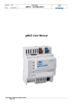
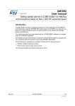
UM1759
User manual
Wireless M-Bus firmware and application
Introduction
The M-Bus (meter bus) is a common standard used for AMR implementation in remote
energy meter readers based on European standards (physical and link layer: EN 13757-2;
application layer: EN 13757-3). The M-Bus is also compliant with European Standard
EN 1434 on heat meters.
The M-Bus interface is very cost effective, because it is designed for communication over
twisted pair cables. For long distance communication, it supports all network configurations
(linear, star, etc.), except for ring networks. When queried, the meters send data to a
concentrator which can be accessed either locally or remotely.
A radio variant of M-Bus, Wireless M-Bus, is also specified in EN 13757-4.
The Wireless Meter Bus is an open standard for Automatic Meter Reading at sub-1 GHz RF.
The relevant standards are:
• European standard prEN 13757-4:2011 Wireless meter readout
• European standard EN 13757-3:2004 Dedicated application layer (in common with MBus)
• ETSI EN 300 220 v2.3.1
The Wireless M-Bus firmware stack is based on EN 13757-4:2011.10 (Communication
systems for meters and remote reading of meters - Part 4: Wireless meter readout (Radio
meter reading for operation in SRD bands)). This European Standard specifies the required
physical and link layer parameters for systems using radio to read remote meters, especially
for short range device (SRD) unlicensed telemetry bands. The standard encompasses
systems for walk-by, drive-by and fixed installations.
Figure 1. Basic Wireless M-Bus architecture
June 2014
DocID026279 Rev 1
1/50
www.st.com
Contents
UM1759
Contents
1
Description . . . . . . . . . . . . . . . . . . . . . . . . . . . . . . . . . . . . . . . . . . . . . . . . . 4
2
Getting started . . . . . . . . . . . . . . . . . . . . . . . . . . . . . . . . . . . . . . . . . . . . . . 6
3
2.1
Package . . . . . . . . . . . . . . . . . . . . . . . . . . . . . . . . . . . . . . . . . . . . . . . . . . . 6
2.2
GUI installation . . . . . . . . . . . . . . . . . . . . . . . . . . . . . . . . . . . . . . . . . . . . . . 6
2.3
Hardware set-up . . . . . . . . . . . . . . . . . . . . . . . . . . . . . . . . . . . . . . . . . . . . . 7
Hardware description . . . . . . . . . . . . . . . . . . . . . . . . . . . . . . . . . . . . . . . 10
3.1
3.2
STEVAL-IKR002Vx (RF motherboard) . . . . . . . . . . . . . . . . . . . . . . . . . . . 10
3.1.1
Microcontroller and connections . . . . . . . . . . . . . . . . . . . . . . . . . . . . . . 11
3.1.2
Power . . . . . . . . . . . . . . . . . . . . . . . . . . . . . . . . . . . . . . . . . . . . . . . . . . . 11
3.1.3
Sensors . . . . . . . . . . . . . . . . . . . . . . . . . . . . . . . . . . . . . . . . . . . . . . . . . 11
3.1.4
Extension connector . . . . . . . . . . . . . . . . . . . . . . . . . . . . . . . . . . . . . . . 11
3.1.5
Daughter board test point . . . . . . . . . . . . . . . . . . . . . . . . . . . . . . . . . . . 12
3.1.6
Push buttons and joystick . . . . . . . . . . . . . . . . . . . . . . . . . . . . . . . . . . . 12
3.1.7
JTAG connector . . . . . . . . . . . . . . . . . . . . . . . . . . . . . . . . . . . . . . . . . . . 12
3.1.8
LEDs . . . . . . . . . . . . . . . . . . . . . . . . . . . . . . . . . . . . . . . . . . . . . . . . . . . 12
STEVAL-IKR002Vx (RF module) . . . . . . . . . . . . . . . . . . . . . . . . . . . . . . . 12
3.2.1
3.3
3.4
3.5
4
STEVAL-IDS001Vx (SPIRIT1 USB dongle) . . . . . . . . . . . . . . . . . . . . . . . 14
3.3.1
Microcontroller and connections . . . . . . . . . . . . . . . . . . . . . . . . . . . . . . 15
3.3.2
Extension connector . . . . . . . . . . . . . . . . . . . . . . . . . . . . . . . . . . . . . . . 15
3.3.3
SWD interface . . . . . . . . . . . . . . . . . . . . . . . . . . . . . . . . . . . . . . . . . . . . 15
3.3.4
Band . . . . . . . . . . . . . . . . . . . . . . . . . . . . . . . . . . . . . . . . . . . . . . . . . . . 17
3.3.5
RF connector . . . . . . . . . . . . . . . . . . . . . . . . . . . . . . . . . . . . . . . . . . . . . 17
3.3.6
Push buttons . . . . . . . . . . . . . . . . . . . . . . . . . . . . . . . . . . . . . . . . . . . . . 17
3.3.7
LEDs . . . . . . . . . . . . . . . . . . . . . . . . . . . . . . . . . . . . . . . . . . . . . . . . . . . 17
STEVAL-IKR001Vx . . . . . . . . . . . . . . . . . . . . . . . . . . . . . . . . . . . . . . . . . 18
3.4.1
STEVAL-IKR001Vx (RF motherboard) . . . . . . . . . . . . . . . . . . . . . . . . . 18
3.4.2
STEVAL-IKR001Vx (RF module) . . . . . . . . . . . . . . . . . . . . . . . . . . . . . . 19
Hardware connection between MCU and SPIRIT1 module . . . . . . . . . . . 20
Wireless M-Bus firmware APIs . . . . . . . . . . . . . . . . . . . . . . . . . . . . . . . . 23
4.1
2/50
Boost mode . . . . . . . . . . . . . . . . . . . . . . . . . . . . . . . . . . . . . . . . . . . . . . 13
Wireless M-Bus APIs . . . . . . . . . . . . . . . . . . . . . . . . . . . . . . . . . . . . . . . . 23
DocID026279 Rev 1
UM1759
5
Contents
File description . . . . . . . . . . . . . . . . . . . . . . . . . . . . . . . . . . . . . . . . . . . . 23
4.1.2
WMBus_Appli.c: functions description . . . . . . . . . . . . . . . . . . . . . . . . . . 24
4.1.3
AES128.c: functions description . . . . . . . . . . . . . . . . . . . . . . . . . . . . . . 31
4.1.4
AES128_ctr.c: functions description . . . . . . . . . . . . . . . . . . . . . . . . . . . 32
4.1.5
WMBus_PhyDataMem.c: functions description . . . . . . . . . . . . . . . . . . . 34
Running the Wireless M-Bus application . . . . . . . . . . . . . . . . . . . . . . . 36
5.1
WMBUS application workspace . . . . . . . . . . . . . . . . . . . . . . . . . . . . . . . . 36
5.2
Default configuration . . . . . . . . . . . . . . . . . . . . . . . . . . . . . . . . . . . . . . . . 36
5.3
Running evaluation board . . . . . . . . . . . . . . . . . . . . . . . . . . . . . . . . . . . . 38
5.4
5.5
6
4.1.1
5.3.1
Programming the evaluation board with firmware . . . . . . . . . . . . . . . . . 38
5.3.2
Installation sequence . . . . . . . . . . . . . . . . . . . . . . . . . . . . . . . . . . . . . . . 41
5.3.3
Data communication sequence: (meter must be installed to the
concentrator prior to this step) 41
Using evaluation board with GUI . . . . . . . . . . . . . . . . . . . . . . . . . . . . . . . 41
5.4.1
GUI description . . . . . . . . . . . . . . . . . . . . . . . . . . . . . . . . . . . . . . . . . . . 42
5.4.2
Configuration window . . . . . . . . . . . . . . . . . . . . . . . . . . . . . . . . . . . . . . 42
5.4.3
Meter window . . . . . . . . . . . . . . . . . . . . . . . . . . . . . . . . . . . . . . . . . . . . . 42
5.4.4
Monitoring window . . . . . . . . . . . . . . . . . . . . . . . . . . . . . . . . . . . . . . . . . 43
Board configuration with PC-GUI . . . . . . . . . . . . . . . . . . . . . . . . . . . . . . . 44
Revision history . . . . . . . . . . . . . . . . . . . . . . . . . . . . . . . . . . . . . . . . . . . 49
DocID026279 Rev 1
3/50
50
Description
1
UM1759
Description
The Wireless M-Bus standard is defined by European Standard EN 13757-4 for physical
and data link layers, while the application layer is defined by EN 13757-3.
The different types of devices are:
1.
Meters
2.
Concentrators/Read-out devices
3.
Routers
The standard defines the communication between remote meters and mobile readout
devices, stationary receivers, data collectors, etc. A typical application scenario is shown
below:
Figure 2. Final application scenario
STMicroelectronics has developed a Wireless M-Bus firmware stack implementation based
on its proprietary dual chip platform: the new SPIRIT1 RF Sub-1 GHz transceiver and the
STM32L15 ultra-low-power ARM Cortex-M3 microcontroller.
SPIRIT1:
The SPIRIT1 device is a very low-power, high performance RF transceiver intended for RF
wireless applications in the sub-1 GHz band. It is designed to operate at 169, 315, 433, 868,
and 915 MHz frequencies, and supports the following modulations: 2-FSK, GFSK, MSK,
OOK, and ASK. The air data rate is programmable from 1 to 500 kbps, depending on the
selected modulation.
It has an integrated SMPS for very low power consumption: 9 mA in Rx and 21 mA in Tx
mode at +11 dBm.
It uses a very small number of discrete external components and integrates a configurable
baseband modem which supports data management, modulation and demodulation. Data
management supports our proprietary, fully-programmable packet format, as well as the MBus standard compliance format (all performance classes).
The SPIRIT1 is the native HW supporting the low level of the WM-Bus PHY protocol.
4/50
DocID026279 Rev 1
UM1759
Description
ST Ultra Low Power MCU: EnergyLite™ Family
The EnergyLite™ family of 8-bit (STM8L) and 32-bit (STM32L) MCUs are designed to meet
the high-performance and energy-efficiency requirements of typically battery-powered gas,
water, and heat meters in the WM-Bus scenario.
The STM8L and STM32L devices offer specific features for ultra-low power applications,
including advanced ultra-low power modes, optimized dynamic run consumption and
special safety features.
The ultra-low-power EnergyLite™ platform is based on the STMicroelectronics 130 nm
ultra-low-leakage process technology, sharing common technology, architecture and
peripherals.
The STM32 L1 series, based on ARM® Cortex™-M3, extends the ultra-low power concept
without compromising performance. More than just ultra-low-power MCUs, the STM32 L1
series offers a wide portfolio of features, memory sizes and package pin counts: from 32 to
384 Kbytes of Flash memory (with up to 48 Kbytes of RAM and 12 Kbytes of true embedded
EEPROM), and from 48 to 144 pins.
The innovative architecture (with voltage scaling and ultra-low-power MSI oscillator) adds
performance to design solutions requiring a very low power budget. The large number of
embedded peripherals (USB, LCD interface, op amp, comparator, ADC with fast on/off
mode, DAC, capacitive touch and AES), means that the STM32 L1 series is an expandable
platform able to satisfy all application requirements.
The STMicroelectronics WM-Bus application
layer is explained in this user manual.
DocID026279 Rev 1
5/50
50
Getting started
UM1759
2
Getting started
2.1
Package
The Wireless M-Bus package Includes the following:
1.
2.
3.
Documentation:
–
Wireless M-Bus firmware and application user manual (this document)
–
Wireless M-Bus stack application note
–
The GUI help file
Firmware:
–
Wireless M-Bus firmware
–
SPIRIT1_Libraries
–
STM32L1xx_StdPeriph_Lib
–
STM32_USB-FS-Device_Driver
–
WMBUS application and library files
PC-GUI:
–
2.2
The PC-GUI setup
GUI installation
Download the set-up file for latest version of the GUI from the following link:
http://ims.st.com/systemslab/download/setups/read_only.php?group_projects=0&pow_cod
e=SW.APP0123.13.
To install the GUI, the user should log on as administrator. SQL server compact is required
by the GUI and is included in the installation program; if it is not already installed, the user is
prompted to install it during the GUI installation routine.
Figure 3. Snapshot of GUI installation
The user then proceeds to accept the license agreement and complete the installation.
6/50
DocID026279 Rev 1
UM1759
2.3
Getting started
Hardware set-up
The default firmware runs on the demo boards shown below.
Figure 4. STEVAL- IKR002Vx board
•
A: mini USB connector CN1
•
B: jumper JP1 (position 1-2 = USB power source, position 2-3 = battery power source)
•
C: green LED DL6 (board is powered ON)
•
D: LIS3DH, an ultra-low power high performance three axes linear accelerometer
•
E: STLM75, a high precision digital CMOS temperature sensor, with I2C interface
•
F: extension connector
•
G: user interaction buttons (RESET, PUSH_BUTTON and JOYSTICK)
•
H: JTAG connector
•
I: five LEDs (DL1: green, DL2: orange, DL3: red, DL4: blue, DL5: yellow)
•
M: daughter board test points
•
L: RF module interface connector
DocID026279 Rev 1
7/50
50
Getting started
UM1759
STEVAL-IDS001Vx board:
Figure 5. STEVAL-IDS001Vx board top
Figure 6. STEVAL-IDS001Vx board bottom
8/50
DocID026279 Rev 1
UM1759
Getting started
STEVAL- IKR001Vx board:
Figure 7. STEVAL- IKR001Vx motherboard and RF module
DocID026279 Rev 1
9/50
50
Hardware description
3
UM1759
Hardware description
The hardware supported includes:
• STEVAL-IKR002Vx
• STEVAL-IKR001Vx
• STEVAL-IDS001Vx
where x = 2, 3, 4, and 5.
3.1
STEVAL-IKR002Vx (RF motherboard)
The STM32L microcontroller on the RF motherboard drives the SPIRIT1 transceiver and
communicates with PCs via USB.
A connector on the motherboard (Figure 8) allows JTAG interface access for programming
and debugging. The board can be powered through a mini-USB connector that may also be
used for I/O interaction with a USB Host. The board also has a user button, a joystick and
RESET button for user interaction. A temperature sensor and accelerometer are included
on the board. The RF module can be connected easily via a dedicated interface.
The features available on the boards include:
10/50
•
STM32L151RBT6 64-pin microcontroller
•
Mini USB connector for power supply and I/O
•
JTAG connector
•
RF daughterboard interface
•
One RESET button and one USER button
•
One LIS3DH accelerometer
•
One STLM75 temperature sensor
•
One joystick
•
5 LEDs
•
One PWR LED
•
One battery holder for 2 AAA batteries
•
One row of test points on the interface with the RF daughterboard
DocID026279 Rev 1
UM1759
Hardware description
Figure 8. STEVAL-IKR002Vx (RF motherboard)
3.1.1
Microcontroller and connections
The board has an STM32L151RB microcontroller. It’s an ultra-low-power microcontroller
with 128 KB of flash memory, 16 KB of RAM, 32-bit core ARM cortex-M3, 4 KB of data
EEPROM, RTC, LCD, timers, USART, I2C, SPI, ADC, DAC and comparators.
The microcontroller is connected to different components including buttons, LEDs and
connectors for external circuitry.
3.1.2
Power
The board can be powered either by the mini USB connector CN1 (area A in Figure 8) or by
two AAA batteries. To power the board via the USB bus, place jumper JP1 in position 1-2
(area B in Figure 8). To power the board with batteries, place two AAA batteries in the
battery holder at the rear of the board and set jumper JP1 to position 2-3.
When the board is powered, the green LED DL6 is ON (area C in Figure 8).
The board can also be powered by an external DC power supply. Connect the positive
output of the power supply to the central pin of JP1 (pin 2) and the ground to one of the four
test point connectors on the motherboard.
3.1.3
Sensors
Two sensors are available on the motherboard:
3.1.4
•
LIS3DH; an ultra-low power, high performance three-axes linear accelerometer (area D
in Figure 8). The sensor is connected to the STM32L through the SPI interface. Two
lines for interrupts are also connected.
•
STLM75; a high-precision digital CMOS temperature sensor, with I2C interface (area E
in Figure 8). The pin for the alarm function is connected to one of the STM32L GPIOs.
Extension connector
You can solder a connector on the motherboard to extend its functionality (area F in
Figure 8). 16 pins of the microcontroller are connected to this expansion slot.
DocID026279 Rev 1
11/50
50
Hardware description
3.1.5
UM1759
Daughter board test point
A row of test points (area M in Figure 8) is available for debugging and testing. The available
signals are:
1.
GND
2.
VDD
3.
GPIO SDN (the pin to drive the SHUTDOWN for SPIRIT1)
4.
SPI CSn
5.
SPI MISO
6.
SPI MOSI
7.
SPI SCKL
8.
SPIRIT1 GPIO2
9.
SPIRIT1 GPIO3
10. SPIRIT1 GPIO1
11. SPIRIT1 GPIO0
12. GND
3.1.6
Push buttons and joystick
The board has two buttons, one to reset the microcontroller and the other is available to the
application, and a digital joystick with 4 possible positions (left, right, up, down) (area G in
Figure 8).
3.1.7
JTAG connector
A JTAG connector (area H in Figure 8) allows on-board programming and debugging of the
STM32L microcontroller using an in-circuit debugger and programmer like the ST-LINK/V2.
3.1.8
LEDs
Five LEDs are available (area I in Figure 8).
3.2
•
DL1: green
•
DL2: orange
•
DL3: red
•
DL4: blue
•
DL5: yellow
STEVAL-IKR002Vx (RF module)
The RF module includes 5 different possible BOM lists on the same PCB layout. Each one
is optimized for the following different RF bands:
12/50
•
169 MHz
•
315 MHz
•
433 MHz
•
868 MHz
•
915 MHz
DocID026279 Rev 1
UM1759
Hardware description
The band is indicated by a dummy resistor on the board (area A in Figure 9). An SMA
connector on the RF module (area B in Figure 9) allows connection with RF instruments like
spectrum analyzers and signal generators to the SPIRIT1 by RF cable, or connection with
an antenna like the one included in the demo kit. The board is powered by the RF
motherboard through the RF daughterboard connector (area D in Figure 9) and
communicates with the microcontroller through this connector via SPI and some GPIOs.
The Vcc_RF pin of the RF daughterboard connector is linked to the Vbat of the SPIRIT1
through a jumper that can also be removed to measure current consumption (area C in
Figure 9).
The RF module includes a memory EEPROM with RF module data stored at the time of
manufacture. The information is stored in the first pages of the EEPROM and the memory
may not be changed by user.
Figure 9. STEVAL-IKR002Vx (RF module)
3.2.1
Boost mode
The SPIRIT1 can be configured to increase the output power in transmission mode.
In the default configuration, the transmitter power amplifier (PA) output is biased by the
1.4 V SMPS voltage output through the L0 external inductor (position D0 in the schematic,
Figure 10). This limits the maximum output power to about +11 dBm, measured at the
50 Ohm connector via the reference design.
Biasing the PA output through the inductor L0 directly connected to the battery instead of
the SMPS output increases the maximum output power delivered at the 50 Ohm connector
(or at the antenna). The maximum output power changes with the voltage level applied at
the PA output.
To switch to boost mode, the inductor L0 must be removed from position 1-2 D0 in the
schematic and soldered at position 1-3 D0, then the voltage supply Vcc_RF must be
provided.
DocID026279 Rev 1
13/50
50
Hardware description
UM1759
Figure 10. STEVAL-IKR002Vx (RF module) boost mode configuration
For more information see the application note AN4198 - SPIRIT1: increasing the output
power, available on the SPIRIT1 web site or in the document folder of this release.
3.3
STEVAL-IDS001Vx (SPIRIT1 USB dongle)
The STEVAL-IDS001Vx is a single board that includes the SPIRIT1 radio transceiver and
STM32L microcontroller.
A strip line can be soldered, in B Figure 11, allowing the access to the SWD interface for
programming and debugging and to the 4 GPIOs of the SPIRIT1. The board can be
powered through the USB connector, in A Figure 11, that can also be used for I/O
interaction with a USB Host. The board has also two user buttons for user interaction, in G
Figure 11.
This is the list of some of the features that are available on the module:
•
14/50
SPIRIT1 radio transceiver, in D Figure 11.
•
STM32L151CBU6 48-pin microcontroller, in C Figure 11.
•
USB connector for power supply and I/O, in A Figure 11.
•
One row of pins with SWD interface and SPIRIT1's GPIOs, in B Figure 11.
•
Chip antenna tuned for the entire bands supported (315 MHz, 433 MHz, 868 MHz and
915 MHz), in F Figure 11.
•
Two user buttons, in G Figure 11.
•
LEDs, in H Figure 11.
DocID026279 Rev 1
UM1759
Hardware description
Figure 11. STEVAL-IDS001Vx
3.3.1
Microcontroller and connections
The board has an STM32L151CBU6 microcontroller. It's an ultralow power microcontroller
with 128 KB of flash memory, 16 KB of RAM, 32-bit core ARM cortex-M3, 4 KB of data
EEPROM, RTC, timers, USART, I2C, SPI, ADC, DAC and comparators.
The microcontroller is connected to different components like buttons, LEDs and connectors
for external circuitry.
3.3.2
Extension connector
There is the possibility to solder a strip line connector on the motherboard to access to the
SWD interface for programming and debugging, and to access to the 4 GPIOs of the
SPIRIT1, in B Figure 11.
3.3.3
SWD interface
The SWD interface is available through the pins in B in Figure 12. The SWD interface allows
programming and de-bugging of the STM32L microcontroller on board, using an in-circuit
debugger and programmer like the ST-LINK/V2. In Figure 12 the connection scheme to how
connect the ST-LINK/V2 with the board pins is showed.
DocID026279 Rev 1
15/50
50
Hardware description
UM1759
Figure 12. SWD connection scheme with ST-LINK/V2
The signals available on the STEVAL-IDS001Vx are:
1.
GND
2.
VDD
3.
nRESET
4.
SWDIO
5.
SWO/TRACE
6.
SWCLK
7.
SPIRIT1 GPIO0
8.
SPIRIT1 GPIO1
9.
SPIRIT1 GPIO2
10. SPIRIT1 GPIO3
The connection with the ST-LINK/V2 interface is the following, as showed in Figure 12.
Table 1. SWD connection
16/50
Signal name
STEVAL-IDS001Vx pin
number
ST-LINK/V2 pin number
GND
1
14
VDD
2
2
nRESET
3
15
SWDIO
4
7
SWO/TRACE
5
13
SWCLK
6
9
DocID026279 Rev 1
UM1759
3.3.4
Hardware description
Band
The STEVAL-IDS001Vx has 4 different possible BOM lists, each one optimized for different
RF band as follow:
•
315 MHz
•
433 MHz
•
868 MHz
•
915 MHz
The chip antenna used supports all these four bands of frequency.
3.3.5
RF connector
The STEVAL-IDS001Vx provides two different RF connections: antenna (chip antenna
tuned for all the supported bands, default configuration) and UFL connector. Although the
default configuration allows communication on air, can be useful switch to the UFL
connector to connect the STEVAL-IDS001Vx to RF equipment as spectrum analyzer or RF
signal generator. To switch from antenna to UFL connector the C9 capacitor must be
removed and the C36 capacitor must be soldered. To restore the default configuration and
use the antenna the C36 capacitor must be removed and the C9 capacitor must be
soldered. In Figure 13, the two pads for C9 and C36 are showed together with the chip
antenna and UFL connector. According to the particular BOM, for each band, the value of
C36 is equals to C9.
Figure 13. RF connector scheme
3.3.6
Push buttons
For user interaction the board has two buttons both available to the application, G in F
Figure 11.
3.3.7
LEDs
Two LEDs are available (H in Figure 11).
•
D1: yellow.
•
D2: green.
DocID026279 Rev 1
17/50
50
Hardware description
3.4
UM1759
STEVAL-IKR001Vx
The SPIRIT1 DK is made up of two units connected to one PC or two PCs with USB cables.
Each unit is composed of an antenna for the selected band and two PCBs:
3.4.1
•
RF motherboard
•
RF module
STEVAL-IKR001Vx (RF motherboard)
The previous version of the motherboard is supported. The supply voltage is provided or by
USB cable or by external power supply. The switch S1 turns on or off the SPIRIT1 DK - MB.
Figure 14 highlights some features of the board as follow:
1.
The power supply sources: USB connector and jack connector for external power
supply. USB connector is used also for I/O with the microcontroller with a virtual COM
port exposed to the PC.
2.
Switch to turn ON or OFF the board.
3.
JTAG/SWD connector.
4.
Three button and a joystick:
5.
a)
SCM_PS, not used
b)
RESET, for resetting the MB board
c)
Push_Button, used to enter in DFU mode
d)
Joystick, not used
Test point (TP), to probe the SPI signals, the 4 GPIOs of the SPIRIT1, the shutdown of
the SPIRIT1 (SDN), the supply voltage of the SPIRIT1 (VCCRF). The list of signals
available is:
a)
GND
b)
VCC_RF
c)
GPIO SDN (the pin to drive in SHUTDOWN the SPIRIT1)
d)
SPI CSn
e)
SPI MISO
f)
SPI MOSI
g)
SPI SCKL
h)
SPIRIT1 GPIO2
i)
SPIRIT1 GPIO3
j)
SPIRIT1 GPIO1
k)
SPIRIT1 GPIO0
l)
GND
m) Five LEDs
n)
18/50
SMA connector
DocID026279 Rev 1
UM1759
Hardware description
Figure 14. STEVAL-IKR001Vx (RF motherboard)
3.4.2
STEVAL-IKR001Vx (RF module)
The RF module includes 5 different possible BOM lists, on the same layout PCB. Each one
optimized for different RF band as follow:
•
169 MHz
•
315 MHz
•
433 MHz
•
868 MHz
•
915 MHz
The band indication is reported with a dummy resistor on the board, in A Figure 15. A SMA
connector on the RF module, in B Figure 15, allows connection with RF instruments as
spectrum analyzer and signal generator to the SPIRIT1 by RF cable or also connect an
antenna as the one included in the demo kit. The board is powered through the RF
daughterboard connector, in D Figure 15, by the RF motherboard and communicates
through this connector by SPI and some GPIOs with the microcontroller.
The Vcc_RF pin of the RF daughterboard connector is linked to the Vbat of the SPIRIT1
through a jumper that can be also removed to measure the current consumption, in C
Figure 15.
DocID026279 Rev 1
19/50
50
Hardware description
UM1759
Figure 15. STEVAL-IKR001Vx (RF module)
3.5
Hardware connection between MCU and SPIRIT1 module
The hardware connection between MCU (STM32L) and SPIRIT1 is using the following pins.
This is the minimum connection needed for communication between STM32L and SPIRIT1
device.
Figure 16. Connection diagram
The evaluation board is connected with SPIRIT1 module as per the table given below. The
connections are shown for both connectors J6 and J7 in the STEVAL-IKR001Vx board.
Table 2. Evaluation board connection with connector J6
20/50
Evaluation board
SPIRIT1 module (J6)
NC
Pin#1 (NC)
3V3
Pin#2 (3V3)
NC
Pin#3 (NC)
NC
Pin#4 (NC)
GND
Pin#5 (GND)
NC
Pin#6 (NC)
GND
Pin#7 (GND)
DocID026279 Rev 1
UM1759
Hardware description
Table 2. Evaluation board connection with connector J6
Evaluation board
SPIRIT1 module (J6)
3V3
Pin#8 (VccRF)
PC.2
Pin#9 (SDN)
3V3
Pin#10 (VccRF)
Table 3. Evaluation board connection with connector J7
Evaluation board
SPIRIT1 module (J7)
GND
Pin#1 (GND)
GND
Pin#2 (GND)
Px.x (SPI_CS)
Pin#3(CS/NSS)
Px.x
Pin#4 (GPIO_3)
Px.x (SPI_SCK)
Pin#5 (CLK)
Px.x
Pin#6 (GPIO_2)
Px.x (SPI_MOSI)
Pin#7 (SDI)
Px.x
Pin#8 (GPIO_1)
Px.x (SPI_MISO)
Pin#9 (SDO)
Px.x
Pin#10 (GPIO_0)
The WM-Bus protocol stack is developed on ST’s dual chip platform The SPIRIT1 is just
implementing part of the WM-Bus physical layer, the PHY and LINK firmware stack layers
are implemented STM32L15x, Ultra low power ARM Cortex-M3.
STM32L role
•
WM-Bus Application Layer
–
•
•
Wireless M-Bus application layer partially implements the EN13757-3.
WM-Bus Link Layer
–
MAC packet and CRC handling
–
Encryption/ Decryption initiate/read.
WM-Bus PHY
–
Init PHY for WM-Bus
–
Interrupt Services
SPIRIT1 role
•
WM-Bus Modes
•
Header, Sync and trailer fields
•
Manchester/3-out-of-6-encoding
•
Sync detection
•
Tx and RX FIFO
DocID026279 Rev 1
21/50
50
Hardware description
UM1759
Figure 17. Software architecture
22/50
DocID026279 Rev 1
UM1759
Wireless M-Bus firmware APIs
4
Wireless M-Bus firmware APIs
4.1
Wireless M-Bus APIs
4.1.1
File description
The following are the files used for WM-Bus application layer implementation.
Figure 18. Structure of WMBUS application header file
Figure 19. Structure of WMBUS application source file
DocID026279 Rev 1
23/50
50
Wireless M-Bus firmware APIs
UM1759
Table 4. WM-Bus Application layer files
Filename
Description
wmbus_appli.c
This file includes routines for WMBus application Layer
wmbus_appli.h
This file contains header for wmbus_appli.c
aes128.h
This file includes header for aes128
aes128.c
This file contains AES 128-bit key main program body
aes128_ctr.c
This file contains the aes-ctr and aes-cbc program body
Wmbus_phydatamem.c This function contains routine for DATA EEPROM read and write of MCU
Wmbus_phydatamem.h This function contains the header for Wmbus_phydatamem.c
4.1.2
WMBus_Appli.c: functions description
The list of application layer routines is given below as described in wmbus_appli.c.
Table 5. WM-Bus application add meter routine
Name
WMBus_AppliAddMeter
Parameters
WMBusDatabaseFrame_t databaseFrame:The meter parameters
Description
This function will add meter to the database
Return type
SpiritBool: (S_TRUE or S_FALSE)
Table 6. WM-Bus application delete meter routine
Name
WMBus_AppliDeleteMeter
Parameters
uint64_t meterid: The meter ID
Description
This function will delete the meter from the database
Return type
SpiritBool: (S_TRUE or S_FALSE)
Table 7. WM-Bus application get encryption key routine
Name
WMBus_AppliGetEncryptKey
Parameters
EncryptionKey_t *keydata: The pointer to Encryption key string
Description
This function will return the encryption key
Return type
None
Table 8. WM-Bus application get frame format routine
24/50
Name
WMBus_AppliGetFrameFormat
Parameters
None
DocID026279 Rev 1
UM1759
Wireless M-Bus firmware APIs
Table 8. WM-Bus application get frame format routine
Description
This function will return the WMBus frame format
Return type
FrameFormatType_t
Table 9. WM-Bus application get group attribute routine
Name
WMBus_AppliGetGroupAttr
Parameters
uint8_t groupid: The group ID
Description
This function will return the number of meters in the group
Return type
uint16_t: The number of meters in the group
Table 10. WM-Bus application get group members routine
Name
WMBus_AppliGetGroupMembers
Parameters
MeterDatabase_t *pdatabase:The pointer to the array of MeterDatabase_t
type
uint8_t groupid:group ID
Description
This function will fill update the meter ID and Group ID in the parameter
passed and also return the number of meters in the database
Return type
uint16_t: The number of the meters in the database
Table 11. WM-Bus application get meter list routine
Name
WMBus_AppliGetMeterList
Parameters
MeterDatabase_t *pdatabase:The pointer to the array of MeterDatabase_t
type
Description
This function will fill update the meter ID and Group ID in the parameter
passed and also return the number of meters in the database
Return type
uint16_t: The number of the meters in the database.
Table 12. WM-Bus application get operation mode routine
Name
WMBus_AppliGetOperationMode
Parameters
None
Description
This function will RETURN the current operation mode
Return type
WMBusOperationMode_t
DocID026279 Rev 1
25/50
50
Wireless M-Bus firmware APIs
UM1759
Table 13. WM-Bus application indication call back routine
Name
WMBus_AppliIndicaCallback
Parameters
Indication *indic: This indicates type of request and associated data
LastEventLog_t LastEvent: log of last event
Description
This function is called after invoking the indication service
Return type
None
Table 14. WM-Bus application initialization routine
Name
WMBus_AppliInit
Parameters
None
Description
This function will init the WMBUS application
Return type
None
Table 15. WM-Bus application poll requests routine
Name
WMBus_AppliPollRequests
Parameters
None
Description
This function will poll for the requests coming from the meters
Return type
LINK_STATUS
Table 16. WM-Bus application power on routine
Name
WMBus_AppliPowerOn
Parameters
None
Description
This function will init the link layer after power on
Return type
LINK_STATUS
Table 17. WM-Bus application read meter routine
26/50
Name
WMBus_AppliReadMeter
Parameters
uint64_t meterID
uint8_t *buff :pointer to buffer
Description
This function will handle meter read request from the PC-GUI
Return type
length of the payload
DocID026279 Rev 1
UM1759
Wireless M-Bus firmware APIs
Table 18. WM-Bus application read meter attribute routine
Name
WMBus_AppliReadMeterAttr
Parameters
uint64_t MeterIDTemp The meter ID database
uint8_t *tempBuff: The uint8_t array that contains the Board MFR ID
Description
This function will return the board Manufacturer
ID(MFR+IDENTIFICATION) and encryption key
Return type
LINK_STATUS
Table 19. WM-Bus application received data handler routine
Name
WMBus_AppliRxDataHandler
Parameters
Frame frame: The pointer to the link frame.
Description
This function will handle the received data from the link layer.
Return type
None
Table 20. WM-Bus application send meter data routine
Name
WMBus_AppliSendMeterData
Parameters
uint8_t *buff, uint8_t length
Description
This function will send Meter Data to concentrator.
Return type
LINK_STATUS
Table 21. WM-Bus application send meter installation request routine
Name
WMBus_appliSendMeterInstallationRequest
Parameters
None
Description
This function will handle the install meter request
Return type
LINK_STATUS
Table 22. WM-Bus application set encryption key routine
Name
WMBus_AppliSetEncryptKey
Parameters
EncryptionKey_t keydata: The Encryption key.
void *mfrID: The pointer to MFR IF+A-Field String.
Description
This function will set the Encryption key.
Return type
None
DocID026279 Rev 1
27/50
50
Wireless M-Bus firmware APIs
UM1759
Table 23. WM-Bus application set frame format routine
Name
WMBus_AppliSetFrameFormat
Parameters
FrameFormatType_t frameFormat
Description
This function will set the frame format
Return type
LINK_STATUS
Table 24. WM-Bus application set operation mode routine
Name
WMBus_AppliSetOperationMode
Parameters
WMBusOperationMode_t currmode: The current operation mode.
Description
This function will set the current operation mode.
Return type
None
Table 25. WM-Bus application data transmission sent routine
Name
WMBus_AppliTxDataSentHandler
Parameters
LINK_STATUS status
LastEventLog_t LastEvent
Description
This function handles the data transmission and returns the link status and
last event occurred
Return type
None
Table 26. WM-Bus application update meter attribute routine
Name
WMBus_AppliUpdateMeterAttr
Parameters
WMBusDatabaseFrame_t databaseFrame: The database frame contains
meter attribute.
Description
This function will update the meter attributes (This will not add meter).
Return type
SpiritBool
Table 27. WM-Bus application update meter database routine
28/50
Name
WMBus_AppliUpdateMeterDatabase
Parameters
Frame *frame: The database frame contains meter data.
DocID026279 Rev 1
UM1759
Wireless M-Bus firmware APIs
Table 27. WM-Bus application update meter database routine
Description
This function will update the data received from the meters over WMBus
interface.This will ignore if the meter is not registered.
Return type
SpiritBool
Table 28. WM-Bus application write meter database routine
Name
WMBUS_AppliWriteMeterDatabase
Parameters
None
Description
This function writes Meter database to internal EEPROM.
Return type
None
Table 29. WM-Bus application get board manufacturing ID routine
Name
WMBus_GetBoardMnfID
Parameters
uint8_t *buff: The uint8_t array that contains the Board MFR ID.
Description
This function will return the board Manufacturer
ID(MFR+IDENTIFICATION).
Return type
None
Table 30. WM-Bus application get time routine
Name
WMBus_GetTime
Parameters
uint32_t *date, uint32_t *time
Description
This function will the return Date and time
Return type
SpiritBool
Table 31. WM-Bus application get device type routine
Name
WMBus_GetWMBusDeviceType
Parameters
None
Description
This function will return the WMBus device type.
Return type
WMBusDeviceType_T:
0x01 -> METER
0x02 -> OTHER
0x03 -> ROUTER
0x04 -> SNIFFER
0xFF -> NOT_CONFIGURED
DocID026279 Rev 1
29/50
50
Wireless M-Bus firmware APIs
UM1759
Table 32. WM-Bus application set board manufacturing ID routine
Name
WMBus_SetBoardMnfID
Parameters
uint8_t *buff: The MFR ID in array format.
Description
This function will set the MFR ID(MFR+Identification field).
Return type
SpiritBool
Table 33. WM-Bus application set time routine
Name
WMBus_SetTime
Parameters
uint32_t date, uint32_t time
Description
This function will the set time and date of the board
Return type
SpiritBool
Table 34. WM-Bus application RTC configuration routine
Name
RTC_Config
Parameters
None
Description
This function will Configure the RTC clock source
Return type
None
Table 35. WM-Bus application radio power on routine
Name
Appli_RadioPowerON
Parameters
None
Description
This function will turn on the radio and waits till it enters the ready state
Return type
None
Table 36. WM-Bus application radio power off routine
Name
Appli_RadioPowerOFF
Parameters
None
Description
This function will shut down the radio
Return type
None
Table 37. WM-Bus application radio stand-by routine
30/50
Name
Appli_RadioStandBy
Parameters
None
DocID026279 Rev 1
UM1759
Wireless M-Bus firmware APIs
Table 37. WM-Bus application radio stand-by routine
Description
This function will put the radio in standby state
Return type
None
Table 38. WM-Bus application get EEPROM entries routine
Name
WMBus_AppliGetEEpromEntries
Parameters
None
Description
This function will read and send all meter entry in EEPROM of concentrator
database to GUI
Return type
uint8_t*: ptr to the buffer returned
Table 39. WM-Bus application write meter database in EEPROM routine
4.1.3
Name
Write_Meter_DB_EEPROM
Parameters
None
Description
This function will write meter database to EEPROM
Return type
uint8_t*: ptr to the buffer returned
AES128.c: functions description
The list of encryption layer (which is also part of application layer) routines is given below as
described in aes128_ctr.c.
Table 40. WM-Bus AES decryption routine
Name
AES_decrypt
Parameters
u32* input_pointer, u32* output_pointer
u32* expkey: decryption key
Description
This routine Decrypts one block of 16 bytes
Return type
None
Table 41. WM-Bus AES encryption routine
Name
AES_encrypt
Parameters
u32* input_pointer, u32* output_pointer
u32* expkey: encryption key
Description
This routine Encrypts one block of 16 bytes
Return type
None
DocID026279 Rev 1
31/50
50
Wireless M-Bus firmware APIs
UM1759
Table 42. WM-Bus AES key schedule for decryption routine
4.1.4
Name
AES_keyschedule_dec
Parameters
u32* key: user key
u32* exp: expanded key
Description
This routine computes the expanded key (expkey) according to key for
AES128 decryption
Return type
None
AES128_ctr.c: functions description
The list of encryption layer (which is also part of application layer) routines is given below as
described in aes128_ctr.c.
Table 43. WM-Bus add counter routine
Name
add_counter
Parameters
u32 *ctr : counter address
Description
This routine increment counter by one upon encryption of each block
Return type
None
Table 44. WM-Bus bit-wise XOR routine
Name
bitwise_xor
Parameters
unsigned char *ina: input block a address
unsigned char *inb: input block b address
unsigned char *out : output block address
Description
This routine is for implementing XOR operation of blocks
Return type
None
Table 45. WM-Bus decrypts PDU routine
32/50
Name
decrypt_pdu
Parameters
u32 *exp_key : expended key address
unsigned char *cipher: input cipher data address
int len: length
unsigned char *plain: output plain data address
Description
This routine decrypts the incoming stream
Return type
None
DocID026279 Rev 1
UM1759
Wireless M-Bus firmware APIs
Table 46. WM-Bus encrypts PDU routine
Name
encrypt_pdu
Parameters
u32 *exp_key : expended key address
unsigned char * plain: input plain data address
int len: length
unsigned char * cipher: output cipher data address
Description
This routine Encrypts the incoming stream
Return type
None
Table 47. WM-Bus encrypts PDU CBC routine
Name
encrypt_pdu_cbc
Parameters
u32 *exp_key : expended key address
unsigned char * plain: input plain data address
int len: length
unsigned char * cipher: output cipher data address
Description
Encrypts the incoming stream using AES-CBC algorithm
Return type
None
Table 48. WM-Bus decrypts PDU CBC routine
Name
decrypt_pdu_cbc
Parameters
u32 *exp_key : expended key address
unsigned char * cipher: output cipher data address
int len: length
unsigned char * plain: input plain data address
Description
Decrypts the incoming stream
Return type
None
Table 49. WM-Bus application encryption routine
Name
WMBus_AppliEncrypt
Parameters
u32 *exp_key : expended key address
unsigned char * plain: input plain data address
int len: length
unsigned char * cipher: output cipher data address
Description
This routine does key expansion before encryption starts
Return type
None
DocID026279 Rev 1
33/50
50
Wireless M-Bus firmware APIs
UM1759
Table 50. WM-Bus application decryption routine
4.1.5
Name
WMBus_AppliDecrypt
Parameters
u32 *key: encryption key
unsigned char *payload: input payload address
int length: length
Description
This routine provides key expansion before decryption starts
Return type
None
WMBus_PhyDataMem.c: functions description
The list of EEPROM function (which is also part of application layer) routines is given below
as described in wmbus_phydatamem.c.
Table 51. WM-Bus read encryption key in EEPROM meter database routine
Name
Read_EEPROM_Mtr_DataBase
Parameters
uint64_t* buff: ptr to the receive meter id i.e. Rev_METER_ID
Description
This function will read the memory region to obtain correct encryption
key corresponding to the meter id received
Return type
None
Table 52. WM-Bus erase EEPROM meter database routine
Name
WMBus_EraseMeterDatabaseFromEEPROM
Parameters
uint8_t *buff: pointer to the buffer that contains entry no. and meter id
uint32_t Saddress: starting address of loction in EEPROM
uint8_t Wordlength: The data length to be deleted.
Description
This function will erase the memory region
Return type
None
Table 53. WM-Bus read meter database routine
34/50
Name
WMBus_PhyReadMeterDatabase
Parameters
uint32_t Saddress: Starting address in EEPROM.
uint16_t length: The length of the data to be read.
uint32_t Eaddress: end address in EEPROM
Description
This function will read the data from the EEPROM
Return type
uint8_t*: pointer to EEpromMtrData
DocID026279 Rev 1
UM1759
Wireless M-Bus firmware APIs
Table 54. WM-Bus write EEPROM meter database routine
Name
WMBus_PhyWriteMeterDatabase
Parameters
uint8_t *buff: The pointer to the data to be written.
uint16_t length: The length of the data to be written.
uint32_t Saddress: Starting address in EEPROM
Description
This function writes data to internal EEPROM
Return type
None
Table 55. WM-Bus read EEPROM database routine
Name
WMBus_ReadMeterEnkeyFromEEPROM
Parameters
uint32_t Saddress: Starting address in EEPROM.
uint16_t length: The length of the data to be read.
uint32_t Eaddress: end address in EEPROM
Description
This function will read the data from the EEPROM
Return type
uint8_t*: pointer to EEpromMtrData
Table 56. WM-Bus write EEPROM database routine
Name
WMBus_WriteMeterDatabaseToEEPROM
Parameters
uint8_t *buff: The pointer to the data to be written.
uint16_t length: The length of the data to be written.
uint32_t Saddress: Starting address in EEPROM
Description
This function writes data to internal EEPROM
Return type
None
DocID026279 Rev 1
35/50
50
Running the Wireless M-Bus application
5
Running the Wireless M-Bus application
5.1
WMBUS application workspace
UM1759
The FW release package contains two workspaces:
5.2
1.
WMBUS_Example_STM32L: This firmware contains WM-Bus application example for
meter and concentrator without GUI support
2.
WMBUS_SDK: This firmware contains WMBus application example for concentrator
with GUI support
Default configuration
The default configurations are:
1.
36/50
WMBUS_Example_STM32L workspace has support for four configurations:
a)
wmbus_vcom-concentrator-169: Concentrator FW for 169 MHz frequency band
b)
wmbus_vcom-concentrator-868: Concentrator FW for 868 MHz frequency band
c)
wmbus_vcom-meter-169: Meter FW for 169 MHz frequency band
d)
wmbus_vcom-meter-868: Meter FW for 868 MHz frequency band
DocID026279 Rev 1
UM1759
Running the Wireless M-Bus application
Figure 20. WMBUS_Example_STM32L: configurations
2.
WMBUS_SDK workspace has support for two configurations:
a)
SPIRIT1_wmbus-gui-169: Concentrator FW for 169 MHz frequency band
b)
SPIRIT1_wmbus-gui-868: Concentrator FW for 868 MHz frequency band
DocID026279 Rev 1
37/50
50
Running the Wireless M-Bus application
UM1759
Figure 21. WMBUS_SDK: configurations
5.3
Running evaluation board
Follow the steps as mentioned to run the basic demo of WMBus application.
5.3.1
Programming the evaluation board with firmware
Following are the steps to program the meter and concentrator device with WM-Bus
firmware:
1.
IAR version 6.5 or higher version must be used.
2.
The workspaces are provided with configurations for 868 MHz and 169 MHz frequency
bands for meter and concentrator
3.
Flash the meter board using WMBUS_Example_STM32L workspace. The two
configurations available for meter are:
4.
38/50
a)
wmbus_vcom-meter-169: Meter FW for 169 MHz frequency band
b)
wmbus_vcom-meter-868: Meter FW for 868 MHz frequency band
You can select the desired configuration from drop down menu:
DocID026279 Rev 1
UM1759
Running the Wireless M-Bus application
Figure 22. Selecting configuration
5.
6.
Flash the concentrator board using WMBUS_SDK workspace. The two configuration
available for concentrator are:
a)
SPIRIT1_wmbus-gui-169: Concentrator FW for 169 MHz frequency band
b)
SPIRIT1_wmbus-gui-868: Concentrator FW for 868 MHz frequency band
Make sure that meter and concentrator devices are programmed with same
configuration i.e. if meter is programmed with 169 MHz configuration then same
configuration should be used at concentrator side also.
Table 57. Wireless M-Bus frequency band vs. modes
Mode
Communication
Frequency band to choose
S1
Unidirectional
868 MHz
S1-m
Unidirectional
868 MHz
S2
Bidirectional
868 MHz
T1
Unidirectional
868 MHz
T2
Bidirectional
868 MHz
R2
Bidirectional
868 MHz
N1
Unidirectional
169 MHz
N2
Bidirectional
169 MHz
7.
Connect the concentrator to WMBus PC GUI: WMBus & Sniffer for SPIRIT1. Follow
steps described in section 4.4 to use GUI.
8.
Different meter types are supported in WMBus. For example:
a)
Electricity meter=0x02
b)
Gas meter=0x03
c)
Heat meter=0x04 and so on.
User can set meter type using following: “Project tab -> Options -> C/C++ Compiler ->
Preprocessor” option.
DocID026279 Rev 1
39/50
50
Running the Wireless M-Bus application
UM1759
Figure 23. Setting meter type
Change DEVICE_METER_TYPE symbol in preprocessor setting for desired meter.
9.
By default Encryption is disabled for all configurations. The Encryption can be enabled
using following: “Project tab -> Options -> C/C++ Compiler -> Preprocessor” option.
Figure 24. WM-Bus firmware - encryption setting
40/50
DocID026279 Rev 1
UM1759
Running the Wireless M-Bus application
Define AES_CBC_ENABLE symbol in preprocessor setting.
10. Encryption key for three types of meter is preset in firmware which are:
5.3.2
a)
Electricity meter=0x02
b)
Gas meter=0x03
c)
Heat meter=0x04
Installation sequence
As the first step it is required to install meter to concentrator.
Figure 25. WM-Bus installation request
5.3.3
Data communication sequence: (meter must be installed to the
concentrator prior to this step)
Figure 26. WM-Bus data communication
5.4
Using evaluation board with GUI
The evaluation board programmed with concentrator FW must be connected to PC-GUI
through USB port.
DocID026279 Rev 1
41/50
50
Running the Wireless M-Bus application
5.4.1
UM1759
GUI description
The Wireless M-Bus Application GUI has following windows:
5.4.2
1.
Monitoring Window
2.
Configuration Window
3.
Meters Window
4.
Sniffer Window
Configuration window
The Wireless M-Bus devices can be configured using this window. The configurable
parameters are the device type, header length, wireless M-bus mode, Manufacturer ID, RF
power, time, typical response time etc. In this, the current configuration can also be
retrieved. On pressing the connection button, the board type and WM-Bus mode
parameters retrieved.
Figure 27. WMBUS configuration window
5.4.3
Meter window
The meter window can be used to add meters, update meter attributes and delete meters
from the database. This window is available only in case of concentrator.
42/50
DocID026279 Rev 1
UM1759
Running the Wireless M-Bus application
Figure 28. Meter window
5.4.4
Monitoring window
The monitoring window offers view of meter reading and also the history of the meters.
There is a provision for exporting the meter reading database to *.csv format.
DocID026279 Rev 1
43/50
50
Running the Wireless M-Bus application
UM1759
Figure 29. Monitoring window
5.5
Board configuration with PC-GUI
In order to support the GUI, the board must be programmed with the WMBUS_SDK
firmware as explained in Section 5.3.1.
1.
After launching the GUI, connect using the top left icon. GUI will ask you to select the
Com port for the device. On successful connection the “connection successful” window
will pop-up.
Figure 30. Select COM port for device
44/50
DocID026279 Rev 1
UM1759
Running the Wireless M-Bus application
Figure 31. Connection successful
2.
The concentrator configuration can be retrieved using the “Receive All” icon. Go to
configuration window which shows the current configuration of the concentrator board.
Also the entire configuration can be send to the board with the “Send All” icon. Refer
Figure 27: WMBUS configuration window.
Figure 32. Configuration window
3.
User can monitor the meter data received on concentrator side using monitoring
window by clicking on “Auto Refresh” button.
DocID026279 Rev 1
45/50
50
Running the Wireless M-Bus application
UM1759
Figure 33. GUI monitoring window
Meter reading can be sent to concentrator device by pressing the right button of joystick on
evaluation board (programmed as meter). Similarly Up key is used to increment the meter
data by one unit.
LED indications on concentrator board:DL1:- Power LED
DL2:- The Data Rx ongoing
DL3:- ON-Data Communication Mode, OFF- Install Mode
DL5:- Meter is installed to concentrator
The meter data is displayed in the GUI as shown below:
Figure 34. GUI monitoring window with meter data
4.
46/50
A new meter can be added to or deleted from Concentrator database using “Meter
Window”. This window is useful in a case when encryption is enabled. The window
DocID026279 Rev 1
UM1759
Running the Wireless M-Bus application
displays the concentrator database in “Edit Meter” section. The concentrator database
contains Meter IDs and corresponding encryption keys.
By default values (Meter ID and Encryption Key) for three meters are stored in concentrator
database. If encryption is enabled and any of these three meters comes online the
concentrator will talk to them using encryption key allotted to them. Same encryption keys
are also preset in meter firmware for:
a)
DEVICE_METER_TYPE = 0x02 (Electricity meter)
b)
DEVICE_METER_TYPE = 0x03 (Gas meter)
c)
DEVICE_METER_TYPE = 0x04 (Heat meter)
Concentrator database can contain values (Meter ID and Encryption Key) for ten meters at
most.
User can add a new meter to concentrator database by using “Add Meter” section. User
must enter meter ID, device type, encryption key, entry no. (entry no. corresponds to
sequential EEPROM addresses of concentrator data base). After entering all details for
meter, “Add” button should be pressed.
Figure 35. A view of concentrator database
DocID026279 Rev 1
47/50
50
Running the Wireless M-Bus application
UM1759
Figure 36. Adding a new meter to concentrator database
Figure 37. The new meter added to database
5.
Delete a meter entry by selecting the row corresponding to that meter in “Edit Meter”
section and click on “Delete” button.
Table 58. Memory foot print for WM-Bus stack
Code memory- flash
(Bytes)
Data memory - RAM
(Bytes)
CONST Memory
(Bytes)
wmbus_appli.c
7 124
725
8
aes128.c
3 364
2 600
-
aes128_ctr.c
1 372
529
-
Wmbus_phydatamem.
3 398
64
-
File
48/50
DocID026279 Rev 1
UM1759
6
Revision history
Revision history
Table 59. Document revision history
Date
Revision
17-Jun-2014
1
Changes
Initial release.
DocID026279 Rev 1
49/50
50
UM1759
Please Read Carefully:
Information in this document is provided solely in connection with ST products. STMicroelectronics NV and its subsidiaries (“ST”) reserve the
right to make changes, corrections, modifications or improvements, to this document, and the products and services described herein at any
time, without notice.
All ST products are sold pursuant to ST’s terms and conditions of sale.
Purchasers are solely responsible for the choice, selection and use of the ST products and services described herein, and ST assumes no
liability whatsoever relating to the choice, selection or use of the ST products and services described herein.
No license, express or implied, by estoppel or otherwise, to any intellectual property rights is granted under this document. If any part of this
document refers to any third party products or services it shall not be deemed a license grant by ST for the use of such third party products
or services, or any intellectual property contained therein or considered as a warranty covering the use in any manner whatsoever of such
third party products or services or any intellectual property contained therein.
UNLESS OTHERWISE SET FORTH IN ST’S TERMS AND CONDITIONS OF SALE ST DISCLAIMS ANY EXPRESS OR IMPLIED
WARRANTY WITH RESPECT TO THE USE AND/OR SALE OF ST PRODUCTS INCLUDING WITHOUT LIMITATION IMPLIED
WARRANTIES OF MERCHANTABILITY, FITNESS FOR A PARTICULAR PURPOSE (AND THEIR EQUIVALENTS UNDER THE LAWS
OF ANY JURISDICTION), OR INFRINGEMENT OF ANY PATENT, COPYRIGHT OR OTHER INTELLECTUAL PROPERTY RIGHT.
ST PRODUCTS ARE NOT DESIGNED OR AUTHORIZED FOR USE IN: (A) SAFETY CRITICAL APPLICATIONS SUCH AS LIFE
SUPPORTING, ACTIVE IMPLANTED DEVICES OR SYSTEMS WITH PRODUCT FUNCTIONAL SAFETY REQUIREMENTS; (B)
AERONAUTIC APPLICATIONS; (C) AUTOMOTIVE APPLICATIONS OR ENVIRONMENTS, AND/OR (D) AEROSPACE APPLICATIONS
OR ENVIRONMENTS. WHERE ST PRODUCTS ARE NOT DESIGNED FOR SUCH USE, THE PURCHASER SHALL USE PRODUCTS AT
PURCHASER’S SOLE RISK, EVEN IF ST HAS BEEN INFORMED IN WRITING OF SUCH USAGE, UNLESS A PRODUCT IS
EXPRESSLY DESIGNATED BY ST AS BEING INTENDED FOR “AUTOMOTIVE, AUTOMOTIVE SAFETY OR MEDICAL” INDUSTRY
DOMAINS ACCORDING TO ST PRODUCT DESIGN SPECIFICATIONS. PRODUCTS FORMALLY ESCC, QML OR JAN QUALIFIED ARE
DEEMED SUITABLE FOR USE IN AEROSPACE BY THE CORRESPONDING GOVERNMENTAL AGENCY.
Resale of ST products with provisions different from the statements and/or technical features set forth in this document shall immediately void
any warranty granted by ST for the ST product or service described herein and shall not create or extend in any manner whatsoever, any
liability of ST.
ST and the ST logo are trademarks or registered trademarks of ST in various countries.
Information in this document supersedes and replaces all information previously supplied.
The ST logo is a registered trademark of STMicroelectronics. All other names are the property of their respective owners.
© 2014 STMicroelectronics - All rights reserved
STMicroelectronics group of companies
Australia - Belgium - Brazil - Canada - China - Czech Republic - Finland - France - Germany - Hong Kong - India - Israel - Italy - Japan Malaysia - Malta - Morocco - Philippines - Singapore - Spain - Sweden - Switzerland - United Kingdom - United States of America
www.st.com
50/50
DocID026279 Rev 1