1
www.robotshop.com
Adafruit GPS Shield User Manual
RB-Ada-05
Adafruit GPS Logger Kit Parts List.................................................................................... 2
Optional parts list................................................................................................................ 5
Assembly............................................................................................................................. 6
Picking a GPS Module...................................................................................................... 19
Overview....................................................................................................................... 19
Connections................................................................................................................... 20
Direct connect to computer................................................................................ 21
Option 1: Wiring using an FTDI cable ..................................................................... 21
Option 2: Wiring using an Arduino .......................................................................... 22
Testing............................................................................................................................... 27
Datalogging....................................................................................................................... 29
Customizing the GPS Logger ........................................................................................... 36
Power ................................................................................................................................ 37
Power supplies .............................................................................................................. 37
Reducing power requirements ...................................................................................... 38
Code .................................................................................................................................. 40
GPS Parsing Test .......................................................................................................... 40
GPS Basic Logging Sketch........................................................................................... 43
GPS CSV Logging Sketch ............................................................................................ 48
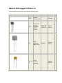
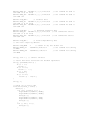
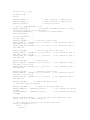
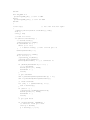
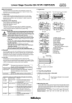
Adafruit GPS Logger Kit Parts List
Check to make sure your kit comes with the following parts.
Image
Name
Description
PCB
Printed
circuit board
IC1
3.3V linear
voltage
regulator,
250mA
current
Q1
PNP
transistor,
EBC pinout
0.1uF
C1, C2,
ceramic
C3
capacitor
Datasheet
Distributor Qty
Adafruit
1
MCP17003302E/TO
Digikey
Mouser
1
PN2907
Digikey
Mouser
1
Digikey
Mouser
3
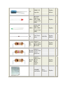
C4
100uF / 6V
capacitor
Digikey
Mouser
1
LED1
Red LED
Lite-On
LTL-1CHE
(or any 3mm
LED)
Digikey
1
LED2
Green LED
Lite-On
LTL-1CHG
(or any 3mm
LED)
Digikey
1
D1
3.6V Zener
diode
Digikey
Mouser
1
Digikey
Mouser
4
1N5227B
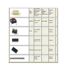
1/4W 5%
R1, R2,
1.0K resistor
R7,
Brown Black
R11
Red Gold
1/4W 5%
R3, R5, 4.7K resistor
R6, R8 yellow
purple red
4
1/4W 5%
10K resistor
R4, R9, Brown,
R10
Black,
Orange,
Gold
SD/MMC
card holder
Tyco
1734234-1
Digikey
Mouser
3
Digikey
1
EM406A
6 pin SMT
connector for
EM-406A
Either
Horizontal or
Vertical
JST
BM06BSRSSTB(LF)(SN)
Digikey
(V)
Digikey
(H)
1
RESET
6mm tactile
switch
B3F-1000
Digikey
Mouser
1
ICSP
6-pin ICSP
header
Digikey
Mouser
1
8 pin female
header (1x8)
Digikey
1
Digikey
Mouser
1
Digikey
Mouser
1
TXJMP Jumper/shunt
36 pin male
header
(1x36)
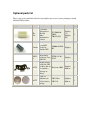
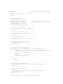
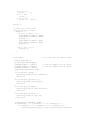
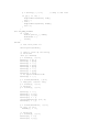
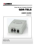
Optional parts list
These parts are not included in the kit, but might be necessary if you're planning to attach
different GPS modules.
Image
Name
Description
Datasheet
Distributor Qty
EB85A
8 pin SMT
connector for
EB-85A
Either
Horizontal or
Vertical
JST BM08BSRSSTB(LF)(SN)
Digikey
(V)
Digikey
(H)
8 pin SMT
Trimble header for
Trimble GPS
1
LPPB042NFSPDigikey
RC
20 pin SMT
A1035FTSH-111-01header for Tyco
D
L-DV
A1035-D
Digikey
BATT
Backup battery
holder for GPS
modules that do
Keystone 3000
not contain a
supercap or
battery
Digikey
Mouser
1
BATT
12mm 3V
Lithium coin
cell for battery
backup
Digikey
Mouser
1
CR1220 or
CR1216
Assembly
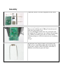
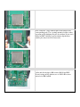
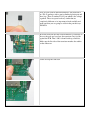
Check that you have all of the components for the shield.
Get ready by placing the PCB in a vise
Heat up your soldering iron to 700deg F, clean the tip and
make sure your sponge is wet
If you are building the shield from a kit, you'll notice that
the small 6-pin JST connector is pre-soldered. If you bought
just a PCB or are making your own, use surface mount
soldering techiques to solder the connector you are planning
to use.
Lets go!
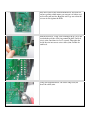
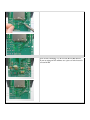
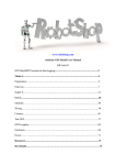
The first part we're going to solder is a 1K resistor. The
1.0K resistor is striped Brown Black Red Gold. Bend the
resistor into a staple as shown. The photo at left shows a
100 ohm resistor but just ignore the stripes.
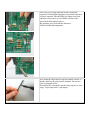
Place the resistor in the location marked R11. Resistors do
not have polarity which means you can put it in 'either way'
and it will work just fine. Bend the wire legs out so that the
resistor sits flat against the PCB.
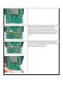
Turn the PCB over. Using your soldering iron tip, press and
heat both the pad (the silver ring around the hole) and lead
(wire) at the same time for 2 or 3 seconds. Then poke the
end of the wire into create a nice solder joint. Do this for
both leads.
Using your diagonal cutters, cut off the long leads just
above the solder joint.
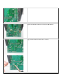
Repeat for the three other 1K resistors, R1 R2 and R7
Flip over the PCB and solder the 3 resistors.
Clip the three resistors' leads
Once you are feeling comfortable with the resistors, lets do
the SD card holder. The holder is surface mount (there are
no wires that go through the board) but the spacing is very
generous, so it wont be difficult.
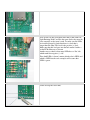
The holder has two bumps that 'snap' into place on the PCB.
Make sure that the bumps are engaged and the holder is
sitting flat.
The first step to soldering the holder is to 'tack' it in place.
On the sides are 4 large tabs. Heat both the pad and tab
together for 3 seconds and solder the tab down. Repeat for
all 4 tabs. When you're done you shouldn't be able to move
the holder.
Next, solder the 7 large leftmost pins of the holder to the
corresponding pads. Use a sparing amount of solder so that
you wont end up bridging two pins by accident. If you aren't
skilled at SMT soldering, you can simply skip the three
smaller pins, they're not at all necessary
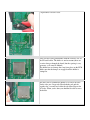
Flip the board over and let’s finish the resistors. Next place,
solder and clip the three 10K resistors R4 R9 and R10.
If you're using an NG Arduino, use a 1.0K-2.0K resistor
instead of a 10K for R10
Next are the remaining 4 4.7K resistors R3 R5 R6 and R8.
If you are using an NG arduino, use a piece of wire instead a
resistor for R6
Next is the 3.6V zener diode D1. Diodes are polarized,
unlike resistors. That means you have to place diodes
properly or they won’t work. To place the diode, look for
the black stripe on the red-glass body. Make sure when you
place the diode, the black stripe matches the white stripe on
the PCB silkscreen as shown. Solder and clip the diode in
place.
Next we will install the three yellow ceramic capacitors C1
C2 and C4. Ceramic capacitors are not polar so they can be
inserted either way and will work fine.
Place, solder and clip the capacitors.
Next are the red and green indicator LEDs. LED stands for
Light Emitting Diode, and like the zener diode, they must be
place correctly or they won’t work. To make sure the LEDs
are installed properly, check that there is a lead that is
longer than the other. This lead is the positive (+) lead.
Make sure that this lead goes into the hole marked with a +
on the PCB silkscreen, as shown.
Another way to check is that many LEDs have a 'flat' side
which marks the negative (-) side.
Place both LEDs, it doesn’t matter which color is LED1 and
which is LED2 but the code examples will assume that
LED1 is green.
Solder and clip the two LEDs.
Next we will solder in the PNP transistor. The transistor is
in a TO-92 package, with a semi-cylindrical plastic part and
three legs. There is another TO-92 part which is the voltage
regulator. These two parts look very similar but are
completely different so its important to look carefully and
make sure that you are going to solder in the part that says
PN2907A
Insert the transistor into the location marked Q1. Because of
the way the pads are layed out, the transistor won’t sit flat
against the PCB. That’s OK, it should stick up a little bit.
Make sure the flat side of the transistor matches the outline
on the silkscreen
Solder and clip the transistor
Next is the 3.3v voltage regulator and the electrolytic
capacitor C4. Electrolytic capacitors are polarized and must
be placed correctly. Like the LEDs, the longer lead of the
capacitor is the positive (+) lead. Make sure this lead is
placed in the hole marked with a +.
The regulator goes in just like the transistor.
Solder and clip both components.
Next, break the 36-pin header strip into smaller sections so
that the shield can be placed on the Arduino. You can use
pliers or diagonal cutters.
You will be able to perfectly snap the long strip into 2 8-pin
strips, 3 6-pin strips and 1 2-pin jumper.
Place the 2-pin strip in the location marked TXJMP (its near
the top). Make sure the long part of the header is sticking
up. Also place the 2x3 pin header into the location marked
ICSP
If you are planning to connect the shield to an FTDI USBTTL cable (see the user manual for more information) then
you should place one 6 pin strip in the header location
marked FTDI.
Place the button RESET. It is symmetrical and should snap
into place and sit flat against the PCB.
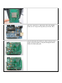
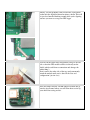
Solder in the headers. You may want to use tape to keep
them in place while you solder.
Place the 2 6-pin and 2 8-pin headers into your Arduino
(make sure it’s not powered up when you do this, OK?)
Slip the shield onto the Arduino as shown. The tips of the
headers should all match up and poke through the shield.
Solder all of the header pins.
Finally, you will probably want to install the 8-pin female
header into the digital breakout location as shown. This will
let you do a bunch of hacking around while you're figuring
out how you want to set up your GPS logger
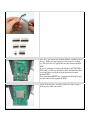
You can cut the foam sticky into quarters and peel off one
side so that the GPS module will not sit directly on the
shield (which could short a connection and damage the
whole thing!)
Don’t remove the other side of the tape and permanently
attach the module until you've done all the tests and
configuration! (just in case)
Place the jumper into the TXJMP jumper location and go
onto the user manual where you will learn how to wire up
your shield for testing and use.
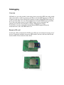
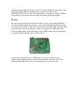
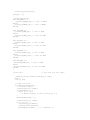
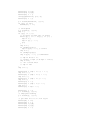
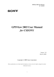
Picking a GPS Module
Overview
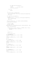
This shield requires a GPS module (sometimes called an "engine board" or "engine
module") to receive the timecode data from GPS satelites. There are dozens of GPS
modules on the market, each with slightly different specifications.
The Adafruit GPS shield v1.0 supports 4 popular hobbyist modules and is geared
specifically for the EM-406A: the required connector is already soldered on and ready to
go.
If you want to use a different module, check the parts list for the required connector as
they are not included.
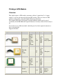
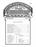
Supported modules
Image
Name
Description Power I/O
Sirf III
chipset
module
USGlobalSat with
EM-406A
antenna,
supercap,
lock
indicator
ETek EB85A
FV-M8
Tyco
A1035-D
Sirf III
chipset
module
with
antenna
56.5V
~3.3V
TTL
No backup
serial
battery required
4800
baud
3.35V
~3.3V
TTL
serial 5 Hz update!
38400
baud
3.3V
3.3V
TTL
serial
4800
baud
3.3V
3.3V
TTL
serial
4800
Trimble
Lassen iQ
Notes
Requires
battery &
antenna
baud
Connections
There are two parts of the shield: the GPS module interface and the SD card interface.
The SD card must be connected to the Arduino digital pins 13, 12, 11, and 10 for it to
work and so those pins are 'taken'. The GPS module interface does not have to be
connected to any -particular- pin so they are left free for you to jumper with common
wire..
The GPS interface is as follows:
TX - this is the transmit pin, data that comes from the GPS module with location data
RX - this is the receive pin, data that goes to the GPS module to configure it
PWR - this pin is connected to a transistor that controls power to the GPS. When this pin
is set to LOW the GPS module turns on and when the pin is set to HIGH the GPS turns
off.
L1 and L2 - these are the two red/green LEDs on the shield which can be used for
indicating whether data is being logged, if there is a GPS location lock, etc.
PPS - this is the GPS syncronized pulse clock, it pulses exactly once a second.
CD - this is actually part of the SD card interface, its a card detect switch and is
connected to ground when a card is in the holder. Its not really necessary but is included
in case you'd like to use it
WP - this is also part of the SD card interface, its a write protect switch and is connected
to ground when the little latch on the side of the SD card is set to 'lock'. Its not really
necessary but is included in case you'd like to use it
The only really important pins are PWR, TX and RX. Some modules work even when
RX is not connected to anything (floating) but many act kind of strange so I suggest
always connecting it up.
Make your wires
Cut three pieces of wire, two about 1" long and one 2" long.
Solder the two shorter ones to RX and TX. Solder the longer one to PWR.
Direct connect to computer
Overview
The first thing we will do is test the GPS by connecting it directly to the computer. This is useful
because sometimes you may want to get geolocative data directly into software.
You can connect with an FTDI cable or use your Arduino
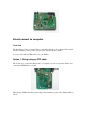
Option 1: Wiring using an FTDI cable
The easiest way to connect the GPS module to a computer is to remove it from the Arduino and
connect the GPSPWR line to ground.
Then plug in an FTDI cable and connect using a serial terminal program (or the Arduino IDE, see
below)
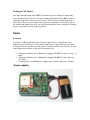
Option 2: Wiring using an Arduino
Remove the shield from the Arduino. Connect the GPS TX line to digital pin 1 and the RX line to
digital pin 0. Connect the PWR line to digital pin 2.
Remove chip
We want the GPS unit to talk to the FT232 chip on the arduino which will let us listen in using USB,
but the problem is that the Arduino chip (ATmega168) is in the way so we must remove it.
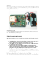
First, gently pry the Arduino microcontroller from its socket using a small flat screwdriver or similar.
Try to make sure the pins dont get bent. Put it in a safe place. Preferably in an anti-static bag.
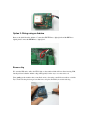
Next we will jumper digital i/o pin 2 to ground (LOW) which will make sure the GPS unit is turned on
when we connect up. Use a spare piece of wire and plug them into the empty socket as shown. Triple
check to make sure you have the jumper in the proper socket holes!
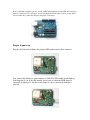
Plug in & power up
Plug the shield into the Arduino, and plug the GPS module into the little connector
Now connect the Arduino to your computer via USB. The GPS module should light up,
indicating that it’s on. If the GPS module doesn’t turn on, check the PWR jumper is
connected to digital pin 2, that the socket jumper is correct, and that the Arduino is
powered.
If possible, try to be near a window or outside. If possible, place the GPS module so that
the antenna (the large silver square) is outside and pointing upwards. This will make it
easier for it to get a location fix.
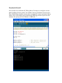
Connect and watch!
Lastly we will use the Arduino software to open up the USB serial port and listen in on
the GPS. Start up the software, make sure that the correct Serial Port is selected and click
on the Serial Monitor button. Select 4800 baud (unless you have an EB-86A which may
be 38400 by default)
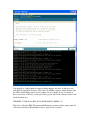
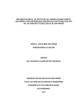
You should see a whole bunch of strange looking numbers and data, all the lines start
with $GP (Geographical Position). These lines are NMEA sentences which indicates that
the GPS is functioning properly and is sending data as it should. If you are outside or
have a clear view of the sky, you may be able to get fix data! In the sentences above, look
for the line that says:
$GPGRMC,211420.565,A,4042.3932,N,07400.4680,W,,260608,,*19
This line is called the RMC (Recommended Minimum) sentence and has pretty much all
of the most useful data. Each chunk of data is separated by a comma.
The first part 211420.565 is the current time GMT. The first two numbers 21 indicate the
hour (2100h, otherwise known as 9pm) the next two are the minute, the next two are the
seconds and finally the millseconds. So the time when this screenshot was taken is 9:14
pm and 20 seconds. The second part is the 'status code', if it is a V that means the data is
Void (invalid). If it is an A that means its Active (the GPS could get a lock/fix)
The next 4 pieces of data are the geolocation data. According to the GPS, my location is
4042.3932N (Latitude 40 degrees, 42.3932 minutes North) & 07400.4680W. (Longitude
74 degrees, 0.4680 minutes West) To look at this location in Google maps, type +40°
42.3932', -74° 00.4680' into the google maps search box (maps.google.com).
Unfortunately gmaps requires you to use +/- instead of NSWE notaion. N and E are
postive, S and W are negative. The next data is not used, the one after that is 260608
which is the current date (26th of June, 2008). Finally there is the *xx data which is used
as a data transfer checksum.
Once you get a fix using your GPS module, verify your location with google maps (or
some other mapping software). Remember that GPS is often only accurate to 5-10 meters
and worse if you're indoors or surrounded by tall buildings.
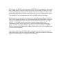
Testing
Overview
Once you've tested your GPS, its time to add the Arduino back in and show how to read
and parse data
Rewire
Remove the shield and take out the jumper in the chip socket. Re-place the Arduino chip,
making sure that no pins got bent and that the notch in the chip matches the notch in the
socket. Put the shield back on and re-wire it so that the jumpers now look like this:
TX should connect to pin 2, RX connects to pin 3 and PWR connects to pin 4.
Download & install libraries
We're going to use software serial to communicate with the GPS. If you have an NG with
a ATmega8 chip, you can use the SoftwareSerial library.
If you have an ATmega168, download and install the NewSoftSerial library from the
download page. Uncompress and place in the hardware/library directory under your
Arduino software installation.
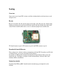
Upload test sketch
Download the GPStest_RMC sketch from the download page and upload it to the
Arduino.
This time, when the GPS module gets a fix, it will parse out the data and display it in
slightly more useful format. If you're planning to make locative projects that don't log to
the SD card you can stop now. This sketch can provide the backbone of most locative art
projects!
Datalogging
Overview
OK finally we get to the part that’s interesting, where you can log GPS data (and possibly
other sensor data as well) to a memory card. Please note that GPS logging to an SD card
is kind of at the edge of the ATmega168's abilities in terms of RAM and flash storage. It
works great but make sure to test any modifications and watch RAM usage in particular.
Try to reuse the buffer created to store NMEA strings, and use putstring() and
putstring_nl() instead of Serial.print() to display debugging data strings.
You'll need to start by reducing the Arduino library RAM footprint. Follow the
instructions here, and set the RX buffer to 32.
Format a SD card
You'll need a SD card formatted in FAT16, most SD cards are formatted correctly 'out of
the box'. Unplug the Arduino, remove the GPS module (for now) and insert the SD card
into the holder on the underside of the shield.
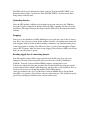
Download & Install
Next you'll need to install the AF_SDLog library. Uncompress it and place it in the
hardware/library directory under your Arduino software installation. If you have the
Wave Shield library installed, you may have to uninstall it (remove it from the library
folder) since it will conflict. Next download the GPSLogger sketch. Upload it to the
Arduino and open up the Serial Monitor at 4800 baud.
You should see the above. The logger starts up, initializes the SD card and creates a new
file called GPSLOG00.TXT. The next time it starts the file will be called
GPSLOG01.TXT, etc. If the SD card doesnt initialize, check that it is formatted FAT16,
try another card, etc. Once you have the SD card working, unplug the Arduino.
Re-wire
We need to rewire the shield one more time. Since we have pretty much no RAM left
over after including the SD_Log library we can't use the NewSoftSerial library. Instead
we will wire up the GPS so it shares the Serial connection with the USB-serial chip. That
means that every time the Arduino does a print() it is going to the USB connection as
well as the GPS module. Thats OK though, because GPS modules only pay attention to
very specific GPS commands and we won't confuse it.
Connect TX to pin 0, RX to pin 1,. PWR to pin 2, L2 to pin 3, and L1 to pin 4.
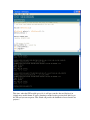
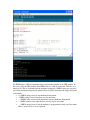
Connect up the Arduino again and watch the Serial Monitor. This time you will see
notification that GPS strings were received and properly written to the card
the $PSRF data is GPS customization data sent from the Arduino to the GPS module. In
this case it tells the GPS module what NMEA data we'd like it to transmit. Then we see a
bunch of #'s. This is feedback from the Arduino saying that a NMEA string was received,
passed the checksum and properly written. Here are all the characters the logger will print
as feedback:
• # - NMEA string received, checksummed and written
• - NMEA string received, but there was no checksum
• ~ - NMEA string received with checksum, but the checksum didnt match
• ! - NMEA string received but the data was too big for our buffer
• _ - NMEA string received, but the Arduino is programmed to only save data when
there is an active fix so it was ignored.
The LEDs will also give indication to whats going on. If the green LED (LED1) is lit,
that means that we have a location fix. If the red LED (LED2) is lit, that means data is
being written to the SD card.
Uploading sketches
Since the GPS module is talking to the Arduino on the same data pin as the USB chip,
you won’t be able to upload new sketches while the GPS is running. For that reason, the
shield has a TX jumper. Remove this jumper and the GPS will be disconnected from the
Arduino.
Stopping
Once you see the multitudes of LEDs blinking away for a bit and you feel like its time to
stop, here is the safest way to turn off the Arduino. Just like you wouldnt want to turn off
your computer while its in the middle of writing a document, you shouldnt cut the power
to the logger while its writing to the SD card as there is a risk of data corruption. Simply
remove the TX jumper when you want to stop logging. Wait till the red LED is not lit and
then you can safely remove power.
Reading logged data & converting formats
Now that you have turned off the logger and removed the SD card, place it in your
computer's SD card reader and open it with a text file reader (such as WordPad or
TextEdit). You will see those familiar NMEA sentences staring back at you!
You can now import this data into programs like Google Earth. Some programs require
special formatted data (which is quite annoying) and since this is such a problem, there is
a website devoted just to solving this problem called GPSvisualizer
(www.gpsvisualizer.com). Let’s go thru how to convert NMEA data to Google Earth
since that’s very popular. (You can also convert to other formats.). The defaults are pretty
good. I like uncompressed kml data but it doesnt really matter.
Under Upload your GPS data here you should Browse... and select the GPSLOGxx.TXT
you'd like to convert,
Click Create KML File and then you can download the KML file directly into Google
Earth for viewing
Customizing the GPS Logger
There's a few small things you can do to customize the GPS logger. You can turn on and
off specific NMEA sentences. For example
#define LOG_GSA 0 // satelite data
indicates that we do not want the GPS to emit satelite data. This saves memory card space and reduces
power consumption. To turn on $GPGSA data, simply set it to 1:
#define LOG_GSA 1 // satelite data
You can also set it to only log data when we have a location fix (0 means log eveything, 1 means only
log during fix)
#define LOG_RMC_FIXONLY 0 // log only when we get RMC's with fix?
You can turn WAAS on or off. This is an addition to North America where GPS can use ground
stations to get up to 3 meter radius precision. Set it to 0 to turn off.
#define USE_WAAS 1 // useful in US, but slower fix
You can also save a bunch of power by putting the Arduino (and even the GPS module) to sleep. This
doesnt make much sense if you need to log data once a second, which is the default. But if, say, you
dont mind only grabbing data once every 10 seconds or minute, it can reduce power consumption a
lot!
The SLEEPDELAY constant says how long the Arduino should sleep (do nothing, using no power)
between reads. Setting this to 0 means it never goes to sleep. 10 means sleep for 10 seconds. You can
use any # up to 255 seconds (4 1/4 minutes) If you have the LOG_RMC_FIXONLY variable set, it
will not go to sleep -until- there is a valid fix sentence.
#define SLEEPDELAY 0 // how long to sleep before reading another NMEA
sentence
If you want to really reduce power consumption, you can ask the Arduino to turn off the GPS module
while it sleeps. You pretty much have to use LOG_RMC_FIXONLY with this option because the
first 5 seconds after the GPS turns on is 'warm start' and you'll get about 5 no-fix data points before a
fix is acquired. Its an advanced power saving feature and may require some experimentation.
#define TURNOFFGPS 1 // probably only want to do this if the sleep
delay > 60 or so
Writing to CSV format
One other annoying thing about NMEA is that threes no real standard for embedding
sensor information into the data. So I wrote another sketch that will log RMC sentences,
split them up into nice comma-seperated-values (CSV) and also log analog inputs 0, 1
and 2 values. There’s pretty much no more space for doing funky sensor processing on
the Arduino but with the raw data, you can easily manipulate it on a computer by opening
it up in a spreadsheet or data analysis program.
Power
Overview
If you have a GPS module hooked up to your Arduino, there's a good chance you're
looking to run it on batteries or some other portable power supply. Here are some hints
on what you can use and how to reduce power. Current power test data: (Please post your
own findings to the forums so they can be integrated here)
•
•
•
2 Energizer Alkaline AA w/ Mintyboost, logging 1Hz RMC fix data, no sleep - 12
hours
2 Energizer Alkaline AA w/ Mintyboost, logging 1Hz RMC fix data, 30s sleep 16.5 hours
2 rechargeable AA w/Mintyboost, logging once a minute with sleep - 30 hours
Power supplies
9V battery
These are easy enough, pair it with a battery clip or holder with a 2.1mm barrel jack and
you can simply run the entire system off of this. Most 9V provide about 400mA-hours of
current (~5 hours of run time)
Lithium battery pack
A rechargeable lithium ion battery back that sits underneath the Arduino. Can provide
0.65 * the lithium battery mAh capacity
Reducing power requirements
There's three things that use up power in the GPS logger: the Arduino, the GPS module and the SD
card
•
•
•
•
The Arduino chip is always using about 10mA of current, maybe a little more if
there are LEDs. You can reduce this a lot by making it go to sleep
The USB chip uses about 10mA as well. If you dont have a USB cable plugged
in, this will save you a bit of power
The GPS module uses between 20mA and 60mA of current, depending on
whether it is trying to acquire a lock or whether it is merely tracking. You can
reduce this by using the GPSPWR pin to turn the GPS off between reports.
The SD card uses 20mA but only when writing data. You can reduce this by
sleeping between reports and only logging fix data from the GPS which translates
to less data written.
The "log everything all the time" configuration draws about 75mA
The "sleep for 10 seconds between reads but don't turn off the GPS" draws about 65mA
If you are outside where the GPS can get a fix pretty quickly, you can use as little as
10mA on average by logging only once a minute and turning off the GPS between logs.
Code
GPS Parsing Test
// A simple sketch to read GPS data and parse the $GPRMC string
// see http://www.ladyada.net/make/gpsshield for more info
#include <NewSoftSerial.h>
NewSoftSerial mySerial =
#define powerpin 4
NewSoftSerial(2, 3);
#define GPSRATE 4800
//#define GPSRATE 38400
// GPS parser for 406a
#define BUFFSIZ 90 // plenty big
char buffer[BUFFSIZ];
char *parseptr;
char buffidx;
uint8_t hour, minute, second, year, month, date;
uint32_t latitude, longitude;
uint8_t groundspeed, trackangle;
char latdir, longdir;
char status;
void setup()
{
if (powerpin) {
pinMode(powerpin, OUTPUT);
}
pinMode(13, OUTPUT);
Serial.begin(GPSRATE);
mySerial.begin(GPSRATE);
// prints title with ending line break
Serial.println("GPS parser");
digitalWrite(powerpin, LOW);
// pull low to turn on!
}
void loop()
{
uint32_t tmp;
Serial.print("\n\rread: ");
readline();
// check if $GPRMC (global positioning fixed data)
if (strncmp(buffer, "$GPRMC",6) == 0) {
// hhmmss time data
parseptr = buffer+7;
tmp = parsedecimal(parseptr);
hour = tmp / 10000;
minute = (tmp / 100) % 100;
second = tmp % 100;
parseptr = strchr(parseptr, ',') + 1;
status = parseptr[0];
parseptr += 2;
// grab latitude & long data
// latitude
latitude = parsedecimal(parseptr);
if (latitude != 0) {
latitude *= 10000;
parseptr = strchr(parseptr, '.')+1;
latitude += parsedecimal(parseptr);
}
parseptr = strchr(parseptr, ',') + 1;
// read latitude N/S data
if (parseptr[0] != ',') {
latdir = parseptr[0];
}
//Serial.println(latdir);
// longitude
parseptr = strchr(parseptr, ',')+1;
longitude = parsedecimal(parseptr);
if (longitude != 0) {
longitude *= 10000;
parseptr = strchr(parseptr, '.')+1;
longitude += parsedecimal(parseptr);
}
parseptr = strchr(parseptr, ',')+1;
// read longitude E/W data
if (parseptr[0] != ',') {
longdir = parseptr[0];
}
// groundspeed
parseptr = strchr(parseptr, ',')+1;
groundspeed = parsedecimal(parseptr);
// track angle
parseptr = strchr(parseptr, ',')+1;
trackangle = parsedecimal(parseptr);
// date
parseptr = strchr(parseptr, ',')+1;
tmp = parsedecimal(parseptr);
date = tmp / 10000;
month = (tmp / 100) % 100;
year = tmp % 100;
Serial.print("\nTime: ");
Serial.print(hour, DEC); Serial.print(':');
Serial.print(minute, DEC); Serial.print(':');
Serial.println(second, DEC);
Serial.print("Date: ");
Serial.print(month, DEC); Serial.print('/');
Serial.print(date, DEC); Serial.print('/');
Serial.println(year, DEC);
Serial.print("Lat: ");
if (latdir == 'N')
Serial.print('+');
else if (latdir == 'S')
Serial.print('-');
Serial.print(latitude/1000000, DEC); Serial.print('\°', BYTE);
Serial.print(' ');
Serial.print((latitude/10000)%100, DEC); Serial.print('\'');
Serial.print(' ');
Serial.print((latitude%10000)*6/1000, DEC); Serial.print('.');
Serial.print(((latitude%10000)*6/10)%100, DEC);
Serial.println('"');
Serial.print("Long: ");
if (longdir == 'E')
Serial.print('+');
else if (longdir == 'W')
Serial.print('-');
Serial.print(longitude/1000000, DEC); Serial.print('\°', BYTE);
Serial.print(' ');
Serial.print((longitude/10000)%100, DEC); Serial.print('\'');
Serial.print(' ');
Serial.print((longitude%10000)*6/1000, DEC); Serial.print('.');
Serial.print(((longitude%10000)*6/10)%100, DEC);
Serial.println('"');
}
//Serial.println(buffer);
}
uint32_t parsedecimal(char *str) {
uint32_t d = 0;
while (str[0] != 0) {
if ((str[0] > '9') || (str[0] < '0'))
return d;
d *= 10;
d += str[0] - '0';
str++;
}
return d;
}
void readline(void) {
char c;
buffidx = 0; // start at begninning
while (1) {
c=mySerial.read();
if (c == -1)
continue;
Serial.print(c);
if (c == '\n')
continue;
if ((buffidx == BUFFSIZ-1) || (c == '\r')) {
buffer[buffidx] = 0;
return;
}
buffer[buffidx++]= c;
}
}
GPS Basic Logging Sketch
// this is a generic logger that does checksum testing so the data
written should be always good
// Assumes a sirf III chipset logger attached to pin 0 and 1
#include
#include
#include
#include
"AF_SDLog.h"
"util.h"
<avr/pgmspace.h>
<avr/sleep.h>
// power saving modes
#define SLEEPDELAY 0
another NMEA sentence
#define TURNOFFGPS 0
sleep delay > 60 or so
#define LOG_RMC_FIXONLY 1
// how long to sleep before reading
// probably only want to do this if the
// log only when we get RMC's with fix?
AF_SDLog card;
File f;
#define led1Pin 4
#define led2Pin 3
#define powerPin 2
// LED1 connected to digital pin 4
// LED2 connected to digital pin 3
// GPS power control
// set the RX_BUFFER_SIZE to 32!
#define BUFFSIZE 75
// we buffer one NMEA sentense at a time,
83 bytes is longer than the max length
char buffer[BUFFSIZE];
// this is the double buffer
uint8_t bufferidx = 0;
#define LOG_RMC 1
// essential location data
#define RMC_ON
"$PSRF103,4,0,1,1*21\r\n" // the command we send to
turn RMC on (1 hz rate)
//#define RMC_ON
"$PSRF103,4,0,10,1*11\r\n" // 1/30 hz
#define RMC_OFF "$PSRF103,4,0,0,1*20\r\n" // the command we send to
turn RMC off
#define LOG_GGA
0
// contains fix, hdop & vdop data
#define GGA_ON
"$PSRF103,0,0,1,1*25\r\n"
turn GGA on (1 hz rate)
#define GGA_OFF "$PSRF103,0,0,0,1*24\r\n"
turn GGA off
#define LOG_GSA 0
// satelite data
#define GSA_ON
"$PSRF103,2,0,1,1*27\r\n"
turn GSA on (1 hz rate)
#define GSA_OFF "$PSRF103,2,0,0,1*26\r\n"
turn GSA off
// the command we send to
// the command we send to
// the command we send to
// the command we send to
#define LOG_GSV 0
// detailed satellite data
#define GSV_ON
"$PSRF103,3,0,1,1*26\r\n" // the command we send to
turn GSV on (1 hz rate)
#define GSV_OFF "$PSRF103,3,0,0,1*27\r\n" // the command we send to
turn GSV off
#define LOG_GLL 0
// Loran-compatibility data
// this isnt output by default
#define USE_WAAS
#define WAAS_ON
on WAAS
#define WAAS_OFF
off WAAS
1
// useful in US, but slower fix
"$PSRF151,1*3F\r\n"
// the command for turning
"$PSRF151,0*3E\r\n"
// the command for turning
uint8_t fix = 0; // current fix data
// read a Hex value and return the decimal equivalent
uint8_t parseHex(char c) {
if (c < '0')
return 0;
if (c <= '9')
return c - '0';
if (c < 'A')
return 0;
if (c <= 'F')
return (c - 'A')+10;
}
uint8_t i;
// blink out an error code
void error(uint8_t errno) {
while(1) {
for (i=0; i<errno; i++)
digitalWrite(led1Pin,
digitalWrite(led2Pin,
delay(100);
digitalWrite(led1Pin,
digitalWrite(led2Pin,
delay(100);
}
for (; i<10; i++) {
delay(200);
}
{
HIGH);
HIGH);
LOW);
LOW);
}
}
void setup()
// run once, when the sketch starts
{
WDTCSR |= (1 << WDCE) | (1 << WDE);
WDTCSR = 0;
Serial.begin(4800);
putstring_nl("GPSlogger");
pinMode(led1Pin, OUTPUT);
pinMode(led2Pin, OUTPUT);
pinMode(powerPin, OUTPUT);
digitalWrite(powerPin, LOW);
// sets the digital pin as output
// sets the digital pin as output
if (!card.init_card()) {
putstring_nl("Card init. failed!");
error(1);
}
if (!card.open_partition()) {
putstring_nl("No partition!");
error(2);
}
if (!card.open_filesys()) {
putstring_nl("Can't open filesys");
error(3);
}
if (!card.open_dir("/")) {
putstring_nl("Can't open /");
error(4);
}
strcpy(buffer, "GPSLOG00.TXT");
for (buffer[6] = '0'; buffer[6] <= '9'; buffer[6]++) {
for (buffer[7] = '0'; buffer[7] <= '9'; buffer[7]++) {
//putstring("\n\rtrying to open ");Serial.println(buffer);
f = card.open_file(buffer);
if (!f)
break;
// found a file!
card.close_file(f);
}
if (!f)
break;
}
if(!card.create_file(buffer)) {
putstring("couldnt create "); Serial.println(buffer);
error(5);
}
f = card.open_file(buffer);
if (!f) {
putstring("error opening "); Serial.println(buffer);
card.close_file(f);
error(6);
}
putstring("writing to "); Serial.println(buffer);
putstring_nl("ready!");
delay(1000);
putstring("\r\n");
#if USE_WAAS == 1
putstring(WAAS_ON); // turn on WAAS
#else
putstring(WAAS_OFF; // turn on WAAS
#endif
#if LOG_RMC == 1
putstring(RMC_ON); // turn on RMC
#else
putstring(RMC_OFF); // turn off RMC
#endif
#if LOG_GSV == 1
putstring(GSV_ON); // turn on GSV
#else
putstring(GSV_OFF); // turn off GSV
#endif
#if LOG_GSA == 1
putstring(GSA_ON); // turn on GSA
#else
putstring(GSA_OFF); // turn off GSA
#endif
#if LOG_GGA == 1
putstring(GGA_ON); // turn on GGA
#else
putstring(GGA_OFF); // turn off GGA
#endif
}
void loop()
// run over and over again
{
//Serial.println(Serial.available(), DEC);
char c;
uint8_t sum;
// read one 'line'
if (Serial.available()) {
c = Serial.read();
//Serial.print(c, BYTE);
if (bufferidx == 0) {
while (c != '$')
c = Serial.read(); // wait till we get a $
}
buffer[bufferidx] = c;
//Serial.print(c, BYTE);
if (c == '\n') {
//putstring_nl("EOL");
//Serial.print(buffer);
buffer[bufferidx+1] = 0; // terminate it
if (buffer[bufferidx-4] != '*') {
// no checksum?
Serial.print('*', BYTE);
bufferidx = 0;
return;
}
// get checksum
sum = parseHex(buffer[bufferidx-3]) * 16;
sum += parseHex(buffer[bufferidx-2]);
// check checksum
for (i=1; i < (bufferidx-4); i++) {
sum ^= buffer[i];
}
if (sum != 0) {
//putstring_nl("Cxsum mismatch");
Serial.print('~', BYTE);
bufferidx = 0;
return;
}
// got good data!
if (strstr(buffer, "GPRMC")) {
// find out if we got a fix
char *p = buffer;
p = strchr(p, ',')+1;
p = strchr(p, ',')+1;
// skip to 3rd item
if (p[0] == 'V') {
digitalWrite(led1Pin, LOW);
fix = 0;
} else {
digitalWrite(led1Pin, HIGH);
fix = 1;
}
}
#if LOG_RMC_FIXONLY
if (!fix) {
Serial.print('_', BYTE);
bufferidx = 0;
return;
}
#endif
// rad. lets log it!
Serial.print(buffer);
Serial.print('#', BYTE);
digitalWrite(led2Pin, HIGH);
output
// sets the digital pin as
if(card.write_file(f, (uint8_t *) buffer, bufferidx) !=
bufferidx) {
putstring_nl("can't write!");
return;
}
digitalWrite(led2Pin, LOW);
bufferidx = 0;
// turn off GPS module?
if (TURNOFFGPS) {
digitalWrite(powerPin, HIGH);
}
sleep_sec(SLEEPDELAY);
digitalWrite(powerPin, LOW);
return;
}
bufferidx++;
if (bufferidx == BUFFSIZE-1) {
Serial.print('!', BYTE);
bufferidx = 0;
}
} else {
}
}
void sleep_sec(uint8_t x) {
while (x--) {
// set the WDT to wake us up!
WDTCSR |= (1 << WDCE) | (1 << WDE); // enable watchdog & enable
changing it
WDTCSR = (1<< WDE) | (1 <<WDP2) | (1 << WDP1);
WDTCSR |= (1<< WDIE);
set_sleep_mode(SLEEP_MODE_PWR_DOWN);
sleep_enable();
sleep_mode();
sleep_disable();
}
}
SIGNAL(WDT_vect) {
WDTCSR |= (1 << WDCE) | (1 << WDE);
WDTCSR = 0;
}
GPS CSV Logging Sketch
// Saves RMC sentences in CSV format with data from 3 analog sensors. Not tested with 328P chip.
// this is a generic logger that does checksum testing so the data
written should be always good
// Assumes a sirf III chipset logger attached to pin 0 and 1
#include "AF_SDLog.h"
#include "util.h"
#include <avr/pgmspace.h>
#define isdigit(x) ( x >= '0' && x <= '9')
extern uint16_t _end;
AF_SDLog card;
File f;
#define led1Pin 4
#define led2Pin 3
#define powerpin 2
// LED1 connected to digital pin 4
// LED2 connected to digital pin 3
// GPS power control
// set the RX_BUFFER_SIZE to 32!
#define BUFFSIZE 73
// we buffer one NMEA sentense at a time,
83 bytes is longer than the max length
char buffer[BUFFSIZE];
// this is the double buffer
char buffer2[12];
uint8_t bufferidx = 0;
uint32_t tmp;
#define LOG_RMC 1
// essential location data
#define RMC_ON
"$PSRF103,4,0,1,1*21\r\n" // the command we send to
turn RMC on (1 hz rate)
#define RMC_OFF "$PSRF103,4,0,0,1*20\r\n" // the command we send to
turn RMC off
#define LOG_GGA 0
// contains fix, hdop & vdop data
#define GGA_ON
"$PSRF103,0,0,1,1*25\r\n"
// the command we send to
turn GGA on (1 hz rate)
#define GGA_OFF "$PSRF103,0,0,0,1*24\r\n"
// the command we send to
turn GGA off
#define LOG_GSA 0
// satelite data
#define GSA_ON
"$PSRF103,2,0,1,1*27\r\n"
turn GSA on (1 hz rate)
#define GSA_OFF "$PSRF103,2,0,0,1*26\r\n"
turn GSA off
// the command we send to
// the command we send to
#define LOG_GSV 0
// detailed satellite data
#define GSV_ON
"$PSRF103,3,0,1,1*26\r\n" // the command we send to
turn GSV on (1 hz rate)
#define GSV_OFF "$PSRF103,3,0,0,1*27\r\n" // the command we send to
turn GSV off
#define LOG_GLL 0
// Loran-compatibility data
// this isnt output by default
#define USE_WAAS
#define WAAS_ON
on WAAS
#define WAAS_OFF
off WAAS
1
// useful in US, but slower fix
"$PSRF151,1*3F\r\n"
// the command for turning
"$PSRF151,0*3E\r\n"
// the command for turning
#define LOG_RMC_FIXONLY 1 // log only when we get RMC's with fix?
uint8_t fix = 0; // current fix data
// read a Hex value and return the decimal equivalent
uint8_t parseHex(char c) {
if (c < '0')
return 0;
if (c <= '9')
return c - '0';
if (c < 'A')
return 0;
if (c <= 'F')
return (c - 'A')+10;
}
uint8_t i;
// blink out an error code
void error(uint8_t errno) {
while(1) {
for (i=0; i<errno; i++)
digitalWrite(led1Pin,
digitalWrite(led2Pin,
delay(100);
digitalWrite(led1Pin,
digitalWrite(led2Pin,
delay(100);
}
for (; i<10; i++) {
delay(200);
}
}
}
{
HIGH);
HIGH);
LOW);
LOW);
void setup()
{
Serial.begin(4800);
putstring_nl("GPSlogger");
pinMode(led1Pin, OUTPUT);
pinMode(led2Pin, OUTPUT);
pinMode(powerpin, OUTPUT);
digitalWrite(powerpin, LOW);
// run once, when the sketch starts
// sets the digital pin as output
// sets the digital pin as output
if (!card.init_card()) {
putstring_nl("Card init. failed!");
error(1);
}
if (!card.open_partition()) {
putstring_nl("No partition!");
error(2);
}
if (!card.open_filesys()) {
putstring_nl("Can't open filesys");
error(3);
}
if (!card.open_dir("/")) {
putstring_nl("Can't open /");
error(4);
}
strcpy(buffer, "GPSLOG00.TXT");
for (buffer[6] = '0'; buffer[6] <= '9'; buffer[6]++) {
for (buffer[7] = '0'; buffer[7] <= '9'; buffer[7]++) {
//putstring("\n\rtrying to open ");Serial.println(buffer);
f = card.open_file(buffer);
if (!f)
break;
// found a file!
card.close_file(f);
}
if (!f)
break;
}
if(!card.create_file(buffer)) {
putstring("couldnt create "); Serial.println(buffer);
error(5);
}
f = card.open_file(buffer);
if (!f) {
putstring("error opening "); Serial.println(buffer);
card.close_file(f);
error(6);
}
putstring("writing to "); Serial.println(buffer);
putstring_nl("ready!");
// write header
strncpy_P(buffer,
PSTR("time,lat,long,speed,date,sens0,sens1,sens2\n"), 43);
Serial.print(buffer);
if(card.write_file(f, (uint8_t *) buffer, 43) != 43) {
putstring_nl("can't write!");
return;
}
delay(1000);
putstring("\r\n");
#if USE_WAAS == 1
putstring(WAAS_ON); // turn on WAAS
#else
putstring(WAAS_OFF); // turn on WAAS
#endif
#if LOG_RMC == 1
putstring(RMC_ON); // turn on RMC
#else
putstring(RMC_OFF); // turn off RMC
#endif
#if LOG_GSV == 1
putstring(GSV_ON); // turn on GSV
#else
putstring(GSV_OFF); // turn off GSV
#endif
#if LOG_GSA == 1
putstring(GSA_ON); // turn on GSA
#else
putstring(GSA_OFF); // turn off GSA
#endif
#if LOG_GGA == 1
putstring(GGA_ON); // turn on GGA
#else
putstring(GGA_OFF); // turn off GGA
#endif
}
void loop()
// run over and over again
{
//Serial.println(Serial.available(), DEC);
char c;
uint8_t sum;
// read one 'line'
if (Serial.available()) {
c = Serial.read();
//Serial.print(c, BYTE);
if (bufferidx == 0) {
while (c != '$')
c = Serial.read(); // wait till we get a $
}
buffer[bufferidx] = c;
//Serial.print(c, BYTE);
if (c == '\n') {
//putstring_nl("EOL");
//Serial.print(buffer);
buffer[bufferidx+1] = 0; // terminate it
if (buffer[bufferidx-4] != '*') {
// no checksum?
Serial.print('*', BYTE);
bufferidx = 0;
return;
}
// get checksum
sum = parseHex(buffer[bufferidx-3]) * 16;
sum += parseHex(buffer[bufferidx-2]);
// check checksum
for (i=1; i < (bufferidx-4); i++) {
sum ^= buffer[i];
}
if (sum != 0) {
//putstring_nl("Cxsum mismatch");
Serial.print('~', BYTE);
bufferidx = 0;
return;
}
// got good data!
if (strstr(buffer, "GPRMC")) {
// find out if we got a fix
char *p = buffer;
p = strchr(p, ',')+1;
p = strchr(p, ',')+1;
// skip to 3rd item
if (p[0] == 'V') {
digitalWrite(led1Pin, LOW);
fix = 0;
} else {
digitalWrite(led1Pin, HIGH);
fix = 1;
}
}
#if LOG_RMC_FIXONLY
if (!fix) {
Serial.print('_', BYTE);
bufferidx = 0;
return;
}
#endif
// rad. lets print it!
Serial.print(buffer);
// time to clean up the string
// find time
char *p = buffer;
p = strchr(p, ',')+1;
buffer[0] = p[0];
buffer[1] = p[1];
buffer[2] = ':';
buffer[3] = p[2];
buffer[4] = p[3];
buffer[5] = ':';
buffer[6] = p[4];
buffer[7] = p[5];
// we ignore milliseconds
buffer[8] = ',';
p = strchr(buffer+8, ',')+1;
// skip past 'active' flag
p = strchr(p, ',')+1;
// find lat
p = strchr(p, ',')+1;
buffer[9] = '+';
buffer[10] = p[0];
buffer[11] = p[1];
buffer[12] = ' ';
strncpy(buffer+13, p+2, 7);
buffer[20] = ',';
p = strchr(buffer+21, ',')+1;
if (p[0] == 'S')
buffer[9] = '-';
// find long
p = strchr(p, ',')+1;
buffer[21] = '+';
buffer[22] = p[0];
buffer[23] = p[1];
buffer[24] = p[2];
buffer[25] = ' ';
strncpy(buffer+26, p+3, 7);
buffer[33] = ',';
p = strchr(buffer+34, ',')+1;
if (p[0] == 'W')
buffer[21] = '-';
// find speed
p = strchr(p, ',')+1;
tmp = 0;
if (p[0] != ',') {
// ok there is some sort of speed
while (p[0] != '.' && p[0] != ',') {
tmp *= 10;
tmp += p[0] - '0';
p++;
}
tmp *= 10;
if (isdigit(p[1]))
tmp += p[1] - '0'; // tenths
tmp *= 10;
if (isdigit(p[2]))
tmp += p[2] - '0'; // hundredths
// tmp is knots * 100
// convert to mph (1.15 mph = 1 knot)
tmp *= 115;
// -OR- convert km/h
// tmp *= 185
}
tmp /= 100;
buffer[34] = (tmp / 10000) + '0';
tmp %= 10000;
buffer[35] = (tmp / 1000) + '0';
tmp %= 1000;
buffer[36] = (tmp / 100) + '0';
tmp %= 100;
buffer[37] = '.';
buffer[38] = (tmp / 10) + '0';
tmp %= 10;
buffer[39] = tmp + '0';
buffer[40] = ',';
p = strchr(p, ',')+1;
// skip past bearing
p = strchr(p, ',')+1;
// get date into 2001-01-31 style
buffer[41] = '2';
buffer[42] = '0';
buffer[43] = p[4];
buffer[44] = p[5];
buffer[45] = '-';
buffer[46]
buffer[47]
buffer[48]
buffer[49]
buffer[50]
buffer[51]
=
=
=
=
=
=
p[2];
p[3];
'-';
p[0];
p[1];
',';
// add sensor data after here
// read analog 0 pin
tmp = analogRead(0);
buffer[52] = (tmp / 1000) + '0'; tmp %= 1000;
buffer[53] = (tmp / 100) + '0'; tmp %= 100;
buffer[54] = (tmp / 10) + '0'; tmp %= 10;
buffer[55] = (tmp) + '0';
buffer[56] = ',';
// read analog 1 pin
tmp = analogRead(1);
buffer[57] = (tmp / 1000) + '0'; tmp %= 1000;
buffer[58] = (tmp / 100) + '0'; tmp %= 100;
buffer[59] = (tmp / 10) + '0'; tmp %= 10;
buffer[60] = (tmp) + '0';
buffer[61] = ',';
// read analog 2 pin
tmp = analogRead(2);
buffer[62] = (tmp / 1000) + '0'; tmp %= 1000;
buffer[63] = (tmp / 100) + '0'; tmp %= 100;
buffer[64] = (tmp / 10) + '0'; tmp %= 10;
buffer[65] = (tmp) + '0';
buffer[66] = '\n';
buffer[67] = 0;
Serial.print(buffer);
digitalWrite(led2Pin, HIGH);
// sets the digital pin as
output
if(card.write_file(f, (uint8_t *) buffer, strlen(buffer)) !=
strlen(buffer)) {
putstring_nl("can't write!");
return;
}
digitalWrite(led2Pin, LOW);
bufferidx = 0;
return;
}
bufferidx++;
if (bufferidx == BUFFSIZE-1) {
Serial.print('!', BYTE);
bufferidx = 0;
}
}
}