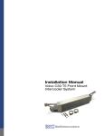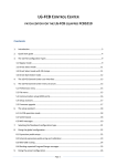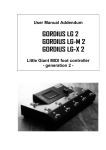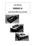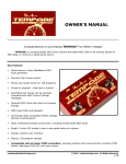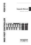
1
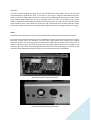
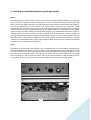
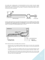
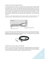
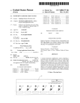
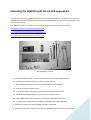
Extending the FCB1010 with the LG-FCB upgrade kit.
This manual covers the upgrade procedure for the LG-FCB upgrade kit. A separate user manual is
available with detailed info about the functionality provided by the kit, and how to program it using
LG-FCB ControlCenter.
The upgrade is shown in a small series of videos available on YouTube. Here are the links:
http://www.youtube.com/watch?v=SH1VJJxa7yw
http://www.youtube.com/watch?v=qKggvYpDmAM
http://www.youtube.com/watch?v=UvS2vfm_-Vk
the upgrade kit contents
1a. LG-FCB connector board, contains a USB connector and a 7-pins MIDI connector
1b. LG-FCB main controller board, the “brains” of the upgrade
2. special FCB1010 firmware for 2-way communication with LG-FB board
3a. 4 screws to install the main board
3b. 2 metal hex spacers and 2 plastic spacers for mounting the main board
4a. USB connection cable between connector board and main board
4b. Power+MIDI connection cable between connector board and main board
4c. Communication cable between FCB1010 main board and LG-FCB main board
5. Cable ties to attach the internal power connectors and leads
6. 2 solderless connectors with wire for connecting FCB1010 power with the LG-FCB boards
1
The FCB1010 after upgrading
2
The optional expression pedal input board
Along with the upgrade kit shown above, you can also install an optional expression pedal input
board. The new board, which connects to the LG-FCB main board using a small 4-wire cable, is
mechanically compatible with the original jack board, so replacing the board is very simple. More info
about this board is given in topic 4 of this manual.
original and new jack boards
new input board installed next to the connector board
3
1. Opening the FCB1010 housing
Lay the FCB1010 upside down on a soft surface, disconnect the power cord, and remove the 16 black
screws which hold the bottom cover. Now you can flip the bottom plate over in order to access the
FCB1010 internals. Attention, the bottom plate is still connected to the housing with a ground wire,
but you can flip it over without disconnecting this wire.
the 16 screws to remove
the opened housing, with ground wire attached
4
2. Upgrading the FCB1010 firmware EPROM
Why ?
With the LG-FCB board installed, the original FCB1010 functionality is replaced with the extended LGFCB feature set. One of the advantages is that the LG-FCB firmware can be easily updated through
USB, which is not the case with the original FCB1010 firmware. To accomplish this, the original
FCB1010 firmware is replaced with very basic firmware, which turns the FCB1010 into a “slave” for
the LG-FCB board. All switch clicks are simply forwarded to the board, and all control over the switch
LEDs is taken over by the LG-FCB board. The FCB1010 slave firmware EPROM which accomplishes this
is included in the upgrade package.
How ?
Behringer provides following PDF document about upgrading the FCB1010 firmware chip:
http://www.ossandust.be/files/Upgrade_Manual_FCB1010_Rev_A.pdf
You can also have a look at the first video mentioned on page 1 of this manual.
Here’s a short description of the procedure:
-
Remove all hotglue which holds the original EPROM in place. This is the hardest part. Make
sure not to damage the electronics board while peeling of the glue dots.
-
When all glue is removed, lift the EPROM out of its socket by prying a small screwdriver
underneath the chip at both sides alternately.
-
Before trying to insert the new chip, make sure its pins are in a perfect 90° angle. A “fresh”
chip has its pins bent outwards a little. You can bend all pins of one side slightly inwards by
placing the chip sideways on a table and gently applying pressure.
-
Gently insert the chip in the socket, paying attention to the correct orientation. The chip has
a small notch on one of its small sides. The socket has a similar notch. Align both notches to
have the correct orientation; don’t use the printed label on the chip as a reference. While
inserting the chip, make sure all pins are correctly aligned, so that they don’t get bent.
straightening the pins
the installed PROM
Important : before proceeding with the next step, please test if the firmware upgrade has succeeded!
(see also the first video mentioned before). Apply power and see if the display shows “---“, which
means that the FCB1010 has started correctly with the upgraded firmware.
5
3. Installing the new MIDI/USB connector board
What ?
One of the most interesting add-ons of the LG-FCB board is its USB capability. You can now download
setups and even firmware updates through USB. The original FCB1010 is depending on third-party
MIDI-USB interfaces, which regularly turn out to be incompatible with the SysEx messages used by
the FCB1010.
In order to avoid difficult modifications of the metal housing, we decided to replace the 2 original
MIDI connectors with one USB connector and one 7-pins MIDI connector. The 7-pins connector
combines MIDI IN, MIDI OUT, and phantom power functionality. It is compatible with a regular MIDI
OUT connector, while 2 of the normally unconnected pins are now used for MIDI IN. The 2 extra pins
can optionally be used to apply phantom power. Details about the connector pinning are shown in
the drawing below. Details about phantom powering are covered in a later chapter.
The regular FCB1010 required a MIDI IN connection for doing patchdumps from computer. Since the
LG-FCB board has USB for this, you probably won’t miss the MIDI IN connector. Just use a regular 5pins MIDI cable and treat the 7-pins connector as a regular MIDI OUT. If however you do need extra
MIDI IN capability (for adding more MIDI devices earlier in the MIDI chain), you will need to make a
conversion cable to go from two 5-pins IN/OUT connectors to one single 7-pins, using the pinning
info above.
Jumper settings?
On the connector board you will see 2 jumpers. When you leave them on their original position, you
will have all MIDI IN/MIDI OUT/phantom power functionality described above. Both jumpers can be
moved to the alternative position in one specific scenario: if your connected MIDI device supports
this, you can use pins 1 & 3 of the connector for applying phantom power, instead of using the
default pins 6 & 7. This allows you to use a regular 5-pins MIDI cable instead of a less common 7-pins
cable. In this scenario, no MIDI IN functionality is available.
pins 1 & 3 = MIDI IN (default)
Pins 1 & 3 = phantom power
6
Attention:
in order to avoid damaging your gear, do not use this alternative wiring unless you are sure that the
connected device supports this! Also, if you want to use a 5-pins cable for both MIDI and power,
make sure that the used cable has all 5 pins wired. Since the MIDI standard only uses 3 of the 5 pins,
many cheaper MIDI cables have only 3 pins actually wired. The same is true when using a 7-pins
cable for both MIDI IN and MIDI OUT along with phantom power. Pins 6 & 7 of such cable are always
wired, however some 7-pins cables don’t have pins 1 & 3 wired. And one last obvious remark: always
move both jumpers simultaneously and keep them aligned, never mix 2 settings (one left, one right).
How ?
Installation of the electronics is shown in the second video, mentioned at the start of this manual.
The small LG-FCB connector board is an easy replacement of the original connector board. It reuses
the same 2 black screws for mounting. You will need cutting pliers when removing the original
connector board: it has a small ground wire soldered to another board, which you can simply cut. In
order to unplug the connector from the main board, you might need to remove some hot glue on the
connector first. Be careful not to damage the board or the connector while doing so. Later on we will
reuse this same FCB1010 main board connector for connection with the LG-FCB board.
mounted connector board, inside view
mounted connector board, outside view
7
4. Installing the optional expression pedal input board
What ?
The FCB1010 has 2 “switch output” jacks for controlling non-MIDI enabled amplifiers. Two internal
relays can close or open the contacts on the jacks. It is easy to confuse this with jack inputs which you
find on many other MIDI controllers, and which can be used to connect external expression pedals. If
you are not interested in the jack outputs, but would prefer 2 jack inputs for expression pedals
instead, you can install the optional expression pedal input board. This board digitizes any regular
expression pedal, and the LG-FCB board converts the pedal sweep into a continuous stream of MIDI
ControlChange messages. Adding this interface board gives you 4 independent expression pedals: 2
external ones next to the 2 internal expression pedals of the FCB1010. Each of the 4 pedals can
manage a different setting of the (MIDI-)controlled device. As you can read in the manual of the LGFCB editor, each single expression pedal can even control multiple settings simultaneously, each with
a different programmable sweep range. The expression pedal settings can be programmed globally
for all presets, or individually for each preset.
How ?
Installation of the expression pedal board is very straightforward. It is mechanically compatible with
the original FCB1010 jack board, so you can simply remove the original board (by removing the 2 nuts
and disconnecting the internal cable which plugs into the FCB1010 main board), and replace it with
the new board, reusing the washers and nuts of the original one. The short cable of the new input
board will plug into the LG-FCB main board. Once that board is installed, it will be obvious which
connector to use for this (see also the topic about “Making the connections” further below)
8
5. Installing the LG-FCB board
What ?
The LG-FCB board is the new “brain” of your floorboard. It fits inside the FCB1010, on top of one of
the large switch electronics boards. At one side, it connects to the original FCB1010 main board to
receive click events and control the LEDs and display. At the other side, it connects to the outside
world through the newly installed connector board.
Jumper settings?
The LG-FCB board contains 2 adjacent jumpers, which are related to the optional use of phantom
power. Indeed, you have 2 options for powering the board. One possibility is to reuse the FCB1010
power. With this option you simply keep powering the FCB1010 as you did before: through the mains
lead connected to the back of the floorboard. The LG-FCB board is connected to the internal power
leads, as described in detail in a next chapter. To use this option, simply keep the 2 jumpers on their
original position (see left side picture below)
A second option is to use phantom power. This option allows you to apply power to the LG-FCB
board through the 7-pins MIDI connector. This connection can not only power the LG-FCB board
itself, but also the FCB1010 electronics. This means that you no longer need to plug in a power lead
at the back side of the FCB1010. Just connect a 9V AC or DC adapter at the other side of your 7-pins
MIDI cable, and then this MIDI cable is the only cable running to your floorboard. In order to use this
phantom power option, move the 2 jumpers to their alternate position (right side picture below). See
the chapter about “making the connections” for a schematic drawing of the 2 powering options.
reuse FCB1010 power
supply phantom power
Remark: always install both jumpers in the same position: either left or right (as shown in the
pictures above). Never mix 2 different jumper positions, as this might result in a damaged power
adapter and/or FCB1010 transfo.
Remark: the additional jumper which you can see in the background at the left side of both pictures
is used for factory testing purposes only. Its position should never be changed.
9
How ?
You can reuse 4 existing attachment points to mount the LG-FCB board. 4 spacers are included in the
upgrade kit: 2 hex spacers replace 2 hex nuts, 2 plastic spacers are mounted reusing the original
screws. The picture below indicates the exact location of the 4 attachment points.
LG-FCB main board attachment points
close-up (backside view)
The special white plastic spacers are used to map the board mounting holes with the original
mounting points. As shown in the second video mentioned at the beginning of this manual, you can
first position the board and use its mounting screws to find the optimal placement angle of the 2
white spacers. Then remove the board again and fasten the spacers on their correct position, before
installing the board permanently.
10
6. Making the connections
Now we can insert all cables supplied with the upgrade kit. A short 4-lead wire goes from connector
board to main board. It carries the 2-way USB signal. Next, an 8-lead wire is connected between the
same two boards. This wire carries MIDI IN and OUT, and (optionally) phantom power. The remaining
wire, a longer 4-lead wire, goes from LG-FCB board to FCB1010 main board. The LG-FCB board has
two identical 4-pins connectors. Use the one which is in line with the 8-pins connector, so the one
closest to the edge. At the other side, plug the wire into the connector which was used by the
original connector board. You unplugged this cable in a previous step. Finally, in case you also have
installed an expression pedal input board, connect the small cable of that board with the remaining
4-pins connector on the LG-FCB main board.
Boards overview (top view inside FCB1010 housing) :
A = new connector board
B = original jack output board, or new expression pedal input board
C = new LG-FCB main board
D = original FCB1010 main board
Connections overview :
1a – 1b = USB between connector board and LG-FCB main board
2a – 2b = MIDI/power between connector board and LG-FCB main board
3a – 3b = communication between FCB1010 main board and LG-FCB main board
4a – 4b = original connection FCB1010 main board – jack board
5 = communication between LG-FCB main board and optional expression pedal input board
(leave connector 5 open when not using the expression pedal input board)
11
The trickiest part is applying power. As mentioned before we have 2 options: using the original
FCB1010 power, or using phantom power. The LG-FCB board has specific jumper settings to choose
between both options. In both cases we will need to interrupt the internal power leads in order to
connect them to the LG-FCB board.
The two original yellow wires carrying the low-voltage AC power for the FCB1010 main board will be
interrupted in order to supply power for the LG-FCB board too, or else in order to eliminate the builtin transformator and apply phantom power from the MIDI connector instead. The 2 options will be
shown in more detail on the following pages (topic 5.2 and 5.3)
Above schematic shows you all possible power connections :
-
Phantom power can be applied through the MIDI connector and enters the LG-FCB board
through the 8-pins cable. From there it runs to the 2 jumpers, as one of the possible power
sources.
-
The cut wires coming from the FCB1010 transfo enter the LG-FCB board through the 5-pins
spring terminal block, and go to the other side of the 2 jumpers as alternative power source.
-
The middle contacts of the 2 jumpers will contain the chosen power source, and are routed
both to the power input of the LG-FCB board and through the 5-pins spring terminal block to
the power input of the FCB1010 board.
12
6.1 Interconnecting power of the 2 main boards
First of all we need to interconnect the power input of the LG-FCB board and the FCB1010 main
board. We do this by cutting the 2 yellow power leads which run from FCB1010 transfo to the
FCB1010 main board (they carry a low voltage, something like 9 VAC. Don’t worry, our modifications
will never interfere with mains voltage!) Cut both yellow wires at about 3” (7.5cm), measured from
the main board. Now you can connect the 2 smallest ends coming from the FCB1010 main board
with the LG-FCB board, using the big green spring terminal block. Strip both wires and insert them in
the 2 rightmost contacts of the green connector (the contacts closest to the FCB1010 main board).
Since the wires carry AC voltage, which doesn’t have a polarity, it doesn’t matter in which order you
connect the wires, as long as you use the 2 rightmost contacts. Even when using DC phantom power
the polarity is still irrelevant, since both connected boards have a rectifier circuit which can handle
both DC polarities.
The connections with the terminal block are easy to make. Take a small screwdriver, and use it to
push the small plastic “handle” next to the contact firmly. Then guide the wire into the contact hole,
and release the handle. The wire will now be pinched into the contact – pull it to check that you have
a firm connection.
13
6.2 Power connection when using the FCB1010 power cord
This is the default way of powering the LG-FCB board. You just keep powering the FCB1010 as before,
using its mains cord connected to the back side. In order to do so, you need to connect the FCB1010
transfo output to the green LG-FCB connector. From there the power runs through the 2 jumpers to
the shared power inputs of both boards, which we wired in the previous step.
The transfo output is simply the other side of the 2 yellow wires which you cut previously. They are
too short to reach the green connector of the LG-FCB board. Therefore we have provided 2 short
pieces of extension wire, and a “pinch” connector which allows extending the 2 cut wires without
need for a soldering iron. One of the supplied cable ties can be used to strap the two floating
connectors together after making the connections (see picture 1 below). Then you can attach the
connectors to the housing using the second cable tie (see picture 2 below), so that everything is
safely secured and no stress is applied to the wire connections. Of course, if you have the necessary
tools, you can also choose to make a soldered connection instead of using the 2 pinch connectors.
14
6.3 Power connection when using phantom power
As mentioned in the previous topics, you can also choose to use phantom power, supplied through
the 7-pins MIDI connector. In that case, the FCB1010 no longer requires a power cord. Just connect a
power adapter to the “rack end” of the MIDI cable. Make sure the adapter supplies 9V AC or DC, and
a minimum of 650mA. The power will run through the MIDI cable and enter the floorboard through
the new connector board. It will power both the LG-FCB board and the FCB1010 electronics, thanks
to the connection we established in topic 5.1 above. No extra connection is needed, so you can
simply secure the 2 dangling yellow wires coming from the FCB1010 transfo, and isolate both loose
ends with tape to make sure they cannot touch any circuit or make a short – this is of course very
important.
In order to use this phantom power option, move the 2 jumpers on the LG-FCB board to their
alternative position, as depicted below (see also the picture about jumper settings in chapter 4)
One of the commercially available MIDI cables which can be used for this phantom power scenario is
the Rocktron “5/7” MIDI cable. It has a 7-pins connector at one side (which plugs into the modified
FCB1010) and a regular 5-pins MIDI OUT connector at the other side, along with a female power jack
which can be used to connect your power adapter.
6.4 Phantom power through a regular 5-pins MIDI cable
While we are covering this topic of phantom powering the modified FCB1010, let me remind you that
there is a possibility to use a regular 5-pins MIDI cable for supplying phantom power plus MIDI OUT.
This option was covered in chapter 3, it involves changing 2 jumper settings on the small connector
board, but it also requires the connected gear to support this type of wiring.
15
7. Done !
This finalizes the upgrade of your FCB1010 with the LG-FCB upgrade kit. Now you can switch to the
second manual, covering the use of LG-FCB ControlCenter and the full functionality of the extension
kit. Good luck!
16