1
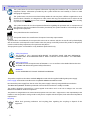
VIDEO SCALING SYSTEM Informatics User manual [ English] © 2012 NDS Surgical Imaging, LLC. All rights reserved. Information in this document has been carefully checked for accuracy; however, no guarantee is given to the correctness of the contents. This document is subject to change without notice. NDSsi provides this information as reference only. Reference to products from other vendors does not imply any recommendation or endorsement. This document contains proprietary information protected by copyright. No part of this manual may be reproduced by any mechanical, electronic, or other means, in any form, without prior written permission of NDSsi. All trademarks are the property of their respective owners. Table of Contents Tab 1 Warnings and Cautions ------------------------------- ii Recycling -------------------------------------------------- ii Declaration of Conformity--------------------------- iii Legal Statement ---------------------------------------- iii Tab 2 About This Manual-------------------------------------- 1 Intended Use and Contraindications -------------- 1 ScaleOR Overview--------------------------------------- 2 General Information------------------------------------ 2 Tab 3 Connector Panel----------------------------------------- 3 Output Mode Switches -------------------------------- 3 Electrical Symbols--------------------------------------- 3 Output Mode Switch Settings ----------------------- 4 Power Supply and Wall Adapters------------------- 5 Removable Input Modules --------------------------- 6 Module Removal and Installation ------------------ 6 Tab 4 System Configuration Example --------------------- 7 Tab 5 Startup ----------------------------------------------------- 8 Tab 6 Control ----------------------------------------------------- 9 Menu Overview ----------------------------------------- 9 ScaleOR Setup ----------------------------------------- 10 DVI and SDI Picture Menu ----------------------- 10 VGA, RGBS, YPbPr, and SOG Menu ------------ 11 Color Menu------------------------------------------- 12 Setup Menu ------------------------------------------ 13 Modes Menu----------------------------------------- 14 Output Modes Table ------------------------------ 15 Restoring Factory Defaults ---------------------- 15 Tab 7 Serial Port Setup and Test-------------------------- 16 Tab 8 Troubleshooting and Test Section --------------- 17 Tab 9 Drawing and Dimensions--------------------------- 18 Tab 10 Connectors and Pin Outs --------------------------- 19 Cable Bend Radius ------------------------------------ 19 Tab 11 Specifications ------------------------------------------ 20 Video Formats------------------------------------------ 21 Video Inputs -------------------------------------------- 21 Cleaning and Disinfecting Instructions --------- 22 Electromagnetic Compatibility (EMC) Tables - 23 Contact------------------------------------------------ Back i 1 Warnings and Cautions This symbol alerts the user that important information regarding the installation and / or operation of this equipment follows. Information preceded by this symbol should be read carefully in order to avoid damaging the equipment. This symbol warns user that un-insulated voltage within the unit may have sufficient magnitude to cause electrical shock. Therefore, it is dangerous to make contact with any part inside the unit. To reduce the risk of electric shock, DO NOT remove cover (or back). There are no user serviceable parts inside. Refer servicing to qualified service personnel. This symbol cautions the user that important information regarding the operation and / or maintenance of this equipment has been included. Information preceded by this symbol should be read carefully to avoid damage to the equipment. This symbol denotes the manufacturer. This symbol denotes the manufacturer’s European Community representative. To prevent fire or shock hazards, do not expose this unit to rain or moisture. Also, do not use this unit's polarized plug with an extension cord receptacle or other outlets unless the prongs can be fully inserted. The product is designed to meet the medical safety requirements for a patient vicinity device. This equipment/system is intended for use by healthcare professionals only. Safety Compliance: This product is T.U.V. approved WITH RESPECT TO ELECTRIC SHOCK, FIRE AND MECHANICAL HAZARDS ONLY IN ACCORDANCE WITH UL 60601-1/CAN/CSA C22.2 NO. 60601-1 and ANSI/AAMI ES60601-1. Safety Compliance: This product meets the requirements of EN-60601-1 so as to conform to the Medical Device Directive 93/42/EEC and 2007/47/EC (general safety information). WARNING: CLASS I LASER PRODUCT. DO NOT STARE INTO LASER BEAM This product complies to the above standards only when used with the supplied medical grade power supply. Power supply: Ault and SL Power Electronic Corp Model: MENB1030A1200C02 12VDC Disconnect the power supply from the AC mains. The power supply is the only recognized disconnect device. The MEDICAL EQUIPMENT should be positioned so that its disconnect device is readily accessible. The product should be powered from a center tapped circuit when used in the US at voltages over 120 volts. Monitor is intended for continuous operation. This product is energized from an external electrical power source for class 1 equipment. It is the responsibility of the installer to test the product’s earth ground to verify that it complies with the hospital, local and national impedance requirements. Recycling: Follow local governing ordinances and recycling plans regarding the recycling or disposal of this equipment . ii Declarations of Conformity FCC and Council Directives of European Standards: This device complies with Part 15 of FCC rules and 93/42/EEC of the Council Directives of European Standards Directive as amended by 2007/47/EC. Operation is subject to the following two conditions: (1) This device may not cause harmful interference, and (2) this device must accept any interference received, including interference that may cause undesirable results. 1. Use the specified cables with this device so as not to interfere with radio and television reception. Use of other cables and / or adapters may cause interference with other electronic equipment. 2. This equipment has been tested and found to comply with the limits pursuant to FCC part 15 and CISPR 11. This equipment generates, uses and can radiate radio frequency energy and, if not installed and used in accordance with the instructions, may cause harmful interference to radio communications. IEC: This equipment has been tested and found to comply with the limits for medical devices to the IEC 60601-1-2. These limits are designed to provide reasonable protection against harmful interference in a typical medical installation. This equipment generates, uses and can radiate radio frequency energy and, if not installed and used in accordance with the instructions, may cause harmful interference to other devices in the vicinity. FCC, Council Directives of European Standards and IEC: There is no guarantee that interference will not occur in a particular installation. If this equipment does cause harmful interference to radio or television reception, which can be determined by turning the equipment off and on, the user is encouraged to try to correct the interference by one or more of the following measures: Reorient or relocate the receiving antenna. Increase the separation between the equipment and receiver. Connect the equipment into an outlet on a circuit different from that to which the receiver is connected. Consult your dealer or an experienced radio/TV technician for help. Accessory equipment connected to this product must be certified according to the respective IEC Standards (i.e., IEC 60950-1) for data processing equipment and IEC 60601-1 for medical equipment). Furthermore, all configurations shall comply with the system standard, IEC 60601-1-1. Anyone who connects additional equipment to the signal input part or signal output part configures a medical system, and is therefore responsible that the system complies with the requirements of system standard IEC 60601-1-1. Whoever is responsible for securing the unit to a system needs to insure that the mounting equipment used with this product complies to IEC standard 60601-1. If in doubt, consult the technical services department or your local representative. Legal Statement NDS sells its products through other medical device manufacturers, distributors and resellers and therefore, purchasers of this NDS product should consult with the entity through which this product was originally purchased regarding the terms of any applicable product warranties provided by such entity, if any. NDS neither assumes nor authorizes any person to assume for it any other liabilities in conjunction with and/or related to the sale and/or use of its products. To ensure proper use, handling and care of NDS products, customers should consult the product specific literature, instruction manual, and/or labeling included with the product or otherwise available. Customers are cautioned that system configuration, software, the application, customer data and operator control of the system, among other factors, affect the product’s performance. While NDS products are considered to be compatible with many systems, specific functional implementation by customers may vary. Therefore, suitability of a product for a specific purpose or application must be determined by the consumer and is not warranted by NDS. NDS SPECIFICALLY DISCLAIMS ALL WARRANTIES OF ANY KIND, WHETHER EXPRESS, IMPLIED AND/OR STATUTORY, INCLUDING, BUT NOT LIMITED TO WARRANTIES OF MERCHANTABILITY, FITNESS AND/OR OF SUITABILITY FOR A PARTICULAR PURPOSE, AND NON-INFRINGEMENT WITH RESPECT TO ALL NDS PRODUCTS OR SERVICES. ANY AND ALL OTHER WARRANTIES, REPRESENTATIONS AND/OR GUARANTEES, OF ANY TYPE, NATURE OR EXTENT, BE IT IMPLIED, EXPRESS AND/OR WHETHER ARISING UNDER OR AS A RESULT OF ANY STATUTE, LAW, COMMERCIAL USAGE, CUSTOM, TRADE OR OTHERWISE, ARE HEREBY EXPRESSLY EXCLUDED AND DISCLAIMED. NDS, its suppliers and/or distributors are not liable, directly or by way of indemnity for any special, incidental, consequential, punitive, exemplary or indirect damages, including but not limited to alleged damages for delayed shipment, non-delivery, product failure, product design or production, inability to use such products or services, loss of future business (lost profits), or from any other cause, whatsoever, in connection with or arising from the purchase, sale, lease, rental, installation or use of such NDS products, these terms and conditions, or with respect to any the terms of any agreement which incorporates these terms and conditions. SOME JURISDICTIONS DO NOT ALLOW EXCLUSIONS AND DISCLAIMERS OF CERTAIN WARRANTIES OR LIMITATIONS OF LIABILITY, SO THE LIMITATIONS AND/OR EXCLUSIONS, SET FORTH HEREIN, MAY NOT APPLY. IN THAT EVENT LIABILITY WILL BE LIMITED TO THE GREATEST EXTENT PERMITTED BY LAW IN THE SUBJECT JURISDICTION. The information provided in this document, including all designs and related materials, is the valuable property of NDS and / or its licensors and, as appropriate, they reserve all patent, copyright, and other proprietary rights to this document, including all design, manufacturing reproduction, use, and sales rights thereto, except to the extent said rights are expressly granted to others. iii About This Manual 2 This manual is designed to assist the user with installation, setup and operation of the ScaleOR and its associated displays. A list of displays that may be used with the ScaleOR is in the Compatible Displays section under General Information on the following page. A numbered tab on the side of the page denotes the beginning of a section. The functional descriptions in this manual are representative of: Part Numbers: The part numbers are shown in table below Firmware: 58J0079 Rev A. This version supports only the DVI and 3G-SDI input modules. 58J0079 Rev B. This version adds support for the VGA input module. 58J0079 Rev C. This version adds support for the S-Video / Composite input module. 58J0079 Rev D. Added Alternative Mode Tolerance and Auto Select on the S-Video / Composite module. Manual Part Number 60G0453 Rev D Part Number Input Module Fiber Optic Output? 90T0009 DVI No 90T0010 DVI Single Fiber 90T0011 SDI No 90T0012 SDI Single Fiber 90T0013 VGA No 90T0014 VGA Single Fiber 90T0015 S-Video / Composite No 90T0016 S-Video / Composite Single Fiber Intended Use and Contraindications Intended Use: This device is intended for use in a medical environment to deliver high quality video and graphic images. Contraindications: This device may not be used in the presence of flammable anesthetics mixture with air, oxygen or nitrous oxide. Also, it is not intended for life support applications. No part of this product may come in contact with a patient. Never touch the product and a patient at the same time. Warning: Because invisible laser radiation may be emitted from the aperture of the port when no fiber cable is connected, avoid exposure to laser radiation and do not stare into open apertures. For mission critical applications, we strongly recommend that a replacement unit be immediately available. 1 ScaleOR Overview The ScaleOR accepts 1 of following 4 input modules: DVI-D SDI VGA S-Video / Composite The drawing on page 3 shows location of the fixed output connectors and the input module. The output mode (resolution) may be selected using the DIP switches located on the bottom of the ScaleOR (see Output Mode Switch Settings table on page 4). General Information Installation: ScaleOR units may be stacked on a equipment carrier, a surgical cart or mounted in a standard 19” rack. Ensure that the air vents are not blocked. Power Supply: The provided power supply, Ault and SL Power Electronic Corp Model: MENB1030A1200C02 12VDC, includes 4 interchangeable wall plug adapters. Drawings of the power supply, its adapters, and adapter installation information are on page 5. Compatible Displays: 1. HD displays with a DVI input. 2. HD displays with HD-SDI or 3G-SDI input. 3. HD displays with Fiber Optic input. Note: The ScaleOR’s Fiber Optic output is an optional feature. Control Options: The ScaleOR may be controlled from: 1. The keypad on the front of the ScaleOR. Using the keypad requires that the ScaleOR be connected to a display. 2. A PC via the ND-OS port. See Serial Port Setup and Test on page 16. The NDS Unified Serial Commands (P/N 60A0156) document contains a complete set of serial commands for the ScaleOR. Please contact your NDS sales representative for details. 2 Connector Panel 3 Notes: Power input, use the provided 12VDC power supply only. Optional Fiber Optic output Input module, DVI-D module shown, all input modules are shown on page 6. The ND-OS connector allows the ScaleOR to be controlled remotely via serial commands. It is also used to install BIOS upgrades. SDI and DVI video outputs. Output Mode Switches The Output Mode Switches, accessible on the underside of the unit, allow the user to select 1 of 46 output modes. The Output Mode Switch Settings table on the following page shows the switch settings required to select a given output mode. Setting the output mode from the On Screen Menu (OSM) requires that all switches be set to off. Electrical Symbols Power Switch: The Power Switch symbol is shown to the left. The power switch is push on / push off and is shown below the Power Switch symbol. When the switch is off the ring around the center portion is white. When the switch is on, the center portion is depressed and the ring is illuminated blue. The illustration shows the switch in its ON state. When the ScaleOR is turned on the blue ring flashes at the rate of 5 flashes per second for 15 seconds then, becomes steady if a video signal is detected. If a video signal is not detected the ring continues flashing at the rate of 1 flash per second. 3 Output Mode Switch Settings Legend: F = Off, O = On Mode Index 0 1 2 3 4 5 6 7 8 9 10 11 12 13 14 15 16 17 18 19 20 21 22 23 24 25 26 27 28 29 30 31 32 33 34 35 36 37 38 39 40 41 42 43 44 45 46 47 DVI Mode 720x487/59.94P 720x576/50.00P 1280X720/23.98P 1280X720/24.00P 1280X720/25.00P 1280X720/29.97P 1280X720/30.00P 1280x720/50.00P 1280x720/59.94P 1280x720/60.00P 1920x1080/50.00P 1920x1080/59.94P 1920x1080/60.00P 1920x1080/23.98P 1920x1080/24.00P 1920x1080/25.00P 1920x1080/29.97P 1920x1080/30.00P 1920x1080/50.00P 1920x1080/59.94P 1920x1080/60.00P 640x480/60 VGA 640x480/75 VGA 640x480/85.01 VGA 800x600/60.32 SVGA 800x600/75 SVGA 800x600/85.06 SVGA 1024x768/60 XGA 1024x768/75.03 XGA 1024x768/85 XGA 1152x864/70.01 XGA 1152x864/75 XGA 1152x864/85 XGA 1280x768/59.87 WXGA 1280x960/60 SXGA 1280x960/75 SXGA 1280x960/85 SXGA 1280x1024/60.02 SXGA 1280x1024/75.02 SXGA 1280x1024/85.02 SXGA 1360X768/60.01WXGA 1366X768/59.79 WXGA 1440X900/59.89 WXGA 1600X1200/60 UXGA 1680X1050/59.95 WSXGA 1920x1200/50 WUXGA 1920x1200/60 WUXGA Use Menu SDI Mode 720x480/59.94I 720x576/50.00I 1280X720/23.98P 1280X720/24.00P 1280X720/25.00P 1280X720/29.97P 1280X720/30.00P 1280x720/50.00P 1280x720/59.94P 1280x720/60.00P 1920x1080/50.00I 1920x1080/59.94I 1920x1080/60.00I 1920x1080/23.98P 1920x1080/24.00P 1920x1080/25.00P 1920x1080/29.97P 1920x1080/30.00P 1920x1080/50.00P 1920x1080/59.94P 1920x1080/60.00P N/A N/A N/A N/A N/A N/A N/A N/A N/A N/A N/A N/A N/A N/A N/A N/A N/A N/A N/A N/A N/A N/A N/A N/A N/A N/A * DIP Switch 6 5 4 3 2 1 O O O O O O O O O O O O O O O O O O O O O O O O O O O O O O O O F F F F F F F F F F F F F F F F O O O O O O O O O O O O O O O O F F F F F F F F F F F F F F F F O O O O O O O O O O O O O O O F O O O O O O O O F F F F F F F F O O O O O O O O F F F F F F F F O O O O O O O O F F F F F F F F O O O O F F F F O O O O F F F F O O O O F F F F O O O O F F F F O O O O F F F F O O O O F F F F O O F F O O F F O O F F O O F F O O F F O O F F O O F F O O F F O O F F O O F F O O F F O O F F O F O F O F O F O F O F O F O F O F O F O F O F O F O F O F O F O F O F O F O F O F O F O F O F * Note: To set the output mode from the ScaleOR’s OSM, all switches must be set to Off . 4 Power Supply and Wall Adapters The power supply is shown with the US wall adapter installed. To exchange the adapter, proceed as follows: Place the power supply on your work surface as shown. Press and hold the button labeled PUSH. Twist the adapter 1/8 turn toward the OPEN arrow, and lift it off the power supply. Select one of the provided wall adapters. Align the tabs on the bottom of the adapter with the notches on the power supply and place the adapter on the power supply. Press the adapter down and twist it toward the LOCK arrow until it clicks into place. 5 Removable Input Modules Input Modules: Four types of input modules are available: DVI-D, 3G-SDI, VGA and S-Video / Composite The DVI-D input module accepts DVI signals up to 1920 x 1200 progressive at 60Hz. The 3G-SDI input module accepts SDI signals up to 1920 x 1080 progressive at 60Hz. The VGA input module accepts analog signals up to 1920 x 1200 progressive at 60Hz. The S-Video / Composite input module accepts S-Video / Composite NTSC or PAL signals . Any one of the input modules shown below may be installed in the card slot. DVI-D 3G-SDI VGA Function RGBS YPbPr VGA SOG OSM / RS-232 VGA Module Switches Switch 1 Switch 2 On On Off On On Off Off Off Off Off S-Video / Composite Switch 3 Off Off Off Off On 1. To select the Input Format using the OSM or via Serial control switch 3 must be On. When switch 3 is On switches 1 and 2 are disabled. 2. To select the input format manually turn switch 3 Off. Then, using the table to the left, set switches 1 and 2 to the format of the input signal. Module Removal and Installation The ScaleOR must be turned off prior to installing or replacing the input module. Input Module Removal: Use a number 1 Phillips screwdriver to loosen, but not remove, the screws located on the left and right sides of the module’s mounting plate. When the screws are clear of the chassis, remove the module by gripping the screws and pulling the module out. Installation: Slide the new module into the chassis until it contacts the connector, then push gently until the module seats. The module is correctly seated when its mounting plate is flush with the chassis’s back panel. Thread the module’s screws into the chassis until they touch the mounting plate, then tighten each screw by turning it another quarter turn. 6 System Configuration Example 4 ▲ ▲ DVI Out ◄ Optional PC control 7 SDI Out ► ▲ SDI, DVI, VGA, or S-Video / Composite Source Startup Connect one of the ScaleOR’s outputs to a compatible monitor. Connect a video source to the ScaleOR’s input. Press the power button the ScaleOR’s front panel. The power button’s illuminated blue ring flashes for 15 seconds then, if a video signal is detected, becomes steady. If a video signal is not detected the ring continues flashing. The NDS logo is displayed on the monitor until the ScaleOR’s initialization is complete. At which time the illuminated ring stops flashing, if a video signal is detected, and becomes steady blue. At this time an image of the video signal connected to the ScaleOR’s input is displayed on the monitor. If the ScaleOR has been turned on for more than 15 seconds and a video signal is not detected the blue ring is will flash at the rate of 1 flash per second. 5 ScaleOR 8 Control A 4 button keypad, located below and to the right of the ScaleOR logo, allows the user to make adjustments to various ScaleOR parameters using the On Screen Menu (OSM) system. 6 Menu System Overview Press the MENU button once to open the OSM. The input and output resolution are shown at the top of the menu. The Picture menu is displayed when the OSM is opened. Press the fi or fl button to select the menu you want to work with, then press the SCROLL button to select the parameter. Press the fi or fl button to set the parameter to the desired value. Press the MENU button to save your changes and close the OSM. Notes: 1. Grayed out parameters are not currently accessible. 9 ScaleOR Setup DVI and SDI Picture Menu Sharpness: Press fi or fl to adjust the sharpness (focus) of the displayed image. Scaling (Graphics): This parameter is enabled when the input signal is not 16:9, not interlaced, and not 480P or 576P. Fill = Expands the video image to fill the entire screen. The aspect ratio may not be accurately displayed. Aspect = Expands the video image until its largest dimension fills the screen. Image may be displayed with black bars on the top and bottom or the left and right. 1:1 = Displays the video data in its native size and aspect ratio. Image may be displayed with black bars on the top and bottom and on the left and right. Select using fi or fl buttons. Zoom (Video): This parameter is enabled when the input is 16:9, 480P, 576P, or interlaced. 0 = The image is displayed at a size that fills the screen without losing any video information. The image presented to the display may include black bars top and bottom or left and right. 1, 2, 3, 4, 5 or 6 = The image is linearly enlarged, while remaining centered, in incremental steps. As the image becomes larger video information will be lost from the top and bottom and / or left and right. Select using fi or fl buttons. 10 VGA, RGBS, YPbPr, and SOG Picture Menu Horizontal Position: Moves the image to the left or right. Press fi or fl to horizontally center the image. Vertical Position: Moves the image up or down. Press fi or fl to vertically center the image. Sharpness: Press fi or fl to adjust the sharpness (focus) of the displayed image. Phase: Press fi or fl to adjust the phase of the display’s pixel clock. Frequency: Adjusts the frequency of the display’s pixel clock. With Scaling set to Fill adjust until image just fills the screen horizontally. Press fi or fl to adjust the frequency of the display’s pixel clock. Scaling (Graphics): This parameter is enabled when the input signal is not 16:9, not interlaced, and not 480P or 576P. Fill = Expands the video image to fill the entire screen. The aspect ratio may not be accurately displayed. Aspect = Expands the video image until its largest dimension fills the screen. Image may be displayed with black bars on the top and bottom or the left and right. 1:1 = Displays the video data in its native size and aspect ratio. Image may be displayed with black bars on the top and bottom and on the left and right. Select using fi or fl buttons. Zoom (Video): This parameter is enabled when the input is 16:9, 480P, 576P, or interlaced. 0 = The image is displayed at a size that fills the screen without losing any video information. The image presented to the display may include black bars top and bottom or left and right. 1, 2, 3, 4, 5 or 6 = The image is linearly enlarged, while remaining centered, in incremental steps. As the image becomes larger video information will be lost from the top and bottom and / or left and right. Select using fi or fl buttons. SmartSync™ / Alternative Modes On initialization NDS’ proprietary SmartSync technology examines the incoming signal and automatically displays the video image in its proper format. To run SmartSync highlight the SmartSync / Alternative Modes parameter and press the fi button. To select an alternate mode (format) highlight the SmartSync / Alternative Modes parameter and press the fl button. The mode increments each time the fl button is pressed until the selected mode equals the maximum available, the next time fl pressed the first mode is restored. Alternative Modes are used to manually distinguish between modes (resolutions) whose timing characteristics are very close. 11 Color Menu Brightness: Press the fi or fl button to adjust brightness. Contrast: Press the fi or fl button to adjust contrast. Red, Green, Blue: Press the fi or fl button to increase or decrease the intensity of the selected color. Saturation (Video): This parameter is enabled only when the input is 16:9, 480P, 576P, or interlaced. Press fi or fl to set the saturation (color intensity) of the image. Hue (Video): This parameter is enabled only when the input is 16:9, 480P, 576P, or interlaced. Press fi or fl to set the hue (color tint) of the image. 12 Setup Menu Input Format: Press the fi or fl button to match the format of the input signal. Notes: 1. This parameter is not available when a DVI or 3G - SDI input module is installed in the ScaleOR. 2. If this parameter is “grayed” out when the VGA module is installed, then the VGA module has been preconfigured to accept only the format that appears in blue. To select a different Input Format, or configure the VGA module to allow the Input Format to be selected from the OSM or via an RS-232 serial command consult the VGA Module Switches table on page 6. 3. When the S-Video / Composite module is installed, there are three Input Format parameter options: Auto*, S-Video, or Composite. When Auto is selected the ScaleOR switches between the S-Video and Composite inputs until a signal is detected. Each input is scanned for approximately five seconds after which the ScaleOR switches to the other input. When S-Video is selected, only the S-Video input is scanned. The same is true the Composite input is selected. *The Auto option is available with BIOS 58J0079 Rev D and later. Alternative Mode Tolerance: This parameter allows the user compensate for input signals whose timing parameters may differ from those stored in the ScaleOR. Press the fi or fl button to select one of the tolerance parameters. The Alternative Mode Tolerance options are available with BIOS 58J0079 Rev D and later. Menu Position: Places the menu in 1 of 9 predefined screen positions. Press the fi or fl button to select any of the 9 screen positions. Language: English only. DPMS Enable: Display Power Management System. When DPMS is enabled (on), and no input signal is present, or the signal is removed, then, if the unit is connected to a monitor, the “ScaleOR D.P.M.S” message is displayed for 10 - 15 seconds. After which the ScaleOR goes into standby mode, and turns its outputs off. When an input signal is applied the ScaleOR comes out of standby and turns its outputs on. Press the fl button to enable DPMS, press the fi button to disable DPMS. Menu Lock: Disables access to menu system. This prevents inadvertent changes to the ScaleOR’s settings. To enable Menu Lock, press the fl button. MENU LOCKED is displayed when the fi button is pressed. To unlock, simultaneously press and hold the MENU and SCROLL buttons until MENU UNLOCKED is displayed. Operating Hours: Shows the ScaleOR’s hours of operation. BIOS: Installed version of the ScaleOR’s BIOS firmware. 13 Modes Menu The available output modes are shown when the Modes tab is selected. If the Modes tab is selected using the fl button, the tab’s legend changes to Modes 0-15 and modes 0 through 15 are displayed. Pressing the fl button a second time, changes the tab’s legend to Modes 16-31 and modes 16 through 31 are displayed. If the fl button is pressed a third time the tab’s legend changes to Modes 32-47, modes 32 through 46 are displayed. Mode 47 is not implemented and is shown as None. Finally, pressing the fl button a fourth time selects the Picture menu. When the fi button is used to select the Modes tab, the sequence described above occurs in reverse order. All available output modes are shown in the table on the following page. Press the fl button to select the group of modes (0-15, 16-31 or 32-47) that contains the output mode that you want to use. Press the SCROLL button to highlight the pair of modes that contains the mode to be used. This message appears on the bottom of the OSM. Press the fi or fl button to select the new output mode. The following message appears on bottom of the OSM. Press this button to confirm the new output mode. The following message is shown on the bottom of the OSM. If the MENU button is not pressed within 20 seconds the output mode reverts to the previous output mode. Press this button to cancel the new output mode. The following message is shown on the bottom of the OSM. If the Modes menu appears as shown below, then one or more of the mode switches is turned on, and the Modes menu is locked. To use the Modes menu turn all of the mode switches off. See page 3 for the Output Mode Switches location. Note: When the Modes menu is selected, the currently active mode is shown in blue, even if the menu is locked. 14 Output Modes Table Mode Index Input: Mode Mode Index Input: Mode Mode Index Input: Mode 0000 DVI/SDI 720x487p/i@59Hz 0016 DVI/SDI 1920x1080p@29Hz 0032 DVI Only 1152x864@85Hz 0001 DVI/SDI 720x576p/i@50Hz 0017 DVI/SDI 1920x1080p@30Hz 0033 DVI Only 1280x768@59Hz 0002 DVI/SDI 1280x720p@23Hz 0018 DVI/SDI 1920x1080p@50Hz 0034 DVI Only 1280x960@60Hz 0003 DVI/SDI 1280x720p@24Hz 0019 DVI/SDI 1920x1080p@59Hz 0035 DVI Only 1280x960@75Hz 0004 DVI/SDI 1280x720p@25Hz 0020 DVI/SDI 1920x1080p@60Hz 0036 DVI Only 1280x960@85Hz 0005 DVI/SDI 1280x720p@29Hz 0021 DVI Only 640x480@60Hz 0037 DVI Only 1280x1024@60Hz 0006 DVI/SDI 1280x720p@30Hz 0022 DVI Only 640x480@75Hz 0038 DVI Only 1280x1024@75Hz 0007 DVI/SDI 1280x720p@50Hz 0023 DVI Only 640x480@85Hz 0039 DVI Only 1280x1024@85Hz 0008 DVI/SDI 1280x720p@59Hz 0024 DVI Only 800x600@60Hz 0040 DVI Only 1360x768@60Hz 0009 DVI/SDI 1280x720p@60Hz 0025 DVI Only 800x600@75Hz 0041 DVI Only 1366x768@59Hz 0010 DVI/SDI 1920x1080p/i@50Hz 0026 DVI Only 800x600@85Hz 0042 DVI Only 1440x900@59Hz 0011 DVI/SDI 1920x1080p/i@59Hz 0027 DVI Only 1024x768@60Hz 0043 DVI Only 1600x1200@60Hz 0012 DVI/SDI 1920x1080p/i@60Hz 0028 DVI Only 1024x768@75Hz 0044 DVI Only 1680x1050@59Hz 0013 DVI/SDI 1920x1080p@23Hz 0029 DVI Only 1024x768@85Hz 0045 DVI Only 1920x1200@50Hz 0014 DVI/SDI 1920x1080p@24Hz 0030 DVI Only 1152x864@70Hz 0046 DVI Only 1920x1200@60Hz 0015 DVI/SDI 1920x1080p@25Hz 0031 DVI Only 1152x864@75Hz 0047 N/A None *Note: If a Mode contains “p/I” then the ”p” (progressive scan) applies to the DVI output signal and the ”i” (interlaced scan) applies to the SDI output signal. Modes that contain only a “p” are progressive whether the output is DVI or SDI. The DVI Only modes are always progressive and only the DVI port will have an output signal. Restoring Factory Defaults To restore the Factory Defaults turn the ScaleOR off, press and hold the MENU button. While holding the MENU button, turn the unit on. After approximately 10 seconds the “Restoring Factory Defaults” message appears on the monitor connected to the ScaleOR. 15 Serial Port Setup and Test Hardware Setup Turn the ScaleOR on. Connect your PC to the ScaleOR using a USB to Mini 5 USB (NDS P/N 35Z0047) or equivalent cable. Device Manager Open the PC’s Device Manager, and select Ports (COM & LPT). Find the USB Serial Port (COMx) entry. Use the port number in the ( ) when you setup Hyper Terminal. Hyper Terminal Setup The table below shows the serial port parameters. Click Start Select All Programs > Accessories > Communications Click Hyper Terminal Enter a name for the new connection and click OK. In the Connect To menu, select the COM port number that matches the USB Serial Port you found using the Device Manager from the Connect Using drop down menu and click OK. In the COM Properties menu: Parameter Setting Set Bits per second to 19200 Baud Rate 19200 Set Data bits to 8 Parity None Set Parity to None Data Bits 8 Set Stop bits to 1 Stop Bits 1 Set Flow control to None Flow Control None Click OK Click File, click Properties, then select ASCII Setup from the Properties menu In the ASCII Setup menu select: Echo typed characters locally. Click OK to exit ASCII Setup Click OK to exit configuration. Click File and select Save to save the configuration. 7 Serial Port Test Place the cursor in the text area of the Hyper Terminal window and press Enter, !0003C3 is displayed. Type :0000000080 and press Enter. !000058J0079RBBxx is displayed. Where: ! = Start of response. 0000 = Response OK. 58J = BIOS type. 0079 = BIOS number. R = Revision letter. BB = Build number (minor revision). xx = Checksum A complete set of ScaleOR serial commands is available. See the General Information section on page 2. 16 Troubleshooting and Test Section Problem Possible Causes and Remedies Power switch does not Loose power cable: Verify that the power cable is fully inserted into the unit’s illuminate in the ON power connector and that the power supply’s connector collar is properly state threaded onto the ScaleOR’s power connector. Defective power supply: Replace the power supply. Wall socket: Some wall sockets have on / off switches built in. If the socket you are using has a built in switch, verify that is in the on position. Mitigation: Bypass the ScaleOR by connecting the output of the video source directly to a monitor. Confidence test Turn the ScaleOR off, then connect its DVI output port to a powered up monitor. Turn the ScaleOR on, the NDS logo should appear on the monitor approximately 10 seconds after the ScaleOR is turned on. Turn the ScaleOR off, then connect its SDI output port to the monitor and repeat the test. If your ScaleOR has a Fiber Optic output, turn the ScaleOR off, then connect its fiber Optic output port to the monitor and repeat the test. Video is not displayed If the ScaleOR’s power button’s blue ring is flashing once per second, then the unit is not detecting a video signal. Verify that an input signal is connected to the unit’s input. If there is a connection try replacing the video cable. If video appears, then the cable is bad. If video does not appear, then connect the unit to a different video source. If video appears, then the previous video source is turned off, or defective. If video still does not appear, then the ScaleOR’s Input module may be defective, or not properly seated. Try reseating the input module. If that doesn’t clear the problem then the input module is defective. 8 If you determine that the input module is defective, please contact customer service for assistance. Mitigation: If possible, connect the video source directly to the video source. Video is not displayed Verify that video is displayed from the DVI or SDI output port. If video from the from a given output port DVI port is displayed, and not from the SDI port then ScaleOR’s output mode may set to a DVI only mode (see Output Modes Table on page 15), the cable connecting the SDI port to a monitor may be bad or the SDI output is defective. If video from the SDI port is displayed, and not from the DVI port then the cable from the DVI port may be bad, or the DVI port is defective. If you determine that one of the output ports is defective, please contact customer service for assistance. External control failure USB cable is loose or defective: Verify that the USB cable is fully inserted into the ScaleOR’s USB port and the PC’s USB port. Control program has failed: Restart the program Controlling PC has failed: Restart the PC Mitigation: Control the ScaleOR from its front panel Keypad 17 Drawing and Dimensions 9 18 Connectors and Pin Outs Input Connectors DVI Input and Output Connectors DVI-D* Digital only. VGA 1 RED 6 GND RED 11 N. C. 2 GREEN 7 GND GREEN 12 DDC_SDA 3 BLUE 8 GND BLUE 13 HORIZ SYNC 4 N.C. 9 +5VDC 14 VERT SYNC. 5 GND 10 SYNC GND 15 DDC_SCL S-Video Pin Name Description * Compliant with DVI 1.0 PIN# SIGNAL PIN# SIGNAL 1 T.M.D.S. DATA 2- 16 HOT PLUG DETECT 2 T.M.D.S. DATA 2+ 17 T.M.D.S. DATA 0- 3 T.M.D.S. DATA 2/4 SHIELD 18 T.M.D.S. DATA 0+ 4 T.M.D.S. DATA 4- 19 T.M.D.S. DATA 0/5 SHIELD 5 T.M.D.S. DATA 4+ 20 T.M.D.S. DATA 5- 1 GND Ground (Y) 2 GND Ground (C) 6 DDC CLOCK 21 T.M.D.S. DATA 5+ 3 Y Intensity (Luminance) 7 DDC DATA 22 4 C Color (Chrominance) T.M.D.S. CLOCK SHIELD 23 T.M.D.S. CLOCK+ 24 T.M.D.S. CLOCK- 8 10 Data Connector USB Connector Pin 9 T.M.D.S. DATA 1- 10 T.M.D.S. DATA 1+ 11 T.M.D.S. DATA 1/3 SHIELD 12 T.M.D.S. DATA 3- 13 T.M.D.S. DATA 3+ 14 +5V POWER 15 GND Name Description 1 VCC +5 VDC 2 D- Data - 3 D+ Data + X ID N/C Pin Name Description 4 GND Ground Input Input Serial Video Data Output Connector Fiber Optic Cable Bend Radius We recommend that the bend radius of metallic cables be no less than 2.5 inches (63 mm) or 7 times the diameter of the cable whichever is greater. The bend radius of Fiber Optic cables should be no less than 10 times the diameter of the cable. Sharper bends may damage the cable and / or degrade the video signal. 19 Specifications1 DVI and Fiber Output Resolution User selectable. See Output Modes Table on page 15 SDI Output Resolution User selectable. See Output Modes Table on page 15 HD-SDI Input signal level .8 to 2.0 V p-p DC Power Consumption 22W AC Power Consumption 30W System Weight 1.3lbs (0.59 kg) Environmental Operating Temperature +32 to 950F (0 to 350C) Operating Humidity 20 to 85% RH Operating Altitude 6562 ft (2,000 m) Storage Temperature -4 to +1220F (-20 to +500C) Storage Humidity 5 to 85% RH Storage Altitude 32808 ft (10,000 m) Notes: 1. Specifications are subject to change without notice. Contact NDS for recent specifications. 11 20 DVI Supported Resolutions Signal Parameter Active Resolution (Horizontal x Vertical Supported Range 640 x 480 min to 1920 x 1200 max Refresh Rate (Vertical Frequency) 23.98 Hz up to 85 HZ Pixel Clock 25 MHz up to 165 MHz (Pixel Frequency) The DVI-D input can automatically detect any valid digital DVI signal within the resolution, vertical refresh, and pixel clock ranges specified in the table above. Signals outside of any of the specified ranges may not be supported. Horizontal Resolution (pixels) 720 720 720 720 640 640 640 640 640 640 640 640 640 640 640 640 720 720 800 800 800 800 800 800 Vertical Resolution (lines) 480i 480p 576i 576p 350 350 350 400 400 480 480 480 480 480 480 480 400 400 600 600 600 600 600 600 Vertical Frequency (Hz) 29.97 59.94 25 50 50 60 70 50 70 50 60 67 70 72.81 75 85.01 70 85.04 56.25 60.32 60.38 72.19 75 85.06 Horizontal Resolution (pixels) 720 720 720 720 720 1280 1280 1280 SDI Supported Resolutions Vertical Horizontal Vertical Frequency Resolution Resolution (Hz) (pixels) (lines) 29.97 1280 720p 29.97 1280 720p 29.97 1920 1080sF 25 1920 1080p 25 1920 1080p 24 1920 1080p 25 1920 1080i 30 1920 1080i VGA, RGBS, and YPbPr Supported Resolutions Horizontal Vertical Vertical Horizontal Resolution Resolution Frequency Resolution (pixels) (lines) (Hz) (pixels) 1024 768i 43.48 1280 1024 768 50 1280 1024 768 59.94 1280 1024 768 60 1280 1024 768 64 1280 1024 768 70.07 1280 1024 768 75.03 1280 1024 768 84.99 1294 1152 576 50 1440 1152 864 60.05 1600 1152 864 70.01 1600 1152 864 75 1920 1152 864 85 1920 1152 900 66 1920 1280 720p 24 1920 1280 720p 25 1920 1280 720p 30 1920 1280 720p 50 1920 1280 720p 59.94 1920 1280 960i 29.97 1920 1280 960 59.94 1920 1280 960 60 1280 960 75 1280 960 85 Inputs Connector Type DVI DVI-D 3G-SDI BNC, 75 Ohm terminated VGA / RGBS / YPbPr / SOG HD-15 S-video DIN-4 Composite BNC, 75 Ohm terminated Outputs Connector Type DVI DVI-D SDI BNC Fiber LC 21 Vertical Resolution (lines) 480i 483i 487i 576i 587i 720p 720p 720p Vertical Resolution (lines) 1024i 1024 1024 1024 1024 480p 576p 960 900 1200i 1200 1080sF 1080p 1080p 1080p 1080i 1080i 1080p 1080p 1200 1200 Vertical Frequency (Hz) 50 59.94 24 24 25 29.97 25 29.97 Vertical Frequency (Hz) 43.44 60 60.02 75.02 85.02 59.94 50 59.96 59.94 48.04 60 24 24 25 29.97 25 29.97 50 59.94 30 50 Cleaning and Disinfecting Instructions Prior to cleaning and surface disinfection, the unit should be turned OFF and disconnected from its power source. Cleaning: Thoroughly wipe all exterior surfaces with a lint-free cloth that has been dampened with an acceptable cleaning agent. Acceptable cleaning materials are listed below. Remove residual detergent by wiping all exterior surfaces with a lint-free cloth dampened with distilled water. Disinfecting: Disinfect the unit by wiping all exterior surfaces with a lint-free cloth dampened with 80% Ethyl Alcohol. Allow the unit to air dry. Cautions: Do not allow liquids to enter the interior of the unit, and do not permit exterior surfaces to come into contact will unacceptable solvents such as those listed below, as severe damage to the unit may result. Acceptable Cleaning Materials: Vinegar (distilled white vinegar, 5% acidity) Ammonia-based glass cleaner Acceptable Disinfecting Material: Ethanol 80 % by volume Unacceptable solvents: MEK (Methyl Ethyl Ketone) Toluene Acetone Note: The acceptable cleaning and disinfecting materials listed above have been tested on NDS products and, when used as directed, do not harm the product’s finish and or its plastic components. 22 Electromagnetic Compatibility (EMC) Tables All medical electronic devices must conform to the requirements of IEC 60601-1-2. Precautions, adherences to the EMC guideline information provided in this manual and verification of all medical devices in simultaneous operation are required to ensure the electromagnetic compatibility and coexistence of all other medical devices prior to a surgical procedure. The EMC tables on next three pages are provided for your reference. 23 EMC Tables Guidance and manufacturer’s declaration – electromagnetic emissions The product is intended for use in the electromagnetic environment specified below. The customer or the user of the product should assure that it is used in such an environment. Emissions Compliance RF emissions CISPR 11 Group 1 RF emissions CISPR 11 Class A Harmonic emissions IEC 61000-3-2 Not Applicable Voltage fluctuations/ flicker emissions IEC 61000 -3-3 Electromagnetic environment-- guidance The product uses RF energy only for its internal function. Therefore, its RF emissions are very low and are not likely to cause any interference in nearby electronic equipment. The product is suitable for use in all establishments, including domestic establishments and those directly connected to the public low-voltage power supply network that supplies buildings used for domestic purposes. Not Applicable Guidance and manufacturer’s declaration 211; electromagnetic immunity The product is intended for use in the electromagnetic environment specified below. The customer or the user of the product should assure that it is used in such an environment. Immunity test IEC 60601 test level Compliance level Electromagnetic environment guidance Electrostatic discharge (ESD) IEC 61000-4-2 ±6 kV contact ±8 kV air ±6 kV contact ±8 kV air Floors should be wood, concrete or ceramic tile. If floors are covered with synthetic material, the relative humidity should be at least 30 %. Electrical fast transient/burst IEC 61000-4-4 ±2 kV for power supply lines ±2 kV for power supply lines Mains power quality should be that of a typical commercial or hospital environment. Surge IEC 61000-4-5 ±1 kV line(s) and neutral ±1 kV line(s) and neutral Mains power quality should be that of a typical commercial or hospital environment. Voltage dips, short interruptions and voltage variations on power supply input lines IEC 61000-4-11 <5 % UT (>95 % dip in UT) for 0,5 cycle 40 % UT (60 % dip in UT) for 5 cycles 70 % UT (30 % dip in UT) for 25 cycles <5 % UT (>95 % dip in UT) for 5s 3 A/m <5 % UT (>95 % dip in UT) for 0,5 cycle 40 % UT (60 % dip in UT) for 5 cycles 70 % UT (30 % dip in UT) for 25 cycles) <5 % UT (>95 % dip in UT) for 5s Mains power quality should be that of a typical commercial or hospital environment. If a dips or an interruption of mains power occurs, the current of the product may be dropped off from normal level, it may be necessary to use uninterruptible power supply or a battery. Not applicable Not applicable Power frequency (50/60 Hz) magnetic field IEC 61000-4-8 NOTE UT is the a.c. mains voltage prior to application of the test level 24 EMC Tables Guidance and manufacturer’s declaration – electromagnetic immunity The product is intended for use in the electromagnetic environment specified below. The customer or the user of the product should assure that it is used in such an environment. Immunity test IEC 60601 test level Compliance level Conducted RF IEC 61000-4-6 3 Vrms 150 kHz to 80 MHz 3 Vrms Radiated RF IEC 61000-4-3 3 V/m 80 MHz to 2.5 GHz Electromagnetic environment – guidance Portable and mobile RF communications equipment should be used no closer to any part of the product, including cables, than the recommended separation distance calculated from the equation applicable to the frequency of the transmitter. Recommended separation distance 3 V/m where P is the maximum output power rating of the transmitter in watts (W) according to the transmitter manufacturer and d is the recommended separation Distance in metres (m). Field strengths from fixed RF transmitters, as determined by an electromagnetic site survey,a should be less than the compliance level in each frequency range.b Interference may occur in the vicinity of equipment marked with the following symbol: NOTE 1 At 80 MHz and 800 MHz, the higher frequency range applies. NOTE 2 These guidelines may not apply in all situations. Electromagnetic propagation is affected by absorption and reflection from structures, objects and people. a. Field strengths from fixed transmitters, such as base stations for radio (cellular/cordless) telephones and land mobile radios, amateur radio, AM and FM radio broadcast and TV broadcast cannot be predicted theoretically with accuracy. To assess the electromagnetic environment due to fixed RF transmitters, an electromagnetic site survey should be considered. If the measured field strength in the location in which the product is used exceeds the applicable RF compliance level above, the product should be observed to verify normal operation. If abnormal performance is observed, additional measures may be necessary, such as re-orienting or relocating the product. b. Over the frequency range 150 kHz to 80 MHz, field strengths should be less than 3 V/m. 25 EMC Tables Recommended separation distances between portable and mobile RF communications equipment and the product The product is intended for use in an electromagnetic environment in which radiated RF disturbances are controlled. The customer or the user of the product can help prevent electromagnetic interference by maintaining a minimum distance between portable and mobile RF communications equipment (transmitters) and the product as recommended below, according to the maximum output power of the communications equipment. Rated maximum output power (W) of transmitter Separation distance, in meters according to frequency of transmitter 150 kHz to 80 MHz 80 MHz to 800 MHz 800 MHz to 2.5 GHz 0.01 0.12 0.12 0.23 0.1 0.38 0.38 0.73 1 1.2 1.2 2.3 10 3.8 3.8 7.3 100 12 12 23 For transmitters rated at a maximum output power not listed above, the recommended separation distance d in meters (m) can be estimated using the equation applicable to the frequency of the transmitter, where P is the maximum output power rating of the transmitter in watts (W) according to the transmitter manufacturer. NOTE 1 At 80 MHz and 800 MHz, the separation distance for the higher frequency range applies. NOTE 2 These guidelines may not apply in all situations. Electromagnetic propagation is affected by absorption and reflection from structures, objects and people. 26 Corporate Headquarters 5750 Hellyer Avenue San Jose, CA 95138 S www.ndssi.com 60G0453 Tel: 408 776 0085 E mail: [email protected] Europe Asia Pacific N Sea Fort Square / Center Bldg., 8F 2-3-12 Higashi-Shinagawa, Shinagawa-ku Tokyo 140-0002 Japan Tel: +81-3-5781-8292 Email: [email protected] E The Netherlands Tel: N Email: [email protected]