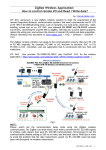
1
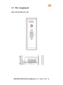
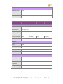
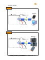
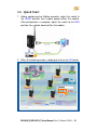
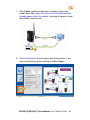
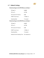
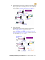
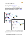
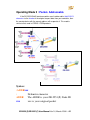
ZB-2550(P)/ZB-2551(P) User Manual Warranty All products manufactured by ICP DAS are under warranty regarding defective materials for a period of one year, beginning from the date of delivery to the original purchaser. Warning! ICP DAS assumes no liability for any damage resulting from the use of this product. ICP DAS reserves the right to change this manual at any time without notice. The information furnished by ICP DAS is believed to be accurate and reliable. However, no responsibility is assumed by ICP DAS for its use, not for any infringements of patents or other rights of third parties resulting from its use. Copyright Copyright @ 2007 by ICP DAS Co., Ltd. All rights are reserved. Trademark The names used for identification only may be registered trademarks of their respective companies. ZB-2550(P)/ZB-2551(P) User Manual Ver1.0, March /2009 ---1 Table of Contents 1. Introduction ..................................................................................................... 3 1.1 More Information .................................................................................... 4 1.2 Pin Assignment ........................................................................................ 6 1.3 Specifications............................................................................................. 7 1.4 Block Diagram......................................................................................... 9 1.5 Wire Connection.................................................................................... 10 1.6 Quick Start ............................................................................................. 12 Zigbee Addressing and Identifiers................................................. 16 1.7 2. Default Settings........................................................................................ 17 Applications .................................................................................................. 18 2.1 Operating Modes .................................................................................. 18 Operating Mode ............................................................................. 18 2.2 Application Example ............................................................................. 20 Operating Mode 1 : Transparent ......................................................... 20 Operating Mode 2 : Packet ................................................................. 21 Operating Mode 3 : Packet- Addressable............................................ 22 2.3 ZigBee Network Groups ........................................................................ 23 ZB-2550(P)/ZB-2551(P) User Manual Ver1.0, March /2009 ---2 1. Introduction ZigBee is a specification based on the IEEE 802.15.4 standard for wireless personal area networks (WPANs). ZigBee operates in the ISM radio bands and its focus is to define a general-purpose, inexpensive, self-organizing, mesh network that can be used for industrial control, embedded sensing, medical data collection, smoke and intruder warning, building automation, home automation, and domotics, etc. At present, the ICP DAS ZigBee converter ZB-2550 and ZB-2551, supports the RS-232 and RS-485 interfaces. The main design goal is limited data communication using wireless transmission, so may provide a better solution for environments where wiring is difficult. ZB-2550(P)/ZB-2551(P) User Manual Ver1.0, March /2009 ---3 1.1 More Information The ZB-2550 and the ZB-2551 are small-sized wireless ZigBee converters based on the IEEE 802.15.4 standard. They allow RS-485/RS-232 interfaces to be converted to a ZigBee wireless network. Only one ZB-2550 (Host) is allowed in a ZigBee network and is used to initialize and manage the data transmission routes. The ZB-2551 (Slave) ZigBee router is responsible for transmitting/receiving data from its child/parent router or the host. ICP DAS ZigBee products are designed for low data rates. The main benefit of ICP DAS ZigBee products is that they can be used to define a general-purpose, self-organizing mesh network, which can be highly advantageous for industrial control. The typical transmission range of the ICP DAS Zigbee ZB-2550/ZB-2551 converter is 100m, and the ZB-2550P/ZB-2551P is 700m. ZB-2550(P)/ZB-2551(P) User Manual Ver1.0, March /2009 ---4 The transmission frequency range of the ZigBee converter is between 2.405 GHz and 2.48 GHz, separated into 5 MHz sectors, and provides 16 channels, and 65536 Pan IDs (65535 network groups can be set). The ZigBee converter includes a repeater module that can be used to increase communication range or prevent data loss if the connection is interrupted or becomes unstable. Please refer to ZigBee converter other document for more information as following links: http://ftp.icpdas.com/pub/cd/usbcd/napdos/zigbee/zigbee_converter/ ZB-2550(P)/ZB-2551(P) User Manual Ver1.0, March /2009 ---5 1.2 Pin Assignment ZB-2050(P)/ZB-2051(P) ZB-2550(P)/ZB-2551(P) User Manual Ver1.0, March /2009 ---6 1.3 Specifications Models ZB-2550 ZB-2550P ZB-2551 ZB-2551P Wireless RF channels 16 Receive sensitivity -102 dBm Transmit power 12 dBm Network Topology Star, Mesh and Cluster tree support Certification TUV(ZCP) Antenna 2.4GHz - 3dBi Omni-Directional antenna Transmission Range Models 100m 700m 100m 700m ZB-2550 ZB-2550P ZB-2551 ZB-2551P General CPU 8-bit microcontroller EEPROM 128 KB (8 blocks, each block has 256 bytes);Data retention > 40 years; 1,000,000 erase/write cycles Module Type Host Host Slave Slave Communication Interface COM 0 RS-232 (TXD, RXD and GND); RS-232 (TXD, RXD and GND); D-SUB9 Female, Non-isolated D-SUB9 Male, Non-isolated RS-485 (D+, D-; internal ASIC self-tuner); Non-isolated COM 0 Settings Data Bit 8 Parity Even, Odd, None Stop Bit 1, 2 ZB-2550(P)/ZB-2551(P) User Manual Ver1.0, March /2009 ---7 LED Indicators ZigBee Net State Green ZigBee RxD Yellow Power Red Models ZB-2550P ZB-2550 ZB-2551 ZB-2551P Power Protection Power reverse polarity protection EMS Protection ESD, Surge, EFT Required Supply +10 VDC ~ +30 VDC Voltage Power Consumption 0.5W Connection 2W (max) 0.5W 2W (max) 5-Pin 5.08 mm Removable Terminal Block Mechanical Casing Plastic Flammability UL 94V-0 materials Dimensions 33 mm x 78 mm x 107 mm (W x L x H) Installation DIN-Rail Environment Operating -25 °C ~ +75 °C Temperature Storage -40 °C ~ +80 °C Temperature Relative Humidity 5 ~ 95% RH, non-condensing ZB-2550(P)/ZB-2551(P) User Manual Ver1.0, March /2009 ---8 1.4 Block Diagram ZB-2050/ZB-2551 ZB-2050P/ZB-2551P ZB-2550(P)/ZB-2551(P) User Manual Ver1.0, March /2009 ---9 1.5 Wire Connection Serial Port - RS-232 ZB-2550(P) Controller RS-232 (Female) CA-0915 ZB-2551(P) Remote I/O RS-232 (Male) CA-0910N ZB-2550(P)/ZB-2551(P) User Manual Ver1.0, March /2009 ---10 Serial Port - RS-485 ZB-2550(P) Controller RS-485 (D+, D-) D+ D- +10~+30 VDC GND ZB-2551(P) Remote I/O RS-485 (D+, D-) D+ D- +10~+30 VDC GND ZB-2550(P)/ZB-2551(P) User Manual Ver1.0, March /2009 ---11 1.6 Quick Start 1. Before configuring the ZigBee converter, adjust the switch to the ZBSET position then re-boot (power off/on) the module. After configuration is complete, adjust the switch to the RUN position then re-boot (power off/on) the module. 1 2. When the following screen is displayed, click on the OK button 2 ZB-2550(P)/ZB-2551(P) User Manual Ver1.0, March /2009 ---12 3. Click on the Connect button 3 4. Please select the COM Port on your PC 4 ZB-2550(P)/ZB-2551(P) User Manual Ver1.0, March /2009 ---13 5. Click on the Config button to configure setting for the ZigBee Converter - ZB-2550(P)/ZB-2551(P). e.g : ZB-2551(P) 5 6. Click on the Config button for set the new ZigBee setting. 6 ZB-2550(P)/ZB-2551(P) User Manual Ver1.0, March /2009 ---14 7. After ZigBee module configuration has been successfully established. Now, adjust the switch to the RUN position then re-boot (power off/on) the module. Leverage the power of your data. Make it work for you. 7 8. Click Default button to load factory default parameters if you want to load factory default setting of ZigBee Module 8 ZB-2550(P)/ZB-2551(P) User Manual Ver1.0, March /2009 ---15 Zigbee Addressing and Identifiers Node ID (0x0000~0xFFFF) A 16-bit address that describes a Zigbee node Randomly assigned during network join ZB-2570(P)/ZB-2550(P) always uses 0x0000 ZB-2571(P)/ZB-2551(P) ranges 0x0001~0xFFFF ZB-DIO/ZB-AIO ranges 0x0001~0x001F Resolve by stack in case of collision Included in all message to identify node Pan ID (0x0000~0xFFFF) A 16-bit ID to identify the network Included in every packet A “logical” way to separate Zigbee networks running on same RF channel Defined during network formation by ZB-2570(P)/ZB-2550(P) ZB-DIO/ZB-AIO always uses 0xFF00 or 0xFF01 RF Channel 1 of 16 RF channels Defined during network formation by ZB-2570(P)/ZB-2550(P) Note : A Work Network - Runing on the same Pan ID and RF Channel Network Survival Detecting Time ZB-2551(P) will connect with Parent (ZB-2550(P)) periodically to confirm the survival of network. If it detects unsuccessfully, and it process initialize network again to find a new parent. ZB-2550(P)/ZB-2551(P) User Manual Ver1.0, March /2009 ---16 1.7 Default Settings Default settings for the ZB-2550 are as follows: : ZB Node ID: 0x0000 ZB Pan ID: 0xFF00 ZB Channel (RF Channel): 0x00 ZBSET Data Format: 115200,n,8,1 Operating Mode: Transparent Default settings for the ZB-2551 are as follows: : ZB Node ID: 0x0020 ZB Pan ID: 0xFF00 ZB Channel (RF Channel): 0x00 ZBSET Data Format: 115200,n,8,1 Operating Mode: Transparent Network Survival Detecting Time: 20 second (0x14) ZB-2550(P)/ZB-2551(P) User Manual Ver1.0, March /2009 ---17 2. Applications 2.1 Operating Modes Interface Serial Port (RS-232/RS-485) Operating Modes Operating Mode 1 Transparent Operating Mode 2 Packet Operating Mode 3 Packet- Addressable Operating Mode Transparent (Original packet will be broken down into many small packets, each small packet is 50 Byte) Transparent mode lets you use the ZB-2550(P)/ZB-2551(P) module like a router. (Maximum original packet size is 200 Byte. Original packet must not more than 200 Byte, e.g “$01M” = 4 Byte) ZB-2550(P)/ZB-2551(P) User Manual Ver1.0, March /2009 ---18 Packet(Original packet won't be broken down into small packets) Bring original packet into a ICP DAS packet. The size of a ICP DAS packet is 200Byte. (Maximum original packet size is 200 Byte.) Packet-Addressable (Original packet won't be broken down into small packets) For Non-Addressable Device, such as barcode reader. Syntax, :ADDRxxx , the ADDR is your ZB-2551(P) Node ID. (Maximum original packet size is 200 Byte. Original packet must not more than 200 Byte, e.g “xxx” = 3 Byte) ZB-2550(P)/ZB-2551(P) User Manual Ver1.0, March /2009 ---19 2.2 Application Example Operating Mode 1 : Transparent If you wish to convert the RS-232/RS-485 interface to ZigBee and the device is addressable, such as the ICPDAS I-7000/M-7000/I-87k remote I/O modules, you can use the ZB-2551 (slave) to connect to these I/O modules and use the ZB-2550 (host) to connect to your controller or PC. If original packet size is less than 50 Byte most of the time, this Mode is the most suitable. In some applications where the host controller needs to broadcast data to all RS-232/RS-485 devices and these devices receive data only (no response), you can also use this mode. ZB-2550(P)/ZB-2551(P) User Manual Ver1.0, March /2009 ---20 Operating Mode 2 : Packet If you wish to convert the RS-232/RS-485 interface to ZigBee and the device is addressable, such as the ICPDAS I-7000/M-7000/I-87k remote I/O modules, you can use the ZB-2551 (slave) to connect to these I/O modules and use the ZB-2550 (host) to connect to your controller or PC. If original packet size is greater than 50 Byte most of the time, this Mode is the most suitable. In some applications where the host controller needs to broadcast data to all RS-232/RS-485 devices and these devices receive data only (no response), you can also use this mode. ZB-2550(P)/ZB-2551(P) User Manual Ver1.0, March /2009 ---21 Operating Mode 3 : Packet- Addressable If the RS-232/RS-485 interface modules aren’t addressable. Add 5 ASCII characters to the header of the original request data from your controller, then the remote device with the correct address will respond to it. This mode is similar to that used in ICPDAS I-752N products. Syntax: :ADDRxxx : Delimiter character ADDR The ADDR is your ZB-2551(P) Node ID xxx xxx is your original packet ZB-2550(P)/ZB-2551(P) User Manual Ver1.0, March /2009 ---22 2.3 ZigBee Network Groups ZB-2550(P)/ZB-2551(P) User Manual Ver1.0, March /2009 ---23 If original packet size is less than 50 Byte most of the time, Operating Mode Transparent is the most suitable. If original packet size is greater than 50 Byte most of the time, Operating Mode Packet is the most suitable. If you want to transmit more than 200 Byte one Packet or high-speed rate, please order a advanced ZigBee Converter ZB-2570 and ZB-2571 ZB-2550(P)/ZB-2551(P) User Manual Ver1.0, March /2009 ---24 Technical Support If you have problems about using the ZB-2000 series modules, please contact ICP DAS Product Support. Email: [email protected] ZB-2550(P)/ZB-2551(P) User Manual Ver1.0, March /2009 ---25