1
WT3000 Manual, Vol 2/3
WT3000
Precision Power Analyzer
Communication Interface
IM 760301-17E
5th Edition
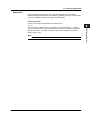
Thank you for purchasing the WT3000 Precision Power Analyzer.
This Communication Interface User’s Manual describes the functions of the GP-IB, RS232, USB, and Ethernet interfaces and communication commands. To ensure correct
use, please read this manual thoroughly before beginning operation. After reading the
manual, keep it in a convenient location for quick reference whenever a question arises
during operation.
Three manuals, including this one, are provided as manuals for the WT3000. Please
read all of them.
Manual Title
Manual No.
Description
WT3000 Precision Power Analyzer IM 760301-01E
User’s Manual
(Vol 1/3)
Explains all functions and
procedures of the WT3000
excluding the expansion functions and
communication functions.
WT3000 Precision Power Analyzer IM 760301-17E
Communication Interface
User’s Manual (CD-ROM)
(Vol 2/3)
This manual. Explains the
functions for controlling the
WT3000 using communication
commands.
WT3000 Precision Power Analyzer IM 760301-51E
Expansion Function User’s Manual
(Vol 3/3)
Explains the expansion functions
(motor evaluation function and options)
of the WT3000 and their operating
procedures.
Note
• The contents of this manual are subject to change without prior notice as a result of
continuing improvements to the instrument’s performance and functions. The figures
given in this manual may differ from those that actually appear on your screen.
• Every effort has been made in the preparation of this manual to ensure the accuracy
of its contents. However, should you have any questions or find any errors, please
contact your nearest YOKOGAWA dealer.
• Copying or reproducing all or any part of the contents of this manual without the
permission of Yokogawa Electric Corporation is strictly prohibited.
• The TCP/IP software of this product and the document concerning the TCP/IP
software have been developed/created by YOKOGAWA based on the BSD
Networking Software, Release 1 that has been licensed from University of California.
USB Interface and Ethernet Interface
• The items below are needed on the PC to use the communication functions via the
USB interface.
• DL/WT series library (TMCTL)
• USB connection device driver between the PC and WT3000
• The item below is needed on the PC to use the communication functions via the
Ethernet interface.
• DL/WT series library (TMCTL)
The library and driver above can be downloaded from the following Web page.
http://www.yokogawa.com/tm/
5th Edition : March 2006 (YK)
All Rights Reserved, Copyright © 2004 Yokogawa Electric Corporation
IM 760301-17E
i
Trademarks
• Microsoft, Internet Explorer, MS-DOS, Windows, Windows NT, and Windows XP are
either registered trademarks or trademarks of Microsoft Corporation in the United
States and/or other countries.
• Adobe, Acrobat, and PostScript are trademarks of Adobe Systems Incorporated.
• For purposes of this manual, the TM and ® symbols do not accompany their
respective trademark names or registered trademark names.
• Other company and product names are trademarks or registered trademarks of their
respective holders.
Revisions
•
•
•
•
•
ii
1st Edition
2nd Edition
3rd Edition
4th Edition
5th Edition
December 2004
June 2005
January 2006
December 2006
March 2007
IM 760301-17E
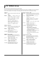
Structure of the Manual
This User’s Manual consists of the following sections:
Chapter 1
GP-IB Interface
Describes the functions and specifications of the GP-IB interface.
Chapter 2
RS-232 Interface (Option)
Describes the functions and specifications of the RS-232 interface.
Chapter 3
USB Interface (Option)
Describes the functions and specifications of the USB interface.
Chapter 4
Ethernet Interface (Option)
Describes the functions and specifications of the Ethernet interface.
Chapter 5
Before Programming
Describes the syntax used to transmit commands.
Chapter 6
Communication Commands
Describes all the commands one by one.
Chapter 7
Status Reports
Describes the status byte, various registers, queues, and other
information.
Appendix
Describes reference material such as an ASCII character code table.
Index
IM 760301-17E
iii
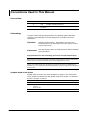
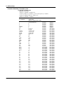
Conventions Used in This Manual
Unit and Note
Type
Symbol
Meaning
Unit
k
K
1000
1024
Note
Note
Calls attention to information that is important for proper operation of the
instrument.
Example: 100 kHz
Example: 640 KB (file data size)
Subheadings
On pages that describe operating procedures, the following symbols, displayed
characters, and terminology are used to distinguish the procedures from their
explanations:
Procedure
Follow the numbered steps. All procedures are written with
inexperienced users in mind; experienced users may not need to
carry out all the steps.
Explanation
This subsection describes the setup parameters and the limitations
on the procedures.
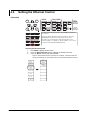
Displayed Characters and Terminology Used in the Procedural Explanations
Panel Keys and Soft keys
Bold characters used in the procedural explanations indicate characters that are marked on the
panel keys or the characters of the soft keys or menus displayed on the screen.
SHIFT + Panel Key
SHIFT + key means you will press the SHIFT key to turn ON the SHIFT key followed by the
operation key. The setup menu marked in purple below the panel key that you pressed appears
on the screen.
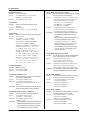
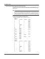
Symbols Used in the Syntax
Symbols which are used in the syntax descriptions in Chapter 6 are shown below.
These symbols are referred to as BNF (Backus-Naur Form) symbols. For details on
the data, see pages 5-5 and 5-6.
iv
Symbol
Meaning
Example
< >
Defined value.
ELEMent<x>
Example of Input
{ }
MODE:{RMS|MEAN|DC|RMEAN}? ->MODE:RMS?
|
Select from values
given in { }.
Exclusive OR
[ ]
Can be omitted.
NUMeric[:NORMal]:VALue?
<x> = 1 to 4
->ELEMENT2
->NUMERIC:VALUE?
IM 760301-17E
1
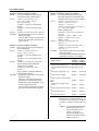
Contents
Structure of the Manual .................................................................................................................. iii
Conventions Used in This Manual .................................................................................................. iv
2
Chapter 1 GP-IB Interface
1.1
1.2
1.3
1.4
1.5
1.6
Names and Functions of Parts ......................................................................................... 1-1
GP-IB Interface Functions ................................................................................................ 1-2
GP-IB Interface Specifications ......................................................................................... 1-3
Connecting the GP-IB Cable ............................................................................................ 1-4
Setting the GP-IB Control ................................................................................................ 1-5
Responses to Interface Messages ................................................................................... 1-6
Chapter 2 RS-232 Interface (Option)
2.1
2.2
2.3
2.4
2.5
2.6
Names and Functions of Parts ......................................................................................... 2-1
RS-232 Interface Functions and Specifications ............................................................... 2-2
Connection via the RS-232 Interface ............................................................................... 2-3
Combination of Handshaking Methods ............................................................................ 2-5
Combination of Data Formats .......................................................................................... 2-7
Setting the RS-232 Control .............................................................................................. 2-8
Chapter 3 USB Interface (Option)
3.1
3.2
3.3
3.4
Names of Parts ................................................................................................................ 3-1
USB Interface Functions and Specifications .................................................................... 3-2
Connection via the USB Interface .................................................................................... 3-3
Setting the USB Control ................................................................................................... 3-4
3
4
5
6
7
App
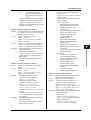
Chapter 4 Ethernet Interface (Option)
4.1
4.2
4.3
Names and Functions of Parts ......................................................................................... 4-1
Ethernet Interface Functions and Specifications .............................................................. 4-2
Setting the Ethernet Control ............................................................................................. 4-4
Chapter 5 Before Programming
5.1
5.2
5.3
5.4
5.5
Messages ......................................................................................................................... 5-1
Commands ....................................................................................................................... 5-3
Responses ....................................................................................................................... 5-4
Data ................................................................................................................................. 5-5
Synchronization with the Controller ................................................................................. 5-7
Chapter 6 Communication Commands
6.1
6.2
6.3
6.4
6.5
6.6
6.7
6.8
6.9
6.10
6.11
6.12
IM 760301-17E
A List of Commands ......................................................................................................... 6-1
ACQuisition Group ......................................................................................................... 6-17
AOUTput Group ............................................................................................................. 6-19
CBCycle Group .............................................................................................................. 6-21
COMMunicate Group ..................................................................................................... 6-24
CURSor Group ............................................................................................................... 6-26
DISPlay Group ............................................................................................................... 6-29
FILE Group .................................................................................................................... 6-47
FLICker Group ............................................................................................................... 6-52
HARMonics Group ......................................................................................................... 6-57
HCOPy Group ................................................................................................................ 6-59
HOLD Group .................................................................................................................. 6-63
v
Index
Contents
6.13
6.14
6.15
6.16
6.17
6.18
6.19
6.20
6.21
6.22
6.23
6.24
IMAGe Group ................................................................................................................. 6-64
INPut Group ................................................................................................................... 6-66
INTEGrate Group ........................................................................................................... 6-74
MEASure Group ............................................................................................................. 6-76
MOTor Group ................................................................................................................. 6-81
NUMeric Group .............................................................................................................. 6-84
RATE Group ................................................................................................................. 6-102
STATus Group .............................................................................................................. 6-103
STORe Group .............................................................................................................. 6-105
SYSTem Group ............................................................................................................ 6-109
WAVeform Group ......................................................................................................... 6-112
Common Command Group .......................................................................................... 6-114
Chapter 7 Status Reports
7.1
7.2
7.3
7.4
7.5
Status Reports ................................................................................................................. 7-1
Status Byte ....................................................................................................................... 7-3
Standard Event Register .................................................................................................. 7-5
Extended Event Register ................................................................................................. 7-7
Output Queue and Error Queue ....................................................................................... 7-9
Appendix
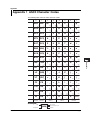
Appendix 1 ASCII Character Codes ....................................................................................... App-1
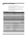
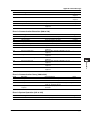
Appendix 2 Error Messages ................................................................................................... App-2
Appendix 3 IEEE 488.2-1992 ................................................................................................. App-5
Index
vi
IM 760301-17E
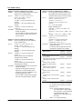
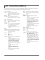
Chapter 1
1.1
GP-IB Interface
1
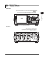
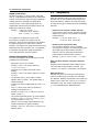
Names and Functions of Parts
GP-IB Interface
2
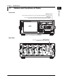
Front Panel
REMOTE indicator
Turns ON when the WT3000 is in the remote mode (controlled via communications).
LOCAL key
Press this key to clear the remote mode (controlled via communications)
and enter the local mode in which key operations are enabled.
YOKOGAWA WT3000
3
PRECISION POWER ANALYZER
VOLTAGE RANGE
ELEMENT
ESC
1
2
3
4
EXT SENSOR
CURRENT RANGE
SENSOR RATIO
4
ELEMENT
ALL
COMPEN
MEASURING
RMS
WIRING
MEAN
DC
MEASURING
MODE
RMEAN
AUTO
RMS
MEAN
DC
RMEAN
MODE
AUTO
INPUT INFO.
RESET
SET
LCD
DISPLAY
NUMERIC
ITEM & ELEMENT
WAVE
REMOTE
UPDATE
RATE
U/ I / P
WP/q/
TIME
OTHERS
HOLD
LOCAL
5
SINGLE
CAL
PAGE
PAGE
LINE FILTER
SCALING
MOTOR
SET
FREQ
FILTER
HRM SET
MEASURE
PRINT
FORM
USER
ELEMENT
LOWER FORM
USER SET
ALL
INTEG
START
STOP
SHIFT
AVG
SYNC SOURCE
CURSOR
FILE
ITEM
LOWER ITEM
NULL
IMAGE SAVE
STORE
MENU
STORE SET
MISC
HELP
6
MENU
MISC key
Press this key to configure communications.
7
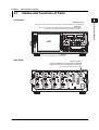
Rear Panel
GP-IB connector
Connector used to connect the WT3000 to the
controller (PC) using a GP-IB cable.
ELEMENT
VOLTAGE
ELEMENT
1
VOLTAGE
ELEMENT
2
VOLTAGE
ELEMENT
3
VOLTAGE
4
App
SERIAL
(RS-232) / USB
D/A OUTPUT
Index
TORQUE
±
±
±
1000V MAX
1000VMAX
CURRENT
1000VMAX
EXT
±
1000V MAX
CURRENT
1000V MAX
1000VMAX
EXT
CURRENT
1000V MAX
± 20V MAX
EXT. CLK
1000VMAX
EXT
CURRENT
EXT
SPEED
GP-IB
(IEEE488)
ETHERNET
100BASE-TX
MEAS. START
± 20V MAX
42Vpk MAX
30A MAX
30A MAX
30A MAX
±
±
±
ALL TERMINALS
1000V MAX TO
IM 760301-17E
CAT II
ALL TERMINALS
1000V MAX TO
CAT II
VIDEO-OUT
(VGA)
30A MAX
±
ALL TERMINALS
1000V MAX TO
CAT II
ALL TERMINALS
1000V MAX TO
CAT II
100-240V AC
50/60Hz
200VA MAX
FUSE 250V T 6.3A
1-1
1.2
GP-IB Interface Functions
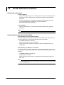
GP-IB Interface Functions
Listener Capability
• All of the information that you can set with the panel keys can be set through the GPIB interface except for turning ON/OFF the power and setting the communication
parameters.
• Receives commands from a controller requesting the output of setup parameters,
measured/computed data, waveform data, and other information.
• Also receives status report commands.
Talker Capability
• Outputs setup parameters, measured/computed data, waveform data, and other
information.
Note
Talk-only, listen-only, and controller functions are not available on this instrument.
Switching between Remote and Local Modes
When Switching from Local to Remote Mode
Receiving a REN (Remote Enable) message from the controller when the instrument is
in the local mode causes the instrument to switch to the remote mode.
• The REMOTE indicator is turned ON.
• All keys except the LOCAL key are disabled.
• Settings entered in local mode are retained even when the WT3000 switches to
remote mode.
When Switching from Remote to Local Mode
Pressing LOCAL key in remote mode puts the instrument in local mode. However, this
act is invalid if the instrument has been set to Local Lockout mode (see page 1-6) by the
controller.
• The REMOTE indicator is turned OFF.
• Key operations are enabled.
• Settings entered in remote mode are retained even when the WT3000 switches to
local mode.
Note
The GP-IB interface cannot be used simultaneously with other communication interfaces (RS232, USB, or Ethernet).
1-2
IM 760301-17E
1.3
1
GP-IB Interface Specifications
Supported device:
National Instruments
• AT-GPIB
• PCI-GPIB and PCI-GPIB+
• PCMCIA-GPIB and PCMCIA-GPIB +
NI-488.2M driver version 1.60 or later
Electrical and mechanical specifications: Conforms to IEEE St’d 488-1978
Functional specifications:
See table below.
Protocol:
Conforms to IEEE St’d 488.2-1992
Code used:
ISO (ASCII) code
Mode:
Addressable mode
Address setting:
The address can be set in the range from 0 to
30.
Clear remote mode:
Remote mode can be cleared by pressing
LOCAL key except when the instrument has
been set to Local Lockout mode by the
controller.
Functional specifications
IM 760301-17E
GP-IB Interface
2
GP-IB Interface Specifications
Subset Name
Description
Source handshaking
SH1
Full source handshaking capability.
Acceptor handshaking
AH1
Full acceptor handshaking capability.
Talker
T6
Basic talker capability, serial polling, untalk on
MLA (My Listen Address), and no talk-only
capability.
Listener
L4
Basic listener capability, unlisten on MTA (My
Talk Address), and no listen-only capability.
Service request
SR1
Full service request capability
RL1
Full remote/local capability
Parallel polling
PP0
No parallel polling capability
Device clear
DC1
Full device clear capability
Device trigger
DT1
Full device trigger capability
Controller
C0
No controller capability
Electrical characteristics
E1
Open collector
4
5
6
7
Function
Remote local
3
1-3
App
Index
1.4
Connecting the GP-IB Cable
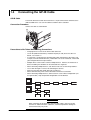
GP-IB Cable
The GP-IB connector used on this instrument is a 24-pin connector that conforms to the
IEEE St’d 488-1978. Use a GP-IB cable that conforms to this standard.
Connection Procedure
Connect the cable as shown below.
TO
RQ
UE
D/A
OU
TP
UT
V
MA
S
(R ERI
S
X
SP
EE
D
G
(IEP- IB
EE
488)
0V
MA
X
42V
pk
MA
CL
K
X
VID
E
(V O-OU
GA) T
ETH
100 ER
BA NET
SE
-TX
STA
RT
10020 24
FU0VA0V
SE M AC
AX
250V
5
T
6.2
Precautions to Be Taken When Making Connections
• Firmly tighten the screws on the GP-IB cable connector.
• Use an NI (National Instruments) model GP-IB port (or card) on the PC side. For
details, see section 1.3.
• If a converter is used along the communication cable connecting the WT and PC (for
example, a GP-IB-to-USB converter), malfunctions can occur. For details, consult with
your Yokogawa dealer or representative.
• Multiple cables can be used to connect multiple devices. However, no more than 15
devices including the controller can be connected on a single bus.
• When connecting multiple devices, each device must have its own unique address.
• Use a cable of length 2 m or less for connecting the devices.
• Make sure the total cable length does not exceed 20 m.
• When communicating, have at least two-thirds of the devices turned ON.
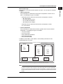
• When connecting multiple devices, connect them in a star or linear configuration (see
the figure below). Loop and parallel configurations are not allowed.
CAUTION
When connecting or disconnecting communication cables, make sure to turn
OFF the PC and the WT3000. Otherwise, erroneous operation or damage to
the internal circuitry may result.
1-4
IM 760301-17E
1.5
1
Setting the GP-IB Control
GP-IB Interface
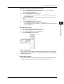
Procedure
RESET
SET
DISPLAY
NUMERIC
Cursor keys
2
ITEM & ELEMENT
WAVE
OTHERS
REMOTE
U/ I / P
UPDATE
RATE
WP/q/
TIME
SINGLE
HOLD
LOCAL
3
CAL
PAGE
PAGE
SCALING
LINE FILTER
MOTOR
SET
FREQ
FILTER
HRM SET
MEASURE
SYNC SOURCE
CURSOR
NULL
FILE
IMAGE SAVE
STORE
MENU
STORE SET
PRINT
MISC
HELP
AVG
ITEM
FORM
USER
ELEMENT
LOWER ITEM
LOWER FORM
USER SET
ALL
INTEG
START
STOP
SHIFT
4
To exit the menu during operation, press ESC located above
the soft keys.
In the procedural explanation below, the phrase “press the
cursor keys” may be used. This phrase refers to the
procedures for selecting items and entering values and
character strings. For details on the procedures, see section
3.14 in the User’s Manual IM760301-01E.
5
MENU
1.
2.
3.
6
Press MISC to display the Misc menu.
Press the Remote Control soft key to display the Remote Ctrl menu.
Press the Device soft key to select GP-IB.
Only the communication interface selected here is enabled. The WT3000 does not
accept commands that are transmitted to other unselected communication interfaces.
4.
7
Press the cursor keys to set the address.
App
Index
Explanation
Enter the following settings when using a controller to set information that can be
specified through key operation on the WT3000 or when outputting setup parameters or
output waveform display data to the controller.
Address
Set the address of the WT3000 within the following range for the addressable mode.
0 to 30
Each device that can be connected via GP-IB has a unique address within the GP-IB
system. This address is used to distinguish the device from others. Therefore, when
you connect the WT3000 to a PC, for example, make sure to assign a unique address to
the WT3000.
Note
Do not change the address while the controller or other devices are using the GP-IB system.
IM 760301-17E
1-5
1.6
Responses to Interface Messages
Responses to Interface Messages
Responses to a Uni-Line Message
• IFC (Interface Clear)
Clears the talker and listener functions. Stops output if data are being output.
• REN (Remote Enable)
Switches between the remote and local modes.
IDY (Identify) is not supported.
Responses to a Multi-Line Message (Address Command)
• GTL (Go To Local)
Switches to the local mode.
• SDC (Selected Device Clear)
• Clears the program message (command) being received and the output queue
(see page 7-9).
• *OPC and *OPC? commands in execution are void.
• The *WAI and COMMunicate:WAIT commands are immediately terminated.
• GET (Group Execute Trigger)
Same operation as the *TRG command.
PPC (Parallel Poll Configure) and TCT (Take Control) are not supported.
Responses to a Multi-Line Message (Universal Command)
• LLO (Local Lockout)
Disables LOCAL on the front panel to prohibit switching to the local mode.
• DCL (Device Clear)
Same operation as the SDC message.
• SPE (Serial Poll Enable)
Sets the talker function on all devices on the bus to serial polling mode. The controller
polls the devices in order.
• SPD (Serial Poll Disable)
Clears the serial polling mode of the talker function on all devices on the bus.
PPU (Parallel Poll Unconfigure) is not supported.
What Is an Interface Message
Interface messages are also referred to as interface commands or bus commands. They
are commands that are issued by the controller. They are classified as follows:
Uni-Line Messages
A single control line is used to transmit uni-line messages. The following three types are
available.
• IFC (Interface Clear)
• REN (Remote Enable)
• IDY (Identify)
1-6
IM 760301-17E
1.6 Responses to Interface Messages
• Commands that are valid on an instrument that is designated as a listener
• GTL (Go To Local)
• SDC (Selected Device Clear)
• PPC (Parallel Poll Configure)
• GET (Group Execute Trigger)
1
GP-IB Interface
Multi-Line Messages
Eight data lines are used to transmit multi-line messages. The messages are classified
as follows:
• Address Commands
These commands are valid when the instrument is designated as a listener or as a
talker. The following five types are available.
2
3
4
• Commands that are valid on an instrument that is designated as a talker
TCT (Take Control)
5
• Universal Commands
These commands are valid on all instruments regardless of the listener and talker
designations. The following five types are available.
• LLO (Local Lockout)
• DCL (Device Clear)
• PPU (Parallel Poll Unconfigure)
• SPE (Serial Poll Enable)
• SPD (Serial Poll Disable)
6
7
In addition, listener address, talker address, and secondary commands are also
considered interface messages.
Uni-line
messages
Address
commands
Universal
commands
Index
★IFC
★REN
IDY
Listener
address
App
Interface messages
Multi-line messages
★GTL
★SDC
PPC
★GET
TCT
Talker
address
★LLO
★DCL
PPU
★SPE
★SPD
Secondary
commands
Interface messages that WT3000 supports are indicated with ★ marks.
Note
The differences between SDC and DCL
In multi-line messages, SDC messages are those that require talker or listener designation
and DCL messages are those that do not require the designation. Therefore, SDC messages
are directed at a particular instrument while DCL messages are directed at all instruments on
the bus.
IM 760301-17E
1-7
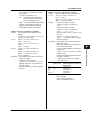
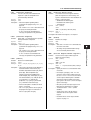
Chapter 2
2.1
RS-232 Interface (Option)
1
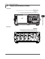
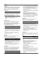
Names and Functions of Parts
2
Front Panel
RS-232 Interface (Option)
REMOTE indicator
Turns ON when the WT3000 is in the remote mode (controlled via communications).
LOCAL key
Press this key to clear the remote mode (controlled via communications)
and enter the local mode in which key operations are enabled.
YOKOGAWA WT3000
3
PRECISION POWER ANALYZER
VOLTAGE RANGE
ELEMENT
ESC
1
2
3
4
EXT SENSOR
CURRENT RANGE
SENSOR RATIO
4
ELEMENT
ALL
COMPEN
MEASURING
RMS
WIRING
MEAN
DC
MEASURING
MODE
RMEAN
AUTO
RMS
MEAN
DC
RMEAN
MODE
AUTO
INPUT INFO.
RESET
SET
LCD
DISPLAY
NUMERIC
ITEM & ELEMENT
WAVE
OTHERS
REMOTE
U/ I / P
UPDATE
RATE
WP/q/
TIME
SINGLE
HOLD
LOCAL
5
CAL
PAGE
PAGE
SCALING
LINE FILTER
MOTOR
SET
FREQ
FILTER
MEASURE
FILE
IMAGE SAVE
STORE
MENU
STORE SET
MISC
HELP
PRINT
FORM
USER
ELEMENT
LOWER FORM
USER SET
ALL
INTEG
START
STOP
SHIFT
AVG
HRM SET
CURSOR
ITEM
LOWER ITEM
SYNC SOURCE
NULL
6
MENU
MISC key
Press this key to configure communications.
7
Rear Panel
RS-232 connector
EIA-574 compliant: For the 9-pin EIA-232 (RS-232)
Connector used to connect the WT3000 to the controller
(PC) using an RS-232 interface cable.
ELEMENT
VOLTAGE
ELEMENT
1
VOLTAGE
ELEMENT
2
VOLTAGE
ELEMENT
3
VOLTAGE
4
App
Index
SERIAL
(RS-232) / USB
D/A OUTPUT
TORQUE
±
±
±
1000V MAX
1000VMAX
CURRENT
1000V MAX
1000VMAX
EXT
±
CURRENT
1000V MAX
1000VMAX
EXT
CURRENT
1000V MAX
± 20V MAX
EXT. CLK
1000VMAX
EXT
CURRENT
EXT
SPEED
GP-IB
(IEEE488)
ETHERNET
100BASE-TX
MEAS. START
± 20V MAX
42Vpk MAX
30A MAX
30A MAX
30A MAX
30A MAX
±
±
±
±
CAT II
ALL TERMINALS
1000V MAX TO
IM 760301-17E
CAT II
ALL TERMINALS
1000V MAX TO
CAT II
ALL TERMINALS
1000V MAX TO
VIDEO-OUT
(VGA)
CAT II
ALL TERMINALS
1000V MAX TO
100-240V AC
50/60Hz
200VA MAX
FUSE 250V T 6.3A
2-1
2.2
RS-232 Interface Functions and Specifications
Receiving Function
You can specify the same settings as those specified by front panel key operations.
Receives output requests for measured and computed data, setup parameters of the
panel, and error codes.
Sending Function
Outputs measured and computed data.
Outputs panel setup parameters and the status byte.
Outputs error codes that have occurred.
Switching between Remote and Local Modes
When Switching from Local to Remote Mode
If the WT3000 receives a “:COMMunicate:REMote ON” command from the PC when it
is in the local mode, it switches to the remote mode.
• The REMOTE indicator is turned ON.
• All keys except the LOCAL key are disabled.
• Settings entered in local mode are retained even when the WT3000 switches to
remote mode.
When Switching from Remote to Local Mode
Pressing LOCAL key in remote mode puts the instrument in local mode. However, this is
void when the WT3000 has received a “:COMMunicate:LOCKout ON” command from
the PC (local lockout condition). When the WT3000 receives a
“:COMMunicate:REMote OFF” command from the PC, the WT3000 switches to the
local mode regardless of the local lockout condition.
• The REMOTE indicator is turned OFF.
• Key operations are enabled.
• Settings entered in remote mode are retained even when the WT3000 switches to
local mode.
Note
The RS-232 interface cannot be used simultaneously with other communication interfaces
(GP-IB, USB, or Ethernet).
RS-232 Interface Specifications
Electrical characteristics:
Connection:
Transmission mode:
Synchronization:
Baud rate:
Start bit:
Data length:
Parity:
Stop bit:
Connector:
Hardware handshaking:
Software handshaking:
Received buffer length:
2-2
Conforms to EIA-574 (9-pin EIA-232 (RS-232))
Point-to-point
Full-duplex
Start-stop synchronization
1200, 2400, 4800, 9600, 19200, and 38400
Fixed to 1 bit
7 or 8 bits
Even, odd, or no parity
1 or 2 bits
DELC-J9PAF-13L6 (JAE or equivalent)
Select whether to fix the CA and CB signals to TRUE or use
the signals for flow control.
Select whether to use the X-ON and X-OFF signals to control
the transmission data or both transmission and reception data.
X-ON (ASCII 11H)
X-OFF (ASCII 13H)
256 bytes
IM 760301-17E
2.3
1
Connection via the RS-232 Interface
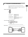
Connector and Signal Names
8
9
2
3
4
5
5
6
2 RD (Received Data):
3
5
7
8
*
Received data from the PC.
Signal direction ..... input
SD (Send Data):
Transmitted data to the PC.
Signal direction ..... output
SG (Signal Ground):
Signal ground.
RS (Request to Send): Handshaking signal to receive data from the PC.
Signal direction ..... output
CS (Clear to Send):
Handshaking signal to send data to the PC.
Signal direction ..... input
Pins 1, 4, 6, and 9 are not used.
7
App
9-Pin to 25-Pin Adapter and Signal Names
3 2 7
(2) (3) (4)
8
(5)
Index
5
(7)
The numbers inside the parentheses are pin numbers for the 25-pin connector.
Signal Direction
The following figure shows the direction of the signals used by the RS-232 interface of
the WT3000.
Computer
IM 760301-17E
3
4
1
6
7
2
RS-232 Interface (Option)
When you connect the WT3000 to a PC, you must set the WT3000 so that the
handshaking method, baud rate, data format, and other parameters match those on the
PC side.
For details on the settings, see the following pages. In addition, use an interface cable
that meets the specifications of the WT3000.
RS [Request to send]
7
CS [Clear to send]
8
SD [Send data]
3
RD [Receive data]
2
This
instrument
2-3
2.3 Connection via the RS-232 Interface
RS-232 Standard Signals and Their JIS and CCITT Abbreviations
Abbreviation
Pin No.
Description
(9-pin connector) Serial (RS-232)
CCITT
JIS
5
AB (GND)
102
SG
Signal ground
3
BA (TXD)
103
SD
Transmitted data
2
BB (RXD)
104
RD
Received data
7
CA (RTS)
105
RS
Request to send
8
CB (CTS)
106
CS
Clear to send
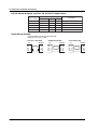
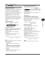
Signal Wiring Example
The pin numbers are for the 9-pin connector.
In general, use a cross cable.
• OFF-OFF / XON-XON
PC
SD
RD
RS
CS
SG
2-4
3
2
7
8
5
WT3000
3
2
7
8
5
SD
RD
RS
CS
SG
• XON-RTS(XON-RS)
PC
SD
RD
RS
CS
SG
3
2
7
8
5
• CTS-RTS(CS-RS)
WT3000
3
2
7
8
5
SD
RD
RS
CS
SG
PC
SD
RD
RS
CS
SG
3
2
7
8
5
WT3000
3
2
7
8
5
SD
RD
RS
CS
SG
IM 760301-17E
2.4
1
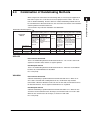
Combination of Handshaking Methods
Handshake format Descriptions→
Data Sending Control (control
method when sending data to a computer)
Hardware
Software
Handshake
Handshake
No
Sending stops Sending stops
when X-off is when CB(CTS) is handshake
received, and False, and
sending is
sending is
resumed
resumed when CB
when X-on is is True.
received.
Handshake
Method
The menu of
this instrument
OFF-OFF
NO-NO
XON-XON
XON-XON
XON-RS
XON-RTS
CS-RS
CTS-RTS
Data Receiving Control (control
method when receiving data from a computer)
Hardware
Software
Handshake
Handshake
No
X-off is sent
CA (RTS) is set to
handshake
when received False when
data buffer
received data buffer
becomes 3/4- is only 3/4-full, and
full, and X-on is is set to True when
sent when the received data buffer
received data is only 1/4-full.
buffer is only
1/4-full.
2
RS-232 Interface (Option)
When using the RS-232 interface for transferring data, it is necessary for equipment on
both sides to agree on a set of rules to ensure the proper transfer of data. The set of
rules is called handshaking. Because there are various handshaking methods that can
be used between the WT3000 and the PC, one must make sure that the same method is
chosen by both the WT3000 and the PC.
You can choose any of the four methods in the table below.
3
4
5
6
7
OFF-OFF
Data Transmission Control
There is no handshaking between the WT3000 and the PC. The “X-OFF” and “X-ON”
signals are treated as data, and the CS signal is ignored.
App
Data Reception Control
There is no handshaking between the WT3000 and the PC. When the received buffer
becomes full, all overflow data are discarded.
RS = True (fixed).
XON-XON
Data Transmission Control
Software handshaking is performed between the WT3000 and the PC. When an “XOFF” code is received while sending data to the PC, the WT3000 stops the data
transmission. When the WT3000 receives the next “X-ON” code, the WT3000 resumes
the data transmission. The CS signal received from the PC is ignored.
Data Reception Control
Software handshaking is performed between the WT3000 and the PC. When the free
area of the receive buffer decreases to 64 bytes, the WT3000 sends an “X-OFF” code.
When the free area increases to 192 bytes, it sends an “X-ON” code.
RS = True (fixed).
IM 760301-17E
2-5
Index
2.4 Combination of Handshaking Methods
XON-RS
Data Transmission Control
Software handshaking is performed between the WT3000 and the PC. When an “XOFF” code is received while sending data to the PC, the WT3000 stops the data
transmission. When the WT3000 receives the next “X-ON” code, the WT3000 resumes
the data transmission. The CS signal received from the PC is ignored.
Data Reception Control
Hardware handshaking is performed between the WT3000 and the PC. When the free
area of the receive buffer decreases to 64 bytes, the instrument sets “RS = False.”
When the free area increases to 192 bytes, it sets “RS = True.”
CS-RS
Data Transmission Control
Hardware handshaking is performed between the WT3000 and the PC. When the CS
signal becomes False while sending data to the PC, the WT3000 stops the data
transmission. When the CS signal becomes True, the WT3000 resumes the data
transmission. The “X-OFF” and “X-ON” signals are treated as data.
Data Reception Control
Hardware handshaking is performed between the WT3000 and the PC. When the free
area of the receive buffer decreases to 64 bytes, the instrument sets “RS = False.”
When the free area increases to 192 bytes, it sets “RS = True.”
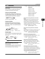
Precautions Regarding Data Reception Control
When handshaking is used to control the reception of data, data may still be sent from
the PC even if the free space in the receive buffer drops below 64 bytes. In this case,
after the receive buffer becomes full, the excess data will be lost, whether or not
handshaking is in effect. Data storage of data resumes when there is free space in the
buffer.
Data Receiving Control using Handshaking
256 bytes
When handshaking is in use,
reception of data will stop when the
free space in the buffer drops to 64
bytes since data cannot be passed to
Free, 64 bytes the main program fast enough to
keep up with the transmission.
Used
Used
Free, 192 bytes
Used
After reception of data stops, data
continues to be passed to the internal
program. Reception of data starts
again when the free space in the
buffer increases to 192 bytes.
Whether handshaking is in use or not,
if the buffer becomes full, any
additional data received is no longer
stored and is lost.
Note
The PC program must be designed so that the received buffers of both the WT3000 and the
PC do not become full.
2-6
IM 760301-17E
2.5
1
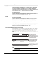
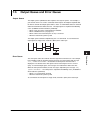
Combination of Data Formats
Level returns to idle
state (dotted line)
until the start bit of
the next item of data
(solid line).
1 character
Circuit idle state
Data bit
(7 or 8 bits)
Stop bit
Start bit
Parity bit
Even, odd or none
2
RS-232 Interface (Option)
The RS-232 interface of the WT3000 performs communications using start-stop
synchronization. In start-stop synchronization, characters are transmitted one at a time.
Each character consists of a start bit, data bits, a parity bit, and a stop bit (see the
following figure).
3
4
5
1
1 or 2 bits
2
6
7
App
Index
IM 760301-17E
2-7
2.6
Setting the RS-232 Control
Procedure
RESET
SET
DISPLAY
NUMERIC
Cursor keys
ITEM & ELEMENT
WAVE
OTHERS
REMOTE
U/ I / P
UPDATE
RATE
WP/q/
TIME
SINGLE
HOLD
LOCAL
CAL
PAGE
PAGE
SCALING
LINE FILTER
MOTOR
SET
FREQ
FILTER
HRM SET
MEASURE
SYNC SOURCE
CURSOR
NULL
FILE
PRINT
AVG
IMAGE SAVE
STORE
MENU
STORE SET
MISC
HELP
ITEM
FORM
USER
ELEMENT
LOWER ITEM
LOWER FORM
USER SET
ALL
INTEG
START
STOP
SHIFT
To exit the menu during operation, press ESC located above
the soft keys.
In the procedural explanation below, the phrase “press the
cursor keys” may be used. This phrase refers to the
procedures for selecting items and entering values and
character strings. For details on the procedures, see section
3.14 in the User’s Manual IM760301-01E.
MENU
Selecting the RS-232 Control
1.
Press MISC to display the Misc menu.
2.
Press the Remote Control soft key to display the Remote Ctrl menu.
3.
Press the Device soft key to select RS232.
Only the communication interface selected here is enabled. The WT3000 does not
accept commands that are transmitted to other unselected communication interfaces.
Selecting the Baud Rate
4.
Press the cursor keys to select Baud Rate.
Selecting the Data Format, Handshaking, and Terminator
4.
Press the Format (data format), Rx-Tx (handshaking), or Terminator soft key
and select the setting for the respective item.
2-8
IM 760301-17E
2.6 Setting the RS-232 Control
1
Explanation
Enter the following settings when using a controller to set information that can be
specified through key operation on the WT3000 or when outputting setup parameters or
output waveform data to the controller.
RS-232 Interface (Option)
Baud Rate
Select the baud rate from the following:
1200, 2400, 4800, 9600, 19200, or 38400
2
3
Data Format
Select the combination of data length, parity, and stop bit from the following:
8-NO-1, 7-EVEN-1, 7-ODD-1, or 7-NO-2
4
Handshaking Method
Select the transmit data control and receive data control from the following:
NO-NO, XON-XON, XON-RTS, or CTS-RTS
5
Terminator
Select the terminator from below. On the WT3000 menu, select the terminator that is
used when transmitting data from the WT3000. Use “Lf” or “Cr+Lf” for the terminator for
receiving data on the WT3000.
Cr, Lf, or Cr+Lf
6
7
App
Index
IM 760301-17E
2-9
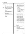
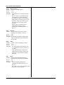
Chapter 3
3.1
USB Interface (Option)
1
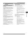
Names of Parts
Front Panel
2
REMOTE indicator
Turns ON when the WT3000 is in the remote mode (controlled via communications).
LOCAL key
Press this key to clear the remote mode (controlled via communications)
and enter the local mode in which key operations are enabled.
USB Interface (Option)
YOKOGAWA WT3000
3
PRECISION POWER ANALYZER
VOLTAGE RANGE
ELEMENT
ESC
1
2
3
4
EXT SENSOR
CURRENT RANGE
SENSOR RATIO
4
ELEMENT
ALL
COMPEN
MEASURING
RMS
WIRING
MEAN
DC
MEASURING
MODE
RMEAN
AUTO
RMS
MEAN
DC
RMEAN
MODE
AUTO
INPUT INFO.
RESET
SET
LCD
DISPLAY
NUMERIC
ITEM & ELEMENT
WAVE
OTHERS
REMOTE
U/ I / P
UPDATE
RATE
WP/q/
TIME
SINGLE
HOLD
LOCAL
5
CAL
PAGE
PAGE
SCALING
LINE FILTER
MOTOR
SET
FREQ
FILTER
HRM SET
MEASURE
CURSOR
FILE
PRINT
ITEM
FORM
USER
ELEMENT
LOWER ITEM
LOWER FORM
USER SET
ALL
INTEG
START
STOP
SHIFT
AVG
SYNC SOURCE
NULL
IMAGE SAVE
STORE
MENU
STORE SET
MISC
HELP
6
MENU
MISC key
Press this key to configure communications.
7
Rear Panel
USB connector for connecting to a PC
A connector used to connect the WT3000 to the controller
(such as a PC) using a USB cable. For the connection
procedure, see page 3-3.
ELEMENT
VOLTAGE
ELEMENT
1
VOLTAGE
ELEMENT
2
VOLTAGE
ELEMENT
3
VOLTAGE
4
App
Index
SERIAL
(RS-232) / USB
D/A OUTPUT
TORQUE
±
±
±
1000V MAX
1000VMAX
CURRENT
1000VMAX
EXT
±
1000V MAX
CURRENT
1000V MAX
1000VMAX
EXT
CURRENT
1000V MAX
± 20V MAX
EXT. CLK
1000VMAX
EXT
CURRENT
EXT
SPEED
GP-IB
(IEEE488)
ETHERNET
100BASE-TX
MEAS. START
± 20V MAX
42Vpk MAX
30A MAX
30A MAX
30A MAX
30A MAX
±
±
±
±
CAT II
ALL TERMINALS
1000V MAX TO
IM 760301-17E
CAT II
ALL TERMINALS
1000V MAX TO
CAT II
ALL TERMINALS
1000V MAX TO
VIDEO-OUT
(VGA)
CAT II
ALL TERMINALS
1000V MAX TO
100-240V AC
50/60Hz
200VA MAX
FUSE 250V T 6.3A
3-1
3.2
USB Interface Functions and Specifications
Reception Function
You can specify the same settings as those specified by front panel key operations.
Receives output requests for measured and computed data, setup data, and error codes.
Transmission Function
Outputs measured and computed data.
Outputs panel setup parameters and the status byte.
Outputs error codes that have occurred.
Switching between Remote and Local Modes
When Switching from Local to Remote Mode
Remote mode is activated when the :COMMunicate:REMote ON command is received
from a controller while local mode is active.
• The REMOTE indicator is turned ON.
• All keys except the LOCAL key are disabled.
• Settings entered in local mode are retained even when the WT3000 switches to
remote mode.
When Switching from Remote to Local Mode
Pressing the LOCAL key when the WT3000 is in the remote mode causes the instrument
to switch to the local mode. However, this is not possible when the
:COMMunicate:LOCKout ON command is received from the PC while Local Lockout
mode is active. Local mode is activated when the :COMMunicate:REMote OFF
command is received regardless of Local Lockout.
• The REMOTE indicator is turned OFF.
• Key operations are enabled.
• Settings entered in remote mode are retained even when the WT3000 switches to
local mode.
Note
The USB interface cannot be used simultaneously with other communication interfaces (GPIB, RS-232, and Ethernet).
USB Interface Specifications
Electrical and mechanical specifications: Conforms to USB Rev.1.1
Connector:
Type B connector (receptacle)
Number of ports:
1
Power supply:
Self-powered
PC system supported: A controller such as a PC running Windows 98 SE, Windows
Me, Windows 2000, or Windows XP that is equipped with a
USB port as standard (a separate device driver is required for
the connection with a PC)
3-2
IM 760301-17E
3.3
1
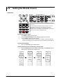
Connection via the USB Interface
Connector and Signal Names
2
2
1
3
USB Interface (Option)
3
4
4
Pin No.
Signal Name
1
2
3
4
VBUS:
D–:
D+:
GND:
+5 V
–Data
+Data
Ground
5
Precautions to Be Taken When Making Connections
6
• Connect the USB cable by inserting the connector firmly into the USB connector.
• When connecting multiple devices using USB hubs, connect the WT3000 to the USB
hub that is closest to the controller.
• Do not connect or disconnect the USB cable after the power is turned ON until the
WT3000 boots up completely (until the WT3000 is ready for operation, approximately
20 to 30 s). If you do, the WT3000 may malfunction.
7
App
Index
IM 760301-17E
3-3
3.4
Setting the USB Control
Procedure
RESET
SET
DISPLAY
NUMERIC
ITEM & ELEMENT
WAVE
UPDATE
RATE
WP/q/
TIME
SINGLE
Cursor keys
OTHERS
REMOTE
U/ I / P
HOLD
LOCAL
CAL
PAGE
PAGE
SCALING
LINE FILTER
MOTOR
SET
FREQ
FILTER
HRM SET
MEASURE
SYNC SOURCE
CURSOR
NULL
FILE
PRINT
AVG
IMAGE SAVE
STORE
MENU
STORE SET
MISC
HELP
ITEM
FORM
USER
ELEMENT
LOWER ITEM
LOWER FORM
USER SET
ALL
INTEG
START
STOP
SHIFT
To exit the menu during operation, press ESC located above
the soft keys.
In the procedural explanation below, the phrase “press the
cursor keys” may be used. This phrase refers to the
procedures for selecting items and entering values and
character strings. For details on the procedures, see section
3.14 in the User’s Manual IM760301-01E.
MENU
Selecting USB Control
1.
Press MISC to display the Misc menu.
2.
Press the Remote Control soft key to display the Remote Ctrl menu.
3.
Press the Device soft key and select USB.
Only the communication interface selected here is enabled. The WT3000 does not
accept commands that are transmitted to other unselected communication interfaces.
4.
3-4
Press the cursor keys to set the ID value.
IM 760301-17E
3.4 Setting the USB Control
1
Explanation
You can control the WT3000 from a PC using the USB interface. YOKOGAWA’s
dedicated USB connection device driver and library software (TMCTL) must be installed
on the PC in addition to entering the settings described above.
Note
Do not change the ID value while communicating via the USB interface.
3
USB Interface (Option)
Setting the ID Value
Set the ID value of the WT3000 within the following range.
1 to 127
You can connect multiple devices to a controller using the USB interface. If multiple
devices are connected in a single USB system, the ID value is used by the controller to
identify each device. Therefore, a unique ID value must be assigned to each device
within a single system.
2
4
5
6
7
App
Index
IM 760301-17E
3-5
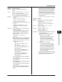
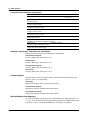
Chapter 4
4.1
Ethernet Interface (Option)
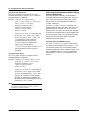
Names and Functions of Parts
1
Front Panel
2
REMOTE indicator
Turns ON when the WT3000 is in the remote mode (controlled via communications).
LOCAL key
Press this key to clear the remote mode (controlled via communications)
and enter the local mode in which key operations are enabled.
YOKOGAWA WT3000
3
PRECISION POWER ANALYZER
VOLTAGE RANGE
ELEMENT
ESC
1
2
3
4
EXT SENSOR
CURRENT RANGE
SENSOR RATIO
4
ELEMENT
ALL
COMPEN
MEASURING
RMS
WIRING
MEAN
DC
MEASURING
MODE
RMEAN
AUTO
RMS
MEAN
DC
RMEAN
MODE
AUTO
Ethernet Interface (Option)
INPUT INFO.
RESET
SET
LCD
DISPLAY
NUMERIC
ITEM & ELEMENT
WAVE
OTHERS
REMOTE
U/ I / P
UPDATE
RATE
WP/q/
TIME
SINGLE
HOLD
LOCAL
5
CAL
PAGE
PAGE
SCALING
LINE FILTER
MOTOR
SET
FREQ
FILTER
HRM SET
MEASURE
PRINT
FORM
USER
ELEMENT
LOWER FORM
USER SET
ALL
INTEG
START
STOP
SHIFT
AVG
SYNC SOURCE
CURSOR
FILE
ITEM
LOWER ITEM
NULL
IMAGE SAVE
STORE
MENU
STORE SET
MISC
HELP
6
MENU
MISC key
Press this key to configure communications.
7
Rear Panel
Ethernet port
(100BASE-TX)
Port used to connect to the controller (PC) via the network or by a
one-to-one connection. For the connection procedure, see section
5.1 in the Expansion Function User's Manual IM760301-51E.
ELEMENT
VOLTAGE
ELEMENT
1
VOLTAGE
ELEMENT
2
VOLTAGE
ELEMENT
3
VOLTAGE
4
App
Index
SERIAL
(RS-232) / USB
D/A OUTPUT
TORQUE
±
±
±
1000V MAX
1000VMAX
CURRENT
1000V MAX
1000VMAX
EXT
±
CURRENT
1000V MAX
1000VMAX
EXT
CURRENT
1000V MAX
± 20V MAX
EXT. CLK
1000VMAX
EXT
CURRENT
EXT
SPEED
GP-IB
(IEEE488)
ETHERNET
100BASE-TX
MEAS. START
± 20V MAX
42Vpk MAX
30A MAX
30A MAX
30A MAX
30A MAX
±
±
±
±
CAT II
ALL TERMINALS
1000V MAX TO
IM 760301-17E
CAT II
ALL TERMINALS
1000V MAX TO
CAT II
ALL TERMINALS
1000V MAX TO
VIDEO-OUT
(VGA)
CAT II
ALL TERMINALS
1000V MAX TO
100-240V AC
50/60Hz
200VA MAX
FUSE 250V T 6.3A
4-1
4.2
Ethernet Interface Functions and
Specifications
You can control the WT3000 from a PC using the Ethernet interface. Details about
specific functions and how to enter settings are provided below.
Receiving Function
You can specify the same settings as those specified by front panel key operations.
Receives output requests for measured and computed data, setup parameters of the
panel, and error codes.
Sending Function
Outputs measured and computed data.
Outputs panel setup parameters and the status byte.
Outputs error codes that have occurred.
Switching between Remote and Local Modes
When Switching from Local to Remote Mode
If the WT3000 receives a “:COMMunicate:REMote ON” command from the PC when it
is in the local mode, it switches to the remote mode.
• The REMOTE indicator is turned ON.
• All keys except the LOCAL key are disabled.
• Settings entered in local mode are retained even when the WT3000 switches to
remote mode.
When Switching from Remote to Local Mode
Pressing LOCAL key in remote mode puts the instrument in local mode. However, this is
void when the WT3000 has received a “:COMMunicate:LOCKout ON” command from
the PC (local lockout condition). When the WT3000 receives a
“:COMMunicate:REMote OFF” command from the PC, the WT3000 switches to the
local mode regardless of the local lockout condition.
• The REMOTE indicator is turned OFF.
• Key operations are enabled.
• Settings entered in remote mode are retained even when the WT3000 switches to
local mode.
Note
The Ethernet interface cannot be used simultaneously with other communication interfaces
(GP-IB, USB, or RS-232).
Ethernet Interface Specifications
Electrical and mechanical specifications: Conforms to IEEE 802.3.
Number of simultaneous connections:
1
Port number:
10001/tcp
For details on other specifications, see chapter 5 in the Expansion Function User’s
Manual IM760301-51E.
4-2
IM 760301-17E
4.2 Ethernet Interface Functions and Specifications
1
User Authentication Function
You must enter the user name and password to access the WT3000 from a PC using the
Ethernet interface. The user name and password for accessing the WT3000 can be
specified in the User Account screen under the Misc menu. For details, see “Setting the
Ethernet Control” in the next section.
2
Connecting the WT3000 and the PC
For the procedure of connecting the WT3000 to a PC, see section 5.1 in the Expansion
Function User’s Manual IM760301-51E.
3
4
Ethernet Interface (Option)
5
6
7
App
Index
IM 760301-17E
4-3
4.3
Setting the Ethernet Control
Procedure
RESET
SET
DISPLAY
NUMERIC
Cursor keys
ITEM & ELEMENT
WAVE
OTHERS
REMOTE
U/ I / P
UPDATE
RATE
WP/q/
TIME
SINGLE
HOLD
LOCAL
CAL
PAGE
PAGE
SCALING
LINE FILTER
MOTOR
SET
FREQ
FILTER
HRM SET
MEASURE
SYNC SOURCE
CURSOR
NULL
FILE
PRINT
AVG
IMAGE SAVE
STORE
MENU
STORE SET
MISC
HELP
ITEM
FORM
USER
ELEMENT
LOWER ITEM
LOWER FORM
USER SET
ALL
INTEG
START
STOP
SHIFT
To exit the menu during operation, press ESC located above
the soft keys.
In the procedural explanation below, the phrase “press the
cursor keys” may be used. This phrase refers to the
procedures for selecting items and entering values and
character strings. For details on the procedures, see section
3.14 in the User’s Manual IM760301-01E.
MENU
Selecting the Ethernet Control
1.
Press MISC to display the Misc menu.
2.
Press the Remote Control soft key to display the Remote Ctrl menu.
3.
Press the Device soft key and select Network.
Only the communication interface selected here is enabled. The WT3000 does not
accept commands that are transmitted to other unselected communication interfaces.
4-4
IM 760301-17E
4.3 Setting the Ethernet Control
1
Setting the User account (user name and password)
5.
Press the User Account soft key to display the User Account dialog box.
6.
Press the cursor keys to select User Name.
7.
Press SET. A keyboard appears.
8.
Use the keyboard to enter the user name.
2
For keyboard operations, see section 3.14, “Entering Values and Strings” in the User’s
Manual IM760301-01E.
9.
10.
11.
Press the cursor keys to select Password. The password setting is entered
twice.
Press SET. A keyboard appears.
Use the keyboard to enter the password.
3
•
•
4
Ethernet Interface (Option)
A password is not required if the login name is anonymous.
For keyboard operations, see section 3.14, “Entering Values and Strings” in the User’s
Manual IM760301-01E.
5
Setting the Timeout Value
12. Press the cursor keys to select Time Out.
13. Press SET. The timeout value entry box appears.
14. Press the cursor keys to set the timeout value.
15. Press SET or ESC to close the box.
6
7
App
Index
Entering TCP/IP Settings
You must enter TCP/IP settings to control the WT3000 from a PC using the Ethernet
interface. For the setup procedure, see section 5.2 in the Expansion Function User’s
Manual IM760301-51E.
Restarting the Instrument
You must restart the instrument after changing or entering a new setting for the user
account, timeout value, or TCP/IP in order for the settings to take effect.
IM 760301-17E
4-5
4.3 Setting the Ethernet Control
Explanation
You can control the WT3000 from a PC using the Ethernet interface. YOKOGAWA's
dedicated library software (TMCTL) must be installed on the PC in addition to entering
the settings described above.
Retail Software
WTViewer (760121) Version 4.01 or higher.
A trial version is available for download from the following URL.
http://www.yokogawa.com/tm/760122/
Setting the User Name
• Enter the user name to allow access to the WT3000.
• Enter up to 15 characters.
• The characters that can be used are 0-9, A-Z, %, _, ( ) (parentheses), - (minus sign).
• If you specify anonymous, the WT3000 can be accessed from the outside (PC)
without a password.
Setting the Password
• Enter the password for the user name to allow access to the WT3000.
• Enter up to 15 characters.
• The characters that can be used are 0-9, A-Z, %, _, ( ) (parentheses), - (minus sign).
• If the user name is set to anonymous, the WT3000 can be accessed from the outside
(PC) without a password.
• The password setting is entered twice.
Setting the Timeout Value
The WT3000 closes the connection to the network if there is no access for a certain
period of time (timeout time).
The available settings are 0 to 3600 s, or Infinite. The default value is Infinite.
Note
To apply new settings, the WT3000 must be power cycled.
4-6
IM 760301-17E
Chapter 5
5.1
Before Programming
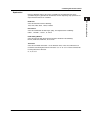
Messages
1
Program Message Unit Format
The program message unit format is shown below.
Messages and Queries
,
Messages are used to exchange information between
the controller and the instrument. Messages sent from
the controller to the WT3000 are called program
messages. Program messages that request a
response to be sent from the WT3000 to the controller
are called queries. Messages that the controller
receives from the WT3000 are called response
messages.
If a query is included in a program message, the
WT3000 sends a response message after receiving
the program message. A single response message is
always returned in response to a single program
message.
The program message format is shown below.
Space
<Program Header>
The program header indicates the command type. For
details, see page 5-3.
<Program Data>
If certain conditions are required in executing a
command, program data is added. A space (ASCII
code “20H”) separates the program data from the
header. If there are multiple sets of program data, they
are separated by commas (,).
For details, see page 5-5.
:INPut:CFACtor 3<PMT>
Example
;
<Program message unit>
Header
<PMT>
2
<Program data>
Response Message
Example
:INPut:CFACtor 3;INDependent OFF<PMT>
<RMT>
<Response Message Unit>
A response message consists of one or more
response message units; each response message unit
corresponds to one response.
Response message units are separated by a
semicolon (;).
For details regarding the format of the response
message unit, see the next section.
Example:INPUT:CFACTOR 3;INDEPENDENT 0<RMT>
Unit
Unit
Unit
<PMT>
PMT is a program message terminator. The following
three types are available.
• NL (New Line)
Same as LF (Line Feed). ASCII code “0AH.”
• ^END
The END message (EOI signal) as defined in the
IEEE488.1. (The data byte that is sent with the
END message is the last data of the program
message.)
• NL^END
NL with an END message attached. (NL is not
included in the program message.)
IM 760301-17E
5
7
;
<Response message unit>
4
6
Data
The response message format is shown below.
<Program Message Unit>
A program message consists of one or more program
message units; each unit corresponds to one
command. The instrument executes the received
commands in order.
Each program message unit is separated by a
semicolon (;).
For details regarding the format of the program
message unit, see the next section.
3
Before Programming
Program Messages
<Program header>
Unit
<RMT>
A response message terminator. It is NL^END.
5-1
App
Index
5.1 Messages
Response Message Unit Format
The response message unit format is shown below.
,
<Response header>
Space
<Response data>
<Response Header>
A response header sometimes precedes the response
data. A space separates the data from the header.
For details, see page 5-4.
<Response Data>
Response data contains the content of the response.
If there are multiple sets of response data, they are
separated by commas (,). For details, see page 5-5.
Example
100.00E-03<RMT>
Data
:DISPLAY:MODE WAVE<RMT>
Header
Data
If there are multiple queries in a program message,
responses are made in the same order as the queries.
In most cases, a single query returns a single
response message unit, but there are a few queries
that return multiple units. The first response message
unit always corresponds to the first query, but the nth
response unit may not necessarily correspond to the
nth query. Therefore, if you want to make sure that
every response is retrieved, divide the program
messages into individual messages.
• If a program message containing multiple message
units is sent, and the message contains incomplete
units, the instrument attempts to execute the ones
that are believed to be complete. However, these
attempts may not always be successful. In addition,
if the message contains queries, the responses may
not be returned.
Deadlock
The instrument can store in its buffer program and
response messages of length 1024 bytes or more (The
number of available bytes varies depending on the
operating conditions). When both the transmit and
receive buffers become full at the same time, the
instrument can no longer continue its communication
operation. This state is called a deadlock. In this
case, operation can be resumed by discarding the
program message.
Deadlock will not occur if the program message
(including the <PMT>) is kept below 1024 bytes.
Furthermore, deadlock never occurs if a program
message does not contain a query.
Precautions to Be Taken when
Transferring Messages
• If a program message that does not contain a query
is sent, the next program message can be sent at
any time.
• If a program message that contains a query is sent,
a response message must be received before the
next program message can be sent. If the next
program message is sent before the response
message is received in its entirety, an error occurs.
The response message that was not received is
discarded.
• If the controller tries to receive a response message
when there is none, an error occurs. If the
controller tries to receive a response message
before the transmission of the program message is
complete, an error occurs.
5-2
IM 760301-17E
5.2 Commands
5.2
Commands
Example
Commands
There are three types of commands (program headers)
that are sent from the controller to the instrument.
They differ in their program header formats.
Common Command Header
Commands that are defined in the IEEE 488.2-1992
are called common commands. The header format of
a common command is shown below. An asterisk (*)
is always placed in the beginning of a command.
<Mnemonic>
*
?
Common command example
*CLS
Dedicated commands used by the instrument are
classified and arranged in a hierarchy according to
their functions. The format of a compound header is
shown below. A colon (:) must be used to specify a
lower hierarchy.
When Concatenating Commands of the Same
Group
The instrument stores the hierarchical level of the
command that is currently being executed, and
performs analysis on the assumption that the next
command sent will also belong to the same level.
Therefore, common header sections can be omitted for
commands belonging to the same group.
Example :INTEGrate:MODE NORMal;
ACAL ON <PMT>
1
2
3
4
5
Before Programming
Compound Header
Group of commands related to harmonic
measurement
:INTEGrate?
:INTEGrate:MODE
:INTEGrate:ACAL
:INTEGrate:TIMer
:INTEGrate:RTIMe?
:INTEGrate:RTIMe:STARt
:INTEGrate:RTIMe:END
:INTEGrate:STARt
:INTEGrate:STOP
:INTEGrate:RESet
6
7
:
:
<Mnemonic>
Compound header example
?
:DISPlay:MODE
Simple Header
These commands are functionally independent and do
not have a hierarchy. The format of a simple header is
shown below.
:
<Mnemonic>
Simple header example
?
When Concatenating Commands of Different
Groups
If the following command does not belong to the same
group, a colon (:) is placed in front of the header.
Example :INTEGrate:MODE NORMal;:
DISPlay:MODE NUMeric<PMT>
When Concatenating Simple Headers
If a simple header follows another command, a colon
(:) is placed in front of the simple header.
Example :INTEGrate:MODE NORMal;:
HOLD ON<PMT>
:HOLD
Note
A <mnemonic> is a character string made up of alphanumeric
characters.
When Concatenating Commands
Command Group
A command group is a group of commands that have
common compound headers arranged in a hierarchy.
A command group may contain sub-groups.
When Concatenating Common Commands
Common commands that are defined in the IEEE
488.2-1992 are independent of hierarchy. Colons (:)
are not needed before a common command.
Example :INTEGrate:MODE NORMal;*CLS;
ACAL ON<PMT>
When Separating Commands with <PMT>
If a terminator is used to separate two commands,
each command is a separate message. Therefore, the
common header must be specified for each command
even when commands belonging to the same
command group are being concatenated.
Example
IM 760301-17E
:INTEGrate:MODE NORMal<PMT>:
INTEGrate:ACAL ON<PMT>
5-3
App
Index
5.2 Commands/5.3 Responses
Upper-Level Query
An upper-level query is a query in which a question
mark (?) is appended to the highest level command of
a group. Execution of an upper-level query allows all
settings that can be specified in the group to be
received at once. Some query groups which are
comprised of more than three hierarchical levels can
output all the lower level settings.
Example :INTEGrate?<PMT> ->
:INTEGRATE:MODE NORMAL;
ACAL 0;TIMER 0,0,0<RMT>
The response to an upper-level query can be
transmitted as a program message back to the
instrument. In this way, the settings that existed when
the upper-level query was made can be restored.
However, some upper-level queries do not return setup
information that is not currently in use. It is important
to remember that not all the group’s information is
necessarily returned as part of a response.
Header Interpretation Rules
The instrument interprets the header that is received
according to the rules below.
• Mnemonics are not case sensitive.
Example “CURSor” can also be written as
“cursor” or “CUrsor.”
• The lower-case section of the header can be
omitted.
Example “CURSor” can also be written as “CURSO”
or “CURS.”
• The question mark (?) at the end of a header
indicates that it is a query. The question mark (?)
cannot be omitted.
Example: The shortest abbreviation for CURSor? is
CURS?.
• If the <x> (value) at the end of a mnemonic is
omitted, it is interpreted as a 1.
Example If “ELEMent<x>” is written as “ELEM,” it
means “ELEMent1.”
• The section enclosed by braces ([]) can be omitted.
Example “[:INPut]:SCALing[:STATe][:ALL]
ON” can be written as “SCAL ON.”
However, the last section enclosed by braces ([])
cannot be omitted in an upper-level query.
Example “SCALing?” and “SCALing:STATe?” are
different queries.
5-4
5.3
Responses
When the controller sends a message unit that has a
question mark (?) in its program header (query), the
instrument returns a response message to the query.
A response message is returned in one of the following
two forms.
• Response Consisting of a Header and Data
If the response can be used as a program message
without any change, it is returned with a command
header attached.
Example :DISPlay:MODE?<PMT> ->
:DISPLAY:MODE WAVE<RMT>
• Response Consisting of Data Only
If the response cannot be used as a program
message unless changes are made to it (query-only
command), only the data section is returned.
However, there are query-only commands that
return responses with the header attached.
Example [:INPut]:POVer?<PMT> -> 0<RMT>
When You Wish to Return a Response without a
Header
Responses that return both header and data can be
set so that only the data section is returned. The
“COMMunicate:HEADer” command is used to do this.
Abbreviated Form
Normally, the lower-case section is removed from a
response header before the response is returned to
the controller. Naturally, the full form of the header can
also be used. For this, the “COMMunicate:VERBose”
command is used. The sections enclosed by braces
([]) are also omitted in the abbreviated form.
IM 760301-17E
5.4 Data
5.4
Data
Data
A data section comes after the header. A space must
be included between the header and the data. The
data contains conditions and values. Data is classified
as below.
Description
<Decimal>
A value expressed as a decimal number
(Example: VT ratio setting
-> [:INPUt]:SCALing:VT:
ELEMent1 100)
<Voltage><Current> A physical value
<Time><Frequency> (Example: Voltage range setting
->[:INPUt]:VOLTage:RANGE:
ELEMent1 100V)
Register value expressed as binary, octal,
decimal or hexadecimal.
(Example: Extended event register value
->:STATUS:EESE #HFE)
<Character Data>
Predefined character string (mnemonic). Can
be selected from { }.
(Example: Trigger mode selection
->:DISPlay:WAVE:TRIGger:
MODE {AUTO|NORMal})
<Boolean>
Indicates ON and OFF. Set using ON, OFF
or a value
(Example: Data hold ON ->:HOLD ON)
<String data>
An arbitrary character string
(Example: User-defined function
->:MEASure:FUNCtion1:
EXPRession "URMS(E1)")
<Filename>
Indicates a file name.
(Example: Save file name
->:FILE:SAVE:SETup[:EXECute]
"CASE1")
<Block data>
Arbitrary 8-bit data
(Example: Response to acquired waveform data
->#40012ABCDEFGHIJKL)
<Decimal>
<Decimal> indicates a value expressed as a decimal
number, as shown in the table below. Decimal values
are given in the NR form as specified in the ANSI
X3.42-1975.
Meaning
Integer
125
-1
Fixed-point number 125.0
-.90
Floating-point number 125.0E+0 -9E-1
Any of the forms <NR1> to <NR3> is allowed.
Example
+1000
+001.
+.1E4
• The instrument can receive decimal values that are
sent from the controller in any of the forms, <NR1>
to <NR3>. This is represented by <NRf>.
• For response messages that the instrument returns
to the controller, the form (<NR1> to <NR3> to be
used) is determined by the query. The same form is
used regardless of the size of the value.
IM 760301-17E
2
<Voltage>, <Current>, <Time>, and <Frequency>
<Voltage>, <Current>, <Time>, and <Frequency>
indicate data that have physical dimensions.
<Multiplier> or <Unit> can be attached to the <NRf>
form that was described earlier. It is expressed in one
of the following forms.
Form
Example
<NRf><Multiplier><Unit>
<NRf><Unit>
<NRf><Multiplier>
<NRf>
5MV
5E-3V
5M
5E-3
5
<Multiplier>
<Multipliers> which can be used are indicated below.
Symbol
Word
Multiplier
EX
PE
T
G
MA
K
M
U
N
P
F
Exa
Peta
Tera
Giga
Mega
Kilo
Milli
Micro
Nano
Pico
Femto
1018
1015
1012
109
106
103
10–3
10–6
10–9
10–12
10–15
Word
Meaning
V
A
S
HZ
MHZ
Volt
Ampere
Second
Hertz
Megahertz
Voltage
Current
Time
Frequency
Frequency
6
7
App
Index
<Unit>
<Units> that can be used are indicated below.
Symbol
4
Before Programming
<Register>
<NR1>
<NR2>
<NR3>
<NRf>
1
3
Data
Symbol
• For the <NR3> format, the “+” sign after the “E” can
be omitted. However, the “-” sign cannot be
omitted.
• If a value outside the setting range is entered, the
value is normalized so that it is just inside the range.
• If a value has more significant digits than the
available resolution, the value is rounded.
• <Multiplier> and <Unit> are not case sensitive.
• “U” is used to indicate micro “µ”.
• “MA” is used for Mega to distinguish it from Milli.
However, “MA” is interpreted as milliampere for
current. In addition, megahertz is expressed as
“MHZ.” Therefore, the “M (Milli)” multiplier cannot
be used for frequencies.
• If both <Multiplier> and <Unit> are omitted, the
default unit (V, A, S, or HZ) is used.
• Response messages are always expressed in the
<NR3> form. Response messages are returned
using the default unit without the <Multiplier> or
<Unit>.
5-5
5.4 Data
<Register>
<Register> indicates an integer, and can be expressed
in hexadecimal, octal, or binary as well as a decimal
number. It is used when each bit of the value has a
particular meaning. It is expressed in one of the
following forms.
Form
Example
<NRf>
1
#H<Hexadecimal value made up of the digits 0 to 9 and A to F>
#H0F
#Q<Octal value made up of the digits 0 to 7>
#Q777
#B<Binary value made up of the digits 0 and 1>
#B001100
• <Register> is not case sensitive.
• Response messages are always expressed as
<NR1>.
<Character Data>
<Character Data> is a specified string of character
data (a mnemonic). It is mainly used to indicate
options and is chosen from the character strings given
in { }. For interpretation rules, refer to “Header
Interpretation Rules” on page 5-4.
Form
Example
{AUTO|NORMal}
AUTO
• As with the header, the “COMMunicate:VERBose”
command can be used to select whether to return
the response in the full form or in the abbreviated
form.
• The “COMMunicate:HEADer” setting does not
affect the character data.
<Boolean>
<Boolean> is data that indicates ON or OFF. It is
expressed in one of the following forms.
Form
Example
{ON|OFF|<NRf>}
ON OFF 1 0
• When <Boolean> is expressed in the <NRf> form,
“OFF” is selected if the rounded integer value is 0,
and ON for all other cases.
• A response message is always returned with a 1 if
the value is ON and 0 if the value is OFF.
<String Data>
<String data> is not a specified character string like
<Character data>. It is an arbitrary character string.
The character string must be enclosed in single
quotation marks (') or double quotation marks (").
Form
Example
<String data>
'ABC' "IEEE488.2-1992"
5-6
• If a character string contains a double quotation
mark ("), the double quotation mark is replaced by
two concatenated double quotation marks ("").
This rule also applies to a single quotation mark
within a character string.
• A response message is always enclosed in double
quotation marks (").
• <String data> is an arbitrary character string.
Therefore the instrument assumes that the
remaining program message units are part of the
character string if no single (') or double quotation
mark (") is encountered. As a result, no error is
detected if a quotation mark is omitted.
<Filename>
<Filename> is data that indicates a file name. It is
expressed in one of the following forms.
Form
Example
{<NRf>|<Character data>|<String data>}
1 CASE "CASE"
• <NRf> is rounded to an 8-digit integer and
converted to ASCII code. The result is the file name
(example: 1 becomes "00000001"). Negative
values are not allowed.
• For <Character data> and <String data>, the first
eight characters become the file name.
• Response messages are always returned in the
<String data> form.
<Block Data>
<Block data> is arbitrary 8-bit data. It is only used in
response messages on the WT3000. The syntax is as
follows:
Form
Example
#N<N-digit decimal number><Data byte sequence>
#40012ABCDEFGHIJKL
• #N
Indicates that the data is <Block data>. “N”
indicates the number of succeeding data bytes
(digits) in ASCII code characters.
• <N-digit decimal number>
Indicates the number of bytes of data (example:
0012 = 12 bytes).
• <Data byte sequence>
Expresses the actual data (example:
ABCDEFGHIJKL).
• Data is comprised of 8-bit values (0 to 255). This
means that the ASCII code “0AH,” which stands for
“NL,” can also be a code used for data. Hence,
care must be taken when programming the
controller.
IM 760301-17E
5.5 Synchronization with the Controller
5.5
Synchronization with the
Controller
Overlap Commands and Sequential
Commands
IM 760301-17E
Using the *WAI Command
The *WAI command holds the subsequent commands
until the overlap command is completed.
Example :COMMunicate:OPSE
#H0040;:FILE:LOAD:SETup
“FILE1”;*WAI;:INPut:VOLTage:
RANGe:ELEMent1?<PMT>
“COMMunicate:OPSE” is a command used
to select the “*WAI” target. Here, media
access is specified.
Because “*WAI” is executed immediately
before
“:INPut:VOLTage:RANGe:ELEMent1?,”
“:INPut:VOLTage:RANGE:ELEMent1?” is
not executed until the loading of the file is
completed.
Using the COMMunicate:OVERlap command
The COMMunicate:OVERlap command enables (or
disables) overlap operation.
Example :COMMunicate:OVERlap
#HFFBF;:FILE:
LOAD:SETup
“FILE1”;:INPut:VOLTage:
RANGe:ELEMent1?<PMT>
“COMMunicate:OVERlap #HFFBF”
enables overlap operation on commands
other than media access.
Because the overlap operation of file
loading is disabled, “FILE:LOAD:SETup”
operates in the same way as a sequential
command. Therefore,
“:INPut:VOLTage:RANGe:ELEMent1?” is
not executed until the loading of the file is
completed.
5-7
1
2
3
4
5
Before Programming
There are two types of commands, overlap commands
and sequential commands. In the case of overlap
commands, the execution of the next command may
start before the execution of the previous command is
completed.
For example, if the next program message is
transmitted when specifying the voltage range and
querying the result, the response always returns the
most recent setting (100 V in this case).
:INPut:VOLTage:RANGe;ELEMent1 100V;
ELEMent?<PMT>
This is because the next command is forced to wait
until the processing of
“INPut:VOLTage:RANge:ELEMent1” itself is
completed. This type of command is called a
sequential command.
On the contrary, let us assume that you send the next
program message when you wish to load a file and
query the voltage range of the result.
:FILE:LOAD:SETup “FILE1”;:INPut:VOLTage:
RANGe:ELEMent1?
In this case, “:INPut:VOLTage:RANGe:ELEMent1?”
is executed before the loading of the file is completed,
and the voltage range that is returned is the value
before the file is loaded.
The act of executing the next command before the
processing of itself is completed such as with
“FILE:LOAD:SETup” is called an overlap operation.
A command that operates in this way is called an
overlap command.
In such case, the overlap operation can be prevented
by using the methods below.
Synchronizing with Overlap Commands
6
7
App
Index
5.5 Synchronization with the Controller
Using the *OPC Command
The *OPC command sets the OPC bit, bit 0 of the
standard event register (see page 7-5), to 1 when the
overlap operation is completed.
Example :COMMunicate:OPSE #H0040;
*ESE 1;*ESR?;*SRE 32;:FILE:LOAD:
SETup “FILE1”;*OPC<PMT>
(Read the response to *ESR?)
(Wait for a service request)
:INPut:VOLTage:RANGe:
ELEMent1?<PMT>
“COMMunicate:OPSE” is a command used
to select the “*OPC” target. Here, media
access is specified. “*ESE 1” and “*SRE
32” indicate that a service request is
generated only when the OPC bit is
1.”*ESR?” clears the standard event
register.In the example above,
“:INPut:VOLTage:RANGe:ELEMent1?” is
not executed until a service request is
generated.
Using the *OPC? Query
The *OPC? query generates a response when an
overlap operation is completed.
Example :COMMunicate:OPSE #H0040;:FILE:
LOAD:SETup “FILE1”;*OPC?<PMT>
(Read the response to *OPC?)
:INPut:VOLTage:RANGe:
ELEMent?<PMT>
Achieving Synchronization without Using
Overlap Commands
Even for sequential commands, synchronization is
sometimes required to correctly query the measured
data. If you wish to query the most recent numeric
data on every time measured data is updated, for
example, sending the
“:NUMeric[:NORMal]:VALue?” command at an
arbitrary timing can cause data that is the same as the
previous data to be received. This is because the
WT3000 returns the current measured data regardless
of whether the measured data has been updated since
the previous query.In this case, the following method
must be used to synchronize with the end of the
updating of the measured data.
Using the STATus:CONDition? query
The “STATus:CONDition?” query is used to query
the contents of the condition register (page 7-7). You
can determine whether the measured data is being
updated by reading bit 0 of the condition register. If bit
0 of the condition register is 1, the measured data is
being updated. If it is 0, the measured data can be
queried.
“COMMunicate:OPSE” is a command used
to select the “*OPC?” target. Here, media
access is specified.Because “*OPC?” does
not generate a response until the overlap
operation is completed, the loading of the
file will have been completed by the time the
response to “*OPC?” is read.
Note
Most commands are sequential commands. Overlap commands
are indicated as overlap commands in chapter 6. All other
commands are sequential commands.
5-8
IM 760301-17E
5.5 Synchronization with the Controller
Using the Extended Event Register
The changes in the condition register can be reflected
in the extended event register (page 7-7).
Example :STATus:FILTer1 FALL;:STATus:
EESE 1;EESR?;*SRE 8<PMT>
(Read the response to STATus:EESR?)
Loop
(Wait for a service request)
:NUMeric[:NORMal]:VALue?<PMT>
(Read the response to
:NUMeric[:NORMal]:VALue?)
:STATus:EESR?<PMT>
(Read the response to :STATus:EESR?)
(Return to LOOP)
IM 760301-17E
For a description of “STATus:
FILTer1 FALL” and “STATus:EESR?”
see the previous section regarding
the extended event register.
The “COMMunicate:WAIT 1” command
indicates that the program will wait for bit 0
of the extended event register to be set to
“1.”
The “:NUMeric[:NORMal]:VALue?”
command is not executed until bit 0 of the
extended event register is set to “1.”
1
2
3
4
5
Before Programming
The “STATus:FILTer1 FALL” command
sets the transition filter so that bit 0
(FILTer1) of the extended event register is
set to 1 when bit 0 of the condition register
changes from 1 to 0.
The “:STATus:EESE 1” command is used
to reflect only bit 0 of the extended event
register to the status byte.
The “STATus:EESR?” command is used to
clear the extended event register.
The “*SRE 8” command is used to
generate a service request solely on the
cause of the extended event register.
The “:NUMeric[:NORMal]:VALue?”
command is not executed until a service
request is generated.
Using the COMMunicate:WAIT command
The “COMMunicate:WAIT” command halts
communications until a specific event is generated.
Example :STATus:FILTer1 FALL;:STATus:
EESR?<PMT>
(Read the response to STATus:EESR?)
Loop
COMMunicate:WAIT 1<PMT>
:NUMeric[:NORMal]:VALue?<PMT>
(Read the response to
:NUMeric[:NORMal]:VALue?)
:STATus:EESR?<PMT>
(Read the response to :STATus:EESR?)
(Return to LOOP)
6
7
App
Index
5-9
Chapter 6
6.1
Communication Commands
1
A List of Commands
Command
ACQuisition Group
:ACQuisition?
:ACQuisition:BYTeorder
:ACQuisition:END
:ACQuisition:FORMat
:ACQuisition:HOLD
:ACQuisition:LENGth?
:ACQuisition:SEND?
:ACQuisition:SRATe?
:ACQuisition:STARt
:ACQuisition:TRACe
:AOUTput[:NORMal]:IRTime
:AOUTput[:NORMal]:MODE<x>
:AOUTput[:NORMal]:RATE<x>
2
Page
Queries all settings related to the output of the waveform sampling data.
6-17
Sets the output byte order of the waveform sampling data (FLOAT format) that
is transmitted by “:ACQuisition:SEND?” or queries the current setting.
6-17
Sets the output end point of the waveform sampling data that is transmitted
by “:ACQuisition:SEND?” or queries the current setting.
6-17
Sets the format of the waveform sampling data that is transmitted by
“:ACQuisition:SEND?” or queries the current setting.
6-17
Sets whether to hold (ON) or release (OFF) all the waveform sampling data
or queries the current setting.
6-17
Queries the total number of points of the waveform sampling data specified
by “:ACQuisition:TRACe.”
6-18
Queries the waveform sampling data specified by “:ACQuisition:TRACe.” 6-18
Queries the sampling rate of the retrieved data.
6-18
Sets the output start point of the waveform sampling data that is transmitted
by “:ACQuisition:SEND?” or queries the current setting.
6-18
Sets the target trace of “:ACQuisition:SEND?” or queries the
current setting.
6-18
Queries all settings related to the D/A output.
Queries all settings related to the D/A output.
Sets the D/A output items (function, element, and harmonic order) or
queries the current setting.
Sets the rated integration time for the D/A output of integrated values or
queries the current setting.
Sets the method of setting the rated value for the D/A output items or
queries the current setting.
Manually sets the rated maximum and minimum values for the D/A output
items or queries the current setting.
3
4
5
6
Communication Commands
AOUTput Group
:AOUTput?
:AOUTput:NORMal?
:AOUTput[:NORMal]:CHANnel<x>
Function
7
6-19
6-19
6-19
App
6-19
6-20
Index
6-20
CBCycle Group
:CBCycle?
:CBCycle:COUNt
Queries all settings related to the Cycle by Cycle measurement function.
6-21
Sets the number of cycles for Cycle by Cycle measurement or queries the
current setting.
6-21
:CBCycle:DISPlay?
Queries all settings related to the Cycle by Cycle display.
6-21
:CBCycle:DISPlay:CURSor
Sets the cursor position of the Cycle by Cycle display or queries the current
setting.
6-21
:CBCycle:DISPlay:ITEM<x>
Sets the displayed items (function and element) of the Cycle by Cycle display
or queries the current setting.
6-21
:CBCycle:DISPlay:PAGE
Sets the number of the displayed page of the Cycle by Cycle display or
queries the current setting.
6-21
:CBCycle:FILTer?
Queries all settings related to the filter for Cycle by Cycle measurement.
6-22
:CBCycle:FILTer:LINE?
Queries all settings related to the line filter for Cycle by Cycle measurement. 6-22
:CBCycle:FILTer[:LINE][:ALL]
Collectively sets the line filters of all elements for Cycle by Cycle
measurement.
6-22
:CBCycle:FILTer[:LINE]:ELEMent<x>
Sets the line filter of individual elements for Cycle by Cycle measurement or
queries the current setting.
6-22
:CBCycle:FILTer[:LINE]:MOTor
Sets the motor input line filter for Cycle by Cycle measurement or queries the
current setting.
6-22
:CBCycle:RESet
Resets Cycle by Cycle measurement.
6-22
:CBCycle:STARt
Starts Cycle by Cycle measurement.
6-22
IM 760301-17E
6-1
6.1 A List of Commands
Command
:CBCycle:STATe?
:CBCycle:SYNChronize?
:CBCycle:SYNChronize:SLOPe
:CBCycle:SYNChronize:SOURce
:CBCycle:TIMEout
:CBCycle:TRIGger?
:CBCycle:TRIGger:LEVel
:CBCycle:TRIGger:MODE
:CBCycle:TRIGger:SLOPe
:CBCycle:TRIGger:SOURce
COMMunicate Group
:COMMunicate?
:COMMunicate:HEADer
:COMMunicate:LOCKout
:COMMunicate:OPSE
:COMMunicate:OPSR?
:COMMunicate:OVERlap
:COMMunicate:REMote
:COMMunicate:STATus?
:COMMunicate:VERBose
:COMMunicate:WAIT
:COMMunicate:WAIT?
CURSor Group
:CURSor?
:CURSor:BAR?
:CURSor:BAR:POSition<x>
:CURSor:BAR[:STATe]
:CURSor:BAR:{Y<x>|DY}?
:CURSor:FFT?
:CURSor:FFT:POSition<x>
:CURSor:FFT[:STATe]
:CURSor:FFT:TRACe<x>
:CURSor:FFT:{X<x>|DX|Y<x>|DY}?
:CURSor:TRENd?
:CURSor:TRENd:POSition<x>
:CURSor:TRENd[:STATe]
:CURSor:TRENd:TRACe<x>
:CURSor:TRENd:{X<x>|Y<x>|DY}?
6-2
Function
Page
Queries the Cycle by Cycle measurement status.
6-22
Queries all settings related to the synchronization source of Cycle by Cycle
measurement.
6-22
Sets the slope of the synchronization source of Cycle by Cycle measurement
or queries the current setting.
6-22
Sets the synchronization source for Cycle by Cycle measurement or queries
the current setting.
6-23
Sets the timeout value for Cycle by Cycle measurement or queries the current
setting.
6-23
Queries all settings related to triggers.
6-23
Sets the trigger level or queries the current setting.
6-23
Sets the trigger mode or queries the current setting.
6-23
Sets the trigger slope or queries the current setting.
6-23
Sets the trigger source or queries the current setting.
6-23
Queries all settings related to communications.
Sets whether to add a header to the response to a query or queries the
current setting.
Sets or clears local lockout.
Sets the overlap command that is to be used by the *OPC, *OPC?,
and *WAI commands or queries the current setting.
Queries the operation pending status register.
Sets the commands that will operate as overlap commands or queries the
current setting.
Sets remote or local.
Queries line-specific status.
Sets the response messages to full form or abbreviated form or queries
the current setting.
Waits for a specified extended event.
Creates the response that is returned when the specified event occurs.
Queries all settings related to the cursor measurement.
Queries all settings related to the cursor measurement of the bar graph
display.
Sets the cursor position (order) on the bar graph display or queries the
current setting.
Turns ON/OFF the cursor display on the bar graph or queries the
current setting.
Queries the cursor measurement value on the bar graph display.
Queries all settings related to the cursor measurement on the FFT
waveform display.
Sets the cursor position on the FFT waveform display or queries the
current setting.
Turns ON/OFF the cursor display on the FFT waveform display or queries
the current setting.
Sets the cursor target on the FFT waveform display or queries the
current setting.
Queries the cursor measurement value on the FFT waveform display.
Queries all settings related to the cursor measurement of the trend display.
Sets the cursor position on the trend or queries the current setting.
Turns ON/OFF the cursor display on the trend display or queries the
current setting.
Sets the cursor target on the trend or queries the current setting.
Queries the cursor measurement value on the trend display.
6-24
6-24
6-24
6-24
6-24
6-24
6-24
6-25
6-25
6-25
6-25
6-26
6-26
6-26
6-26
6-26
6-26
6-26
6-27
6-27
6-27
6-27
6-27
6-27
6-27
6-27
IM 760301-17E
6.1 A List of Commands
Command
:CURSor:WAVE?
Function
Queries all settings related to the cursor measurement on the waveform
display.
:CURSor:WAVE:PATH
Sets the cursor path on the waveform display or queries the current setting.
:CURSor:WAVE:POSition<x>
Sets the cursor position on the waveform display or queries the
current setting.
:CURSor:WAVE[:STATe]
Turns ON/OFF the cursor display on the waveform display or queries the
current setting.
:CURSor:WAVE:TRACe<x>
Sets the cursor target on the waveform display or queries the current setting.
:CURSor:WAVE:{X<x>|DX|PERDt|Y<x>|DY}?
Queries the cursor measurement value on the waveform display.
DISPlay Group
:DISPlay?
:DISPlay:BAR?
:DISPlay:BAR:FORMat
:DISPlay:BAR:ITEM<x>
:DISPlay:BAR:ORDer
:DISPlay:CBCycle?
:DISPlay:CBCycle:CURSor
:DISPlay:CBCycle:ITEM<x>
:DISPlay:FFT?
:DISPlay:FFT:FFT<x>?
:DISPlay:FFT:FFT<x>:LABel
:DISPlay:FFT:FFT<x>:OBJect
:DISPlay:FFT:FFT<x>[:STATe]
:DISPlay:FFT:FORMat
:DISPlay:FFT:POINt
:DISPlay:FFT:SCOPe
:DISPlay:FFT:SPECtrum
:DISPlay:FFT:VSCale
:DISPlay:FFT:WINDow
:DISPlay:FLICker?
:DISPlay:FLICker:ELEMent
:DISPlay:FLICker:PAGE
:DISPlay:FLICker:PERiod
:DISPlay:INFOrmation?
:DISPlay:INFOrmation:PAGE
:DISPlay:INFOrmation[:STATe]
:DISPlay:MATH?
:DISPlay:MATH:CONStant<x>
:DISPlay:MATH:MATH<x>?
IM 760301-17E
6-28
6-28
2
6-28
6-28
6-28
3
6-28
4
Queries all settings related to the screen display.
6-29
Queries all settings related to the bar graph.
6-29
Sets the display format of the bar graph or queries the current setting.
6-29
Sets the bar graph item (function and element) or queries the current setting. 6-29
Sets the start and end orders of the bar graph or queries the current setting. 6-30
Queries all settings related to the Cycle by Cycle display.
6-30
Sets the cursor position of the Cycle by Cycle display or queries the current
setting.
6-30
Sets the displayed items (function and element) of the Cycle by Cycle display
or queries the current setting.
6-30
Sets the number of the displayed page of the Cycle by Cycle display or
queries the current setting.
6-30
Queries all settings related to the FFT waveform display.
6-30
Queries all settings related to the FFT waveform.
6-31
Sets the label of the FFT waveform or queries the current setting.
6-31
Sets the source waveform of the FFT computation or queries the
current setting.
6-31
Turns ON/OFF the FFT waveform display or queries the current setting.
6-31
Sets the display format of the FFT waveform or queries the current setting. 6-31
Sets the number of points of the FFT computation or queries the
current setting.
6-31
Sets the display range of the FFT waveform or queries the current setting.
6-31
Sets the display spectrum format of the FFT waveform or queries the
current setting.
6-32
Sets the display scale of the vertical axis of the FFT waveform or queries the
current setting.
6-32
Sets the window function of the FFT computation or queries the
current setting.
6-32
Queries all settings related to flicker measurement display.
6-32
Sets the element to be displayed for flicker measurement display or queries
the current setting.
6-32
Sets the number of the page to be displayed for flicker measurement display
or queries the current setting.
6-32
Sets the observation period number to be displayed for flicker measurement
display or queries the current setting.
6-32
Queries all settings related to the display of the setup parameter list.
6-32
Sets the page number of the display of setup parameter list or queries
the current setting.
6-32
Turns ON/OFF the display of the setup parameter list or queries the
current setting.
6-32
Queries all settings related to the computed waveform display.
6-33
Sets the constant to be used in the waveform computing equation or queries
the current setting.
6-33
Queries all settings related to the computed waveform.
6-33
5
6
Communication Commands
:DISPlay:CBCycle:PAGE
1
Page
7
App
Index
6-3
6.1 A List of Commands
Command
Function
Page
:DISPlay:MATH:MATH<x>:EXPRession Sets the equation of the waveform computation or queries the current setting. 6-33
:DISPlay:MATH:MATH<x>:LABel
Sets the label of the computed waveform or queries the current setting.
6-33
:DISPlay:MATH:MATH<x>:SCALing?
Queries all settings related to the scaling of the computed waveform.
6-33
:DISPlay:MATH:MATH<x>:SCALing:CENTer
Sets the center value of the manual scaling of the computed waveform or
queries the current setting.
6-34
:DISPlay:MATH:MATH<x>:SCALing:MODE
Sets the scaling mode of the computed waveform or queries the
current setting.
6-34
:DISPlay:MATH:MATH<x>:SCALing:SDIV
Sets the scale/division value of the manual scaling of the computed waveform
or queries the current setting.
6-34
:DISPlay:MATH:MATH<x>:UNIT
Sets the unit to be added to the result of the waveform computation or
queries the current setting.
6-34
:DISPlay:MODE
Sets the display format or queries the current setting.
6-35
:DISPlay:NUMeric?
Queries all settings related to the numeric display.
(The same as :DISPlay:NUMeric:NORMal?.)
6-35
:DISPlay:NUMeric:NORMal?
Queries all settings related to the numeric display.
6-35
:DISPlay:NUMeric[:NORMal]:ALL?
Queries all settings related to the numeric display (all display).
6-35
:DISPlay:NUMeric[:NORMal]:ALL:CURSor
Sets the cursor position on the numeric display (all display) or queries
the current setting.
6-35
:DISPlay:NUMeric[:NORMal]:ALL:ORDer
Sets the displayed harmonic order on the harmonic measurement function
display page of the numeric display (all display) or queries the
current setting.
6-36
:DISPlay:NUMeric[:NORMal]:ALL:PAGE
Sets the page number on the numeric display (all display) or queries the
current setting.
6-36
:DISPlay:NUMeric[:NORMal]:FORMat Sets the numeric display format or queries the current setting.
6-36
:DISPlay:NUMeric[:NORMal]:LIST? Queries all settings related to the numeric display (list display).
6-36
:DISPlay:NUMeric[:NORMal]:LIST:CURSor
Sets the cursor position on the numeric display (list display) or queries
the current setting.
6-37
:DISPlay:NUMeric[:NORMal]:LIST:HEADer
Sets the cursor position in the header section on the numeric display
(list display) or queries the current setting.
6-37
:DISPlay:NUMeric[:NORMal]:LIST:ITEM<x>
Sets the displayed items (function and element) on the numeric display
(list display) or queries the current setting.
6-37
:DISPlay:NUMeric[:NORMal]:LIST:ORDer
Sets the harmonic order cursor position of the data section on the
numeric display (list display) or queries the current setting.
6-37
:DISPlay:NUMeric[:NORMal]:{VAL4|VAL8|VAL16}?
Queries all settings related to the numeric display
({4-value|8-value|16-value} display).
6-38
:DISPlay:NUMeric[:NORMal]:{VAL4|VAL8|VAL16}:CURSor
Sets the cursor position on the numeric display
({4-value|8-value|16-value} display) or queries the current setting.
6-38
:DISPlay:NUMeric[:NORMal]:{VAL4|VAL8|VAL16}:ITEM<x>
Sets the displayed items (function, element, and harmonic order) on the
numeric display ({4-value|8-value|16-value} display) or queries the
current setting.
6-38
:DISPlay:NUMeric[:NORMal]:{VAL4|VAL8|VAL16}:PAGE
Sets the page number on the numeric display ({4-value|8-value|16-value}
display) or queries the current setting.
6-38
6-4
IM 760301-17E
6.1 A List of Commands
IM 760301-17E
1
Page
6-39
6-39
6-39
6-39
6-39
6-39
2
6-39
6-39
4
3
6-40
5
6-40
6-40
6-40
6-40
6
Communication Commands
Command
Function
:DISPlay:NUMeric[:NORMal]:{VAL4|VAL8|VAL16}:PRESet
Presets the display order pattern of displayed items on the numeric display
({4-value|8-value|16-value} display).
:DISPlay:TRENd?
Queries all settings related to the trend.
:DISPlay:TRENd:ALL
Collectively turns ON/OFF all trends.
:DISPlay:TRENd:CLEar
Clears the trend.
:DISPlay:TRENd:FORMat
Sets the display format of the trend or queries the current setting.
:DISPlay:TRENd:ITEM<x>?
Queries all settings related to the trend.
:DISPlay:TRENd:ITEM<x>[:FUNCtion]
Sets the trend item (function, element, and harmonic order) or queries the
current setting.
:DISPlay:TRENd:ITEM<x>:SCALing? Queries all settings related to the scaling of the trend.
:DISPlay:TRENd:ITEM<x>:SCALing:MODE
Sets the scaling mode of the trend or queries the current setting.
:DISPlay:TRENd:ITEM<x>:SCALing:VALue
Sets the upper and lower limits of the manual scaling of the trend or queries
the current setting.
:DISPlay:TRENd:TDIV
Sets the horizontal axis (T/div) of the trend or queries the current setting.
:DISPlay:TRENd:T<x>
Turns ON/OFF the trend or queries the current setting.
:DISPlay:VECTor?
Queries all settings related to the vector display.
:DISPlay:VECTor:NUMeric
Turns ON/OFF the numeric data display for the vector display or queries
the current setting.
:DISPlay:VECTor:OBJect
Sets the wiring unit to be displayed during vector display or queries the
current setting.
:DISPlay:VECTor:{UMAG|IMAG}
Sets the zoom factor for the vector display or queries the current setting.
:DISPlay:WAVE?
Queries all settings related to the waveform display.
:DISPlay:WAVE:ALL
Collectively turns ON/OFF all waveform displays.
:DISPlay:WAVE:FORMat
Sets the display format of the waveform or queries the current setting.
:DISPlay:WAVE:GRATicule
Sets the graticule (grid) type or queries the current setting.
:DISPlay:WAVE:INTerpolate
Sets the interpolation method of the waveform or queries the current setting.
:DISPlay:WAVE:MAPPing?
Queries all settings related to the waveform mapping to the split screen.
:DISPlay:WAVE:MAPPing[:MODE]
Sets the waveform mapping method for the split screen or queries the
current setting.
:DISPlay:WAVE:MAPPing:{U<x>|I<x>|SPEed|TORQue}
Sets the waveform mapping to the split screen or queries the current setting.
:DISPlay:WAVE:POSition?
Queries all settings related to the vertical position
(level of the center position) of the waveform.
:DISPlay:WAVE:POSition:{UALL|IALL}
Collectively sets the vertical position (level of the center position) of the
waveform {voltage|current} of all elements.
:DISPlay:WAVE:POSition:{U<x>|I<x>}
Sets the vertical position (level of the center position) of the waveform
{voltage|current} of the element or queries the current setting.
:DISPlay:WAVE:SVALue
Turns ON/OFF the scale value display or queries the current setting.
:DISPlay:WAVE:TDIV
Sets the Time/div value of the waveform or queries the current setting.
:DISPlay:WAVE:TLABel
Turns ON/OFF the waveform labels or queries the current setting.
:DISPlay:WAVE:TRIGger?
Queries all settings related to the trigger.
:DISPlay:WAVE:TRIGger:LEVel
Sets the trigger level or queries the current setting.
:DISPlay:WAVE:TRIGger:MODE
Sets the trigger mode or queries the current setting.
:DISPlay:WAVE:TRIGger:SLOPe
Sets the trigger slope or queries the current setting.
:DISPlay:WAVE:TRIGger:SOURce
Sets the trigger source or queries the current setting.
:DISPlay:WAVE:{U<x>|I<x>|SPEed|TORQue}
Turns ON/OFF the waveform display or queries the current setting.
:DISPlay:WAVE:VZoom?
Queries all settings related to the vertical zoom factor of the waveform.
:DISPlay:WAVE:VZoom:{UALL|IALL} Collectively sets the vertical zoom factor of the waveform
{voltage|current} of all elements.
6-40
7
6-40
6-41
6-41
6-41
6-41
6-41
6-41
6-41
App
Index
6-41
6-42
6-42
6-42
6-42
6-42
6-42
6-42
6-42
6-42
6-43
6-43
6-43
6-43
6-43
6-43
6-5
6.1 A List of Commands
Command
:DISPlay:WAVE:VZoom:{U<x>|I<x>}
Function
Sets the vertical zoom factor of the waveform {voltage|current} of the
element or queries the current setting.
FILE Group
:FILE?
Queries all settings related to the file operation.
:FILE:CDIRectory
Changes the current directory.
:FILE:DELete:IMAGe:{TIFF|BMP|PSCRipt|PNG|JPEG}
Deletes the screen image data file.
:FILE:DELete:NUMeric:{ASCii|FLOat}
Deletes the numeric data file.
:FILE:DELete:SETup
Deletes the setup parameter file.
:FILE:DELete:WAVE:{BINary|ASCii|FLOat}
Deletes the waveform display data file.
:FILE:DRIVe
Sets the target drive.
:FILE:FORMat:EXECute
Formats the PC card.
:FILE:FREE?
Queries the free space on the target drive.
:FILE:LOAD:ABORt
Aborts the file loading.
:FILE:LOAD:SETup
Loads the setup parameter file.
:FILE:MDIRectory
Creates a directory
:FILE:PATH?
Queries the absolute path of the current directory.
:FILE:SAVE?
Queries all settings related to the saving of files.
:FILE:SAVE:ABORt
Aborts file saving.
:FILE:SAVE:ACQuisition?
Queries all settings related to the file saving of the waveform sampling data.
:FILE:SAVE:ACQuisition[:EXECute] Saves the waveform sampling data to a file.
:FILE:SAVE:ACQuisition:TRACe
Sets the waveform sampling data to be saved to a file or queries the
current setting.
:FILE:SAVE:ACQuisition:TYPE
Sets the format of the waveform sampling data to be saved or queries the
current setting.
:FILE:SAVE:ANAMing
Sets whether to automatically name the files to be saved or queries the
current setting.
:FILE:SAVE:COMMent
Sets the comment to be added to the file to be saved or queries the
current setting.
:FILE:SAVE:NUMeric?
Queries all settings related to the saving of numeric data files.
:FILE:SAVE:NUMeric:CBCycle?
Queries all settings related to Cycle by Cycle measurement items saved to
numeric data files or queries the current setting.
:FILE:SAVE:NUMeric:CBCycle:ALL
Collectively turns ON/OFF the output of all elements and functions when
saving numeric data from Cycle by Cycle measurement to a file.
:FILE:SAVE:NUMeric:CBCycle:{ELEMent<x>|SIGMA|SIGMB}
Turns ON/OFF the output of {each element | ΣA|ΣB} when saving
numeric data from Cycle by Cycle measurement to a file.
:FILE:SAVE:NUMeric:CBCycle:<Function>
Turns ON/OFF the output of each function when saving numeric data from
Cycle by Cycle measurement to a file or queries the current setting.
:FILE:SAVE:NUMeric[:EXECute]
Saves the numeric data to a file.
:FILE:SAVE:NUMeric:NORMal?
Queries all settings related to the items saved to numeric data files.
:FILE:SAVE:NUMeric[:NORMal]:ALL Collectively turns ON/OFF the output of all element functions when saving
the numeric data to a file.
:FILE:SAVE:NUMeric[:NORMal]:{ELEMent<x>|SIGMA|SIGMB}
Turns ON/OFF the output of {each element|ΣA|ΣB} when saving the
numeric data to a file.
:FILE:SAVE:NUMeric[:NORMal]:PRESet<x>
Presets the output ON/OFF pattern of the element function for saving the
numeric data to a file.
:FILE:SAVE:NUMeric[:NORMal]:<Function>
Turns ON/OFF the output of the function when saving the numerical data to
a file or queries the current setting.
6-6
Page
6-43
6-47
6-47
6-47
6-47
6-47
6-47
6-47
6-47
6-47
6-47
6-47
6-48
6-48
6-48
6-48
6-48
6-48
6-48
6-48
6-48
6-48
6-49
6-49
6-49
6-49
6-49
6-49
6-50
6-50
6-50
6-50
6-50
IM 760301-17E
6.1 A List of Commands
Command
:FILE:SAVE:NUMeric:TYPE
:FILE:SAVE:SETup[:EXECute]
:FILE:SAVE:WAVE?
:FILE:SAVE:WAVE[:EXECute]
:FILE:SAVE:WAVE:TRACe
:FILE:SAVE:WAVE:TYPE
FLICker Group
:FLICker?
:FLICker:COUNt
:FLICker:DC?
:FLICker:DC:LIMit
:FLICker:DC[:STATe]
:FLICker:DISPlay?
:FLICker:DISPlay:ELEMent
:FLICker:DISPlay:PERiod
:FLICker:DMAX?
:FLICker:DMAX:LIMit
:FLICker:DMAX[:STATe]
:FLICker:DMIN?
:FLICker:DMIN:LIMit
:FLICker:DT?
:FLICker:DT:LIMit
:FLICker:DT[:STATe]
:FLICker:ELEMent<x>
:FLICker:FREQuency
:FLICker:INITialize
:FLICker:INTerval
:FLICker:JUDGe
:FLICker:MEASurement
:FLICker:MOVe
:FLICker:PLT?
:FLICker:PLT:LIMit
:FLICker:PLT:NVALue
:FLICker:PLT[:STATe]
:FLICker:PST?
:FLICker:PST:LIMit
IM 760301-17E
1
Page
6-50
6-50
6-50
6-51
6-51
2
3
6-51
Queries all settings related to flicker measurement.
6-52
Sets the number of measurements for the short-term flicker value Pst or
queries the current setting.
6-52
Queries all settings related to the relative steady-state voltage change dc.
6-52
Sets the limit of the relative steady-state voltage change dc or queries the
current setting.
6-52
Turns ON/OFF judgment of the relative steady-state voltage change dc or
queries the current setting.
6-52
Queries all settings related to flicker measurement display.
6-52
Sets the element to be displayed for flicker measurement display or queries
the current setting.
6-52
Sets the number of the page to be displayed for flicker measurement display
or queries the current setting.
6-53
Sets the observation period number to be displayed for flicker measurement
display or queries the current setting.
6-53
Queries all settings related to the maximum relative voltage change dmax.
6-53
Sets the limit of the maximum relative voltage change dmax or queries the
current setting.
6-53
Turns ON/OFF judgment of the maximum relative voltage change dmax or
queries the current setting.
6-53
Queries all settings related to the steady-state range dmin.
6-53
Sets the limit of steady-state range dmin or queries the current setting.
6-53
Queries all settings related to the relative voltage change time d(t).
6-53
Sets the limit of the relative voltage change time d(t) or queries the current
setting.
6-53
Turns ON/OFF judgment of the relative voltage change time d(t) or queries
the current setting.
6-53
Sets the target element of flicker measurement or queries the current setting. 6-54
Sets the target frequency of flicker measurement or queries the current
setting.
6-54
Initializes flicker measurement.
6-54
Sets the time per measurement for the short-term flicker value Pst or queries
the current setting.
6-54
Stops measurement of dmax caused by manual switching and executes
judgment.
6-54
Sets the flicker measurement method or queries the current setting.
6-54
Moves the observation period number for measurement of dmax caused by
manual switching.
6-54
Queries all settings related to the long-term flicker value Plt.
6-54
Sets the limit of the long-term flicker value Plt or queries the current setting. 6-55
Sets constant N for the equation used to compute the long-term flicker value
Plt or queries the current setting.
6-55
Turns ON/OFF judgment of the long-term flicker value Plt or queries the
current setting.
6-55
Queries all settings related to the short-term flicker value Pst.
6-55
Sets the limit for the short-term flicker value Pst or queries the current setting. 6-55
4
5
6
Communication Commands
:FLICker:DISPlay:PAGE
Function
Sets the format of the numeric data to be saved or queries the
current setting.
Executes the saving of the setup parameter file.
Queries all settings related to the saving of waveform display data files.
Saves the waveform display data to a file.
Sets the waveform to be saved to a file or queries the current setting.
Sets the format of the waveform display data to be saved or queries the
current setting.
7
App
Index
6-7
6.1 A List of Commands
Command
:FLICker:PST[:STATe]
:FLICker:RESet
:FLICker:STARt
:FLICker:STATe?
:FLICker:UN?
:FLICker:UN:MODE
:FLICker:UN:VALue
HARMonics Group
:HARMonics?
:HARMonics:FBANd
Function
Turns ON/OFF judgment of the short-term flicker value Pst or queries the
current setting.
Resets measured flicker data.
Starts flicker measurement.
Queries the status of flicker measurement.
Queries all settings related to rated voltage Un.
Sets the assignment method for rated voltage Un or queries the current
setting.
Sets the predefined rated voltage Un or queries the current setting.
Queries all settings related to harmonic measurement.
Sets the frequency bandwidth of the harmonic measurement or queries the
current setting.
:HARMonics:IEC?
Queries all settings related to IEC harmonic measurement.
:HARMonics:IEC:OBJect
Sets the IEC harmonic measurement target or queries the current setting.
:HARMonics:IEC:{UGRouping|IGRouping}
Sets the {voltage|current} grouping of the IEC harmonic measurement or
queries the current setting.
:HARMonics:ORDer
Sets the maximum and minimum orders to be measured or queries the
current setting.
:HARMonics:PLLSource
Sets the PLL source or queries the current setting.
:HARMonics:PLLWarning?
Queries all settings related to the warning messages of the PLL source.
:HARMonics:PLLWarning[:STATe]
Sets whether to generate a warning message when the PLL source is not
applied or queries the current setting.
:HARMonics:THD
Sets the equation used to compute the THD (total harmonic distortion) or
queries the current setting.
HCOPy Group
:HCOPy?
:HCOPy:ABORt
:HCOPy:AUTO?
:HCOPy:AUTO:INTerval
:HCOPy:AUTO:{STARt|END}
:HCOPy:AUTO[:STATe]
:HCOPy:AUTO:SYNChronize
:HCOPy:COMMent
:HCOPy:DIRection
:HCOPy:EXECute
:HCOPy:NETPrint?
:HCOPy:NETPrint:COLor
:HCOPy:NETPrint:FORMat
:HCOPy:PRINter?
:HCOPy:PRINter:FEED
:HCOPy:PRINter:FORMat
:HCOPy:PRINter:LIST?
:HCOPy:PRINter:LIST:INFOrmation
:HCOPy:PRINter:LIST:NORMal?
6-8
Page
6-55
6-55
6-55
6-55
6-55
6-55
6-56
6-57
6-57
6-57
6-57
6-57
6-57
6-58
6-58
6-58
6-58
Queries all settings related to printing.
6-59
Aborts printing or paper feeding.
6-59
Queries all settings related to the auto print.
6-59
Sets the auto print interval or queries the current setting.
6-59
Sets the {start|stop} reservation time of the auto print or queries the current
setting.
6-59
Turns ON/OFF the auto print or queries the current setting.
6-59
Sets the synchronization mode of the auto print or queries the current setting. 6-59
Sets the comment displayed at the bottom of the screen or queries the
current setting.
6-60
Sets the printer or queries the current setting.
6-60
Executes the print operation.
6-60
Queries all settings related to printing using a network printer.
6-60
Turns ON/OFF color printing on the network printer or queries the current
setting.
6-60
Sets the printer description language for printing on a network printer or
queries the current setting.
6-60
Queries all settings related to printing when using the built-in printer.
6-60
Executes paper feeding of the built-in printer.
6-60
Sets the contents to be printed on the built-in printer or queries the current
setting.
6-60
Queries all settings related to the printing of the numeric data list using the
built-in printer.
6-61
Sets whether to add setup parameters when printing the numeric data list
using the built-in printer or queries the current setting.
6-61
Queries all settings related to the printed items of the numeric data list
using the built-in printer.
6-61
IM 760301-17E
6.1 A List of Commands
Command
Function
:HCOPy:PRINter:LIST[:NORMal]:ALL Collectively turns ON/OFF the output of all element functions when printing
the numeric data list on the built-in printer.
:HCOPy:PRINter:LIST[:NORMal]:{ELEMent<x>|SIGMA|SIGMB}
Turns ON/OFF the output of {each element|ΣA|ΣB} when printing the
numeric data list on the built-in printer.
:HCOPy:PRINter:LIST[:NORMal]:PRESet<x>
Presets the output ON/OFF pattern of the element functions when printing
the numeric data list on the built-in printer.
:HCOPy:PRINter:LIST[:NORMal]:<Function>
Turns ON/OFF the output of the function when printing the numerical data
list using the built-in printer or queries the current setting.
HOLD Group
:HOLD
IMAGe Group
:IMAGe?
:IMAGe:ABORt
:IMAGe:COLor
:IMAGe:COMPression
:IMAGe:EXECute
:IMAGe:FORMat
:IMAGe:SAVE?
:IMAGe:SAVE:ANAMing
:IMAGe:SAVE:CDIRectory
:IMAGe:SAVE:DRIVe
:IMAGe:SAVE:NAME
:IMAGe:SEND?
INPut Group
:INPut?
[:INPut]:CFACtor
[:INPut]:CURRent?
[:INPut]:CURRent:AUTO?
[:INPut]:CURRent:AUTO[:ALL]
[:INPut]:CURRent:AUTO:ELEMent<x>
2
6-61
3
6-61
6-62
4
6-63
5
Queries all settings related to the saving of the screen image data.
Aborts the saving of the screen image data.
Sets the color tone of the screen image data to be saved or queries the
6-64
6-64
current setting.
Sets the comment displayed at the bottom of the screen or queries the
current setting.
Sets the data compression when the screen image data is in BMP format
or queries the current setting.
Saves the screen image data.
Sets the output format of the screen image data to be saved or queries the
current setting.
Queries all settings related to the saving of the screen image data.
Sets whether to automatically name the screen image data files to be saved
or queries the current setting.
Changes the save destination directory for the screen image data.
Sets the save destination drive for the screen image data.
Sets the name of the file for saving the screen image data or queries the
current setting.
Queries the screen image data.
6-64
Queries all settings related to the input element.
Sets the crest factor or queries the current setting.
Queries all settings related to the current measurement.
Queries the current auto range ON/OFF setting of all elements.
Collectively turns ON/OFF the current auto range of all elements.
Turns ON/OFF the current auto range of the element or queries the
current setting.
[:INPut]:CURRent:AUTO:{SIGMA|SIGMB}
Collectively turns ON/OFF the current auto range of all elements belonging
to wiring unit {ΣA|ΣB}.
[:INPut]:CURRent:MODE?
Queries the current mode of all elements.
[:INPut]:CURRent:MODE[:ALL]
Collectively sets the current mode of all elements.
[:INPut]:CURRent:MODE:ELEMent<x> Sets the current mode of the element or queries the current setting.
[:INPut]:CURRent:MODE:{SIGMA|SIGMB}
Collectively sets the current mode of all elements belonging to wiring unit
{ΣA|ΣB}.
[:INPut]:CURRent:RANGe?
Queries the current ranges of all elements.
[:INPut]:CURRent:RANGe[:ALL]
Collectively sets the current ranges of all elements.
IM 760301-17E
6-61
6
Communication Commands
:IMAGe:COMMent
Sets the output data (display, communications, etc.) hold or queries the
current setting.
1
Page
6-64
7
6-64
6-64
6-64
6-64
App
6-64
6-64
6-65
Index
6-65
6-65
6-66
6-66
6-66
6-66
6-66
6-67
6-67
6-67
6-67
6-67
6-67
6-67
6-67
6-9
6.1 A List of Commands
Command
Function
[:INPut]:CURRent:RANGe:ELEMent<x>
Sets the current range of the element or queries the current setting.
[:INPut]:CURRent:RANGe:{SIGMA|SIGMB}
Collectively sets the current range of all elements belonging to wiring unit
{ΣA|ΣB}.
[:INPut]:CURRent:SRATio?
Queries the current sensor scaling constants of all elements.
[:INPut]:CURRent:SRATio[:ALL]
Collectively sets the current sensor scaling constants of all elements.
[:INPut]:CURRent:SRATio:ELEMent<x>
Sets the current sensor scaling constant of the element or queries the
current setting.
[:INPut]:FILTer?
Queries all settings related to the input filter.
[:INPut]:FILTer:FREQuency?
Queries the frequency filter ON/OFF setting of all elements.
[:INPut]:FILTer:FREQuency[:ALL] Collectively turns ON/OFF the frequency filter of all elements.
[:INPut]:FILTer:FREQuency:ELEMent<x>
Turns ON/OFF the frequency filter of the element or queries the current
setting.
[:INPut]:FILTer:LINE?
Queries the line filter settings of all elements.
[:INPut]:FILTer[:LINE][:ALL]
Collectively sets the line filters of all elements.
[:INPut]:FILTer[:LINE]:ELEMent<x>
Sets the line filter of the element or queries the current setting.
[:INPut]:INDependent
Turns ON/OFF the independent setting of input elements or queries the
current setting.
[:INPut]:MODUle?
Queries the input element type.
[:INPut]:NULL
Turns ON/OFF the NULL function or queries the current setting.
[:INPut]:POVer?
Queries the peak over information.
[:INPut]:SCALing?
Queries all settings related to scaling.
[:INPut]:SCALing:{VT|CT|SFACtor}?
Queries the scaling constant of all elements.
[:INPut]:SCALing:{VT|CT|SFACtor}[:ALL]
Collectively sets the scaling constants of all elements.
[:INPut]:SCALing:{VT|CT|SFACtor}:ELEMent<x>
Sets the scaling constant of the element or queries the current setting.
[:INPut]:SCALing:STATe?
Queries the scaling ON/OFF states of all elements.
[:INPut]:SCALing[:STATe][:ALL]
Collectively turns ON/OFF the scaling of all elements.
[:INPut]:SCALing[:STATe]:ELEMent<x>
Turns ON/OFF the scaling of the element or queries the current setting.
[:INPut]:SYNChronize?
Queries the synchronization source of all elements.
[:INPut]:SYNChronize[:ALL]
Collectively sets the synchronization source of all elements.
[:INPut]:SYNChronize:ELEMent<x> Sets the synchronization source of the element or queries the current
setting.
[:INPut]:SYNChronize:{SIGMA|SIGMB}
Collectively sets the synchronization source of all elements belonging to
wiring unit {ΣA|ΣB}.
[:INPut]:VOLTage?
Queries all settings related to the voltage measurement.
[:INPut]:VOLTage:AUTO?
Queries the voltage auto range setting (ON/OFF) of all elements.
[:INPut]:VOLTage:AUTO[:ALL]
Collectively turns ON/OFF the voltage auto range of all elements.
[:INPut]:VOLTage:AUTO:ELEMent<x> Turns ON/OFF the voltage auto range of the element or queries the current
setting.
[:INPut]:VOLTage:AUTO:{SIGMA|SIGMB}
Collectively turns ON/OFF the voltage auto range of all elements belonging
to wiring unit {ΣA|ΣB}.
[:INPut]:VOLTage:MODE?
Queries the voltage mode of all elements.
[:INPut]:VOLTage:MODE[:ALL]
Collectively sets the voltage mode of all elements.
[:INPut]:VOLTage:MODE:ELEMent<x> Sets the voltage mode of the element or queries the current setting.
6-10
Page
6-68
6-68
6-69
6-69
6-69
6-69
6-69
6-69
6-69
6-69
6-69
6-69
6-69
6-70
6-70
6-70
6-70
6-70
6-70
6-70
6-70
6-70
6-71
6-71
6-71
6-71
6-71
6-71
6-71
6-71
6-71
6-71
6-72
6-72
6-72
IM 760301-17E
6.1 A List of Commands
Command
Function
[:INPut]:VOLTage:MODE:{SIGMA|SIGMB}
Collectively sets the voltage mode of all elements belonging to wiring unit
{ΣA|ΣB}.
[:INPut]:VOLTage:RANGe?
Queries the voltage range of all elements.
[:INPut]:VOLTage:RANGe[:ALL]
Collectively sets the voltage range of all elements.
[:INPut]:VOLTage:RANGe:ELEMent<x>
Sets the voltage range of the element or queries the current setting.
[:INPut]:VOLTage:RANGe:{SIGMA|SIGMB}
Collectively sets the voltage range of all elements belonging to wiring unit
{ΣA|ΣB}.
[:INPut]:WIRing
Sets the wiring system or queries the current setting.
INTEGrate Group
:INTEGrate?
:INTEGrate:ACAL
:INTEGrate:MODE
:INTEGrate:RESet
:INTEGrate:RTIMe?
:INTEGrate:RTIMe:{STARt|END}
MEASure Group
:MEASure?
:MEASure:AVERaging?
:MEASure:AVERaging:COUNt
:MEASure:AVERaging[:STATe]
:MEASure:AVERaging:TYPE
:MEASure:COMPensation?
:MEASure:COMPensation:EFFiciency
:MEASure:COMPensation:V3A3
Queries all settings related to the computation.
Queries all settings related to averaging.
Sets the averaging coefficient or queries the current setting.
Turns ON/OFF averaging or queries the current setting.
Sets the averaging type or queries the current setting.
Queries all settings related to the compensation computation.
Turns ON/OFF the efficiency compensation or queries the current setting.
Turns ON/OFF the compensation for the two-wattmeter method or
queries the current setting.
:MEASure:COMPensation:WIRing?
Queries all settings related to the wiring computation.
:MEASure:COMPensation:WIRing:ELEMent<x>
Sets the wiring compensation of the element or queries the current setting.
:MEASure:DMeasure?
Queries all settings related to the delta computation.
:MEASure:DMeasure[:SIGMA]
Sets the delta computation mode for wiring unit ΣA or queries the
current setting.
:MEASure:DMeasure:SIGMB
Sets the delta computation mode for wiring unit ΣB or queries the
current setting.
:MEASure:EFFiciency?
Queries all settings related to the efficiency computation.
:MEASure:EFFiciency:ETA<x>
Sets the efficiency equation or queries the current setting.
:MEASure:EFFiciency:UDEF<x>
Sets the user-defined parameter used in the efficiency equation or queries
the current setting.
:MEASure:FREQuency?
Queries all settings related to frequency measurement.
:MEASure:FREQuency:ITEM<x>
Sets the frequency measurement item or queries the current setting.
:MEASure:FUNCtion<x>?
Queries all settings related to user-defined functions.
:MEASure:FUNCtion<x>:EXPRession Sets the equation of the user-defined function or queries the current setting.
:MEASure:FUNCtion<x>[:STATe]
Enables (ON) or Disables (OFF) the user-defined function or queries the
current setting.
:MEASure:FUNCtion<x>:UNIT
Sets the unit to be added to the computation result of the user-defined
function or queries the current setting.
IM 760301-17E
1
6-72
6-72
6-72
2
6-72
3
6-72
6-73
4
6-74
6-74
6-74
6-74
6-74
5
6
6-74
6-74
6-74
6-74
6-75
Communication Commands
:INTEGrate:STARt
:INTEGrate:STATe?
:INTEGrate:STOP
:INTEGrate:TIMer
Queries all settings related to the integration.
Turns ON/OFF the auto calibration or queries the current setting.
Sets the integration mode or queries the current setting.
Resets the integrated value.
Queries the integration start and stop times for real-time integration mode.
Sets the integration {start|stop} time for real-time integration mode or
queries the current setting.
Starts the integration.
Queries the integration condition.
Stops the integration.
Sets the integration timer time or queries the current setting.
Page
7
6-76
6-76
6-76
6-76
6-77
6-77
6-77
App
Index
6-77
6-77
6-77
6-77
6-78
6-78
6-78
6-78
6-78
6-79
6-79
6-79
6-79
6-79
6-79
6-11
6.1 A List of Commands
Command
:MEASure:MHOLd
:MEASure:PC?
:MEASure:PC:IEC
:MEASure:PC:P<x>
:MEASure:PHASe
:MEASure:SAMPling
:MEASure:SQFormula
:MEASure:SYNChronize
MOTor Group
:MOTor?
:MOTor:FILTer?
:MOTor:FILTer[:LINE]
:MOTor:PM?
:MOTor:PM:SCALing
Function
Enables (ON) or Disables (OFF) MAX HOLD function used in the
user-defined function or queries the current setting.
Queries all settings related to the computation of Pc (Corrected Power).
Sets the equation used to compute Pc (Corrected Power) or queries the
current setting.
Sets the parameter used to compute Pc (Corrected Power) or queries the
current setting.
Sets the display format of the phase difference or queries the current setting.
Sets the sampling frequency or queries the current setting.
Sets the equation used to compute S (apparent power) and
Q (reactive power) or queries the current setting.
Sets the synchronized measurement mode or queries the current setting.
Queries all settings related to the motor evaluation function.
Queries all settings related to the input filter.
Sets the line filter or queries the current setting.
Queries all settings related to the motor output (Pm).
Sets the scaling factor used for motor output computation or queries the
current setting.
:MOTor:PM:UNIT
Sets the unit to be added to the motor output computation result or queries
the current setting.
:MOTor:POLE
Sets the motor’s number of poles or queries the current setting.
:MOTor:SPEed?
Queries all settings related to the rotating speed.
:MOTor:SPEed:AUTO
Turns ON/OFF the voltage auto range of the rotating speed signal input
(analog input format) or queries the current setting.
:MOTor:SPEed:PRANge
Sets the range of the rotating speed (pulse input format) or queries the
current setting.
:MOTor:SPEed:PULSe
Sets the pulse count of the rotating speed signal input (pulse input) or
queries the current setting.
:MOTor:SPEed:RANGe
Sets the voltage range of the rotating speed signal input (analog input
format) or queries the current setting.
:MOTor:SPEed:SCALing
Sets the scaling factor for rotating speed computation or queries the
current setting.
:MOTor:SPEed:TYPE
Sets the input type of the rotating speed signal input or queries the current
setting.
:MOTor:SPEed:UNIT
Sets the unit to be added to the rotating speed computation result or
queries the current setting.
:MOTor:SSPeed
Sets the frequency measurement source used to compute the
synchronous speed (SyncSp) or queries the current setting.
:MOTor:SYNChronize
Sets the synchronization source used to compute the rotating speed and
torque or queries the current setting.
:MOTor:TORQue?
Queries all settings related to torque.
:MOTor:TORQue:AUTO
Turns ON/OFF the voltage auto range of the torque signal input (analog
input format) or queries the current setting.
:MOTor:TORQue:PRANge
Sets the range of the torque (pulse input format) or queries the current
setting.
:MOTor:TORQue:RANGe
Sets the voltage range of the torque signal input (analog input format) or
queries the current setting.
:MOTor:TORQue:RATE?
Queries all settings related to the rated value of the torque signal (pulse
input format).
:MOTor:TORQue:RATE:{UPPer|LOWer} Sets the rated value {upper limit|lower limit} of the torque signal (pulse
input format) or queries the current setting.
:MOTor:TORQue:SCALing
Sets the scaling factor for torque computation or queries the current setting.
:MOTor:TORQue:TYPE
Sets the input type of the torque signal input or queries the current setting.
6-12
Page
6-79
6-79
6-80
6-80
6-80
6-80
6-80
6-80
6-81
6-81
6-81
6-81
6-81
6-81
6-81
6-81
6-81
6-82
6-82
6-82
6-82
6-82
6-82
6-82
6-82
6-82
6-83
6-83
6-83
6-83
6-83
6-83
6-83
IM 760301-17E
6.1 A List of Commands
Command
:MOTor:TORQue:UNIT
Function
Sets the unit to be added to the torque computation result or queries
the current setting.
Page
6-83
2
NUMeric Group
:NUMeric?
:NUMeric:CBCycle?
Queries all settings related to the numeric data output.
6-84
Queries all settings related to output of numeric list data of Cycle by Cycle
measurement.
6-84
:NUMeric:CBCycle:END
Sets the output end cycle of the numeric list data output by
“:NUMeric:CBCycle:VALue?” or queries the current setting.
6-84
:NUMeric:CBCycle:ITEM
Sets the numeric list data output items (function and element) of Cycle by
Cycle measurement or queries the current setting.
6-84
:NUMeric:CBCycle:STARt
Sets the output start cycle of the numeric list data output by
“:NUMeric:CBCycle:VALue?” or queries the current setting.
6-84
:NUMeric:CBCycle:VALue?
Queries the numeric list data from Cycle by Cycle measurement.
6-85
:NUMeric:FLICker?
Queries all settings related to output of numeric data from flicker
measurement.
6-85
:NUMeric:FLICker:COUNt?
Queries the number of the measurement within the specified observation
period at which flicker measurement stops.
6-85
:NUMeric:FLICker:FUNCtion?
Queries all settings related to output of measured flicker data
(variable format).
6-85
:NUMeric:FLICker:FUNCtion:CLEar Clears the output items of measured flicker data (variable format).
6-86
:NUMeric:FLICker:FUNCtion:DELete Deletes the output items of measured flicker data (variable format).
6-86
:NUMeric:FLICker:FUNCtion:ITEM<x>
Sets output items (function, element, and observation period) of measured
flicker data (variable format) or queries the current setting.
6-86
:NUMeric:FLICker:FUNCtion:NUMber Sets the number of measured flicker data output by
“:NUMeric:FLICker:FUNCtion:VALue?” or queries the current setting. 6-87
:NUMeric:FLICker:FUNCtion:VALue? Queries the measured flicker data (variable format).
6-87
:NUMeric:FLICker:INFOrmation?
Queries all settings related to output of flicker judgment results
(variable format).
6-87
:NUMeric:FLICker:INFOrmation:CLEar
Clears the output items of flicker judgment results (variable format).
6-88
:NUMeric:FLICker:INFOrmation:DELete
Deletes the output items of flicker judgment results (variable format).
6-88
:NUMeric:FLICker:INFOrmation:ITEM<x>
Sets output items (function, element, and observation period) of flicker
judgment results (variable format) or queries the current setting.
6-88
:NUMeric:FLICker:INFOrmation:NUMber
Sets the number of flicker judgment results output by
“:NUMeric:FLICker:INFOrmation:VALue?” or queries the current setting. 6-89
:NUMeric:FLICker:INFOrmation:VALue?
Queries the flicker judgment results (variable format).
6-89
:NUMeric:FLICker:JUDGement?
Queries the flicker judgment results (fixed format).
6-90
:NUMeric:FLICker:PERiod?
Queries the observation period number currently being measured during
flicker measurement.
6-90
:NUMeric:FLICker:VALue?
Queries the measured flicker data (fixed format).
6-91
:NUMeric:FORMat
Sets the format of the numeric data that is transmitted by
“:NUMeric[:NORMal]:VALue?” or “:NUMeric:LIST:VALue?” or queries
the current setting.
6-91
:NUMeric:HOLD
Sets whether to hold (ON) or release (OFF) all the numeric data or queries
the current setting.
6-92
:NUMeric:LIST?
Queries all settings related to the numeric list data output of harmonic
measurement.
6-92
:NUMeric:LIST:CLEar
Clears the output items of the numeric list data of harmonic measurement.
6-92
3
4
5
6
Communication Commands
IM 760301-17E
1
7
App
Index
6-13
6.1 A List of Commands
Command
:NUMeric:LIST:DELete
:NUMeric:LIST:ITEM<x>
Page
6-93
:NUMeric[:NORMal]:PRESet
:NUMeric[:NORMal]:VALue?
Function
Deletes the output items of the numeric list data of harmonic measurement.
Sets the output items (function and element) of the numeric list data of
harmonic measurement or queries the current setting.
Sets the number of the numeric list data that is transmitted by
“:NUMeric:LIST:VALue?” or queries the current setting.
Sets the maximum output order of the numeric list data of harmonic
measurement or queries the current setting.
Presets the output item pattern of the numeric list data of harmonic
measurement.
Sets the output component of the numeric list data of harmonic
measurement or queries the current setting.
Queries the numeric list data of harmonic measurement.
Queries all settings related to the numeric data output.
Clears the output items of numeric data.
Deletes the output items of numeric data.
Sets the output items (function, element, and harmonic order) of numeric
data or queries the current setting.
Sets the number of the numeric data that is transmitted by
“:NUMeric[:NORMal]:VALue?” or queries the current setting.
Presets the output item pattern of numeric data.
Queries the numeric data.
RATE Group
:RATE
Sets the data update rate or queries the current setting.
6-102
Queries all settings related to the communication status function.
Queries the contents of the condition register.
Sets the extended event enable register or queries the current setting.
Queries the content of the extended event register and clears the register.
Queries the error code and message information (top of the error queue).
Sets the transition filter or queries the current setting.
Sets whether to store messages other than errors to the error queue
(ON/OFF) or queries the current setting.
Sets whether to attach message information to the response to the
“STATus:ERRor?” query (ON/OFF) or queries the current setting.
Executes serial polling.
6-103
6-103
6-103
6-103
6-103
6-103
Queries all settings related to store and recall.
Sets the store count or queries the current setting.
Sets the store destination or queries the current setting.
Queries all settings related to the saving of the stored data.
Sets whether to automatically name the files when saving the stored data
or queries the current setting.
Sets the comment to be added to the file when saving the stored data
or queries the current setting.
Sets the name of the file when saving the stored data or queries the
current setting.
Sets the data format when saving the stored data or queries the current
setting.
Sets the store interval or queries the current setting.
Sets the stored item or queries the current setting.
Queries all settings related to the storage memory.
Sets whether to display a confirmation message when clearing the storage
memory or queries the current setting.
6-105
6-105
6-105
6-105
:NUMeric:LIST:NUMber
:NUMeric:LIST:ORDer
:NUMeric:LIST:PRESet
:NUMeric:LIST:SELect
:NUMeric:LIST:VALue?
:NUMeric:NORMal?
:NUMeric[:NORMal]:CLEar
:NUMeric[:NORMal]:DELete
:NUMeric[:NORMal]:ITEM<x>
:NUMeric[:NORMal]:NUMber
STATus Group
:STATus?
:STATus:CONDition?
:STATus:EESE
:STATus:EESR?
:STATus:ERRor?
:STATus:FILTer<x>
:STATus:QENable
:STATus:QMESsage
:STATus:SPOLl?
STORe Group
:STORe?
:STORe:COUNt
:STORe:DIRection
:STORe:FILE?
:STORe:FILE:ANAMing
:STORe:FILE:COMMent
:STORe:FILE:NAME
:STORe:FILE:TYPE
:STORe:INTerval
:STORe:ITEM
:STORe:MEMory?
:STORe:MEMory:ALERt
6-14
6-93
6-93
6-93
6-93
6-94
6-94
6-95
6-95
6-95
6-95
6-95
6-95
6-96
6-103
6-103
6-104
6-105
6-105
6-105
6-105
6-106
6-106
6-106
6-106
IM 760301-17E
6.1 A List of Commands
Command
:STORe:MEMory:CONVert:ABORt
:STORe:MEMory:CONVert:EXECute
:STORe:MEMory:INITialize
:STORe:MODE
:STORe:NUMeric?
:STORe:NUMeric:NORMal?
:STORe:NUMeric[:NORMal]:ALL
Page
6-106
6-106
6-106
6-106
6-107
6-107
6-107
6-107
2
3
4
6-107
5
6-107
6-108
6-108
6-108
6-108
6-108
6-108
6-108
6-108
6-108
SYSTem Group
:SYSTem?
Queries all settings related to the system.
6-109
:SYSTem:CLOCk?
Queries all settings related to the date/time.
6-109
:SYSTem:CLOCk:DISPlay
Turns ON/OFF the date/time display or queries the current setting.
6-109
:SYSTem:CLOCk:SNTP?
Queries all settings related to the date/time acquired via SNTP.
6-109
:SYSTem:CLOCk:SNTP[:EXECute]
Sets the date/time via SNTP.
6-109
:SYSTem:CLOCk:SNTP:GMTTime
Sets the difference from Greenwich Mean Time or queries the current setting. 6-109
:SYSTem:CLOCk:TYPE
Sets the date/time setting method or queries the current setting.
6-109
:SYSTem:DATE
Sets the date or queries the current setting.
6-109
:SYSTem:ECLear
Clears the error message displayed on the screen.
6-109
:SYSTem:FONT
Sets the display font or queries the current setting.
6-109
:SYSTem:KLOCk
Turns ON/OFF the key lock or queries the current setting.
6-110
:SYSTem:LANGuage?
Queries all settings related to the display language.
6-110
:SYSTem:LANGuage:MENU
Sets the menu language or queries the current setting.
6-110
:SYSTem:LANGuage:MESSage
Sets the message language or queries the current setting.
6-110
:SYSTem:LCD?
Queries all settings related to the LCD monitor.
6-110
:SYSTem:LCD:BRIGhtness
Sets the brightness of the LCD monitor or queries the current setting.
6-110
:SYSTem:LCD:COLor?
Queries all settings related to the display colors of the LCD monitor.
6-110
:SYSTem:LCD:COLor:GRAPh?
Queries all settings related to the display colors of the graphic items.
6-110
:SYSTem:LCD:COLor:GRAPh:{BACKground|GRATicule|CURSor|U<x>|I<x>}
Sets the display color of the {background|graticule|cursor|voltage waveform|
current waveform} or queries the current setting.
6-110
:SYSTem:LCD:COLor:GRAPh:MODE
Sets the display color mode of the graphic items or queries the current
setting.
6-110
IM 760301-17E
1
6-15
6
Communication Commands
Function
Abort converting the stored data from the memory to the file.
Executes the converting of the stored data from the memory to the file.
Executes the initialization of the storage memory.
Sets the data storage/recall or queries the current setting.
Queries all settings related to the storing of numeric data.
Queries all settings related to the stored items of numeric data.
Collectively turns ON/OFF the output of all element functions when storing
the numeric data.
:STORe:NUMeric[:NORMal]:{ELEMent<x>|SIGMA|SIGMB}
Turns ON/OFF the output of {each element|ΣA|ΣB} when storing the
numeric data.
:STORe:NUMeric[:NORMal]:PRESet<x>
Presets the output ON/OFF pattern of the element function for storing the
numeric data.
:STORe:NUMeric[:NORMal]:<Function>
Turns ON/OFF the output of the element when storing the numeric data or
queries the current setting.
:STORe:RECall
Sets the data number to be recalled or queries the current setting.
:STORe:RTIMe?
Queries the store reservation time for real-time store mode.
:STORe:RTIMe:{STARt|END}
Sets the store {start|stop} reservation time for real-time store mode or
queries the current setting.
:STORe:SMODe
Sets the store mode or queries the current setting.
:STORe:STARt
Starts the data store operation.
:STORe:STOP
Stops the data store operation.
:STORe:WAVE?
Queries all settings related to the storing of waveform display data.
:STORe:WAVE:ALL
Collectively turns ON/OFF the output of all waveforms when storing the
waveform display data.
:STORe:WAVE:{U<x>|I<x>|SPEed|TORQue}
Turns ON/OFF the output of the waveform when storing the waveform
display data or queries the current setting.
7
App
Index
6.1 A List of Commands
Command
Function
:SYSTem:LCD:COLor:TEXT?
Queries all settings related to the display colors of the text items.
:SYSTem:LCD:COLor:TEXT:{LETTer|BACKground|BOX|SUB|SELected}
Sets the display color of the {text (Menu Fore)|menu background
(Menu Back)|selected menu (Select Box)|pop-up menu (Sub Menu)|
selected key (Selected Key)} or queries the current setting.
:SYSTem:LCD:COLor:TEXT:MODE
Sets the display color mode of the text items or queries the current setting.
:SYSTem:SLOCk
Sets whether to continue the SHIFT key ON state or queries the
current setting.
:SYSTem:TIME
Sets the time or queries the current setting.
:SYSTem:USBKeyboard
Sets the USB keyboard type or queries the current setting.
WAVeform Group
:WAVeform?
:WAVeform:BYTeorder
:WAVeform:END
:WAVeform:FORMat
:WAVeform:HOLD
:WAVeform:LENGth?
:WAVeform:SEND?
:WAVeform:SRATe?
:WAVeform:STARt
:WAVeform:TRACe
:WAVeform:TRIGger?
Common Command Group
*CAL?
*CLS
*ESE
*ESR?
*IDN?
*OPC
*OPC?
*OPT?
*PSC
*RST
*SRE
*STB?
*TRG
*TST?
*WAI
6-16
Page
6-111
6-111
6-111
6-111
6-111
6-111
Queries all settings related to the waveform display data output.
Sets the output byte order of the waveform display data (FLOAT format)
that is transmitted by “:WAVeform:SEND?” or queries the current setting.
Sets the output end point of the waveform display data that is transmitted
by “:WAVeform:SEND?” or queries the current setting.
Sets the format of the waveform display data that is transmitted by
“:WAVeform:SEND?” or queries the current setting.
Sets whether to hold (ON) or release (OFF) all the waveform display data
or queries the current setting.
Queries the total number of points of the waveform specified by
“:WAVeform:TRACe”.
Queries the waveform display data specified by “:WAVeform:TRACe”.
Queries the sample rate of the retrieved waveform.
Sets the output start point of the waveform display data that is transmitted
by “:WAVeform:SEND?” or queries the current setting.
Sets the target waveform for the commands in the WAVeform group or
queries the current setting.
Queries the trigger position of the retrieved waveform.
6-112
6-112
6-112
6-112
6-112
6-112
6-113
6-113
6-113
6-113
6-113
Executes zero calibration (zero-level compensation, same operation as
pressing CAL (SHIFT+SINGLE)) and queries the result.
Clears the standard event register, extended event register, and error queue.
Sets the standard event enable register or queries the current setting.
Queries the standard event register.
Queries the instrument model.
Sets a 1 to bit 0 (OPC bit) of the standard event register bit upon the
completion of the specified overlap command.
ASCII code “1” is returned when the specified overlap command is
completed.
Queries the installed options.
Sets whether to clear the registers at power on or queries the current setting.
Executes the initialization of settings.
Sets the service request enable register or queries the current setting.
Queries the status byte register.
Executes single measurement (the same operation as when SINGLE is
pressed).
Performs a self-test and queries the result.
Holds the subsequent command until the completion of the specified
overlap operation.
6-114
6-114
6-114
6-114
6-114
6-115
6-115
6-115
6-115
6-115
6-115
6-116
6-116
6-116
6-116
IM 760301-17E
6.2
1
ACQuisition Group
The commands in this group deal with output of the waveform sampling data (acquisition data).
There are no front panel keys that correspond to the commands in this group.
The commands in this group are valid only when the advanced computation function (/G6 option) is installed.
2
:ACQuisition?
3
Function
Syntax
Example
Queries all settings related to the output of the
waveform sampling data.
:ACQuisition?
:ACQUISITION? -> :ACQUISITION:
TRACE U1;FORMAT ASCII;START 0;
END 199999;HOLD 0
:ACQuisition:BYTeorder
Function
:ACQuisition:END
Function
Sets the output end point of the waveform
display data that is transmitted by
“:ACQuisition:SEND?” or queries the current
setting.
Syntax
:ACQuisition:END {<NRf>}
:ACQuisition:END?
<NRf> = 0 to 3999999
Example :ACQUISITION:END 199999
:ACQUISITION:END? ->
:ACQUISITION:END 199999
Description Set the point in the range up to (the total
number of data points – 1). The total number of
data points can be queried using
“:ACQuisition:LENGth?.”
IM 760301-17E
Function
Sets the format of the waveform sampling data
that is transmitted by “:ACQuisition:SEND?”
or queries the current setting.
Syntax
:ACQuisition:FORMat {ASCii|FLOat}
:ACQuisition:FORMat?
Example :ACQUISITION:FORMAT FLOAT
:ACQUISITION:FORMAT? ->
:ACQUISITION:FORMAT FLOAT
Description For the differences in the waveform sampling
data output due to the format setting, see the
description for “:ACQuisition:SEND?.”
4
5
6
:ACQuisition:HOLD
Function
Sets whether to hold (ON) or release (OFF) all
the waveform sampling data or queries the
current setting.
Syntax
:ACQuisition:HOLD {<Boolean>}
:ACQuisition:HOLD?
Example :ACQUISITION:HOLD ON
:ACQUISITION:HOLD? ->
:ACQUISITION:HOLD 1
Description • This command is valid when the
measurement mode is set to MATH or FFT.
Otherwise, an error occurs.
• When “:ACQuisition:HOLD” is turned ON,
the WT3000 stops sampling the waveform
sampling data and holds all of the waveform
sampling data at that point internally. Be sure
to set :ACQuisition:HOLD to ON before
executing “:ACQuisition:SEND?.”
• For example, if you wish to retrieve the
waveform sampling data of U1 and I1 at the
same point, do the following:
:ACQuisition:HOLD ON
:ACQuisition:TRACe U1
:ACQuisition:SEND?
(Receive the waveform sampling data of U1)
:ACQuisition:TRACe I1
:ACQuisition:SEND?
(Receive the waveform sampling data of I1)
:ACQuisition:HOLD OFF
• To retrieve new waveform sampling data, set
:ACQuisition:HOLD to OFF to resume
sampling, and then set
:ACQuisition:HOLD to ON again.
6-17
Communication Commands
Sets the output byte order of the waveform
sampling data (FLOAT format) that is
transmitted by “:ACQuisition:SEND?” or
queries the current setting.
Syntax
:ACQuisition:BYTeorder {LSBFirst|
MSBFirst}
:ACQuisition:BYTeorder?
Example :ACQUISITION:BYTEORDER LSBFIRST
:ACQUISITION:BYTEORDER? ->
:ACQUISITION:BYTEORDER LSBFIRST
Description This value is valid when
“:ACQuisition:FORMat” is set to FLOat.
:ACQuisition:FORMat
7
App
Index
6.2 ACQuisition Group
:ACQuisition:LENGth?
Queries the total number of points of the
waveform sampling specified by
“:ACQuisition:TRACe.”
Syntax
:ACQuisition:LENGth?
Example :ACQUISITION:LENGTH? -> 100000
Description • When the measurement mode is MATH, the
number of data is determined by the data
update interval (:RATE) setting.
length = rate(sec) × 200000
• When the measurement mode is FFT, the
number of data is determined by the setting
for the number of FFT computation points
(:DISPlay:FFT:POINt) as follows:
(1) When “:ACQuisition:TRACe” is
FFT<x>
length = point/2+1 = 10001 or 100001
(2) When “:ACQuisition:TRACe” is not
FFT<x>
length = point = 20000 or 200000
• In a mode other than MATH or FFT, an error
occurs since there is no acquisition data, and
0 is returned.
• This command is valid when the
measurement mode is set to MATH or FFT
and the waveform sampling data is held
inside the WT3000 (:ACQuisition:HOLD
ON). Otherwise, an error occurs, because
there is no waveform sampling data. The
output is as follows:
(1) When “ASCii” is specified
Outputs NAN.
(2) When “FLOat” is specified
Outputs #800000000.
Function
:ACQuisition:SEND?
Function
Queries the waveform sampling data specified
by “:ACQuisition:TRACe.”
Syntax
:ACQuisition:SEND?
Example
• When “:ACQuisition:FORMat” is set to
{ASCii}
:ACQUISITION:SEND? ->
<NR3>,<NR3>,...
• When “:ACQuisition:FORMat” is set to
{FLOat}
:ACQUISITION:SEND? -> #8 (number of
bytes, 8 digits)(data byte sequence)
Description • The format of the waveform sampling data
that is output varies depending on the
“:ACQuisition:FORMat” setting as follows:
(1) When “ASCii” is specified
The physical value is output in the <NR3>
format. The data of each point is delimited
by a comma.
(2) When “FLOat” is specified
The physical value is output in IEEE
single-precision floating point (4-byte)
format.
The output byte order of the data of each
point follows the order that is set using the
“:ACQuisition:BYTeorder” command.
• The WT3000 outputs the waveform sampling
data in the range specified by
“:ACQuisition:{STARt|END}.” However,
data exceeding the waveform sampling data
range, 0 to (the total number of data points –
1), is not output.
6-18
:ACQuisition:SRATe?
Function
Syntax
Example
Description
Queries the sampling rate of the retrieved data
:ACQuisition:SRATe?
:ACQUISITION:SRATE? -> 195.312E+03
This command is valid when the measurement
mode is set to MATH or FFT. Otherwise, an
error occurs (returns NAN), because there is no
waveform sampling data.
:ACQuisition:STARt
Function
Sets the output start point of the waveform
display data that is transmitted by
“:ACQuisition:SEND?” or queries the current
setting.
Syntax
:ACQuisition:STARt {<NRf>}
:ACQuisition:STARt?
<NRf> = 0 to 3999999
Example :ACQUISITION:START 0
:ACQUISITION:START? ->
:ACQUISITION:START 0
Description Set the point in the range up to (the total
number of data points – 1). The total number of
data points can be queried using
“:ACQuisition:LENGth?.”
:ACQuisition:TRACe
Function
Sets the target trace of
“:ACQuisition:SEND?” or queries the current
setting.
Syntax
:ACQuisition:TRACe {U<x>|I<x>|
SPEed|TORQue|MATH<x>|FFT<x>}
:ACQuisition:TRACe?
<x> of U<x>, I<x> = 1 to 4 (element)
<x> of MATH<x> = 1 to 2 (MATH)
<x> of FFT<x> = 1 or 2 (FFT)
Example :ACQUISITION:TRACE U1
:ACQUISITION:TRACE? ->
:ACQUISITION:TRACE U1
Description {SPEed|TORQue} are valid only on the motor
version (-MV).
IM 760301-17E
6.3
1
AOUTput Group
The commands in this group deal with the D/A output.
You can make the same settings and inquiries as when the “D/A Output Items” menu of MISC on the front panel is
used.
However, the commands in this group are valid only when the D/A output (/DA option) is installed.
:AOUTput?
Function
Syntax
Example
RATE16
RATE17
RATE18
RATE19
RATE20
IRTIME
Queries all settings related to the D/A output.
:AOUTput?
:AOUTPUT? -> Same as the response to
“:AOUTput:NORMal?”
2
3
100.0E+00,-100.0E+00;
100.0E+00,-100.0E+00;
100.0E+00,-100.0E+00;
100.0E+00,-100.0E+00;
100.0E+00,-100.0E+00;
1,0,0
4
:AOUTput:NORMal?
Function
Syntax
Example
:AOUTput[:NORMal]:CHANnel<x>
Function
Sets the D/A output items (function, element,
and harmonic order) or queries the current
setting.
Syntax
:AOUTput[:NORMal]:CHANnel<x> {NONE|
<Function>,<Element>,<Order>}
:AOUTput[:NORMal]:CHANnel<x>?
<x> = 1 to 20 (output channel)
NONE = No output item
<Function> = {U|I|P|S|Q|...}(See the
function selection list (1) of “DISPlay group” on
page 6-44.)
<Element> = {<NRf>|SIGMA|SIGMB} (<NRf>
= 1 to 4)
<Order> = {TOTal|DC|<NRf>} (<NRf> = 1 to
100)
Example :AOUTPUT:NORMAL:CHANNEL1 U,1,TOTAL
:AOUTPUT:NORMAL:CHANNEL1? ->
:AOUTPUT:NORMAL:CHANNEL1 U,1,TOTAL
Description • If <Element> is omitted, element 1 is set.
• If <Order> is omitted, TOTal is set.
• <Element> or <Order> is omitted from
response to functions that do not need them.
:AOUTput[:NORMal]:IRTime
Function
Syntax
Example
Sets the rated integration time for the D/A
output of integrated values or queries the
current setting.
:AOUTput[:NORMal]:IRTime {<NRf>,
<NRf>,<NRf>}
:AOUTput[:NORMal]:IRTime?
{<NRf>, <NRf>, <NRf>} = 0, 0, 0 to 10000, 0, 0
1st <NRf> = 0 to 10000 (hour)
2nd <NRf> = 0 to 59 (minute)
3rd <NRf> = 0 to 59 (second)
:AOUTPUT:NORMAL:IRTIME 1,0,0
:AOUTPUT:NORMAL:IRTIME? ->
:AOUTPUT:NORMAL:IRTIME 1,0,0
6-19
5
6
Communication Commands
IM 760301-17E
Queries all settings related to the D/A output.
:AOUTput:NORMal?
:AOUTPUT:NORMAL? -> :AOUTPUT:
NORMAL:CHANNEL1 U,1,TOTAL;
CHANNEL2 I,1,TOTAL;
CHANNEL3 P,1,TOTAL;
CHANNEL4 S,1,TOTAL;
CHANNEL5 Q,1,TOTAL;
CHANNEL6 LAMBDA,1,TOTAL;
CHANNEL7 PHI,1,TOTAL;CHANNEL8 FU,1;
CHANNEL9 FI,1;CHANNEL10 NONE;
CHANNEL11 NONE;CHANNEL12 NONE;
CHANNEL13 NONE;CHANNEL14 NONE;
CHANNEL15 NONE;CHANNEL16 NONE;
CHANNEL17 NONE;CHANNEL18 NONE;
CHANNEL19 NONE;CHANNEL20 NONE;
MODE1 FIXED;MODE2 FIXED;
MODE3 FIXED;MODE4 FIXED;
MODE5 FIXED;MODE6 FIXED;
MODE7 FIXED;MODE8 FIXED;
MODE9 FIXED;MODE10 FIXED;
MODE11 FIXED;MODE12 FIXED;
MODE13 FIXED;MODE14 FIXED;
MODE15 FIXED;MODE16 FIXED;
MODE17 FIXED;MODE18 FIXED;
MODE19 FIXED;MODE20 FIXED;
RATE1 100.0E+00,-100.0E+00;
RATE2 100.0E+00,-100.0E+00;
RATE3 100.0E+00,-100.0E+00;
RATE4 100.0E+00,-100.0E+00;
RATE5 100.0E+00,-100.0E+00;
RATE6 100.0E+00,-100.0E+00;
RATE7 100.0E+00,-100.0E+00;
RATE8 100.0E+00,-100.0E+00;
RATE9 100.0E+00,-100.0E+00;
RATE10 100.0E+00,-100.0E+00;
RATE11 100.0E+00,-100.0E+00;
RATE12 100.0E+00,-100.0E+00;
RATE13 100.0E+00,-100.0E+00;
RATE14 100.0E+00,-100.0E+00;
RATE15 100.0E+00,-100.0E+00;
7
App
Index
6.3 AOUTput Group
:AOUTput[:NORMal]:MODE<x>
Function
Syntax
Example
Sets the method of setting the rated value for
the D/A output items or queries the current
setting.
:AOUTput[:NORMal]:MODE<x> {FIXed|
MANual}
:AOUTput[:NORMal]:MODE<x>?
<x> = 1 to 20 (output channel)
:AOUTPUT:NORMAL:MODE1 FIXED
:AOUTPUT:NORMAL:MODE1? ->
:AOUTPUT:NORMAL:MODE1 FIXED
:AOUTput[:NORMal]:RATE<x>
Function
Manually sets the rated maximum and minimum
values for the D/A output items or queries the
current setting.
Syntax
:AOUTput[:NORMal]:MODE<x> {<NRf>,
<NRf>}
:AOUTput[:NORMal]:MODE<x>?
<x> = 1 to 20 (output channel)
<NRf> = –9.999E+30 to 9.999E+30 (rated
value)
Example :AOUTPUT:NORMAL:RATE1 100,-100
:AOUTPUT:NORMAL:RATE1? ->
:AOUTPUT:NORMAL:
RATE1 100.0E+00,-100.0E+00
Description • Set the maximum value and then the
minimum value.
• This setting is valid when the method of
setting the rated value
(:AOUTput[:NORMal]:MODE<x>) is set to
FIXed.
6-20
IM 760301-17E
6.4
1
CBCycle Group
The CBCycle group contains commands related to Cycle by Cycle measurement functions.
These commands allow you to enter and query the same settings that are available under ITEM in the “CbyC Items”
menu and under FORM in the “CbyC Form” menu on the front panel.
Note that the commands in this group are only available with the Cycle by Cycle function (/CC option).
:CBCycle?
Function
Syntax
Example
Queries all settings related to the Cycle by
Cycle measurement function.
:CBCycle?
:CBCYCLE? -> :CBCYCLE:SYNCHRONIZE:
SOURCE U1;SLOPE RISE;:CBCYCLE:
TRIGGER:MODE AUTO;SOURCE U1;
SLOPE RISE;LEVEL 0.0;:CBCYCLE:
COUNT 100;TIMEOUT 10;FILTER:LINE:
ELEMENT1 50.0E+03;
ELEMENT2 50.0E+03;
ELEMENT3 50.0E+03;ELEMENT4 50.0E+03
Function
Syntax
Example
Sets the number of cycles for Cycle by Cycle
measurement or queries the current setting.
:CBCycle:COUNt {<NRf>}
:CBCycle:COUNt?
<NRf> = 1 to 3000 (number of measured cycles)
:CBCYCLE:COUNT 100
:CBCYCLE:COUNT? ->
:CBCYCLE:COUNT 100
:CBCycle:DISPlay?
Function
Syntax
Example
Queries all settings related to the Cycle by
Cycle display.
:CBCycle:DISPlay?
:CBCYCLE:DISPLAY? ->
:CBCYCLE:DISPLAY:ITEM1 FREQ;
ITEM2 U,1;ITEM3 I,1;ITEM4 P,1;
ITEM5 S,1;CURSOR 1
:CBCycle:DISPlay:CURSor
Function
Sets the cursor position of the Cycle by Cycle
display or queries the current setting.
Syntax
:CBCycle:DISPlay:CURSor {<NRf>}
:CBCycle:DISPlay:CURSor?
<NRf> = 1 to 3000 (cursor position)
Example :CBCYCLE:DISPLAY:CURSOR 1
:CBCYCLE:DISPLAY:CURSOR? ->
:CBCYCLE:DISPLAY:CURSOR 1
Description • Specifies the cursor position by the cycle
number.
• You can make the same setting or query with
the “:DISPlay:CBCycle:CURSor”
command.
IM 760301-17E
3
:CBCycle:DISPlay:ITEM<x>
Function
Sets the displayed items (function and element)
of the Cycle by Cycle display or queries the
current setting.
Syntax
:CBCycle:DISPlay:
ITEM<x> {<Function>,<Element>}
:CBCycle:DISPlay:ITEM<x>?
<x> = 1 to 5 (item number)
<Function> = {FREQ|U|I|P|S|Q|LAMBda|
SPEed|TORQue|PM}
<Element> = {<NRf>|SIGMA|SIGMB} (<NRf>
= 1 to 4)
Example :CBCYCLE:DISPLAY:ITEM1 U,1
:CBCYCLE:DISPLAY:ITEM1? ->
:CBCYCLE:DISPLAY:ITEM1 U,1
Description • When <Function> = {FREQ|SPEed|
TORQue|PM}, <Element> need not be
specified.
<Element> is omitted from the response.
• When <Element> is omitted, Element 1 is set.
• {SPEed|TORQue|PM} is only available with
the motor version (-MV).
• You can make the same setting or query with
the “:DISPlay:CBCycle:ITEM<x>”
command.
:CBCycle:DISPlay:PAGE
Function
Sets the number of the displayed page of the
Cycle by Cycle display or queries the current
setting.
Syntax
:CBCycle:DISPlay:PAGE {<NRf>}
:CBCycle:DISPlay:PAGE?
<NRf> = 1 to 150 (page number)
Example :CBCYCLE:DISPLAY:PAGE 1
:CBCYCLE:DISPLAY:PAGE? ->
:CBCYCLE:DISPLAY:PAGE 1
Description • When a page number is set, the cursor
moves to the top of the specified page.
• You can make the same setting or query with
the “:DISPlay:CBCycle:CURSor”
command.
6-21
4
5
6
Communication Commands
:CBCycle:COUNt
2
7
App
Index
6.4 CBCycle Group
:CBCycle:FILTer?
Function
Syntax
Example
Queries all settings related to the filter for Cycle
by Cycle measurement.
:CBCycle:FILTer?
:CBCYCLE:FILTER? ->
:CBCYCLE:FILTER:LINE:
ELEMENT1 50.0E+03;
ELEMENT2 50.0E+03;
ELEMENT3 50.0E+03;ELEMENT4 50.0E+03
:CBCycle:FILTer:LINE?
Function
Syntax
Example
Queries all settings related to the line filter for
Cycle by Cycle measurement.
:CBCycle:FILTer:LINE?
:CBCYCLE:FILTER:LINE? ->
:CBCYCLE:FILTER:LINE:
ELEMENT1 50.0E+03;
ELEMENT2 50.0E+03;
ELEMENT3 50.0E+03;ELEMENT4 50.0E+03
:CBCycle:FILTer[:LINE][:ALL]
Collectively sets the line filters of all elements
for Cycle by Cycle measurement
Syntax
:CBCycle:FILTer[:LINE][:ALL] {OFF|
<frequency>}
OFF = Line filter OFF
<frequency> = 500 Hz, 5.5 kHz, 50 kHz (line
filter ON, cutoff frequency)
Example :CBCYCLE:FILTER:LINE:ALL 50KHZ
Description Does not set line filters for motor input.
:CBCycle:FILTer[:LINE]:MOTor
Function
Sets the motor input line filters for Cycle by
Cycle measurement or queries the current
setting
Syntax
:CBCycle:FILTer[:LINE]:MOTor {OFF|
<frequency>}
:CBCycle:FILTer[:LINE]:MOTor?
OFF = Line filter OFF
<frequency> = 100 Hz, 50 kHz (line filter ON,
cutoff frequency)
Description Available only with the motor version (-MV).
:CBCycle:RESet
Function
Syntax
Example
Resets Cycle by Cycle measurement.
:CBCycle:RESet
:CBCYCLE:RESET
:CBCycle:STARt
Function
Syntax
Example
Starts Cycle by Cycle measurement.
:CBCycle:STARt
:CBCYCLE:START
Function
:CBCycle:FILTer[:LINE]:ELEMent<x>
Function
Syntax
Example
Sets the line filter of individual elements for
Cycle by Cycle measurement or queries the
current setting
:CBCycle:FILTer[:LINE]:
ELEMent<x> {OFF|<frequency>}
:CBCycle:FILTer[:LINE]:ELEMent<x>?
<x> = 1 to 4 (element)
OFF = Line filter OFF
<frequency> = 500 Hz, 5.5 kHz, 50 kHz (line
filter ON, cutoff frequency)
:CBCYCLE:FILTER:LINE:ELEMENT1 50KHZ
:CBCYCLE:FILTER:LINE:ELEMENT1? ->
:CBCYCLE:FILTER:LINE:
ELEMENT1 50.0E+03
:CBCycle:STATe?
Function
Queries the Cycle by Cycle measurement
status.
Syntax
:CBCycle:STATe?
Example :CBCYCLE:STATE? -> RESET
Description The contents of the response are as follows:
RESet = Reset status
STARt = Measuring
COMPlete = Measurement finished and
measured results displayed
TIMEout = Timeout
ERRFreq = Measurement finished (frequency
measurement error occurred)
:CBCycle:SYNChronize?
Function
Syntax
Example
:CBCycle:SYNChronize:SLOPe
Function
Syntax
Example
6-22
Queries all settings related to the
synchronization source for Cycle by Cycle
measurement.
:CBCycle:SYNChronize?
:CBCYCLE:SYNCHRONIZE? ->
:CBCYCLE:SYNCHRONIZE:SOURCE U1;
SLOPE RISE
Sets the slope of the synchronization source of
Cycle by Cycle measurement or queries the
current setting.
:CBCycle:SYNChronize:SLOPe {RISE|
FALL}
:CBCycle:SYNChronize:SLOPe?
:CBCYCLE:SYNCHRONIZE:SLOPE RISE
:CBCYCLE:SYNCHRONIZE:SLOPE? ->
:CBCYCLE:SYNCHRONIZE:SLOPE RISE
IM 760301-17E
6.4 CBCycle Group
:CBCycle:SYNChronize:SOURce
Function
Syntax
Example
Sets the synchronization source for Cycle by
Cycle measurement or queries the current
setting.
:CBCycle:SYNChronize:SOURce {U<x>|
I<x>|EXTernal}
:CBCycle:SYNChronize:SOURce?
<x> = 1 to 4 (element)
EXTernal = External clock input (Ext Clk)
:CBCYCLE:SYNCHRONIZE:SOURCE U1
:CBCYCLE:SYNCHRONIZE:SOURCE? ->
:CBCYCLE:SYNCHRONIZE:SOURCE U1
:CBCycle:TIMEout
Function
Syntax
Example
:CBCycle:TRIGger?
Function
Queries all settings related to triggers or queries
the current setting.
Syntax
:CBCycle:TRIGger?
Example :CBCYCLE:TRIGGER? ->
:CBCYCLE:TRIGGER:MODE AUTO;
SOURCE U1;SLOPE RISE;LEVEL 0.0
Description This is the same query as with the
“:DISPlay:WAVE:TRIGger?” command.
Function
Sets the trigger slope or queries the current
setting.
Syntax
:CBCycle:TRIGger:SLOPe {RISE|FALL|
BOTH}
:CBCycle:TRIGger:SLOPe?
Example :CBCYCLE:TRIGGER:SLOPE RISE
:CBCYCLE:TRIGGER:SLOPE? ->
:CBCYCLE:TRIGGER:SLOPE RISE
Description This is the same setting or query as with the
“:DISPlay:WAVE:TRIGger:SLOPe”
command.
3
4
:CBCycle:TRIGger:SOURce
Function
Sets the trigger source or queries the current
setting.
Syntax
:CBCycle:TRIGger:SOURce {U<x>|I<x>|
EXTernal}
:CBCycle:TRIGger:SOURce?
<x> = 1 to 4 (element)
EXTernal = External trigger input (Ext Clk)
Example :CBCYCLE:TRIGGER:SOURCE U1
:CBCYCLE:TRIGGER:SOURCE? ->
:CBCYCLE:TRIGGER:SOURCE U1
Description This is the same setting or query as with the
“:DISPlay:WAVE:TRIGger:SOURce”
command.
5
6
7
App
Index
:CBCycle:TRIGger:LEVel
Function
Sets the trigger level or queries the current
setting.
Syntax
:CBCycle:TRIGger:LEVel {<NRf>}
:CBCycle:TRIGger:LEVel?
<NRf> = -100.0 to 100.0(%)
Example :CBCYCLE:TRIGGER:LEVEL 0
:CBCYCLE:TRIGGER:LEVEL? ->
:CBCYCLE:TRIGGER:LEVEL 0.0
Description This is the same setting or query as with the
“:DISPlay:WAVE:TRIGger:LEVel?”
command.
:CBCycle:TRIGger:MODE
Function
Sets the trigger mode or queries the current
setting.
Syntax
:CBCycle:TRIGger:MODE {AUTO|NORMal}
:CBCycle:TRIGger:MODE?
Example :CBCYCLE:TRIGGER:MODE AUTO
:CBCYCLE:TRIGGER:MODE? ->
:CBCYCLE:TRIGGER:MODE AUTO
Description This is the same setting or query as with the
“:DISPlay:WAVE:TRIGger:MODE” command.
IM 760301-17E
2
Communication Commands
Sets the timeout value for Cycle by Cycle
measurement or queries the current setting.
:CBCycle:TIMEout {<NRf>}
:CBCycle:TIMEout?
<NRf> = 0 to 3600 (seconds)
(0 = No timeout)
:CBCYCLE:TIMEOUT 10
:CBCYCLE:TIMEOUT? ->
:CBCYCLE:TIMEOUT 10
1
:CBCycle:TRIGger:SLOPe
6-23
6.5
COMMunicate Group
The commands in this group deal with communications. There are no front panel keys that correspond to the
commands in this group.
:COMMunicate?
Function
Syntax
Example
Queries all settings related to communications.
:COMMunicate?
:COMMUNICATE? ->
:COMMUNICATE:HEADER 1;OPSE 96;
OVERLAP 96;VERBOSE 1
:COMMunicate:HEADer
Function
Syntax
Example
Sets whether to add a header to the response to
a query (example DISPLAY:MODE NUMERIC)
or not add the header (example NUMERIC).
:COMMunicate:HEADer {<Boolean>}
:COMMunicate:HEADer?
:COMMUNICATE:HEADER ON
:COMMUNICATE:HEADER? ->
:COMMUNICATE:HEADER 1
:COMMunicate:LOCKout
Function
Syntax
Sets or clears local lockout.
:COMMunicate:LOCKout {<Boolean>}
:COMMunicate:LOCKout?
Example :COMMUNICATE:LOCKOUT ON
:COMMUNICATE:LOCKOUT? ->
:COMMUNICATE:LOCKOUT 1
Description This command is dedicated to the optional RS232, USB, or Ethernet interface. An interface
message is available for the GP-IB interface.
:COMMunicate:OPSE
(Operation Pending Status Enable
register)
Function
Sets the overlap command that is used by the
*OPC, *OPC?, and *WAI commands or queries
the current setting.
Syntax
:COMMunicate:OPSE <Register>
:COMMunicate:OPSE?
<Register> = 0 to 65535, see the command
diagram for :COMMunicate:WAIT? on page 625.
Example :COMMUNICATE:OPSE 65535
:COMMUNICATE:OPSE? ->
:COMMUNICATE:OPSE 96
Description In the above example, all bits are set to 1 to
make all overlap commands applicable.
However, bits fixed to 0 are not set to 1. Thus,
the response to the query indicates 1 for bits 5
and 6 only.
6-24
:COMMunicate:OPSR?
(Operation Pending Status Register)
Function
Queries the value of the operation pending
status register.
Syntax
:COMMunicate:OPSR?
Example :COMMUNICATE:OPSR? -> 0
Description For details on the operation pending status
register, see the figure for the
:COMMunicate:WAIT? command (page 6-25).
:COMMunicate:OVERlap
Function
Sets the commands that will operate as overlap
commands or queries the current setting.
Syntax
:COMMunicate:OVERlap <Register>
:COMMunicate:OVERlap?
<Register> = 0 to 65535, see the command
diagram for :COMMunicate:WAIT? on page 625.
Example :COMMUNICATE:OVERLAP 65535
:COMMUNICATE:OVERLAP? ->
:COMMUNICATE:OVERLAP 96
Description • In the above example, all bits are set to 1 to
make all overlap commands applicable.
However, bits fixed to 0 are not set to 1.
Thus, the response to the query indicates 1
for bits 5 and 6 only.
• For the description regarding how to
synchronize the program using
COMMunicate:OVERlap, see page 5-7.
• In the above example, bits 5 and 6 are set to
1 to make all overlap commands applicable
(see the figure for the
:COMMunicate:WAIT? command (page 625)).
:COMMunicate:REMote
Function
Syntax
Sets remote or local. ON is remote mode.
:COMMunicate:REMote {<Boolean>}
:COMMunicate:REMote?
Example :COMMUNICATE:REMOTE ON
:COMMUNICATE:REMOTE? ->
:COMMUNICATE:REMOTE 1
Description This command is dedicated to the optional RS232, USB, or Ethernet interface. An interface
message is available for the GP-IB interface.
IM 760301-17E
6.5 COMMunicate Group
1
:COMMunicate:STATus?
Function
Syntax
Example
Queries line-specific status.
:COMMunicate:STATus?
:COMMUNICATE:STATUS? ->
:COMMUNICATE:STATUS 0
Description The meaning of each status bit is as follows:
Bit
GP-IB
RS-232
0
Unrecoverable
Parity error
transmission error
1
Always 0
Framing error
2
Always 0
Break character
detected
3 or greater Always 0
Always 0
The value 0 is always returned for the optional
USB or Ethernet interface.
The status bit is set when the corresponding
cause occurs and cleared when it is read.
2
3
4
5
:COMMunicate:VERBose
Function
Example
6
Communication Commands
Syntax
Sets whether to return the response to a query
using full spelling (example
:INPUT:VOLTAGE:RANGE:ELEMENT1
1.000E+03) or using abbreviation (example
:VOLT:RANG:ELEM 1.000E+03).
:COMMunicate:VERBose {<Boolean>}
:COMMunicate:VERBose?
:COMMUNICATE:VERBOSE ON
:COMMUNICATE:VERBOSE? ->
:COMMUNICATE:VERBOSE 1
7
App
:COMMunicate:WAIT
Function
Waits for one of the specified extended events
to occur.
Syntax
:COMMunicate:WAIT <Register>
<Register> = 0 to 65535 (extended event
register, see page 7-7.)
Example :COMMUNICATE:WAIT 1
Description For the description regarding how to
synchronize the program using
COMMunicate:WAIT, see page 5-9.
Index
:COMMunicate:WAIT?
Function
Syntax
Example
Creates the response that is returned when the
specified event occurs.
:COMMunicate:WAIT? <Register>
<Register> = 0 to 65535 (extended event
register, see page 7-7.)
:COMMUNICATE:WAIT? 65535 -> 1
Operation pending status register/Overlap
enable register
15
0
14
0
13
0
12
0
11
0
10
0
9
0
8
0
7
6
5
4
0 ACS PRN 0
3
0
2
0
1
0
0
0
When bit 5 (PRN) = 1:
Built-in printer operation not complete
When bit 6 (ACS) = 1:
Access to the medium not complete.
IM 760301-17E
6-25
6.6
CURSor Group
The commands in this group deal with cursor measurements. You can make the same settings and inquiries as when
CURSOR (SHIFT+MEASURE) on the front panel is used.
:CURSor?
Function
Syntax
Example
:CURSor:BAR:{Y<x>|DY}?
Queries all settings related to the cursor
measurement.
:CURSor?
:CURSOR? -> :CURSOR:WAVE:STATE 0;
TRACE1 U1;TRACE2 I1;PATH MAX;
POSITION1 10.0E-03;
POSITION2 40.0E-03;:CURSOR:BAR:
STATE 0;POSITION1 1;POSITION2 15;:
CURSOR:TREND:STATE 0;TRACE1 1;
TRACE2 2;POSITION1 100;
POSITION2 900
:CURSor:BAR?
Function
Queries all settings related to the cursor
measurement of the bar graph display.
Syntax
:CURSor:BAR?
Example :CURSOR:BAR? -> :CURSOR:BAR:
STATE 1;POSITION1 1;POSITION2 15
Description This command is valid only on models with the
advanced computation function (/G6 option) or
the harmonic measurement function (/G5 option).
:CURSor:BAR:POSition<x>
Function
Sets the cursor position (order) on the bar graph
display or queries the current setting.
Syntax
:CURSor:BAR:POSition<x> {<NRf>}
:CURSor:BAR:POSition<x>?
<x> = 1, 2 (1 = C1 +, 2 = C2 x)
<NRf> = 0 to 100
Example :CURSOR:BAR:POSITION1 1
:CURSOR:BAR:POSITION1? ->
:CURSOR:BAR:POSITION1 1
Description This command is valid only on models with the
advanced computation function (/G6 option) or
the harmonic measurement function (/G5
option).
:CURSor:BAR[:STATe]
Function
Turns ON/OFF the cursor display on the bar
graph display or queries the current setting.
Syntax
:CURSor:BAR[:STATe] {<Boolean>}
:CURSor:BAR:STATe?
Example :CURSOR:BAR:STATE ON
:CURSOR:BAR:STATE? ->
:CURSOR:BAR:STATE 1
Description This command is valid only on models with the
advanced computation function (/G6 option) or
the harmonic measurement function (/G5
option).
6-26
Function
Queries the cursor measurement value on the
bar graph display.
Syntax
:CURSor:BAR:{Y<x>|DY}?
Y<x> = Y-axis value at the cursor position (Y1 =
Y1+, Y2+, Y3+ Y2 = Y1x, Y2x, Y3x)
DY = Y-axis value between cursors (∆Y1, ∆Y2,
and ∆Y3)
<x> = 1, 2 (1 = C1 +, 2 = C2 x)
Example :CURSOR:BAR:Y1? -> 78.628E+00
Description • This command is valid only on models with
the advanced computation function (/G6
option) or the harmonic measurement
function (/G5 option).
• When multiple bar graphs are displayed, the
cursor measurement values of each bar
graph are returned in order.
• If the cursor display is not turned ON on the
bar graph, “NAN (Not A Number)” is returned.
:CURSor:FFT?
Function
Queries all settings related to the cursor
measurement on the FFT waveform display.
Syntax
:CURSor:FFT?
Example :CURSOR:FFT? -> :CURSOR:FFT:
STATE 0;TRACE1 FFT1;TRACE2 FFT2;
POSITION1 100;POSITION2 900
Description This command is valid only on models with the
advanced computation function (/G6 option).
:CURSor:FFT:POSition<x>
Function
Sets the cursor position on the FFT waveform
display or queries the current setting.
Syntax
:CURSor:FFT:POSition<x> {<NRf>}
:CURSor:FFT:POSition<x>?
<x> = 1, 2(1 = C1 +, 2 = C2 x)
<NRf> = 0 to 1001
Example :CURSOR:FFT:POSITION1 20
:CURSOR:FFT:POSITION1? ->
:CURSOR:FFT:POSITION1 20
Description This command is valid only on models with the
advanced computation function (/G6 option).
IM 760301-17E
6.6 CURSor Group
:CURSor:FFT[:STATe]
Function
Turns ON/OFF the cursor display on the FFT
waveform display or queries the current setting.
Syntax
:CURSor:FFT[:STATe] {<Boolean>}
:CURSor:FFT:STATe?
Example :CURSOR:FFT:STATE OFF
:CURSOR:FFT:STATE? ->
:CURSOR:FFT:STATE 0
Description This command is valid only on models with the
advanced computation function (/G6 option).
:CURSor:FFT:TRACe<x>
Function
Function
Syntax
Example
:CURSor:TRENd[:STATe]
Function
Syntax
Example
Function
Syntax
Function
:CURSor:TRENd?
Function
Syntax
Example
IM 760301-17E
Queries all settings related to the cursor
measurement of the trend display.
:CURSor:TRENd?
:CURSOR:TREND? -> :CURSOR:TREND:
STATE 1;TRACE1 1;TRACE2 2;
POSITION1 100;POSITION2 900
Turns ON/OFF the cursor display on the trend
display or queries the current setting.
:CURSor:TRENd[:STATe] {<Boolean>}
:CURSor:TRENd:STATe?
:CURSOR:TREND:STATE ON
:CURSOR:TREND:STATE? ->
:CURSOR:TREND:STATE 1
Example
2
3
4
5
6
:CURSor:TRENd:TRACe<x>
:CURSor:FFT:{X<x>|DX|Y<x>|DY}?
Queries the cursor measurement value on the
FFT waveform display.
Syntax
:CURSor:FFT:{X<x>|DX|Y<x>|DY}?
X<x> = X-axis value of the cursor position (X1 =
X+, X2 = Xx)
DX = X-axis value between cursors (∆X)
Y<x> = Y-axis value of the cursor position (Y1 =
Y+, Y2 = Yx)
DY = Y-axis value between cursors (∆Y)
<x> = 1, 2(1 = C1 +, 2 = C2 x)
Example :CURSOR:FFT:Y1? -> 78.628E+00
Description • This command is valid only on models with
the advanced computation function (/G6
option).
• If the cursor display is not turned ON in the
FFT waveform display, “NAN (Not A
Number)” is returned.
Sets the cursor position on the trend display or
queries the current setting.
:CURSor:TRENd:POSition<x> {<NRf>}
:CURSor:TRENd:POSition<x>?
<x> = 1, 2 (1 = C1 +, 2 = C2 x)
<NRf> = 0 to 1001
:CURSOR:TREND:POSITION1 10
:CURSOR:TREND:POSITION1? ->
:CURSOR:TREND:POSITION1 10
Sets the cursor target on the trend display or
queries the current setting.
:CURSor:TRENd:TRACe<x> {<NRf>}
:CURSor:TRENd:TRACe<x>?
<x> = 1, 2 (1 = C1 +, 2 = C2 x)
<NRf> = 1 to 16 (T1 to T16)
:CURSOR:TREND:TRACE1 1
:CURSOR:TREND:TRACE1? ->
:CURSOR:TREND:TRACE1 1
:CURSor:TRENd:{X<x>|Y<x>|DY}?
Function
Queries the cursor measurement value on the
trend display.
Syntax
:CURSor:TRENd:{X<x>|Y<x>|DY}?
X<x> = Trend time string of the cursor position
(X1 = D+, X2 = Dx)
Y<x> = Y-axis value of the cursor position (Y1 =
Y+, Y2 = Yx)
DY = Y-axis value between cursors (∆Y)
<x> = 1, 2 (1 = C1 +, 2 = C2 x)
Example :CURSOR:TREND:X1? ->
"2005/01/01 12:34:56"
:CURSOR:TREND:Y1? -> 78.628E+00
Description If the cursor display is not turned ON on the
trend, the following results.
For X<x>: “****/**/** **:**:**” is returned.
For Y<x> and DY: “NAN (Not A Number)” is
returned.
6-27
Communication Commands
Sets the cursor target on the FFT waveform
display or queries the current setting.
Syntax
:CURSor:FFT:TRACe<x> {FFT<x>}
:CURSor:FFT:TRACe<x>?
<x> of TRACe<x> = 1 or 2 (1 = C1 +, 2 = C2 x)
<x> of FFT<x> = 1 or 2 (FFT)
Example :CURSOR:FFT:TRACE1 FFT1
:CURSOR:FFT:TRACE1? ->
:CURSOR:FFT:TRACE1 FFT1
Description This command is valid only on models with the
advanced computation function (/G6 option).
1
:CURSor:TRENd:POSition<x>
7
App
Index
6.6 CURSor Group
:CURSor:WAVE?
Function
Syntax
Example
Queries all settings related to the cursor
measurement on the waveform display.
:CURSor:WAVE?
:CURSOR:WAVE? -> :CURSOR:WAVE:
STATE 1;TRACE1 U1;TRACE2 I1;
PATH MAX;POSITION1 10.0E-03;
POSITION2 40.0E-03
:CURSor:WAVE:PATH
Function
Syntax
Example
Sets the cursor path on the waveform display or
queries the current setting.
:CURSor:WAVE:PATH {MAX|MIN|MID}
:CURSor:WAVE:PATH?
:CURSOR:WAVE:PATH MAX
:CURSOR:WAVE:PATH? ->
:CURSOR:WAVE:PATH MAX
:CURSor:WAVE:TRACe<x>
Function
Sets the cursor target on the waveform display
or queries the current setting.
Syntax
:CURSor:WAVE:TRACe<x> {U<x>|I<x>|
SPEed|TORQue|MATH<x>}
:CURSor:WAVE:TRACe<x>?
<x> of TRACe<x> = 1 or 2 (1 = C1 +, 2 = C2 x)
<x> of U<x>, I<x> = 1 to 4
<x> of MATH<x> = 1 to 2 (MATH)
Example :CURSOR:WAVE:TRACE1 U1
:CURSOR:WAVE:TRACE1? ->
:CURSOR:WAVE:TRACE1 U1
Description • {SPEed|TORQue} are valid only on the
motor version (-MV).
• MATH<x> is valid only on models with the
advanced computation function (/G6 option).
:CURSor:WAVE:{X<x>|DX|PERDt|Y<x>|DY}?
:CURSor:WAVE:POSition<x>
Function
Sets the cursor position on the waveform
display or queries the current setting.
Syntax
:CURSor:WAVE:POSition<x> {<Time>}
:CURSor:WAVE:POSition<x>?
<x> = 1, 2 (1 = C1 +, 2 = C2 x)
<Time> = 0 to 20.00 s
Example :CURSOR:WAVE:POSITION1 10MS
:CURSOR:WAVE:POSITION1? ->
:CURSOR:WAVE:POSITION1 10.0E-03
Description The selectable range and resolution of <Time>
is determined by the Time/div value of the
waveform (:DISPlay:WAVE:TDIV).
:CURSor:WAVE[:STATe]
Function
Syntax
Example
6-28
Turns ON/OFF the cursor display on the
waveform display or queries the current setting.
:CURSor:WAVE[:STATe] {<Boolean>}
:CURSor:WAVE:STATe?
:CURSOR:WAVE:STATE ON
:CURSOR:WAVE:STATE? ->
:CURSOR:WAVE:STATE 1
Function
Queries the cursor measurement value on the
waveform display.
Syntax
:CURSor:WAVE:{X<x>|DX|PERDt|Y<x>|
DY}?
X<x> = X-axis value of the cursor position (X1 =
X+, X2 = Xx)
DX = X-axis value between cursors (∆X)
PERDt = 1/DT (1/∆X) value between cursors
Y<x> = Y-axis value of the cursor position (Y1 =
Y+, Y2 = Yx)
DY = Y-axis value between cursors (∆Y)
<x> = 1, 2 (1 = C1 +, 2 = C2 x)
Example :CURSOR:WAVE:Y1? -> 78.628E+00
Description If the cursor display is not turned ON in the
waveform display, “NAN (Not A Number)” is
returned.
IM 760301-17E
6.7
1
DISPlay Group
The commands in this group deal with the screen display.
You can make the same settings and inquiries as when the keys in the DISPLAY area and the ITEM & ELEMENT
area on the front panel are used.
:DISPlay?
Function
:DISPlay:BAR:FORMat
Function
Sets the display format of the bar graph or
queries the current setting.
Syntax
:DISPlay:BAR:FORMat {SINGle|DUAL|
TRIad}
:DISPlay:BAR:FORMat?
Example :DISPLAY:BAR:FORMAT SINGLE
:DISPLAY:BAR:FORMAT? ->
:DISPLAY:BAR:FORMAT SINGLE
Description This command is valid only on models with the
advanced computation function (/G6 option) or
the harmonic measurement function (/G5
option).
:DISPlay:BAR:ITEM<x>
Function
Sets the bar graph item (function and element)
or queries the current setting.
Syntax
:DISPlay:BAR:ITEM<x> {<Function>,
<Element>}
:DISPlay:BAR:ITEM<x>?
<x> = 1 to 3 (item number)
<Function> = {U|I|P|S|Q|LAMBda|...}
(See the function selection list (2) on page 646.)
<Element> = 1 to 4
Example :DISPLAY:BAR:ITEM1 U,1
:DISPLAY:BAR:ITEM1? ->
:DISPLAY:BAR:ITEM1 U,1
Description This command is valid only on models with the
advanced computation function (/G6 option) or
the harmonic measurement function (/G5
option).
:DISPlay:BAR?
Function
Syntax
Example
Queries all settings related to the bar graph.
:DISPlay:BAR?
:DISPLAY:BAR? -> :DISPLAY:BAR:
FORMAT SINGLE;ITEM1 U,1;ITEM2 I,1;
ITEM3 P,1;ORDER 1,100
Description This command is valid only on models with the
advanced computation function (/G6 option) or
the harmonic measurement function (/G5
option).
IM 760301-17E
6-29
3
4
5
6
Communication Commands
Queries all settings related to the screen
display.
Syntax
:DISPlay?
Example
• Example when the display mode
(:DISPlay:MODE) is “NUMeric (numeric
display)”
:DISPLAY? -> :DISPLAY:MODE
NUMERIC; (Response to
“:DISPlay:NUMeric?” with the first
“:DISPLAY:” section
removed);:DISPLAY:INFORMATION:
STATE 0;
PAGE 1
• Example when the display mode
(:DISPlay:MODE) is “WAVE (waveform
display)”
:DISPLAY? -> :DISPLAY:MODE WAVE;
(Response to “:DISPlay:WAVE?” with the
first “:DISPLAY:” section
removed);:DISPLAY:INFORMATION:
STATE 0;
PAGE 1
• Example when the display mode
(:DISPlay:MODE) is “NWAVe”
:DISPLAY? -> :DISPLAY:MODE NWAVE;
(Response to “:DISPlay:NUMeric?” with
the first “:DISPLAY:” section
removed);(same as the response to
“:DISPlay:WAVE?”);:DISPLAY:
INFORMATION:STATE 0;PAGE 1
Description Returns all settings corresponding to the display
mode (:DISPlay:MODE).
2
7
App
Index
6.7 DISPlay Group
:DISPlay:BAR:ORDer
Function
Sets the start and end orders of the bar graph or
queries the current setting.
Syntax
:DISPlay:BAR:ORDer {<NRf>,<NRf>}
:DISPlay:BAR:ORDer?
1st <NRf> = 0 to 90 (start order to be displayed)
2nd <NRf> = 10 to 100 (end order to be
displayed)
Example :DISPLAY:BAR:ORDER 1,100
:DISPLAY:BAR:ORDER? ->
:DISPLAY:BAR:ORDER 1,100
Description • This command is valid only on models with
the advanced computation function (/G6
option) or the harmonic measurement
function (/G5 option).
• Set the start order and then the end order.
• Set the end order so that it is greater than or
equal to (start order + 10).
:DISPlay:CBCycle?
Function
Queries all settings related to the Cycle by
Cycle display.
Syntax
:DISPlay:CBCycle?
Example :DISPLAY:CBCYCLE? -> :DISPLAY:
CBCYCLE:ITEM1 FREQ;ITEM2 U,1;
ITEM3 I,1;ITEM4 P,1;ITEM5 S,1;
CURSOR 1
Description Only available with the Cycle by Cycle function
(/CC option).
:DISPlay:CBCycle:CURSor
Function
Sets the cursor position of the Cycle by Cycle
display or queries the current setting.
Syntax
:DISPlay:CBCycle:CURSor {<NRf>}
:DISPlay:CBCycle:CURSor?
<NRf> = 1 to 3000 (cursor position)
Example :DISPLAY:CBCYCLE:CURSOR 1
:DISPLAY:CBCYCLE:CURSOR? ->
:DISPLAY:CBCYCLE:CURSOR 1
Description • Only available with the Cycle by Cycle
function (/CC option).
• Specifies the cursor position by the cycle
number.
6-30
:DISPlay:CBCycle:ITEM<x>
Function
Sets the displayed items (function and element)
of the Cycle by Cycle display or queries the
current setting.
Syntax
:DISPlay:CBCycle:
ITEM<x> {<Function>,<Element>}
:DISPlay:CBCycle:ITEM<x>?
<x> = 1 to 5 (item number)
<Function> = {FREQ|U|I|P|S|Q|LAMBda|
SPEed|TORQue|PM}
<Element> = {<NRf>|SIGMA|SIGMB} (<NRf>
= 1 to 4)
Example :DISPLAY:CBCYCLE:ITEM1 U,1
:DISPLAY:CBCYCLE:ITEM1? ->
:DISPLAY:CBCYCLE:ITEM1 U,1
Description • Only available with the Cycle by Cycle
function (/CC option).
• When <Function> = {FREQ|SPEed|
TORQue|PM}, <Element> need not be
specified. <Element> is omitted from the
response.
• When <Element> is omitted, Element 1 is set.
• {SPEed|TORQue|PM} is only available with
the motor version (-MV).
:DISPlay:CBCycle:PAGE
Function
Sets the number of the displayed page of the
Cycle by Cycle display or queries the current
setting.
Syntax
:DISPlay:CBCycle:PAGE {<NRf>}
:DISPlay:CBCycle:PAGE?
<NRf> = 1 to 150 (page number)
Example :DISPLAY:CBCYCLE:PAGE 1
:DISPLAY:CBCYCLE:PAGE? ->
:DISPLAY:CBCYCLE:PAGE 1
Description • Only available with the Cycle by Cycle
function (/CC option).
• When a page number is set, the cursor
moves to the top of the specified page.
:DISPlay:FFT?
Function
Queries all settings related to the FFT waveform
display.
Syntax
:DISPlay:FFT?
Example :DISPLAY:FFT? -> :DISPLAY:FFT:
FORMAT SINGLE;POINT 20000;
WINDOW RECTANGLE;SCOPE 0,10000;
VSCALE LOG;SPECTRUM LINE;FFT1:
STATE 1;OBJECT U1;LABEL "FFT1";:
DISPLAY:FFT:FFT2:STATE 1;OBJECT I1;
LABEL "FFT2"
Description This command is valid only on models with the
advanced computation function (/G6 option).
IM 760301-17E
6.7 DISPlay Group
:DISPlay:FFT:FFT<x>?
Function
Queries all settings related to the FFT
waveform.
Syntax
:DISPlay:FFT:FFT<x>?
<x> = 1, 2 (FFT)
Example :DISPLAY:FFT:FFT1? -> :DISPLAY:FFT:
FFT1:STATE 1;OBJECT U1;LABEL "FFT1"
Description This command is valid only on models with the
advanced computation function (/G6 option).
:DISPlay:FFT:FFT<x>:LABel
Function
:DISPlay:FFT:FFT<x>:OBJect
Function
Sets the source waveform of the FFT
computation or queries the current setting.
Syntax
:DISPlay:FFT:FFT<x>:OBJect {U<x>|
I<x>|P<x>|PA|PB|Q<x>|QA|QB|SPEed|
TORQue}
:DISPlay:FFT:FFT<x>:OBJect?
<x> of FFT<x> = 1, 2 (FFT)
<x> of U<x>, I<x>, P<x>, Q<x> = 1 to 4
(element)
PA, QA = PΣA, QΣA (only on models with 2 to 4
elements)
PB, QB = PΣB, QΣB (only on models with 4
elements)
Example :DISPLAY:FFT:FFT1:OBJECT U1
:DISPLAY:FFT:FFT1:OBJECT? ->
:DISPLAY:FFT:FFT1:OBJECT U1
Description • This command is valid only on models with
the advanced computation function (/G6
option).
• {SPEed|TORQue} are valid only on the
motor version (-MV).
IM 760301-17E
Function
Turns ON/OFF the FFT waveform display or
queries the current setting.
Syntax
:DISPlay:FFT:
FFT<x>[:STATe] {<Boolean>}
:DISPlay:FFT:FFT<x>:STATe?
<x> = 1, 2 (FFT)
Example :DISPLAY:FFT:FFT1:STATE ON
:DISPLAY:FFT:FFT1:STATE? ->
:DISPLAY:FFT:FFT1:STATE 1
Description This command is valid only on models with the
advanced computation function (/G6 option).
2
3
4
:DISPlay:FFT:FORMat
Function
Sets the display format of the FFT waveform or
queries the current setting.
Syntax
:DISPlay:FFT:FORMat {SINGle|DUAL}
:DISPlay:FFT:FORMat?
Example :DISPLAY:FFT:FORMAT SINGLE
:DISPLAY:FFT:FORMAT? ->
:DISPLAY:FFT:FORMAT SINGLE
Description This command is valid only on models with the
advanced computation function (/G6 option).
5
6
Communication Commands
Sets the label of the FFT waveform or queries
the current setting.
Syntax
:DISPlay:FFT:FFT<x>:
LABel {<String>}
:DISPlay:FFT:FFT<x>:LABel?
<x> = 1, 2 (FFT)
<String> = Up to 8 characters
Example :DISPLAY:FFT:FFT1:LABEL "FFT1"
:DISPLAY:FFT:FFT1:LABEL? ->
:DISPLAY:FFT:FFT1:LABEL "FFT1"
Description This command is valid only on models with the
advanced computation function (/G6 option).
1
:DISPlay:FFT:FFT<x>[:STATe]
7
:DISPlay:FFT:POINt
Function
Sets the number of points of the FFT
computation or queries the current setting.
Syntax
:DISPlay:FFT:POINt {<NRf>}
:DISPlay:FFT:POINt?
<NRf> = 20000, 200000
Example :DISPLAY:FFT:POINT 20000
:DISPLAY:FFT:POINT? ->
:DISPLAY:FFT:POINT 20000
Description This command is valid only on models with the
advanced computation function (/G6 option).
:DISPlay:FFT:SCOPe
Function
Sets the display range of the FFT waveform or
queries the current setting.
Syntax
:DISPlay:FFT:SCOPe {<NRf>,<NRf>}
:DISPlay:FFT:SCOPe?
1st <NRf> = 0 to 99990 (display start point)
2nd <NRf> = 10 to 100000 (display end point)
Example :DISPLAY:FFT:SCOPE 0,10000
:DISPLAY:FFT:SCOPE? ->
:DISPLAY:FFT:SCOPE 0,10000
Description • This command is valid only on models with
the advanced computation function (/G6
option).
• Set the start point and then the end point.
• Set the end point so that it is greater than or
equal to (start point + 10).
6-31
App
Index
6.7 DISPlay Group
:DISPlay:FFT:SPECtrum
Function
Sets the display spectrum format of the FFT
waveform or queries the current setting.
Syntax
:DISPlay:FFT:SPECtrum {LINE|BAR}
:DISPlay:FFT:SPECtrum?
Example :DISPLAY:FFT:SPECTRUM LINE
:DISPLAY:FFT:SPECTRUM? ->
:DISPLAY:FFT:SPECTRUM LINE
Description This command is valid only on models with the
advanced computation function (/G6 option).
:DISPlay:FFT:VSCale
Sets the display scale of the vertical axis of the
FFT waveform or queries the current setting.
Syntax
:DISPlay:FFT:VSCale {LINear|LOG}
:DISPlay:FFT:VSCale?
Example :DISPLAY:FFT:VSCALE LOG
:DISPLAY:FFT:VSCALE? ->
:DISPLAY:FFT:VSCALE LOG
Description This command is valid only on models with the
advanced computation function (/G6 option).
:DISPlay:FLICker:PAGE
Function
Sets the page numbers to be displayed for
flicker measurement display or queries the
current setting.
Syntax
:DISPlay:FLICker:PAGE {<NRf>}
:DISPlay:FLICker:PAGE?
<NRf> = 1 to 9 (page number)
Example :DISPLAY:FLICKER:PAGE 1
:DISPLAY:FLICKER:PAGE? ->
:DISPLAY:FLICKER:PAGE 1
Description Only available with the flicker measurement
function (/FL option).
Function
:DISPlay:FFT:WINDow
Function
Sets the window function of the FFT
computation or queries the current setting.
Syntax
:DISPlay:FFT:WINDow {RECTangle|
HANNing|FLATtop}
:DISPlay:FFT:WINDow?
Example :DISPLAY:FFT:WINDOW RECTANGLE
:DISPLAY:FFT:WINDOW? ->
:DISPLAY:FFT:WINDOW RECTANGLE
Description This command is valid only on models with the
advanced computation function (/G6 option).
:DISPlay:FLICker:PERiod
Function
Sets the display observation period number for
flicker measurement display or queries the
current setting.
Syntax
:DISPlay:FLICker:PERiod {<NRf>}
:DISPlay:FLICker:PERiod?
<NRf> = 1 to 99 (observation period number)
Example :DISPLAY:FLICKER:PERIOD 1
:DISPLAY:FLICKER:PERIOD? ->
:DISPLAY:FLICKER:PERIOD 1
Description Only available with the flicker measurement
function (/FL option).
:DISPlay:INFOrmation?
Function
Syntax
Example
Queries all settings related to the display of the
setup parameter list.
:DISPlay:INFOrmation?
:DISPLAY:INFORMATION? ->
:DISPLAY:INFORMATION:STATE 0;PAGE 1
:DISPlay:INFOrmation:PAGE
:DISPlay:FLICker?
Queries all settings related to flicker
measurement display.
Syntax
:DISPlay:FLICker?
Example :DISPLAY:FLICKER? ->
:DISPLAY:FLICKER:ELEMENT 1;PERIOD 1
Description Only available with the flicker measurement
function (/FL option).
Function
Function
:DISPlay:FLICker:ELEMent
Function
Sets the element to be displayed for flicker
measurement display or queries the current
setting.
Syntax
:DISPlay:FLICker:ELEMent {<NRf>}
:DISPlay:FLICker:ELEMent?
<NRf> = 1 to 4 (element)
Example :DISPLAY:FLICKER:ELEMENT 1
:DISPLAY:FLICKER:ELEMENT? ->
:DISPLAY:FLICKER:ELEMENT 1
Description Only available with the flicker measurement
function (/FL option).
6-32
Syntax
Example
Sets the page number of the display of setup
parameter list or queries the current setting.
:DISPlay:INFOrmation {<NRf>}
:DISPlay:INFOrmation?
<NRf> = 1 to 4 (page number)
:DISPLAY:INFORMATION:PAGE 1
:DISPLAY:INFORMATION:PAGE? ->
:DISPLAY:INFORMATION:PAGE 1
:DISPlay:INFOrmation[:STATe]
Function
Syntax
Example
Turns ON/OFF the display of the setup
parameter list or queries the current setting.
:DISPlay:INFOrmation
[:STATe] {<Boolean>}
:DISPlay:INFOrmation:STATe?
:DISPLAY:INFORMATION:STATE ON
:DISPLAY:INFORMATION:STATE? ->
:DISPLAY:INFORMATION:STATE 1
IM 760301-17E
6.7 DISPlay Group
:DISPlay:MATH?
Function
:DISPlay:MATH:CONStant<x>
Function
Sets the constant to be used in the waveform
computing equation or queries the current
setting.
Syntax
:DISPlay:MATH:CONStant<x> {<NRf>}
:DISPlay:MATH:CONStant<x>?
<x> = 1 to 8 (K1 to K8)
<NRf> = –9.9999E+30 to 9.9999E+30
Example :DISPLAY:MATH:CONSTANT1 1.0000E+00
:DISPLAY:MATH:CONSTANT1? ->
:DISPLAY:MATH:CONSTANT1 1.0000E+00
Description This command is valid only on models with the
advanced computation function (/G6 option).
:DISPlay:MATH:MATH<x>?
Function
Queries all settings related to the computed
waveform.
Syntax
:DISPlay:MATH:MATH<x>?
<x> = 1, 2 (MATH)
Example :DISPLAY:MATH:MATH1? -> :DISPLAY:
MATH:MATH1:EXPRESSION "U1*I1";
SCALING:MODE AUTO;
CENTER 0.0000E+00;SDIV 25.000E+00;:
DISPLAY:MATH:MATH1:UNIT "W":
LABEL "Math1"
Description This command is valid only on models with the
advanced computation function (/G6 option).
IM 760301-17E
Function
Sets the equation of the waveform computation
or queries the current setting.
Syntax
:DISPlay:MATH:MATH<x>:
EXPRession {<String>}
:DISPlay:MATH:MATH<x>:EXPRession?
<x> = 1, 2 (MATH)
<String> = Up to 50 characters
Example :DISPLAY:MATH:MATH1:
EXPRESSION "U1*I1"
:DISPLAY:MATH:MATH1:EXPRESSION? ->
:DISPLAY:MATH:MATH1:
EXPRESSION "U1*I1"
Description This command is valid only on models with the
advanced computation function (/G6 option).
2
3
4
5
:DISPlay:MATH:MATH<x>:LABel
Function
Sets the label of the computed waveform or
queries the current setting.
Syntax
:DISPlay:MATH:MATH<x>:
LABel {<String>}
:DISPlay:MATH:MATH<x>:LABel?
<x> = 1, 2 (MATH)
<String> = Up to 8 characters
Example :DISPLAY:MATH:MATH1:LABEL "Math1"
:DISPLAY:MATH:MATH1:LABEL? ->
:DISPLAY:MATH:MATH1:LABEL "Math1"
Description This command is valid only on models with the
advanced computation function (/G6 option).
:DISPlay:MATH:MATH<x>:SCALing?
Function
Queries all settings related to the scaling of the
computed waveform.
Syntax
:DISPlay:MATH:MATH<x>:SCALing?
<x> = 1, 2 (MATH)
Example :DISPLAY:MATH:MATH1? ->
:DISPLAY:MATH:MATH1:SCALING:
MODE AUTO;CENTER 0.0000E+00;
SDIV 25.000E+00
Description This command is valid only on models with the
advanced computation function (/G6 option).
6-33
6
Communication Commands
Queries all settings related to the computed
waveform display.
Syntax
:DISPlay:MATH?
Example :DISPLAY:MATH? -> :DISPLAY:MATH:
MATH1:EXPRESSION "U1*I1";SCALING:
MODE AUTO;CENTER 0.0000E+00;SDIV
25.000E+00;:DISPLAY:MATH:MATH1:
UNIT "W":LABEL "Math1";:DISPLAY:
MATH:MATH2:EXPRESSION "ABS(U1)";
SCALING:MODE AUTO;
CENTER 0.0000E+00;SDIV 25.000E+00;:
DISPLAY:MATH:MATH2:UNIT "V":
LABEL "Math2";:DISPLAY:MATH:
CONSTANT1 1.0000E+00;
CONSTANT2 2.0000E+00;
CONSTANT3 3.0000E+00;
CONSTANT4 4.0000E+00;
CONSTANT5 5.0000E+00;
CONSTANT6 6.0000E+00;
CONSTANT7 7.0000E+00;
CONSTANT8 8.0000E+00
Description This command is valid only on models with the
advanced computation function (/G6 option).
1
:DISPlay:MATH:MATH<x>:EXPRession
7
App
Index
6.7 DISPlay Group
:DISPlay:MATH:MATH<x>:SCALing:CENTer
Function
Sets the center value of the manual scaling of
the computed waveform or queries the current
setting.
Syntax
:DISPlay:MATH:MATH<x>:SCALing:
CENTer {<NRf>}
:DISPlay:MATH:MATH<x>:SCALing:
CENTer?
<x> = 1, 2 (MATH)
<NRf> = –9.9999E+30 to 9.9999E+30
Example :DISPLAY:MATH:MATH1:SCALING:
CENTER 0.0000E+00
:DISPLAY:MATH:MATH1:SCALING:CENTER?
-> :DISPLAY:MATH:MATH1:SCALING:
CENTER 0.0000E+00
Description • This command is valid only on models with
the advanced computation function (/G6
option).
• This command is valid when the scaling
mode of the computed waveform
(:DISPlay:MATH:MATH<x>:SCALing:
MODE) is set to “MANual.”
:DISPlay:MATH:MATH<x>:SCALing:SDIV
Function
Sets the scale/division value of the manual
scaling of the computed waveform or queries
the current setting.
Syntax
:DISPlay:MATH:MATH<x>:SCALing:
SDIV {<NRf>}
:DISPlay:MATH:MATH<x>:SCALing:SDIV?
<x> = 1, 2 (MATH)
<NRf> = –9.9999E+30 to 9.9999E+30
Example :DISPLAY:MATH:MATH1:SCALING:
SDIV 2.5000E+01
:DISPLAY:MATH:MATH1:SCALING:SDIV?
-> :DISPLAY:MATH:MATH1:SCALING:
SDIV 25.000E+00
Description • This command is valid only on models with
the advanced computation function (/G6
option).
• This command is valid when the scaling
mode of the computed waveform
(:DISPlay:MATH:MATH<x>:SCALing:
MODE) is set to “MANual.”
:DISPlay:MATH:MATH<x>:UNIT
:DISPlay:MATH:MATH<x>:SCALing:MODE
Function
Sets the scaling mode of the computed
waveform or queries the current setting.
Syntax
:DISPlay:MATH:MATH<x>:SCALing:
MODE {AUTO|MANual}
:DISPlay:MATH:MATH<x>:SCALing:MODE?
<x> = 1, 2 (MATH)
Example :DISPLAY:MATH:MATH1:SCALING:
MODE AUTO
:DISPLAY:MATH:MATH1:SCALING:MODE?
-> :DISPLAY:MATH:MATH1:SCALING:
MODE AUTO
Description This command is valid only on models with the
advanced computation function (/G6 option).
6-34
Function
Sets the unit to be added to the result of the
waveform computation or queries the current
setting.
Syntax
:DISPlay:MATH:MATH<x>:
UNIT {<String>}
:DISPlay:MATH:MATH<x>:UNIT?
<x> = 1, 2 (MATH)
<String> = Up to 8 characters
Example :DISPLAY:MATH:MATH1:UNIT "W"
:DISPLAY:MATH:MATH1:UNIT? ->
:DISPLAY:MATH:MATH1:UNIT "W"
Description This command is valid only on models with the
advanced computation function (/G6 option).
IM 760301-17E
6.7 DISPlay Group
:DISPlay:MODE
Function
IM 760301-17E
Function
Syntax
Example
Queries all settings related to the numeric
display.
:DISPlay:NUMeric?
:DISPLAY:NUMERIC? -> (same as the
response to “:DISPlay:NUMeric:NORMal?”)
:DISPlay:NUMeric:NORMal?
Function
Queries all settings related to the numeric
display.
Syntax
:DISPlay:NUMeric:NORMal?
Example
• Example in which the numeric display format
(:DISPlay:NUMeric[:NORMal]:FORMat)
is set to “VAL4 (4-value display)”
:DISPLAY:NUMERIC:NORMAL? ->
:DISPLAY:NUMERIC:NORMAL:
FORMAT VAL4;VAL4:ITEM1 U,1,TOTAL;
ITEM2 I,1,TOTAL;ITEM3 P,1,TOTAL;
...(omitted)...;ITEM35 ETA3;
ITEM36 ETA4;CURSOR 1
• Example in which the numeric display format
(:DISPlay:NUMeric[:NORMal]:FORMat)
is set to “ALL (all display)”
:DISPLAY:NUMERIC:NORMAL? ->
:DISPLAY:NUMERIC:NORMAL:
FORMAT ALL;ALL:CURSOR U
Description Returns all settings corresponding to the
numeric display format
(:DISPlay:NUMeric[:NORMal]:FORMat).
:DISPlay:NUMeric[:NORMal]:ALL?
Function
Syntax
Example
Queries all settings related to the numeric
display (all display).
:DISPlay:NUMeric[:NORMal]:ALL?
:DISPLAY:NUMERIC:NORMAL:ALL? ->
:DISPLAY:NUMERIC:NORMAL:ALL:
CURSOR U
2
3
4
5
6
Communication Commands
Sets the display mode or queries the current
setting.
Syntax
:DISPlay:MODE {NUMeric|WAVE|BAR|
VECTor|TRENd|NWAVe|NBAR|NTRend|
WBAR|WTRend|BTRend|MATH|NMATh|FFT|
NFFT|WFFT|IECHarm|CBCycle|FLICker}
:DISPlay:MODE?
NUMeric = Displays only the numeric values.
WAVE = Displays only the waveforms.
BAR = Bar graph
VECTor = Vector display
TRENd = Trend
NWAVe = Displays both the numeric values and
the waveforms.
NBAR = Displays both the numeric values and
the bar graph.
NTRend = Displays both the numeric values
and the trends.
WBAR = Displays both the waveforms and the
bar graph.
WTRend = Displays both the waveforms and
the trends.
BTRend = Displays both the bar graphs and the
trends.
MATH = Displays only the waveforms (including
the computed waveforms).
NMATh = Displays both numeric values and
waveforms (including the computed
waveforms).
FFT = Displays only the FFT waveforms.
NFFT = Displays both the numeric values and
the FFT waveforms.
WFFT = Displays both the waveforms and the
FFT waveforms.
IECHarm = IEC harmonic measurement mode
display (numeric values).
CBCycle = Cycle by Cycle mode display (value).
FLICker = Flicker measurement mode display
(value).
Example :DISPLAY:MODE NUMERIC
:DISPLAY:MODE? ->
:DISPLAY:MODE NUMERIC
Description • {BAR|VECTor|NBAR|WBAR|BTRend} are
selectable only on models with the advanced
computation function (/G6 option) or the
harmonic measurement function (/G5 option).
• {MATH|NMATh|FFT|NFFT|WFFT|
IECHarm} are selectable only on models with
the advanced computation function (/G6
option).
• {CBCycle} can only be selected with the
Cycle by Cycle function (/CC option).
• {FLICker} can only be selected with the
flicker measurement function (/FL option).
1
:DISPlay:NUMeric?
7
App
Index
:DISPlay:NUMeric[:NORMal]:ALL:CURSor
Function
Sets the cursor position on the numeric display
(all display) or queries the current setting.
Syntax
:DISPlay:NUMeric[:NORMal]:ALL:
CURSor {<Function>}
:DISPlay:NUMeric[:NORMal]:ALL:
CURSor?
<Function> = {U|I|P|S|Q|...} (See the
function selection list (1) on page 6-44.)
Example :DISPLAY:NUMERIC:NORMAL:ALL:
CURSOR U
:DISPLAY:NUMERIC:NORMAL:ALL:CURSOR?
-> :DISPLAY:NUMERIC:NORMAL:ALL:
CURSOR U
Description Specify the cursor position in terms of the
function name.
6-35
6.7 DISPlay Group
:DISPlay:NUMeric[:NORMal]:ALL:ORDer
Function
Sets the displayed harmonic order on the
harmonic measurement function display page of
the numeric display (all display) or queries the
current setting.
Syntax
:DISPlay:NUMeric[:NORMal]:ALL:
ORDer {<Order>}
:DISPlay:NUMeric[:NORMal]:ALL:
ORDer?
<Order> = {TOTal|DC|<NRf>} (<NRf> = 1 to
100)
Example :DISPLAY:NUMERIC:NORMAL:ALL:ORDER 1
:DISPLAY:NUMERIC:NORMAL:ALL:ORDER?
-> :DISPLAY:NUMERIC:NORMAL:ALL:
ORDER 1
Description • This command is valid only on models with
the advanced computation function (/G6
option) or the harmonic measurement
function (/G5 option).
• This command is valid when the displayed
page number
(:DISPlay:NUMeric[:NORMal]:ALL:
PAGE) on the numeric display (all display) is 6
or 7.
:DISPlay:NUMeric[:NORMal]:ALL:PAGE
Sets the page number on the numeric display
(all display) or queries the current setting.
Syntax
:DISPlay:NUMeric[:NORMal]:ALL:
PAGE {<NRf>}
:DISPlay:NUMeric[:NORMal]:ALL:PAGE?
<NRf> = 1 to 5 (page number)
<NRf> = 1 to 9 (when the advanced
computation function (/G6 option) or the
harmonic measurement function (/G5 option) is
installed)
Example :DISPLAY:NUMERIC:NORMAL:ALL:PAGE 1
:DISPLAY:NUMERIC:NORMAL:ALL:PAGE?
-> :DISPLAY:NUMERIC:NORMAL:ALL:
PAGE 1
Description When the page number is set, the cursor
position moves to the beginning of the page.
:DISPlay:NUMeric[:NORMal]:FORMat
Function
Sets the numeric display format or queries the
current setting.
Syntax
:DISPlay:NUMeric[:NORMal]:
FORMat {VAL4|VAL8|VAL16|ALL|SINGle|
DUAL}
:DISPlay:NUMeric[:NORMal]:FORMat?
Example :DISPLAY:NUMERIC:NORMAL:FORMAT VAL4
:DISPLAY:NUMERIC:NORMAL:FORMAT? ->
:DISPLAY:NUMERIC:NORMAL:FORMAT VAL4
Description • The contents of the displayed numeric data
are as follows:
{VAL4|VAL8|VAL16}: Numeric display items
are displayed in order by the item number.
(The number expresses the number of items
that is displayed on a single screen (page).)
ALL = All functions are displayed in order by
element.
SINGle = One list display item is listed by
separating the data into even and odd orders.
DUAL = Two list display items are listed in
order by harmonic order.
• {SINGle|DUAL} are selectable only on
models with the advanced computation
function (/G6 option) or the harmonic
measurement function (/G5 option).
Function
6-36
:DISPlay:NUMeric[:NORMal]:LIST?
Function
Queries all settings related to the numeric
display (list display).
Syntax
:DISPlay:NUMeric[:NORMal]:LIST?
Example :DISPLAY:NUMERIC:NORMAL:LIST? ->
:DISPLAY:NUMERIC:NORMAL:LIST:
ITEM1 U,1;ITEM2 I,1;CURSOR ORDER;
HEADER 1;ORDER 1
Description This command is valid only on models with the
advanced computation function (/G6 option) or
the harmonic measurement function (/G5
option).
IM 760301-17E
6.7 DISPlay Group
:DISPlay:NUMeric[:NORMal]:LIST:CURSor
Function
Sets the cursor position on the numeric display
(list display) or queries the current setting.
Syntax
:DISPlay:NUMeric[:NORMal]:LIST:
CURSor {HEADer|ORDer}
:DISPlay:NUMeric[:NORMal]:LIST:
CURSor?
HEADer = The cursor moves to the header
section (data concerning all the harmonics, left
side of the screen).
ORDer = The cursor moves to the data section
(Numeric data of each harmonic, right side of
the screen).
Example :DISPLAY:NUMERIC:NORMAL:LIST:
CURSOR ORDER
:DISPLAY:NUMERIC:NORMAL:LIST:
CURSOR? -> :DISPLAY:NUMERIC:NORMAL:
LIST:CURSOR ORDER
Description This command is valid only on models with the
advanced computation function (/G6 option) or
the harmonic measurement function (/G5
option).
:DISPlay:NUMeric[:NORMal]:LIST:ITEM<x>
Function
:DISPlay:NUMeric[:NORMal]:LIST:HEADer
Function
Sets the cursor position in the header section on
the numeric display (list display) or queries the
current setting.
Syntax
:DISPlay:NUMeric[:NORMal]:LIST:
HEADer {<NRf>}
:DISPlay:NUMeric[:NORMal]:LIST:
HEADer?
<NRf> = 1 to 98
Example :DISPLAY:NUMERIC:NORMAL:LIST:
HEADER 1
:DISPLAY:NUMERIC:NORMAL:LIST:
HEADER? -> :DISPLAY:NUMERIC:NORMAL:
LIST:HEADER 1
Description • This command is valid only on models with
the advanced computation function (/G6
option) or the harmonic measurement
function (/G5 option).
• This command is valid when the cursor
position
(:DISPlay:NUMeric[:NORMal]:LIST:
CURSor) on the numeric display (list display)
is “HEADer.”
IM 760301-17E
2
3
4
5
6
Communication Commands
Sets the displayed items (function and element)
on the numeric display (list display) or queries
the current setting.
Syntax
:DISPlay:NUMeric[:NORMal]:LIST:
ITEM<x> {<Function>,<Element>}
:DISPlay:NUMeric[:NORMal]:LIST:
ITEM<x>?
<x> = 1 or 2 (item number)
<Function> = {U|I|P|S|Q|LAMBda|...}
(See the function selection list (2) on page 646.)
<Element> = {<NRf>|SIGMA|SIGMB}
(<NRf> = 1 to 4)
Example :DISPLAY:NUMERIC:NORMAL:LIST:
ITEM1 U,1
:DISPLAY:NUMERIC:NORMAL:LIST:ITEM1?
-> :DISPLAY:NUMERIC:NORMAL:LIST:
ITEM1 U,1
Description This command is valid only on models with the
advanced computation function (/G6 option) or
the harmonic measurement function (/G5
option).
1
7
:DISPlay:NUMeric[:NORMal]:LIST:ORDer
Function
Sets the harmonic order cursor position in the
data section on the numeric display (list display)
or queries the current setting.
Syntax
:DISPlay:NUMeric[:NORMal]:LIST:
ORDer {<NRf>}
:DISPlay:NUMeric[:NORMal]:LIST:
ORDer?
<NRf> = –1 to 100 (order)
Example :DISPLAY:NUMERIC:NORMAL:LIST:
ORDER 1
:DISPLAY:NUMERIC:NORMAL:LIST:ORDER?
-> :DISPLAY:NUMERIC:NORMAL:LIST:
ORDER 1
Description • This command is valid only on models with
the advanced computation function (/G6
option) or the harmonic measurement
function (/G5 option).
• This command is valid when the cursor
position
(:DISPlay:NUMeric[:NORMal]:LIST:
CURSor) on the numeric display (list display)
is “ORDer.”
6-37
App
Index
6.7 DISPlay Group
:DISPlay:NUMeric[:NORMal]:{VAL4|VAL8|
VAL16}?
Function
Syntax
Example
Queries all settings related to the numeric
display ({4-value|8-value|16-value} display).
:DISPlay:NUMeric[:NORMal]:{VAL4|
VAL8|VAL16}?
:DISPLAY:NUMERIC:NORMAL:VAL4? ->
:DISPLAY:NUMERIC:NORMAL:VAL4:
ITEM1 U,1,TOTAL;ITEM2 I,1,TOTAL;
ITEM3 P,1,TOTAL;
ITEM4 LAMBDA,1,TOTAL;
ITEM5 U,2,TOTAL;ITEM6 I,2,TOTAL;
ITEM7 P,2,TOTAL;
ITEM8 LAMBDA,2,TOTAL;
ITEM9 U,3,TOTAL;ITEM10 I,3,TOTAL;
ITEM11 P,3,TOTAL;
ITEM12 LAMBDA,3,TOTAL;
ITEM13 U,4,TOTAL;ITEM14 I,4,TOTAL;
ITEM15 P,4,TOTAL;
ITEM16 LAMBDA,4,TOTAL;
ITEM17 U,SIGMA,TOTAL;
ITEM18 I,SIGMA,TOTAL;
ITEM19 P,SIGMA,TOTAL;
ITEM20 LAMBDA,SIGMA,TOTAL;
ITEM21 U,SIGMB,TOTAL;
ITEM22 I,SIGMB,TOTAL;
ITEM23 P,SIGMB,TOTAL;
ITEM24 LAMBDA,SIGMB,TOTAL;
ITEM25 WH,1;ITEM26 WH,2;
ITEM27 WH,3;ITEM28 WH,4;
ITEM29 WH,SIGMA;ITEM30 WH,SIGMB;
ITEM31 F1;ITEM32 F2;ITEM33 ETA1;
ITEM34 ETA2;ITEM35 ETA3;
ITEM36 ETA4;CURSOR 1
:DISPlay:NUMeric[:NORMal]:{VAL4|VAL8|
VAL16}:CURSor
Function
Sets the cursor position on the numeric display
({4-value|8-value|16-value} display) or
queries the current setting.
Syntax
:DISPlay:NUMeric[:NORMal]:{VAL4|
VAL8|VAL16}:CURSor {<NRf>}
:DISPlay:NUMeric[:NORMal]:{VAL4|
VAL8|VAL16}:CURSor?
<NRf> = 1 to 36 (item number, for VAL4)
<NRf> = 1 to 72 (item number, for VAL8)
<NRf> = 1 to 144 (item number, for VAL16)
Example :DISPLAY:NUMERIC:NORMAL:VAL4:
CURSOR 1
:DISPLAY:NUMERIC:NORMAL:VAL4:
CURSOR? -> :DISPLAY:NUMERIC:NORMAL:
VAL4:CURSOR 1
Description Specify the cursor position in terms of the item
number.
6-38
:DISPlay:NUMeric[:NORMal]:{VAL4|VAL8|
VAL16}:ITEM<x>
Function
Sets the displayed items (function, element, and
harmonic order) on the numeric display ({4value|8-value|16-value} display) or queries the
current setting.
Syntax
:DISPlay:NUMeric:[:NORMal]:{VAL4|
VAL8|VAL16}:ITEM<x> {NONE|
<Function>,<Element>[,<Order>]}
:DISPlay:NUMeric:[:NORMal]:{VAL4|
VAL8|VAL16}:ITEM<x>?
<x> = 1 to 36 (item number, for VAL4)
<x> = 1 to 72 (item number, for VAL8)
<x> = 1 to 144 (item number, for VAL16)
NONE = No display item
<Function> = {U|I|P|S|Q|...} (See the
function selection list (1) on page 6-44.)
<Element> = {<NRf>|SIGMA|SIGMB} (<NRf>
= 1 to 4)
<Order> = {TOTal|DC|<NRf>} (<NRf> = 1 to
100)
Example :DISPLAY:NUMERIC:NORMAL:VAL4:
ITEM1 U,1,TOTAL
:DISPLAY:NUMERIC:NORMAL:VAL4:ITEM1?
-> :DISPLAY:NUMERIC:NORMAL:VAL4:
ITEM1 U,1,TOTAL
Description • If <Element> is omitted, element 1 is set.
• If <Order> is omitted, TOTal is set.
• <Element> or <Order> is omitted from
response to functions that do not need them.
:DISPlay:NUMeric[:NORMal]:{VAL4|VAL8|
VAL16}:PAGE
Function
Sets the page number on the numeric display
({4-value|8-value|16-value} display) or
queries the current setting.
Syntax
:DISPlay:NUMeric[:NORMal]:{VAL4|
VAL8|VAL16}:PAGE {<NRf>}
:DISPlay:NUMeric[:NORMal]:{VAL4|
VAL8|VAL16}:PAGE?
<NRf> = 1 to 9 (page number)
Example :DISPLAY:NUMERIC:NORMAL:VAL4:PAGE 1
:DISPLAY:NUMERIC:NORMAL:VAL4:PAGE?
-> :DISPLAY:NUMERIC:NORMAL:VAL4:
PAGE 1
Description When the page number is set, the cursor
position moves to the beginning of the page.
IM 760301-17E
6.7 DISPlay Group
:DISPlay:NUMeric[:NORMal]:{VAL4|VAL8|
VAL16}:PRESet
Sets the displayed items on the numeric display
({4-value|8-value|16-value} display) to a
preset pattern.
Syntax
:DISPlay:NUMeric[:NORMal]:{VAL4|
VAL8|VAL16}:PRESet {<NRf>}
<NRf> = 1 to 4
Example :DISPLAY:NUMERIC:NORMAL:VAL4:
PRESET 1
Description Regardless of what value (1 to 4) is specified for
<NRf>, the display pattern (order) of the
numeric display items will be the same as the
display order when Reset Items Exec of the
ITEM setting menu, which is displayed on the
WT3000 screen, is executed. For details on the
order of displayed items when reset is executed,
see the User’s Manual IM760301-01E.
Function
Function
:DISPlay:TRENd?
Queries all settings related to the trend.
:DISPlay:TRENd?
:DISPLAY:TREND? -> :DISPLAY:TREND:
FORMAT SINGLE;T1 1;T2 1;T3 1;T4 1;
T5 1;T6 1;T7 1;T8 1;T9 0;T10 0;
T11 0;T12 0;T13 0;T14 0;T15 0;
T16 0;TDIV 0,0,3;ITEM1:
FUNCTION U,1,TOTAL;SCALING:
MODE AUTO;
VALUE 100.0E+00,-100.0E+00;:
DISPLAY:TREND:ITEM2:
FUNCTION I,1,TOTAL;SCALING:
MODE AUTO;
VALUE 100.0E+00,-100.0E+00;...
(omitted)...;:DISPLAY:TREND:NORMAL:
ITEM16:FUNCTION AH,1;SCALING:
MODE AUTO;
VALUE 100.0E+00,-100.0E+00
:DISPlay:TRENd:ALL
Function
Syntax
Example
Collectively turns ON/OFF all trends.
:DISPlay:TRENd:ALL {<Boolean>}
:DISPLAY:TREND:ALL ON
:DISPlay:TRENd:CLEar
Function
Syntax
Example
Clears the trend.
:DISPlay:TRENd:CLEar
:DISPLAY:TREND:CLEAR
Syntax
Example
2
3
:DISPlay:TRENd:ITEM<x>?
Function
Syntax
Example
Queries all settings related to the trend.
:DISPlay:TRENd:ITEM<x>?
<x> = 1 to 16 (item number)
:DISPLAY:TREND:ITEM1? -> :DISPLAY:
TREND:ITEM1:FUNCTION U,1,TOTAL;
SCALING:MODE AUTO;
VALUE 100.0E+00,-100.0E+00
:DISPlay:TRENd:ITEM<x>[:FUNCtion]
Function
Sets the trend item (function, element, and
harmonic order) or queries the current setting.
Syntax
:DISPlay:TRENd:ITEM<x>
[:FUNCtion] {NONE|<Function>,
<Element>[,<Order>]}
:DISPlay:TRENd:ITEM<x>:FUNCtion?
<x> = 1 to 16 (item number)
NONE = No display item
<Function> = {U|I|P|S|Q|...} (See the
function selection list (1) on page 6-44.)
<Element> = {<NRf>|SIGMA|SIGMB} (<NRf>
= 1 to 4)
<Order> = {TOTal|DC|<NRf>} (<NRf> = 1 to
100)
Example :DISPLAY:TREND:ITEM1:
FUNCTION U,1,TOTAL
:DISPLAY:TREND:ITEM1:FUNCTION? ->
:DISPLAY:TREND:ITEM1:
FUNCTION U,1,TOTAL
Description • If <Element> is omitted, element 1 is set.
• If <Order> is omitted, TOTal is set.
• <Element> or <Order> is omitted from
response to functions that do not need them.
:DISPlay:TRENd:ITEM<x>:SCALing?
Function
Syntax
Example
IM 760301-17E
Sets the display format of the trend or queries
the current setting.
:DISPlay:TRENd:FORMat {SINGle|DUAL|
TRIad|QUAD}
:DISPlay:TRENd:FORMat?
:DISPLAY:TREND:FORMAT SINGLE
:DISPLAY:TREND:FORMAT? ->
:DISPLAY:TREND:FORMAT SINGLE
Queries all settings related to the scaling of the
trend.
:DISPlay:TRENd:ITEM<x>:SCALing?
<x> = 1 to 16 (item number)
:DISPLAY:TREND:ITEM1:SCALING? ->
:DISPLAY:TREND:ITEM1:SCALING:
MODE AUTO;
VALUE 100.0E+00,-100.0E+00
6-39
4
5
6
Communication Commands
Function
Syntax
Example
1
:DISPlay:TRENd:FORMat
7
App
Index
6.7 DISPlay Group
:DISPlay:TRENd:ITEM<x>:SCALing:MODE
Function
Syntax
Example
Sets the scaling mode of the trend or queries
the current setting.
:DISPlay:TRENd:ITEM<x>:SCALing:
MODE {AUTO|MANual}
:DISPlay:TRENd:ITEM<x>:SCALing:
MODE?
<x> = 1 to 16 (item number)
:DISPLAY:TREND:ITEM1:SCALING:
MODE AUTO
:DISPLAY:TREND:ITEM1:SCALING:MODE?
-> :DISPLAY:TREND:ITEM1:SCALING:
MODE AUTO
:DISPlay:TRENd:ITEM<x>:SCALing:VALue
Function
Sets the upper and lower limits of manual
scaling of the trend or queries the current
setting.
Syntax
:DISPlay:TRENd:ITEM<x>:SCALing:
VALue {<NRf>,<NRf>}
:DISPlay:TRENd:ITEM<x>:SCALing:
VALue?
<x> = 1 to 16 (item number)
<NRf> = –9.999E+30 to 9.999E+30
Example :DISPLAY:TREND:ITEM1:SCALING:
VALUE 100,-100
:DISPLAY:TREND:ITEM1:SCALING:VALUE?
-> :DISPLAY:TREND:ITEM1:SCALING:
VALUE 100.0E+00,-100.0E+00
Description • Set the upper limit and then the lower limit.
• This command is valid when the scaling
mode of the trend
(:DISPlay:TRENd:ITEM<x>:SCALing:
MODE) is set to “MANual.”
:DISPlay:TRENd:T<x>
Function
Syntax
Example
Turns ON/OFF the trend or queries the current
setting.
:DISPlay:TRENd:T<x> {<Boolean>}
:DISPlay:TRENd:T<x>?
<x> = 1 to 16 (item number)
:DISPLAY:TREND:T1 ON
:DISPLAY:TREND:T1? ->
:DISPLAY:TREND:T1 1
:DISPlay:VECTor?
Function
Syntax
Example
Queries all settings related to the vector display.
:DISPlay:VECTor?
:DISPLAY:VECTOR? -> :DISPLAY:
VECTOR:OBJECT SIGMA;NUMERIC 1;
UMAG 1.000;IMAG 1.000
Description This command is valid only on models with the
advanced computation function (/G6 option) or
the harmonic measurement function (/G5
option).
:DISPlay:VECTor:NUMeric
Function
Turns ON/OFF the numeric data display for the
vector display or queries the current setting.
Syntax
:DISPlay:VECTor:NUMeric {<Boolean>}
:DISPlay:VECTor:NUMeric?
Example :DISPLAY:VECTOR:NUMERIC ON
:DISPLAY:VECTOR:NUMERIC? ->
:DISPLAY:VECTOR:NUMERIC 1
Description This command is valid only on models with the
advanced computation function (/G6 option) or
the harmonic measurement function (/G5
option).
:DISPlay:VECTor:OBJect
:DISPlay:TRENd:TDIV
Function
Sets the horizontal axis (T/div) of the trend or
queries the current setting.
Syntax
:DISPlay:TRENd:TDIV {<NRf>,<NRf>,
<NRf>}
:DISPlay:TRENd:TDIV?
{<NRf>, <NRf>, <NRf>} = 0, 0, 3 to 24, 0, 0
1st <NRf> = 1, 3, 6, 12, 24 (hour)
2nd <NRf> = 1, 3, 6, 10, 30 (minute)
3rd <NRf> = 3, 6, 10, or 30 (second)
Example :DISPLAY:TREND:TDIV 0,0,3
:DISPLAY:TREND:TDIV? ->
:DISPLAY:TREND:TDIV 0,0,3
Description Set the three <NRf>’s so that one <NRf> is a
non-zero value and the other two are zeroes.
6-40
Function
Sets the wiring unit to be displayed during
vector display or queries the current setting.
Syntax
:DISPlay:VECTor:OBJect {SIGMA|
SIGMB}
:DISPlay:VECTor:OBJect?
Example :DISPLAY:VECTOR:OBJECT SIGMA
:DISPLAY:VECTOR:OBJECT? ->
:DISPLAY:VECTOR:OBJECT SIGMA
Description • This command is valid only on models with
the advanced computation function (/G6
option) or the harmonic measurement
function (/G5 option).
• SIGMB is selectable only on the 4-element
model.
IM 760301-17E
6.7 DISPlay Group
:DISPlay:VECTor:{UMAG|IMAG}
Sets the zoom factor of the {voltage|current}
display during vector display or queries the
current setting.
Syntax
:DISPlay:VECTor:{UMAG|IMAG} {<NRf>}
:DISPlay:VECTor:{UMAG|IMAG}?
<NRf> = 0.100 to 100.000
Example :DISPLAY:VECTOR:UMAG 1
:DISPLAY:VECTOR:UMAG? ->
:DISPLAY:VECTOR:UMAG 1.000
Description This command is valid only on models with the
advanced computation function (/G6 option) or
the harmonic measurement function (/G5
option).
Function
Function
Syntax
Example
Syntax
Example
Function
Syntax
Example
Function
Syntax
Example
Syntax
Example
Sets the interpolation method of the waveform
or queries the current setting.
:DISPlay:WAVE:INTerpolate {OFF|
LINE}
:DISPlay:WAVE:INTerpolate?
:DISPLAY:WAVE:INTERPOLATE LINE
:DISPLAY:WAVE:INTERPOLATE? ->
:DISPLAY:WAVE:INTERPOLATE LINE
Function
Example
Sets the waveform mapping method for the split
screen or queries the current setting.
:DISPlay:WAVE:MAPPing[:MODE] {AUTO|
FIXed|USER}
:DISPlay:WAVE:MAPPing:MODE?
:DISPLAY:WAVE:MAPPING:MODE AUTO
:DISPLAY:WAVE:MAPPING:MODE? ->
:DISPLAY:WAVE:MAPPING:MODE AUTO
:DISPlay:WAVE:FORMat
Function
Syntax
Example
IM 760301-17E
4
5
6
Queries all settings related to the waveform
mapping to the split screen.
:DISPlay:WAVE:MAPPing?
:DISPLAY:WAVE:MAPPING? ->
:DISPLAY:WAVE:MAPPING:MODE USER;
U1 0;U2 1;U3 2;U4 3;I1 0;I2 1;I3 2;
I4 3
:DISPlay:WAVE:MAPPing[:MODE]
Syntax
Collectively turns ON/OFF all waveform
displays.
:DISPlay:WAVE:ALL {<Boolean>}
:DISPLAY:WAVE:ALL ON
3
:DISPlay:WAVE:MAPPing?
:DISPlay:WAVE:ALL
Function
2
Sets the display format of the waveform or
queries the current setting.
:DISPlay:WAVE:FORMat {SINGle|DUAL|
TRIad|QUAD}
:DISPlay:WAVE:FORMat?
:DISPLAY:WAVE:FORMAT SINGLE
:DISPLAY:WAVE:FORMAT? ->
:DISPLAY:WAVE:FORMAT SINGLE
6-41
Communication Commands
Queries all settings related to the waveform
display.
:DISPlay:WAVE?
:DISPLAY:WAVE? -> :DISPLAY:WAVE:
FORMAT SINGLE;U1 1;U2 1;U3 1;U4 1;
I1 1;I2 1;I3 1;I4 1;TDIV 5.0E-03;
TRIGGER:MODE AUTO;SOURCE U1;
SLOPE RISE;LEVEL 0.0;:DISPLAY:WAVE:
INTERPOLATE LINE;GRATICULE GRID;
SVALUE 1;TLABEL 0;MAPPING:
MODE AUTO;:DISPLAY:WAVE:VZOOM:
U1 1.00;U2 1.00;U3 1.00;U4 1.00;
I1 1.00;I2 1.00;I3 1.00;I4 1.00;:
DISPLAY:WAVE:POSITION:U1 0.000;
U2 0.000;U3 0.000;U4 0.000;
I1 0.000;I2 0.000;I3 0.000;I4 0.000
Sets the graticule (grid) type or queries the
current setting.
:DISPlay:WAVE:GRATicule {GRID|
FRAMe|CROSshair}
:DISPlay:WAVE:GRATicule?
:DISPLAY:WAVE:GRATICULE GRID
:DISPLAY:WAVE:GRATICULE? ->
:DISPLAY:WAVE:GRATICULE GRID
:DISPlay:WAVE:INTerpolate
:DISPlay:WAVE?
Function
1
:DISPlay:WAVE:GRATicule
7
App
Index
6.7 DISPlay Group
:DISPlay:WAVE:MAPPing:{U<x>|I<x>|SPEed|
TORQue|MATH<x>}
Sets the mapping of the {voltage|current|
rotating speed|torque|
waveform computation} waveform to the
split screen or queries the current setting.
Syntax
:DISPlay:WAVE:MAPPing:{U<x>|I<x>|
SPEed|TORQue|MATH<x>} {<NRf>}
:DISPlay:WAVE:MAPPing:{U<x>|I<x>|
SPEed|TORQue|MATH<x>}?
<x> of U<x>, I<x> = 1 to 4 (element)
<x> of MATH<x> = 1 to 2 (MATH)
<NRf> = 0 to 3
Example :DISPLAY:WAVE:MAPPING:U1 0
:DISPLAY:WAVE:MAPPING:U1? ->
:DISPLAY:WAVE:MAPPING:U1 0
Description • This command is valid when the waveform
mapping method (:DISPlay:WAVE:
MAPPing[:MODE]) is set to “USER.”
• {SPEed|TORQue} are valid only on the
motor version (-MV).
• MATH<x> is valid only on models with the
advanced computation function (/G6 option).
:DISPlay:WAVE:SVALue (Scale VALue)
Function
Function
Syntax
Example
:DISPlay:WAVE:TDIV
Function
Sets the Time/div value of the waveform or
queries the current setting.
Syntax
:DISPlay:WAVE:TDIV {<Time>}
:DISPlay:WAVE:TDIV?
<Time> = 0.5, 1, 2, 5, 10, 20, 50, 100, 200, 500
(ms), 1, or 2 (s)
Example :DISPLAY:WAVE:TDIV 5MS
:DISPLAY:WAVE:TDIV? ->
:DISPLAY:WAVE:TDIV 5.0E-03
Description The specifiable Time/div value is up to 1/10 of
the data update rate (:RATE).
:DISPlay:WAVE:TLABel (Trace LABel)
Function
:DISPlay:WAVE:POSition?
Function
Syntax
Example
Queries all settings related to the vertical
position (level of the center position) of the
waveform.
:DISPlay:WAVE:POSition?
:DISPLAY:WAVE:POSITION? ->
:DISPLAY:WAVE:POSITION:U1 0.000;
U2 0.000;U3 0.000;U4 0.000;
I1 0.000;I2 0.000;I3 0.000;I4 0.000
:DISPlay:WAVE:POSition:{UALL|IALL}
Function
Syntax
Example
Collectively sets the vertical position (level of
the center position) of the waveform
{voltage|current} of all elements.
:DISPlay:WAVE:POSition:{UALL|
IALL} {<NRf>}
<NRf> = –130.000 to 130.000(%)
:DISPLAY:WAVE:POSITION:UALL 0
:DISPlay:WAVE:POSition:{U<x>|I<x>}
Function
Syntax
Example
6-42
Sets the vertical position (level of the center
position) of the waveform {voltage|current} of
the element or queries the current setting.
:DISPlay:WAVE:POSition:{U<x>|
I<x>} {<NRf>}
:DISPlay:WAVE:POSition:{U<x>|I<x>}?
<x> = 1 to 4 (element)
<NRf> = –130.000 to 130.000(%)
:DISPLAY:WAVE:POSITION:U1 0
:DISPLAY:WAVE:POSITION:U1? ->
:DISPLAY:WAVE:POSITION:U1 0.000
Turns ON/OFF the scale value display or
queries the current setting.
:DISPlay:WAVE:SVALue {<Boolean>}
:DISPlay:WAVE:SVALue?
:DISPLAY:WAVE:SVALUE ON
:DISPLAY:WAVE:SVALUE? ->
:DISPLAY:WAVE:SVALUE 1
Syntax
Example
Turns ON/OFF the waveform label display or
queries the current setting.
:DISPlay:WAVE:TLABel {<Boolean>}
:DISPlay:WAVE:TLABel?
:DISPLAY:WAVE:TLABEL OFF
:DISPLAY:WAVE:TLABEL? ->
:DISPLAY:WAVE:TLABEL 0
:DISPlay:WAVE:TRIGger?
Function
Syntax
Example
Queries all settings related to the trigger.
:DISPlay:WAVE:TRIGger?
:DISPLAY:WAVE:TRIGGER? ->
:DISPLAY:WAVE:TRIGGER:MODE AUTO;
SOURCE U1;SLOPE RISE;LEVEL 0.0
:DISPlay:WAVE:TRIGger:LEVel
Function
Sets the trigger level or queries the current
setting.
Syntax
:DISPlay:WAVE:TRIGger:LEVel {<NRf>}
:DISPlay:WAVE:TRIGger:LEVel?
<NRf> = –100.0 to 100.0 (%) (The resolution is
0.1(%))
Example :DISPLAY:WAVE:TRIGGER:LEVEL 0
:DISPLAY:WAVE:TRIGGER:LEVEL? ->
:DISPLAY:WAVE:TRIGGER:LEVEL 0.0
Description Set the value in terms of a percentage of the full
scale value displayed on the screen.
IM 760301-17E
6.7 DISPlay Group
:DISPlay:WAVE:TRIGger:MODE
Function
Syntax
Example
Sets the trigger mode or queries the current
setting.
:DISPlay:WAVE:TRIGger:MODE {AUTO|
NORMal}
:DISPlay:WAVE:TRIGger:MODE?
:DISPLAY:WAVE:TRIGGER:MODE AUTO
:DISPLAY:WAVE:TRIGGER:MODE? ->
:DISPLAY:WAVE:TRIGGER:MODE AUTO
1
:DISPlay:WAVE:VZoom?
Function
Syntax
Example
Queries all settings related to the vertical zoom
factor of the waveform.
:DISPlay:WAVE:VZoom?
:DISPLAY:WAVE:VZOOM? ->
:DISPLAY:WAVE:VZOOM:U1 1.00;
U2 1.00;U3 1.00;U4 1.00;I1 1.00;
I2 1.00;I3 1.00;I4 1.00
2
3
:DISPlay:WAVE:VZoom:{UALL|IALL}
:DISPlay:WAVE:TRIGger:SLOPe
Function
Syntax
Example
Sets the trigger slope or queries the current
setting.
:DISPlay:WAVE:TRIGger:SLOPe {RISE|
FALL|BOTH}
:DISPlay:WAVE:TRIGger:SLOPe?
:DISPLAY:WAVE:TRIGGER:SLOPE RISE
:DISPLAY:WAVE:TRIGGER:SLOPE? ->
:DISPLAY:WAVE:TRIGGER:SLOPE RISE
Function
Syntax
Example
Function
Example
Syntax
Example
Sets the vertical zoom factor of the waveform
{voltage|current} of the element or queries the
current setting.
:DISPlay:WAVE:VZoom:{U<x>|I<x>}
{<NRf>}
:DISPlay:WAVE:VZoom:{U<x>|I<x>}?
<x> = 1 to 4 (element)
<NRf> = 0.1 to 100 (see the User’s Manual
IM760301-01E)
:DISPLAY:WAVE:VZOOM:U1 1
:DISPLAY:WAVE:VZOOM:U1? ->
:DISPLAY:WAVE:VZOOM:U1 1.00
7
Index
Turns ON/OFF the {voltage|current|rotating
speed|torque|waveform computation}
waveform or queries the current setting.
Syntax
:DISPlay:WAVE:{U<x>|I<x>|SPEed|
TORQue|MATH<x>} {<Boolean>}
:DISPlay:WAVE:{U<x>|I<x>|SPEed|
TORQue|MATH<x>}?
<x> of U<x>, I<x> = 1 to 4 (element)
<x> of MATH<x> = 1 to 2 (MATH)
Example :DISPLAY:WAVE:U1 ON
:DISPLAY:WAVE:U1? ->
:DISPLAY:WAVE:U1 1
Description • {SPEed|TORQue} are valid only on the
motor version (-MV).
• MATH<x> is valid only on models with the
advanced computation function (/G6 option).
IM 760301-17E
6
App
:DISPlay:WAVE:{U<x>|I<x>|SPEed|TORQue|
MATH<x>}
Function
5
Communication Commands
Syntax
Sets the trigger source or queries the current
setting.
:DISPlay:WAVE:TRIGger:SOURce {U<x>|
I<x>|EXTernal}
:DISPlay:WAVE:TRIGger:SOURce?
<x> = 1 to 4 (element)
EXTernal = External trigger input (Ext Clk)
:DISPLAY:WAVE:TRIGGER:SOURCE U1
:DISPLAY:WAVE:TRIGGER:SOURCE? ->
:DISPLAY:WAVE:TRIGGER:SOURCE U1
4
:DISPlay:WAVE:VZoom:{U<x>|I<x>}
:DISPlay:WAVE:TRIGger:SOURce
Function
Collectively sets the vertical zoom factor of the
waveform {voltage|current} of all elements.
:DISPlay:WAVE:VZoom:{UALL|IALL}
{<NRf>}
<NRf> = 0.1 to 100 (see the User’s Manual
IM760301-01E)
:DISPLAY:WAVE:VZOOM:UALL 1
6-43
6.7 DISPlay Group
*Function Selection (<Function>) List
(1) Function of numeric data
Applicable commands
:AOUTput[:NORMal]:CHANnel<x>
:DISPlay:NUMeric[:NORMal]:{VAL4|VAL8|VAL16}:ITEM<x>
:DISPlay:TRENd:ITEM<x>[:FUNCtion]
:NUMeric[:NORMal]:ITEM<x>
6-44
Function name used
in commands
Function name used
on the menu
(Numeric display header name)
Elements
Order
U
I
P
S
Q
LAMBda
PHI
FU
FI
UPPeak
UMPeak
IPPeak
IMPeak
CFU
CFI
PC
TIME
WH
WHP
WHM
AH
AHP
AHM
WS
WQ
ETA1
ETA2
ETA3
ETA4
F1
F2
F3
F4
F5
F6
F7
F8
F9
F10
F11
F12
F13
F14
F15
F16
F17
F18
F19
F20
U (Urms/Umn/Udc/Urmn)
I (Irms/Imn/Idc/Irmn)
P
S
Q
λ
φ
FreqU (fU)
FreqI (fI)
U+peak (U+pk)
U-peak (U-pk)
I+peak (I+pk)
I-peak (I-pk)
CfU
CfI
Pc
Time
WP
WP+
WPq
q+
qWS
WQ
η1
η2
η3
η4
F1
F2
F3
F4
F5
F6
F7
F8
F9
F10
F11
F12
F13
F14
F15
F16
F17
F18
F19
F20
Required
Required
Required
Required
Required
Required
Required
Required
Required
Required
Required
Required
Required
Required
Required
Required
Required
Required
Required
Required
Required
Required
Required
Required
Required
Not required
Not required
Not required
Not required
Not required
Not required
Not required
Not required
Not required
Not required
Not required
Not required
Not required
Not required
Not required
Not required
Not required
Not required
Not required
Not required
Not required
Not required
Not required
Not required
Required
Required
Required
Required
Required
Required
Required
Not required
Not required
Not required
Not required
Not required
Not required
Not required
Not required
Not required
Not required
Not required
Not required
Not required
Not required
Not required
Not required
Not required
Not required
Not required
Not required
Not required
Not required
Not required
Not required
Not required
Not required
Not required
Not required
Not required
Not required
Not required
Not required
Not required
Not required
Not required
Not required
Not required
Not required
Not required
Not required
Not required
Not required
IM 760301-17E
6.7 DISPlay Group
Functions that require the advanced computation function (/G6 option) or the harmonic
measurement function (/G5 option)
φU
φI
Z
Rs
Xs
Rp
Xp
Uhdf
Ihdf
Phdf
Uthd
Ithd
Pthd
Uthf
Ithf
Utif
Itif
hvf
hcf
φUi-Uj
φUi-Uk
φUi-Ii
φUi-Ij
φUi-Ik
Required
Required
Required
Required
Required
Required
Required
Required
Required
Required
Required
Required
Required
Required
Required
Required
Required
Required
Required
Required
Required
Required
Required
Required
Required
Required
Required
Required
Required
Required
Required
Required
Required
Required
Not required
Not required
Not required
Not required
Not required
Not required
Not required
Not required
Not required
Not required
Not required
Not required
Not required
Not required
Functions that require the delta computation function (/DT option)
DELTA1
DELTA2
DELTA3
DELTA4
∆F1
∆F2
∆F3
∆F4
Not required
Not required
Not required
Not required
Not required
Not required
Not required
Not required
Not required
Not required
Not required
Not required
Not required
Not required
Not required
Not required
Not required
Not required
Functions that require the motor version (-MV)
SPEed
TORQue
SYNCsp
SLIP
PM
IM 760301-17E
Speed
Torque
SyncSp
Slip
Pm
2
3
4
5
6
Communication Commands
PHIU
PHII
Z
RS
XS
RP
XP
UHDF
IHDF
PHDF
UTHD
ITHD
PTHD
UTHF
ITHF
UTIF
ITIF
HVF
HCF
PHI_U1U2
PHI_U1U3
PHI_U1I1
PHI_U1I2
PHI_U1I3
1
7
App
6-45
Index
6.7 DISPlay Group
In addition, the function listed below can be used for the following command.
:DISPlay:NUMeric[:NORMal]:ALL:CURSor
:FILE:SAVE:NUMeric[:NORMal]:<Function>
:HCOPy:PRINter:LIST[:NORMal]:<Function>
:STORe:NUMeric[:NORMal]:<Function>
Functions that require the advanced computation function (/G6 option) or the harmonic
measurement function (/G5 option)
UK
IK
PK
SK
QK
LAMBDAK
PHIK
PHIUk
PHIIk
Zk
RSk
XSk
RPk
XPk
U(k)
I(k)
P(k)
S(k)
Q(k)
λ(k)
φ(k)
φU(k)
φI(k)
Z(k)
Rs(k)
Xs(k)
Rp(k)
Xp(k)
Note
•
•
For functions that do not require the element to be specified in the selection list above, set
the parameter to 1 or omit the parameter for commands that have a parameter for
specifying the element (<Element>).
Likewise, for functions that do not require the harmonic order to be specified, set the
parameter to “TOTal” or omit the parameter for commands that have a parameter for
specifying the harmonic order (<Order>).
(2) Functions of the numeric list data (The advanced computation function (/G6
option) or the harmonic measurement function (/G5 option) is required.)
Applicable commands
:DISPlay:BAR:ITEM<x>
:DISPlay:NUMeric[:NORMal]:LIST:ITEM<x>
Function name used
in commands
Function name used
on the menu
(Numeric display header name)
U
I
P
S
Q
LAMBda
PHI
PHIU
PHII
Z
RS
XS
RP
XP
U
I
P
S
Q
λ
φ
φU
φI
Z
Rs
Xs
Rp
Xp
In addition, the function listed below can be used for the following command.
:NUMeric:LIST:ITEM<x>
UHDF
IHDF
PHDF
6-46
Uhdf
Ihdf
Phdf
IM 760301-17E
6.8
1
FILE Group
The commands in this group deal with file operations.
You can make the same settings and inquiries as when FILE on the front panel is used.
2
:FILE?
Function
Syntax
Example
Queries all settings related to the file operation.
:FILE?
:FILE? -> (same as the response to
“:FILE:SAVE?”)
:FILE:CDIRectory
Function
Syntax
Changes the current directory.
:FILE:CDIRectory {<Filename>}
<Filename> = Directory name
Example :FILE:CDIRECTORY "IMAGE"
Description Specify “..” to move up to the parent
directory.
Function
Syntax
Deletes the screen image data file.
:FILE:DELete:IMAGe:{TIFF|BMP|
PSCRipt|PNG|JPEG} {<Filename>}
Example :FILE:DELETE:IMAGE:TIFF "IMAG1"
Description Specify the file name without the extension.
:FILE:DELete:NUMeric:{ASCii|FLOat}
Function
Syntax
Deletes the numeric data file.
:FILE:DELete:NUMeric:{ASCii|
FLOat} {<Filename>}
Example :FILE:DELETE:NUMERIC:ASCII "NUM1"
Description Specify the file name without the extension.
Function
Syntax
Sets the target drive.
:FILE:DRIVe {PCCard[,<NRf>]|
NETWork|USB,<NRf>[,<NRf>][,<NRf>]}
PCCard = PC card drive
<NRf> = Partition (0 to 3)
NETWork = Network drive
USB = USB memory drive
1st <NRf> = ID number (address)
2nd <NRf> = Partition (0 to 3) or LUN (logical
unit number: 0 to 3)
3rd <NRf> = Partition (0 to 3) when LUN is
specified
Example :FILE:DRIVE PCCARD
Description • If the drive does not contain partitions, omit
the <NRf> corresponding to partitions.
• “NETWork” can be used when the Ethernet
interface (/C7 option) is installed.
• “USB” can be used when the USB port
(peripheral device) (/C5 option) is installed.
• The second or third <NRf> when USB is
selected can be omitted if the drive is not
partitioned or divided by LUN.
:FILE:FORMat:EXECute
Function
Syntax
Example
Deletes the setup parameter file.
:FILE:DELete:SETup {<Filename>}
:FILE:DELETE:SETUP "SETUP1"
Specify the file name without the extension.
:FILE:DELete:WAVE:{BINary|ASCii|FLOat}
Function
Syntax
Deletes the waveform display data file.
:FILE:DELete:WAVE:{BINary|ASCii|
FLOat} {<Filename>}
Example :FILE:DELETE:WAVE:BINARY "WAVE1"
Description Specify the file name without the extension.
:FILE:FREE?
Function
Syntax
Example
Aborts file loading.
:FILE:LOAD:ABORt
:FILE:LOAD:ABORT
:FILE:LOAD:SETup
Function
Syntax
Example
Description
IM 760301-17E
Queries the free disk space (bytes) on the drive.
:FILE:FREE?
:FILE:FREE? -> 163840
:FILE:LOAD:ABORt
Function
Syntax
Example
4
5
6
7
App
Index
Formats the PC card.
:FILE:FORMat:EXECute
:FILE:FORMAT:EXECUTE
:FILE:DELete:SETup
Function
Syntax
Example
Description
3
Communication Commands
:FILE:DELete:IMAGe:{TIFF|BMP|PSCRipt|
PNG|JPEG}
:FILE:DRIVe
Loads the setup parameter file.
:FILE:LOAD:SETup {<Filename>}
:FILE:LOAD:SETUP "SETUP1"
• Specify the file name without the extension.
• This command is an overlap command.
6-47
6.8 FILE Group
:FILE:MDIRectory
Function
Syntax
Example
Creates a directory.
:FILE:MDIRectory {<Filename>}
<Filename> = Directory name
:FILE:MDIRECTORY "TEST"
:FILE:PATH?
Function
Syntax
Example
Queries the absolute path of the current
directory.
:FILE:PATH?
:FILE:PATH? -> "PC_Card\IMAGE"
:FILE:SAVE?
Function
Syntax
Example
Queries all settings related to the saving of files.
:FILE:SAVE?
:FILE:SAVE? -> :FILE:SAVE:
ANAMING 1;COMMENT "";WAVE:
TYPE BINARY;:FILE:SAVE:NUMERIC:
TYPE ASCII;NORMAL:ELEMENT1 1;
ELEMENT2 0;ELEMENT3 0;ELEMENT4 0;
SIGMA 0;SIGMB 0;U 1;I 1;P 1;S 1;
Q 1;LAMBDA 1;PHI 1;FU 1;FI 1;
UPPEAK 0;UMPEAK 0;IPPEAK 0;
IMPEAK 0;CFU 0;CFI 0;PC 0;TIME 0;
WH 0;WHP 0;WHM 0;AH 0;AHP 0;AHM 0;
WS 0;WQ 0;ETA1 0;ETA2 0;ETA3 0;
ETA4 0;F1 0;F2 0;F3 0;F4 0;F5 0;
F6 0;F7 0;F8 0;F9 0;F10 0;F11 0;
F12 0;F13 0;F14 0;F15 0;F16 0;
F17 0;F18 0;F19 0;F20 0
:FILE:SAVE:ABORt
Function
Syntax
Example
Aborts file saving.
:FILE:SAVE:ABORt
:FILE:SAVE:ABORT
:FILE:SAVE:ACQuisition?
Function
Queries all settings related to the file saving of
the waveform sampling data.
Syntax
:FILE:SAVE:ACQuisition?
Example :FILE:SAVE:ACQUISITION? ->
:FILE:SAVE:ACQUISITION:TYPE FLOAT;
TRACE U1
Description This command is valid only on models with the
advanced computation function (/G6 option).
:FILE:SAVE:ACQuisition:TRACe
Function
Sets the waveform sampling data to be saved to
a file or queries the current setting.
Syntax
:FILE:SAVE:ACQuisition:TRACe {U<x>|
I<x>|SPEed|TORQue|MATH<x>|FFT<x>}
:FILE:SAVE:ACQuisition:TRACe?
<x> of U<x>, I<x> = 1 to 4 (element)
<x> of MATH<x> = 1 to 2 (MATH)
<x> of FFT<x> = 1 or 2 (FFT)
Example :FILE:SAVE:ACQUISITION:TRACE U1
:FILE:SAVE:ACQUISITION:TRACE? ->
:FILE:SAVE:ACQUISITION:TRACE U1
Description • This command is valid only on models with
the advanced computation function (/G6
option).
• This command is valid when the format of the
waveform sampling data to be saved
(:FILE:SAVE:ACQuisition:TYPE) is
“FLOat.” When it is {BINary|ASCii}, all
waveform sampling data of which the
waveform display is turned ON are saved.
• {SPEed|TORQue} are valid only on the
motor version (-MV).
:FILE:SAVE:ACQuisition:TYPE
Function
Sets the format of the waveform sampling data
to be saved or queries the current setting.
Syntax
:FILE:SAVE:ACQuisition:
TYPE {BINary|ASCii|FLOat}
:FILE:SAVE:ACQuisition:TYPE?
Example :FILE:SAVE:ACQUISITION:TYPE FLOAT
:FILE:SAVE:ACQUISITION:TYPE? ->
:FILE:SAVE:ACQUISITION:TYPE FLOAT
Description This command is valid only on models with the
advanced computation function (/G6 option).
:FILE:SAVE:ANAMing
Function
Syntax
Example
Sets whether to automatically name the files to
be saved or queries the current setting.
:FILE:SAVE:ANAMing {<Boolean>}
:FILE:SAVE:ANAMing?
:FILE:SAVE:ANAMING ON
:FILE:SAVE:ANAMING? ->
:FILE:SAVE:ANAMING 1
:FILE:SAVE:COMMent
:FILE:SAVE:ACQuisition[:EXECute]
Function
Syntax
Saves the waveform sampling data to a file.
:FILE:SAVE:ACQuisition
[:EXECute] {<Filename>}
Example :FILE:SAVE:ACQUISITION:
EXECUTE "ACQ1"
Description • This command is valid only on models with the
advanced computation function (/G6 option).
• Specify the file name without the extension.
• This command is an overlap command.
6-48
Function
Syntax
Example
Sets the comment to be added to the file to be
saved or queries the current setting.
:FILE:SAVE:COMMent {<String>}
:FILE:SAVE:COMMent?
<String> = Up to 25 characters
:FILE:SAVE:COMMENT "CASE1"
:FILE:SAVE:COMMENT? ->
:FILE:SAVE:COMMENT "CASE1"
IM 760301-17E
6.8 FILE Group
:FILE:SAVE:NUMeric?
Function
Syntax
Example
Queries all settings related to the saving of
numeric data files.
:FILE:SAVE:NUMeric?
:FILE:SAVE:NUMERIC? ->
:FILE:SAVE:NUMERIC:TYPE ASCII;
NORMAL:ELEMENT1 1;ELEMENT2 0;
ELEMENT3 0;ELEMENT4 0;SIGMA 0;
SIGMB 0;U 1;I 1;P 1;S 1;Q 1;
LAMBDA 1;PHI 1;FU 1;FI 1;UPPEAK 0;
UMPEAK 0;IPPEAK 0;IMPEAK 0;CFU 0;
CFI 0;PC 0;TIME 0;WH 0;WHP 0;WHM 0;
AH 0;AHP 0;AHM 0;WS 0;WQ 0;ETA1 0;
ETA2 0;ETA3 0;ETA4 0;F1 0;F2 0;
F3 0;F4 0;F5 0;F6 0;F7 0;F8 0;F9 0;
F10 0;F11 0;F12 0;F13 0;F14 0;
F15 0;F16 0;F17 0;F18 0;F19 0;F20 0
:FILE:SAVE:NUMeric:CBCycle?
Function
Turns ON/OFF the output of {each element | ΣA
| ΣB} when saving numeric data from Cycle by
Cycle measurement to a file.
Syntax
:FILE:SAVE:NUMeric:
CBCycle:{ELEMent<x>|SIGMA|SIGMB}
{<Boolean>}
:FILE:SAVE:NUMeric:
CBCycle:{ELEMent<x>|SIGMA|SIGMB}?
<x> = 1 to 4
Example :FILE:SAVE:NUMERIC:CBCYCLE:
ELEMENT1 ON
:FILE:SAVE:NUMERIC:CBCYCLE:
ELEMENT1? -> :FILE:SAVE:NUMERIC:
CBCYCLE:ELEMENT1 1
Description • Only available with the Cycle by Cycle
measurement function (/CC option).
• “:FILE:SAVE:NUMeric:CBCycle:SIGMA”
is available for models with 2 elements or
more. Also, to turn output ON, wiring unit ΣA
must exist per the wiring system setting
command ([:INPut]WIRing).
• “:FILE:SAVE:NUMeric:CBCycle:SIGMB”
is valid for models with 4 elements. Also, to
turn output ON, wiring unit ΣB must exist per
the wiring system setting command
([:INPut]WIRing).
Function
Function
Collectively turns ON/OFF the output of all
elements and functions when saving numeric
data from Cycle by Cycle measurement to a file.
Syntax
:FILE:SAVE:NUMeric:CBCycle:
ALL {<Boolean>}
Example :FILE:SAVE:NUMERIC:CBCYCLE:ALL ON
Description Only available with the Cycle by Cycle
measurement function (/CC option).
Turns ON/OFF the output of each function when
saving numeric data from Cycle by Cycle
measurement to a file or queries the current
setting.
Syntax
:FILE:SAVE:NUMeric:
CBCycle:<Function> {<Boolean>}
:FILE:SAVE:NUMeric:
CBCycle:<Function>?
<Function> = {FREQ|U|I|P|S|Q|LAMBda|
SPEed|TORQue|PM}
Example :FILE:SAVE:NUMERIC:CBCYCLE:U ON
:FILE:SAVE:NUMERIC:CBCYCLE:U? ->
:FILE:SAVE:NUMERIC:CBCYCLE:U 1
Description • Only available with the Cycle by Cycle
function (/CC option).
• {SPEed|TORQue|PM} is only available with
the motor version (-MV).
:FILE:SAVE:NUMeric[:EXECute]
Function
Syntax
Saves the numeric data to a file.
:FILE:SAVE:NUMeric[:EXECute]
{<Filename>}
Example :FILE:SAVE:NUMERIC:EXECUTE "NUM1"
Description • Specify the file name without the extension.
• This command is an overlap command.
IM 760301-17E
2
3
4
5
6
7
App
:FILE:SAVE:NUMeric:CBCycle:<Function>
Function
:FILE:SAVE:NUMeric:CBCycle:ALL
1
Communication Commands
Queries all settings related to Cycle by Cycle
measurement items saved to numeric data files
or queries the current setting
Syntax
:FILE:SAVE:NUMeric:CBCycle?
Example :FILE:SAVE:NUMERIC:CBCYCLE? ->
:FILE:SAVE:NUMERIC:CBCYCLE
:ELEMENT1 1;ELEMENT2 0;ELEMENT3 0;
ELEMENT4 0;SIGMA 0;SIGMB 0;FREQ 1;
U 1;I 1;P 1;S 1;Q 1;LAMBDA 1
Description Only available with the Cycle by Cycle
measurement function (/CC option).
:FILE:SAVE:NUMeric:CBCycle:{ELEMent<x>|
SIGMA|SIGMB}
6-49
Index
6.8 FILE Group
:FILE:SAVE:NUMeric:NORMal?
Function
Syntax
Example
Queries all settings related to the items saved to
numeric data files.
:FILE:SAVE:NUMeric:NORMal?
:FILE:SAVE:NUMERIC:NORMAL? ->
:FILE:SAVE:NUMERIC:NORMAL:
ELEMENT1 1;ELEMENT2 0;ELEMENT3 0;
ELEMENT4 0;SIGMA 0;SIGMB 0;U 1;I 1;
P 1;S 1;Q 1;LAMBDA 1;PHI 1;FU 1;
FI 1;UPPEAK 0;UMPEAK 0;IPPEAK 0;
IMPEAK 0;CFU 0;CFI 0;PC 0;TIME 0;
WH 0;WHP 0;WHM 0;AH 0;AHP 0;AHM 0;
WS 0;WQ 0;ETA1 0;ETA2 0;ETA3 0;
ETA4 0;F1 0;F2 0;F3 0;F4 0;F5 0;
F6 0;F7 0;F8 0;F9 0;F10 0;F11 0;
F12 0;F13 0;F14 0;F15 0;F16 0;
F17 0;F18 0;F19 0;F20 0
:FILE:SAVE:NUMeric[:NORMal]:PRESet<x>
Function
Presets the output ON/OFF pattern of the
element function for saving the numeric data to
file.
Syntax
:FILE:SAVE:NUMeric[:NORMal]:
PRESet<x>
<x> = 1 to 2 (preset pattern number)
Example :FILE:SAVE:NUMERIC:NORMAL:PRESET1
Description For details on the output pattern when preset is
executed, see the User’s Manual IM76030101E.
:FILE:SAVE:NUMeric[:NORMal]:<Function>
Function
Syntax
:FILE:SAVE:NUMeric[:NORMal]:ALL
Function
Syntax
Example
Collectively turns ON/OFF the output of all
element functions when saving the numerical
data file.
:FILE:SAVE:NUMeric[:NORMal]:
ALL {<Boolean>}
:FILE:SAVE:NUMERIC:NORMAL:ALL ON
:FILE:SAVE:NUMeric[:NORMal]:{ELEMent<x>|
SIGMA|SIGMB}
Turns ON/OFF the output of {each
element|ΣA|ΣB} when saving the numeric data
to file.
Syntax
:FILE:SAVE:NUMeric[:NORMal]:
{ELEMent<x>|SIGMA|
SIGMB} {<Boolean>}
:FILE:SAVE:NUMeric[:NORMal]:
{ELEMent<x>|SIGMA|SIGMB}?
<x> = 1 to 4
Example :FILE:SAVE:NUMERIC:NORMAL:
ELEMENT1 ON
:FILE:SAVE:NUMERIC:NORMAL:ELEMENT1?
-> :FILE:SAVE:NUMERIC:NORMAL:
ELEMENT1 1
Description • :FILE:SAVE:NUMeric[:NORMal]:SIGMA
is valid on models with two or more elements.
To turn the output ON, wiring unit ΣA must
exist by setting the wiring system beforehand
using the [:INPut]WIRing command.
• :FILE:SAVE:NUMeric[:NORMal]:SIGMB
is valid on models with four elements. To turn
the output ON, wiring unit ΣB must exist by
setting the wiring system beforehand using
the [:INPut]WIRing command.
Function
6-50
Example
Turns ON/OFF the output of the function when
saving the numerical data file or queries the
current setting.
:FILE:SAVE:NUMeric[:NORMal]:
<Function> {<Boolean>}
:FILE:SAVE:NUMeric[:NORMal]:
<Function>?
<Function> = {U|I|P|S|Q|...}(See the
function selection list (1) of “DISPlay group” on
page 6-44.)
:FILE:SAVE:NUMERIC:NORMAL:U ON
:FILE:SAVE:NUMERIC:NORMAL:U? ->
:FILE:SAVE:NUMERIC:NORMAL:U 1
:FILE:SAVE:NUMeric:TYPE
Function
Syntax
Example
Sets the format of the numeric data to be saved
or queries the current setting.
:FILE:SAVE:NUMeric:TYPE {ASCii|
FLOat}
:FILE:SAVE:NUMeric:TYPE?
:FILE:SAVE:NUMERIC:TYPE ASCII
:FILE:SAVE:NUMERIC:TYPE? ->
:FILE:SAVE:NUMERIC:TYPE ASCII
:FILE:SAVE:SETup[:EXECute]
Function
Syntax
Saves of the setup parameter file.
:FILE:SAVE:SETup[:EXECute]
{<Filename>}
Example :FILE:SAVE:SETUP:EXECUTE "SETUP1"
Description • Specify the file name without the extension.
• This command is an overlap command.
:FILE:SAVE:WAVE?
Function
Syntax
Example
Queries all settings related to the saving of
waveform display data files.
:FILE:SAVE:WAVE?
:FILE:SAVE:WAVE? ->
:FILE:SAVE:WAVE:TYPE BINARY
IM 760301-17E
6.8 FILE Group
1
:FILE:SAVE:WAVE[:EXECute]
Function
Executes the saving of the waveform display
data file.
Syntax
:FILE:SAVE:WAVE[:EXECute]
{<Filename>}
Example :FILE:SAVE:WAVE:EXECUTE "WAVE1"
Description • Specify the file name without the extension.
• This command is an overlap command.
2
3
:FILE:SAVE:WAVE:TRACe
Function
Sets the waveform to be saved or queries the
current setting.
Syntax
:FILE:SAVE:WAVE:TRACe {U<x>|I<x>|
SPEed|TORQue|MATH<x>}
:FILE:SAVE:WAVE:TRACe?
<x> of U<x>, I<x> = 1 to 4 (element)
<x> of MATH<x> = 1 to 2 (MATH)
Example :FILE:SAVE:WAVE:TRACE U1
:FILE:SAVE:WAVE:TRACE? ->
:FILE:SAVE:WAVE:TRACE U1
Description • This command is valid when the format of the
waveform display data to be saved (:FILE:
SAVE:WAVE:TYPE) is “FLOat.” When it is
{BINary|ASCii}, all waveforms of which
the display is turned ON are saved.
• {SPEed|TORQue} are valid only on the
motor version (-MV).
• MATH<x> is valid only on models with the
advanced computation function (/G6 option).
4
5
6
Communication Commands
7
App
:FILE:SAVE:WAVE:TYPE
Function
Syntax
Example
IM 760301-17E
Sets the format of the waveform display data to
be saved or queries the current setting.
:FILE:SAVE:WAVE:TYPE {BINary|ASCii|
FLOat}
:FILE:SAVE:WAVE:TYPE?
:FILE:SAVE:WAVE:TYPE BINARY
:FILE:SAVE:WAVE:TYPE? ->
:FILE:SAVE:WAVE:TYPE BINARY
Index
6-51
6.9
FLICker Group
The FLICker group contains commands related to flicker measurement.
These commands allow you to enter and query the same settings that are available under ITEM in the Flicker Items
menu and under FORM in the Flicker Form menu on the front panel.
Note that the commands in this group are only available with the flicker measurement function (/FL option).
:FLICker?
Function
Syntax
Example
Queries all settings related to flicker
measurement.
:FLICker?
:FLICKER? -> :FLICKER:
MEASUREMENT FLICKER;ELEMENT1 1;
ELEMENT2 0;ELEMENT3 0;
INTERVAL 10,0;COUNT 12;
FREQUENCY 50;UN:MODE AUTO;
VALUE 230.00;:FLICKER:DC:STATE 1;
LIMIT 3.30;:FLICKER:DMAX:STATE 1;
LIMIT 4.00;:FLICKER:DT:STATE 1;
LIMIT 500,3.30;:FLICKER:PST:
STATE 1;LIMIT 1.00;:FLICKER:PLT:
STATE 1;LIMIT 0.65;NVALUE 12;:
FLICKER:DMIN:LIMIT 0.10
:FLICker:COUNt
Sets the number of measurements for the shortterm flicker value Pst or queries the current
setting.
Syntax
:FLICker:COUNt {<NRf>}
:FLICker:COUNt?
<NRf> = 1 to 99 (no. of measurements)
Example :FLICKER:COUNT 12
:FLICKER:COUNT? ->
:FLICKER:COUNT 12
Description This setting is available with normal flicker
measurement (:FLICker:MEASurement
FLICker).
For measurement of dmax caused by manual
switching (:FLICker:MEASurement DMAX),
the number of measurements is fixed at 24.
:FLICker:DC:LIMit
Function
Syntax
Example
:FLICker:DC[:STATe]
Function
Syntax
Example
Function
:FLICker:DC?
Function
Syntax
Example
6-52
Sets all settings related to the relative steadystate voltage change dc or queries the current
setting.
:FLICker:DC?
:FLICKER:DC? ->
:FLICKER:DC:STATE 1;LIMIT 3.30
Sets the limit of the relative steady-state voltage
change dc or queries the current setting.
:FLICker:DC:LIMit {<NRf>}
:FLICker:DC:LIMit?
<NRf> = 1.00 to 99.99 (limit[%])
:FLICKER:DC:LIMIT 3.30
:FLICKER:DC:LIMIT? ->
:FLICKER:DC:LIMIT 3.30
Turns ON/OFF judgment of the relative steadystate voltage change dc or queries the current
setting.
:FLICker:DC[:STATe] {<Boolean>}
:FLICker:DC:STATe?
:FLICKER:DC:STATE ON
:FLICKER:DC:STATE? ->
:FLICKER:DC:STATE 1
:FLICker:DISPlay?
Function
Syntax
Example
Queries all settings related to flicker
measurement display.
:FLICker:DISPlay?
:FLICKER:DISPLAY? ->
:FLICKER:DISPLAY:ELEMENT 1;PERIOD 1
:FLICker:DISPlay:ELEMent
Function
Sets the element to be displayed for flicker
measurement display or queries the current
setting.
Syntax
:FLICker:DISPlay:ELEMent {<NRf>}
:FLICker:DISPlay:ELEMent?
<NRf> = 1 to 4 (element)
Example :FLICKER:DISPLAY:ELEMENT 1
:FLICKER:DISPLAY:ELEMENT? ->
:FLICKER:DISPLAY:ELEMENT 1
Description You can make the same setting or query with
the “:DISPlay:FLICker:ELEMent”
command.
IM 760301-17E
6.9 FLICker Group
:FLICker:DISPlay:PAGE
Function
Sets the page numbers to be displayed for
flicker measurement display or queries the
current setting.
Syntax
:FLICker:DISPlay:PAGE {<NRf>}
:FLICker:DISPlay:PAGE?
<NRf> = 1 to 9 (page number)
Example :FLICKER:DISPLAY:PAGE 1
:FLICKER:DISPLAY:PAGE? ->
:FLICKER:DISPLAY:PAGE 1
Description You can make the same setting or query with
the “:DISPlay:FLICker:PAGE” command.
:FLICker:DISPlay:PERiod
Function
Syntax
Example
Sets all settings related to the steady-state
range dmin or queries the current setting.
:FLICker:DMIN?
:FLICKER:DMIN? ->
:FLICKER:DMIN:LIMIT 0.10
2
:FLICker:DMIN:LIMit
Function
Syntax
Example
Function
Sets the limit of the steady-state range dmin or
queries the current setting.
:FLICker:DMIN:LIMit {<NRf>}
:FLICker:DMIN:LIMit?
<NRf> = 0.10.00 to 9.99 (limit[%])
:FLICKER:DMIN:LIMIT 0.10
:FLICKER:DMIN:LIMIT? ->
:FLICKER:DMIN:LIMIT 0.10
Function
Syntax
Example
Sets all settings related to the maximum relative
voltage change dmax or queries the current
setting.
:FLICker:DMAX?
:FLICKER:DMAX? ->
:FLICKER:DMAX:STATE 1;LIMIT 4.00
:FLICker:DMAX:LIMit
Function
Syntax
Example
Sets the limit of the maximum relative voltage
change dmax or queries the current setting.
:FLICker:DMAX:LIMit {<NRf>}
:FLICker:DMAX:LIMit?
<NRf> = 1.00 to 99.99 (limit[%])
:FLICKER:DMAX:LIMIT 4.00
:FLICKER:DMAX:LIMIT? ->
:FLICKER:DMAX:LIMIT 4.00
:FLICker:DMAX[:STATe]
Function
Syntax
Example
IM 760301-17E
4
5
:FLICker:DT?
Function
Syntax
Example
Sets all settings related to the relative voltage
change time d(t) or queries the current setting.
:FLICker:DT?
:FLICKER:DT? ->
:FLICKER:DT:STATE 1;LIMIT 500,3.30
Sets the limit of the relative voltage change time
d(t) or queries the current setting.
Syntax
:FLICker:DT:LIMit {<NRf>[,<NRf>]}
:FLICker:DT:LIMit?
1st <NRf> = 1.00 to 99999 (limit[ms])
2nd <NRf> = 1.00 to 99.99 (threshold level[%])
Example :FLICKER:DT:LIMIT 500,3.30
:FLICKER:DT:LIMIT? ->
:FLICKER:DT:LIMIT 500,3.30
Description If the second parameter (threshold level) is not
to be set, it can be omitted.
:FLICker:DT[:STATe]
Function
Syntax
Example
6
7
:FLICker:DT:LIMit
Function
:FLICker:DMAX?
3
Communication Commands
Sets the display observation period number for
flicker measurement display or queries the
current setting.
Syntax
:FLICker:DISPlay:PERiod {<NRf>}
:FLICker:DISPlay:PERiod?
<NRf> = 1 to 99 (observation period number)
Example :FLICKER:DISPLAY:PERIOD 1
:FLICKER:DISPLAY:PERIOD? ->
:FLICKER:DISPLAY:PERIOD 1
Description You can make the same setting or query with
the “:DISPlay:FLICker:PERiod” command.
1
:FLICker:DMIN?
Turns ON/OFF judgment of the relative voltage
change time d(t) or queries the current setting.
:FLICker:DT[:STATe] {<Boolean>}
:FLICker:DT:STATe?
:FLICKER:DT:STATE ON
:FLICKER:DT:STATE? ->
:FLICKER:DT:STATE 1
Turns ON/OFF judgment of the maximum
relative voltage change dmax or queries the
current setting.
:FLICker:DMAX[:STATe] {<Boolean>}
:FLICker:DMAX:STATe?
:FLICKER:DMAX:STATE ON
:FLICKER:DMAX:STATE? ->
:FLICKER:DMAX:STATE 1
6-53
App
Index
6.9 FLICker Group
:FLICker:ELEMent<x>
Function
Sets the target element flicker measurement or
queries the current setting.
Syntax
:FLICker:ELEMent<x> {<Boolean>}
:FLICker:ELEMent<x>?
<x> = 1 to 4 (element)
Example :FLICKER:ELEMENT1 ON
:FLICKER:ELEMENT1? ->
:FLICKER:ELEMENT1 1
Description When turned ON (1), that element is targeted
for flicker measurement.
:FLICker:FREQuency
Function
Syntax
Example
Sets the target frequency for flicker
measurement or queries the current setting.
:FLICker:FREQuency {<NRf>}
:FLICker:FREQuency?
<NRf> = 50, 60 (target frequency [Hz])
:FLICKER:FREQUENCY 50
:FLICKER:FREQUENCY? ->
:FLICKER:FREQUENCY 50
:FLICker:JUDGe
Function
Finishes measurement of dmax caused by
manual switching and performs judgment.
Syntax
:FLICker:JUDGe
Example :FLICKER:JUDGE
Description This command can be executed with
measurement of dmax caused by manual
switching (:FLICker:MEASurement DMAX).
An error occurs if used during normal flicker
measurement (:FLICker:MEASurement
FLICker).
:FLICker:MEASurement
Function
Syntax
Example
:FLICker:INITialize
Function
Syntax
Example
Initializes flicker measurement.
:FLICker:INITialize
:FLICKER:INITIALIZE
:FLICker:INTerval
Function
Sets the time per measurement of the shortterm flicker value Pst or queries the current
setting.
Syntax
:FLICker:INTerval {<NRf>,<NRf>}
:FLICker:INTerval?
<NRf>,<NRf> = 0,30 to 15,00 (measurement
time: minutes, seconds)
Example :FLICKER:INTERVAL 10,00
:FLICKER:INTERVAL? ->
:FLICKER:INTERVAL 10,00
Description • This setting is available with normal flicker
measurement (:FLICker:MEASurement
FLICker). The time per measurement of
dmax caused by manual switching
(:FLICker:MEASurement DMAX) is fixed at
1 (min) 00 (sec).
• The setting resolution for the measurement
time is 2 seconds. When an odd number of
seconds is set, it is rounded up to the next
second.
6-54
Sets the flicker measurement method or queries
the current setting.
:FLICker:MEASurement {FLICker|DMAX}
:FLICker:MEASurement?
FLICker = Normal flicker measurement
DMAX = measurement of dmax caused by
manual switching
:FLICKER:MEASUREMENT FLICKER
:FLICKER:MEASUREMENT? ->
:FLICKER:MEASUREMENT FLICKER
:FLICker:MOVe
Function
Moves the observation period number for
measurement of dmax caused by manual
switching.
Syntax
:FLICker:MOVe {<NRf>}
<NRf> = 1 to 24 (observation period number of
destination)
Example :FLICKER:MOVE 1
Description • The command re-executes measurement if
dmax measurement of certain observation
periods is not made correctly.
• This command can be executed with
measurement of dmax caused by manual
switching (:FLICker:MEASurement DMAX).
An error occurs if used during normal flicker
measurement (:FLICker:MEASurement
FLICker).
:FLICker:PLT?
Function
Syntax
Example
Queries all settings related to the long-term
flicker value Plt.
:FLICker:PLT?
:FLICKER:PLT? -> :FLICKER:PLT:
STATE 1;LIMIT 0.65;NVALUE 12
IM 760301-17E
6.9 FLICker Group
:FLICker:PLT:LIMit
Function
Syntax
Example
Sets the limit of the long-term flicker value Plt or
queries the current setting.
:FLICker:PLT:LIMit {<NRf>}
:FLICker:PLT:LIMit?
<NRf> = 0.10 to 99.99 (limit)
:FLICKER:PLT:LIMIT 0.65
:FLICKER:PLT:LIMIT? ->
:FLICKER:PLT:LIMIT 0.65
1
:FLICker:PST[:STATe]
Function
Syntax
Example
Turns ON/OFF judgment of the short-term
flicker value Pst or queries the current setting.
:FLICker:PST[:STATe] {<Boolean>}
:FLICker:PST:STATe?
:FLICKER:PST:STATE ON
:FLICKER:PST:STATE? ->
:FLICKER:PST:STATE 1
2
3
:FLICker:RESet
:FLICker:PLT:NVALue
Function
Syntax
Example
Sets constant N for the equation used to
compute the long-term flicker value Plt or
queries the current setting.
:FLICker:PLT:NVALue {<NRf>}
:FLICker:PLT:NVALue?
<NRf> = 1 to 99 (constant N)
:FLICKER:PLT:NVALUE 12
:FLICKER:PLT:NVALUE? ->
:FLICKER:PLT:NVALUE 12
Function
Syntax
Example
Turns ON/OFF judgment of the long-term flicker
value Plt or queries the current setting.
:FLICker:PLT[:STATe] {<Boolean>}
:FLICker:PLT:STATe?
:FLICKER:PLT:STATE ON
:FLICKER:PLT:STATE? ->
:FLICKER:PLT:STATE 1
Resets measured flicker data.
:FLICker:RESet
:FLICKER:RESET
4
:FLICker:STARt
Function
Syntax
Example
Starts flicker measurement.
:FLICker:STARt
:FLICKER:START
5
:FLICker:STATe?
Function
Syntax
Example
Description
Queries the status of flicker measurement.
:FLICker:STATe?
:FLICKER:STATE? -> RESET
The contents of the response are as follows:
RESet = Reset status
INITialize = Initializing
READy = Measurement start wait state
STARt = Measuring
COMPlete = Measurement stopped, judgment
results displayed
:FLICker:PST?
Function
Syntax
Example
Queries all settings related to the short-term
flicker value Pst.
:FLICker:PST?
:FLICKER:PST? ->
:FLICKER:PST:STATE 1;LIMIT 1.00
:FLICker:PST:LIMit
Function
Syntax
Example
Sets the limit for the short-term flicker value or
queries the current setting.
:FLICker:PST:LIMit {<NRf>}
:FLICker:PST:LIMit?
<NRf> = 0.10 to 99.99 (limit)
:FLICKER:PST:LIMIT 1.00
:FLICKER:PST:LIMIT? ->
:FLICKER:PST:LIMIT 1.00
:FLICker:UN?
Function
Syntax
Example
:FLICker:UN:MODE
Function
Syntax
Example
IM 760301-17E
Queries all settings related to rated voltage Un.
:FLICker:UN?
:FLICKER:UN? -> :FLICKER:UN:
MODE AUTO;VALUE 230.00
Sets the assignment method for rated voltage
Un or queries the current setting.
:FLICker:UN:MODE {AUTO|SET}
:FLICker:UN:MODE?
AUTO = Use the voltage value measured upon
start of measurement.
SET = Use the predefined value
(:FLICker:UN:VALue).
:FLICKER:UN:MODE AUTO
:FLICKER:UN:MODE? ->
:FLICKER:UN:MODE AUTO
6-55
6
Communication Commands
:FLICker:PLT[:STATe]
Function
Syntax
Example
7
App
Index
6.9 FLICker Group
:FLICker:UN:VALue
Function
Syntax
Example
6-56
Sets the predefined value of rated voltage Un or
queries the current setting.
:FLICker:UN:VALue {<NRf>}
:FLICker:UN:VALue?
<NRf> = 0.01 to 999.99 (predefined value[V])
:FLICKER:UN:VALUE 230.00
:FLICKER:UN:VALUE? ->
:FLICKER:UN:VALUE 230.00
IM 760301-17E
1
6.10 HARMonics Group
The commands in this group deal with harmonic measurement.
You can make the same settings and inquiries as when the HRM SET on the front panel is used.
However, the commands in this group are valid only when the advanced computation function (/G6 option) or the
harmonic measurement function (/G5 option) is installed.
:HARMonics?
Function
Syntax
Example
Queries all settings related to harmonic
measurement.
:HARMonics?
HARMONICS? -> :HARMONICS:
FBAND NORMAL;PLLSOURCE U1;
ORDER 1,100;THD TOTAL;IEC:
OBJECT ELEMENT1;UGROUPING OFF;
IGROUPING OFF;:HARMONICS:
PLLWARNING:STATE 1
:HARMonics:FBANd
3
:HARMonics:IEC:OBJect
Function
Sets the IEC harmonic measurement target or
queries the current setting.
Syntax
:HARMonics:IEC:OBJect {ELEMent<x>|
SIGMA|SIGMB}
:HARMonics:IEC:OBJect?
<x> = 1 to 4 (element)
Example :HARMONICS:IEC:OBJECT ELEMENT1
:HARMONICS:IEC:OBJECT? ->
:HARMONICS:IEC:OBJECT ELEMENT1
Description This command is valid only on models with the
advanced computation function (/G6 option).
4
5
6
Function
:HARMonics:IEC?
Function
Queries all settings related to IEC harmonic
measurement.
Syntax
:HARMonics:IEC?
Example :HARMONICS:IEC? -> :HARMONICS:IEC:
OBJECT ELEMENT1;UGROUPING OFF;
IGROUPING OFF
Description This command is valid only on models with the
advanced computation function (/G6 option).
:HARMonics:IEC:{UGRouping|IGRouping}
Function
Sets the {voltage|current} grouping of the IEC
harmonic measurement or queries the current
setting.
Syntax
:HARMonics:IEC:{UGRouping|
IGRouping} {OFF|TYPE1|TYPE2}
:HARMonics:IEC:{UGRouping|
IGRouping}?
Example :HARMONICS:IEC:UGROUPING OFF
:HARMONICS:IEC:UGROUPING? ->
:HARMONICS:IEC:UGROUPING OFF
Description • This command is valid only on models with
the advanced computation function (/G6
option).
• For details on the grouping corresponding to
{OFF|TYPE1|TYPE2}, see the Expansion
Function User’s Manual IM760301-51E.
:HARMonics:ORDer
Function
Syntax
Example
IM 760301-17E
Sets the maximum and minimum orders to be
measured or queries the current setting.
:HARMonics:ORDer {<NRf>,<NRf>}
:HARMonics:ORDer?
1st <NRf> = 0 or 1 (minimum order to be
measured)
2nd <NRf> = 1 to 100 (maximum order to be
measured)
:HARMONICS:ORDER 1,100
:HARMONICS:ORDER? ->
:HARMONICS:ORDER 1,100
6-57
Communication Commands
Sets the frequency bandwidth of the harmonic
measurement or queries the current setting.
Syntax
:HARMonics:FBANd {NORMal|WIDE}
:HARMonics:FBANd?
Example :HARMONICS:FBAND NORMAL
:HARMONICS:FBAND? ->
:HARMONICS:FBAND NORMAL
Description • This command is valid only on models with
the advanced computation function (/G6
option).
• For details on the frequency bandwidth
corresponding to {NORMal|WIDE}, see the
Expansion Function User’s Manual
IM760301-51E.
2
7
App
Index
6.10 HARMonics Group
:HARMonics:PLLSource
Function
Sets the PLL source or queries the current
setting.
Syntax
:HARMonics:PLLSource {U<x>|I<x>|
EXTernal|SAMPle}
:HARMonics:PLLSource?
<x> = 1 to 4 (element)
EXTernal = External clock input (Ext Clk)
SAMPle = Sampling clock input (Smp Clk)
Example :HARMONICS:PLLSOURCE U1
:HARMONICS:PLLSOURCE? ->
:HARMONICS:PLLSOURCE U1
Description • “SAMPle” is selectable only on models with
the advanced computation function (/G6
option).
• If SAMPle is selected, it is used in wide
bandwidth harmonic measurement mode. In
other measurement modes, EXTernal is
used. “EXTernal” is also returned in response
to a query.
:HARMonics:PLLWarning?
Function
Queries all settings related to the warning
messages of the PLL source.
Syntax
:HARMonics:PLLWarning?
Example :HARMONICS:PLLWARNING? ->
:HARMONICS:PLLWARNING:STATE 1
Description This command is valid only on models with the
advanced computation function (/G6 option).
:HARMonics:PLLWarning[:STATe]
Function
Sets whether to generate a warning message
when the PLL source is not applied or queries
the current setting.
Syntax
:HARMonics:PLLWarning
[:STATe] {<Boolean>}
:HARMonics:PLLWarning:STATe?
Example :HARMONICS:PLLWARNING:STATE ON
:HARMONICS:PLLWARNING:STATE? ->
:HARMONICS:PLLWARNING:STATE 1
Description • This command is valid only on models with
the advanced computation function (/G6
option).
• This setting is valid only in wide bandwidth
harmonic measurement mode.
:HARMonics:THD
Function
Syntax
Example
6-58
Sets the equation used to calculate the THD
(total harmonic distortion) or queries the current
setting.
:HARMonics:THD {TOTal|FUNDamental}
:HARMonics:THD?
:HARMONICS:THD TOTAL
:HARMONICS:THD? ->
:HARMONICS:THD TOTAL
IM 760301-17E
1
6.11 HCOPy Group
The commands in this group deal with printing to the built-in printer or network printer.
You can make the same settings and inquiries as when PRINT and MENU (SHIFT+PRINT) on the front panel is
used.
However, the commands in this group are valid only when the built-in printer (/B5 option) or Ethernet interface (/C7
option) is installed.
:HCOPy? (Hard COPY)
Function
Syntax
Example
Queries all settings related to the printing.
:HCOPy?
:HCOPY? -> :HCOPY:
DIRECTION PRINTER;PRINTER:
FORMAT HCOPY;:HCOPY:AUTO:STATE 0;:
HCOPY:COMMENT "THIS IS TEST."
:HCOPy:ABORt
Function
Syntax
Example
Aborts printing or paper feeding.
:HCOPy:ABORt
:HCOPY:ABORT
Function
Syntax
Example
Queries all settings related to the auto print.
:HCOPy:AUTO?
:HCOPY:AUTO? -> :HCOPY:AUTO:
STATE 1;SYNCHRONIZE TIMER;
START 2005,1,1,0,0,0;
END 2005,1,1,1,0,0;INTERVAL 0,0,10
:HCOPy:AUTO:{STARt|END}
Sets the {start|stop} reservation time of the
auto print or queries the current setting.
Syntax
:HCOPy:AUTO:{STARt|END}
{<NRf>,<NRf>,<NRf>,<NRf>,<NRf>,
<NRf>}
:HCOPy:AUTO:{STARt|END}?
{<NRf>, <NRf>, <NRf>, <NRf>, <NRf>, <NRf>}
= 2001, 1, 1, 0, 0, 0 to 2099, 12, 31, 23, 59, 59
1st <NRf> = 2001 to 2099 (year)
2nd <NRf> = 1 to 12
(month)
3rd <NRf> = 1 to 31
(day)
4th <NRf> = 0 to 23
(hour)
5th <NRf> = 0 to 59
(minute)
6th <NRf> = 0 to 59
(second)
Example :HCOPY:AUTO:START 2005,1,1,0,0,0
:HCOPY:AUTO:START? ->
:HCOPY:AUTO:START 2005,1,1,0,0,0
Description This setting is valid when the synchronization
mode (:HCOPy:AUTO:SYNChronize) is set to
TIMer (timer synchronized printing).
Function
:HCOPy:AUTO:INTerval
Function
Syntax
Example
Sets the auto print interval or queries the current
setting.
:HCOPy:AUTO:INTerval
{<NRf>,<NRf>,<NRf>}
:HCOPy:AUTO:INTerval?
{<NRf>, <NRf>, <NRf>} = 0, 0, 10 to 99, 59, 59
1st <NRf> = 0 to 99 (hour)
2nd <NRf> = 0 to 59 (minute)
3rd <NRf> = 0 to 59 (second)
:HCOPY:AUTO:INTERVAL 0,0,10
:HCOPY:AUTO:INTERVAL? ->
:HCOPY:AUTO:INTERVAL 0,0,10
:HCOPy:AUTO[:STATe]
Function
Syntax
Example
Function
Example
4
5
6
7
App
Index
Turns ON/OFF the auto print or queries the
current setting.
:HCOPy:AUTO[:STATe] {<Boolean>}
:HCOPy:AUTO:STATe?
:HCOPY:AUTO:STATE ON
:HCOPY:AUTO:STATE? ->
:HCOPY:AUTO:STATE 1
:HCOPy:AUTO:SYNChronize
Syntax
IM 760301-17E
3
Communication Commands
:HCOPy:AUTO?
2
Sets the synchronization mode of the auto print
or queries the current setting.
:HCOPy:AUTO:SYNChronize {TIMer|
INTEGrate}
:HCOPy:AUTO:SYNChronize?
TIMer = Timer synchronized printing
INTEGrate = Integration synchronized printing
:HCOPY:AUTO:SYNCHRONIZE TIMER
:HCOPY:AUTO:SYNCHRONIZE? ->
:HCOPY:AUTO:SYNCHRONIZE TIMER
6-59
6.11 HCOPy Group
:HCOPy:COMMent
Function
Syntax
Example
Sets the comment displayed at the bottom of
the screen or queries the current setting.
:HCOPy:COMMent {<String>}
:HCOPy:COMMent?
<String > = 25 characters or less (However, only
the first 20 characters are displayed.)
:HCOPY:COMMENT "THIS IS TEST."
:HCOPY:COMMENT? -> :HCOPY:COMMENT
"THIS IS TEST."
:HCOPy:DIRection
Function
Syntax
Sets the printer or queries the current setting.
:HCOPy:DIRection {PRINter|NETPrint}
:HCOPy:DIRection?
PRINter = Built-in printer
NETPrint = Network printer
Example :HCOPY:DIRECTION PRINTER
:HCOPY:DIRECTION? ->
:HCOPY:DIRECTION PRINTER
Description • PRINTer is valid only when the built-in printer
(/B5 option) is installed.
• NETPrint is valid only when the Ethernet
interface (/C7 option) is installed.
:HCOPy:NETPrint:FORMat
Function
Sets the printer description language for printing
on a network printer or queries the current
setting.
Syntax
:HCOPy:NETPrint:FORMat {PCL5|LIPS3|
BJ,<NRf>}
:HCOPy:NETPrint:FORMat?
<NRf> = 180, 300, or 360 (dpi, resolution)
Example :HCOPY:NETPRINT:FORMAT BJ,180
:HCOPY:NETPRINT:FORMAT? ->
:HCOPY:NETPRINT:FORMAT BJ,180
Description • Set <NRf> only when BJ is selected.
• This command is valid only on models with
the Ethernet interface (/C7 option).
:HCOPy:PRINter?
Function
Queries all settings related to printing on the
built-in printer.
Syntax
:HCOPy:PRINter?
Example :HCOPY:PRINTER? ->
:HCOPY:PRINTER:FORMAT HCOPY
Description This command is valid only when the built-in
printer (/B5 option) is installed.
:HCOPy:PRINter:FEED
:HCOPy:EXECute
Function
Syntax
Example
Description
Executes printing.
:HCOPy:EXECute
:HCOPY:EXECUTE
This command is an overlap command.
Function
Syntax
Example
Description
Executes paper feeding of the built-in printer.
:HCOPy:PRINter:FEED
:HCOPY:PRINTER FEED
• This command is valid only when the built-in
printer (/B5 option) is installed.
• This command is an overlap command.
:HCOPy:NETPrint?
Function
Queries all settings related to the printing on the
network printer.
Syntax
:HCOPy:NETPrint?
Example :HCOPY:NETPRINT? -> :HCOPY:
NETPRINT:FORMAT BJ,180;COLOR 0
Description This command is valid only on models with the
Ethernet interface (/C7 option).
:HCOPy:NETPrint:COLor
Function
Turns ON/OFF color printing on the network
printer or queries the current setting.
Syntax
:HCOPy:NETPrint:COLor {<Boolean>}
:HCOPy:NETPrint:COLor?
Example :HCOPY:NETPRINT:COLOR OFF
:HCOPY:NETPRINT:COLOR? ->
:HCOPY:NETPRINT:COLOR 0
Description This command is valid only on models with the
Ethernet interface (/C7 option).
6-60
:HCOPy:PRINter:FORMat
Function
Sets the contents to be printed on the built-in
printer or queries the current setting.
Syntax
:HCOPy:PRINter:FORMat {HCOPy|LIST}
:HCOPy:PRINter:FORMat?
HCOPy = Screen image data
LIST = Numeric data list
Example :HCOPY:PRINTER:FORMAT HCOPY
:HCOPY:PRINTER:FORMAT? ->
:HCOPY:PRINTER:FORMAT HCOPY
Description This command is valid only when the built-in
printer (/B5 option) is installed.
IM 760301-17E
6.11 HCOPy Group
:HCOPy:PRINter:LIST?
Function
Queries all settings related to the printing of the
numeric data list on the built-in printer.
Syntax
:HCOPy:PRINter:LIST?
Example :HCOPY:PRINTER:LIST? -> :HCOPY:
PRINTER:LIST:INFORMATION 1;NORMAL:
ELEMENT1 1;ELEMENT2 0;ELEMENT3 0;
ELEMENT4 0;SIGMA 0;SIGMB 0;U 1;I 1;
P 1;S 1;Q 1;LAMBDA 1;PHI 1;FU 1;
FI 1;UPPEAK 0;UMPEAK 0;IPPEAK 0;
IMPEAK 0;CFU 0;CFI 0;PC 0;TIME 0;
WH 0;WHP 0;WHM 0;AH 0;AHP 0;AHM 0;
WS 0;WQ 0;ETA1 0;ETA2 0;ETA3 0;
ETA4 0;F1 0;F2 0;F3 0;F4 0;F5 0;
F6 0;F7 0;F8 0;F9 0;F10 0;F11 0;
F12 0;F13 0;F14 0;F15 0;F16 0;
F17 0;F18 0;F19 0;F20 0
Description This command is valid only when the built-in
printer (/B5 option) is installed.
:HCOPy:PRINter:LIST:INFOrmation
Sets whether to add setup parameters when
printing the numeric data list on the built-in
printer or queries the current setting.
Syntax
:HCOPy:PRINter:LIST:INFOrmation
{<Boolean>}
:HCOPy:PRINter:LIST:INFOrmation?
Example :HCOPY:PRINTER:LIST:INFORMATION ON
:HCOPY:PRINTER:LIST:INFORMATION? ->
:HCOPY:PRINTER:LIST:INFORMATION 1
Description This command is valid only when the built-in
printer (/B5 option) is installed.
:HCOPy:PRINter:LIST:NORMal?
Function
Queries all settings related to the printed items
of the numeric data list using the built-in printer.
Syntax
:HCOPy:PRINter:LIST:NORMal?
Example :HCOPY:PRINTER:LIST:NORMAL? ->
:HCOPY:PRINTER:LIST:NORMAL:
ELEMENT1 1;ELEMENT2 0;ELEMENT3 0;
ELEMENT4 0;SIGMA 0;SIGMB 0;U 1;I 1;
P 1;S 1;Q 1;LAMBDA 1;PHI 1;FU 1;
FI 1;UPPEAK0;UMPEAK 0;IPPEAK 0;
IMPEAK 0;CFU 0;CFI 0;PC 0;TIME 0;
WH 0;WHP 0;WHM 0;AH 0;AHP 0;AHM 0;
WS 0;WQ 0;ETA1 0;ETA2 0;ETA3 0;
ETA4 0;F1 0;F2 0;F3 0;F4 0;F5 0;
F6 0;F7 0;F8 0;F9 0;F10 0;F11 0;
F12 0;F13 0;F14 0;F15 0;F16 0;
F17 0;F18 0;F19 0;F20 0
Description This command is valid only when the built-in
printer (/B5 option) is installed.
IM 760301-17E
Function
Collectively turns ON/OFF the output of all
element functions when printing the numeric
data list on the built-in printer.
Syntax
:HCOPy:PRINter:LIST[:NORMal]:
ALL {<Boolean>}
Example :HCOPY:PRINTER:LIST:NORMAL:ALL ON
Description This command is valid only when the built-in
printer (/B5 option) is installed.
:HCOPy:PRINter:LIST[:NORMal]:
{ELEMent<x>|SIGMA|SIGMB}
Turns ON/OFF the output of {each
element|ΣA|ΣB} when printing the numeric
data list on the built-in printer.
Syntax
:HCOPy:PRINter:LIST[:NORMal]:
{ELEMent<x>|SIGMA|SIGMB}
{<Boolean>}
:HCOPy:PRINter:LIST[:NORMal]:
{ELEMent<x>|SIGMA|SIGMB}?
<x> = 1 to 4
Example :HCOPY:PRINTER:LIST:NORMAL:
ELEMENT1 ON
:HCOPY:PRINTER:LIST:NORMAL:
ELEMENT1? -> :HCOPY:PRINTER:LIST:
NORMAL:ELEMENT1 1
Description • This command is valid only when the built-in
printer (/B5 option) is installed.
• :HCOPy:PRINter:LIST[:NORMal]:
SIGMA is valid on models with two or more
elements. To turn the output ON, wiring unit
ΣA must exist by setting the wiring system
beforehand using the [:INPut]WIRing
command.
• :HCOPy:PRINter:LIST[:NORMal]:
SIGMB is valid on models with four elements.
To turn the output ON, wiring unit ΣB must
exist by setting the wiring system beforehand
using the [:INPut]WIRing command.
Function
:HCOPy:PRINter:LIST[:NORMal]:PRESet<x>
Function
Presets the output ON/OFF pattern of the
element functions when printing the numeric
data list on the built-in printer.
Syntax
:HCOPy:PRINter:LIST[:NORMal]:
PRESet<x>
<x> = 1 to 2 (preset pattern number)
Example :HCOPY:PRINTER:LIST:NORMAL:PRESET1
Description • This command is valid only when the built-in
printer (/B5 option) is installed.
• For details on the print pattern when preset is
executed, see the Expansion Function User’s
Manual IM760301-51E.
6-61
2
3
4
5
6
Communication Commands
Function
1
:HCOPy:PRINter:LIST[:NORMal]:ALL
7
App
Index
6.11 HCOPy Group
:HCOPy:PRINter:LIST[:NORMal]:<Function>
Function
urns ON/OFF the output of the function when
printing the numerical data list using the built-in
printer or queries the current setting.
Syntax
:HCOPy:PRINter:LIST[:NORMal]:
<Function> {<Boolean>}
:HCOPy:PRINter:LIST[:NORMal]:
<Function>?
<Function> = {U|I|P|S|Q|...}(See the
function selection list (1) of “DISPlay group” on
page 6-44.)
Example :HCOPY:PRINTER:LIST:NORMAL:U ON
:HCOPY:PRINTER:LIST:NORMAL:U? ->
:HCOPY:PRINTER:LIST:NORMAL:U 1
Description This command is valid only when the built-in
printer (/B5 option) is installed.
6-62
IM 760301-17E
1
6.12 HOLD Group
The commands in this group deal with the hold function of output data.
You can make the same settings and inquiries as when HOLD on the front panel is used.
2
:HOLD
Function
Syntax
Example
Sets the output data (display, communications,
etc.) hold or queries the current setting.
:HOLD {<Boolean>}
:HOLD?
:HOLD OFF
:HOLD? -> :HOLD 0
3
4
5
6
Communication Commands
7
App
Index
IM 760301-17E
6-63
6.13 IMAGe Group
The commands in this group deal with the saving of screen image data.
You can make the same settings and inquiries as when IMAGE SAVE and MENU (SHIFT+ IMAGE SAVE) on the
front panel is used.
:IMAGe:EXECute
:IMAGe?
Function
Syntax
Example
Queries all settings related to the saving of
screen image data.
:IMAGe?
:IMAGE? -> :IMAGE:FORMAT TIFF;
COLOR OFF;COMMENT "THIS IS TEST.";
SAVE:ANAMING 1;NAME ""
:IMAGe:ABORt
Function
Syntax
Example
Aborts the saving of the screen image data.
:IMAGe:ABORt
:IMAGE:ABORT
Function
Syntax
Example
:IMAGe:FORMat
Function
Syntax
Example
:IMAGe:COLor
Sets the color tone of the screen image data to
be saved or queries the current setting.
Syntax
:IMAGe:COLor {OFF|COLor|REVerse|
GRAY}
:IMAGe:COLor?
Example :IMAGE:COLOR OFF
:IMAGE:COLOR? -> :IMAGE:COLOR OFF
Description This command is valid when the format
(:IMAGe:FORMat) is not PSCRipt.
Saves the screen image data.
:IMAGe:EXECute
:IMAGE:EXECUTE
Sets the format of the screen image data to be
saved or queries the current setting.
:IMAGe:FORMat {TIFF|BMP|PSCRipt|
PNG|JPEG}
:IMAGe:FORMat?
:IMAGE:FORMAT TIFF
:IMAGE:FORMAT? ->
:IMAGE:FORMAT TIFF
Function
:IMAGe:SAVE?
Function
Syntax
Example
:IMAGe:SAVE:ANAMing
Function
:IMAGe:COMMent
Function
Syntax
Example
Sets the comment displayed at the bottom of
the screen or queries the current setting.
:IMAGe:COMMent {<String>}
:IMAGe:COMMent?
<String > = 25 characters or less (However, only
the first 20 characters are displayed.)
:IMAGE:COMMENT "THIS IS TEST."
:IMAGE:COMMENT? -> :IMAGE:
COMMENT "THIS IS TEST."
:IMAGe:COMPression
Function
Enables or disables the data compression of
screen image data in BMP format or queries the
current setting.
Syntax
:IMAGe:COMPression {<Boolean>}
:IMAGe:COMPression?
Example :IMAGE:COMPRESSION ON
:IMAGE:COMPRESSION? ->
:IMAGE:COMPRESSION 1
Description This command is valid when the format
(:IMAGe:FORMat) is BMP and the color tone
(:IMAGe:COLor) is
{COLor|REVerse|GRAY}.
6-64
Queries all settings related to the saving of
screen image data.
:IMAGe:SAVE?
:IMAGE:SAVE? ->
:IMAGE:SAVE:ANAMING 1;NAME ""
Syntax
Example
Sets whether to automatically name the screen
image data files to be saved or queries the
current setting.
:IMAGe:SAVE:ANAMing {<Boolean>}
:IMAGe:SAVE:ANAMing?
:IMAGE:SAVE:ANAMING ON
:IMAGE:SAVE:ANAMING? ->
:IMAGE:SAVE:ANAMING 1
:IMAGe:SAVE:CDIRectory
Function
Changes the save destination directory for the
screen image data.
Syntax
:IMAGe:CDIRectory {<Filename>}
<Filename> = Directory name
Example :IMAGE:CDIRECTORY "IMAGE"
Description Specify “..” to move up to the parent
directory.
IM 760301-17E
6.13 IMAGe Group
1
:IMAGe:SAVE:DRIVe
Function
Sets the save destination drive of the screen
image data.
Syntax
:IMAGe:SAVE:DRIVe {PCCard[,<NRf>]|
NETWork|USB,<NRf>[,<NRf>][,<NRf>]}
PCCard = PC card drive
<NRf> = Partition (0 to 3)
NETWork = Network drive
USB = USB memory drive
1st <NRf> = ID number (address)
2nd <NRf> = Partition (0 to 3) or LUN (logical
unit number: 0 to 3)
3rd <NRf> = Partition (0 to 3) when LUN is
specified
Example :IMAGE:SAVE:DRIVE PCCARD
Description • If the drive does not contain partitions, omit
the <NRf> corresponding to partitions.
• “NETWork” can be used when the Ethernet
interface (/C7 option) is installed.
• “USB” can be used when the USB port
(peripheral device) (/C5 option) is installed.
• The second or third <NRf> when USB is
selected can be omitted if the drive is not
partitioned or divided by LUN.
2
3
4
5
6
Communication Commands
7
:IMAGe:SAVE:NAME
Function
Sets the name of the file for saving the screen
image data or queries the current setting.
Syntax
:IMAGe:SAVE:NAME {<Filename>}
:IMAGe:SAVE:NAME?
Example :IMAGE:SAVE:NAME "IMAGE1"
:IMAGE:SAVE:NAME? ->
:IMAGE:SAVE:NAME "IMAGE1"
Description • Set the save destination drive with the
“:IMAGe:SAVE:DRIVe” command and the
directory with the
“:IMAGe:SAVE:CDIRectory” command.
• Specify the file name without the extension.
App
Index
:IMAGe:SEND?
Function
Syntax
Example
Queries the screen image data.
:IMAGe:SEND?
:IMAGE:SEND? -> #6(number of bytes,
6 digits)(data byte sequence)
Description • The number of bytes of <Block data> is {2 +
6 + number of data points +1 (delimiter)}.
• For details on <Block data>, see page 5-6.
IM 760301-17E
6-65
6.14 INPut Group
The commands in this group deal with the measurement condition of the input element.
You can make the same settings and inquiries as when the keys in the measurement condition setup area (area
enclosed in light blue), SCALING, LINE FILTER, FREQ FILTER (SHIFT+LINE FILTER), SYNC SOURCE, and
NULL(SHIFT+SYNC SOURCE) on the front panel are used.
[:INPut]:CFACtor
:INPut?
Function
Syntax
Example
6-66
Queries all settings related to the input element.
:INPut?
:INPUT? -> :INPUT:CFACTOR 3;
WIRING P1W2,P1W2,P1W2,P1W2;
INDEPENDENT 0;VOLTAGE:RANGE:
ELEMENT1 1.000E+03;
ELEMENT2 1.000E+03;
ELEMENT3 1.000E+03;
ELEMENT4 1.000E+03;:INPUT:VOLTAGE:
AUTO:ELEMENT1 0;ELEMENT2 0;
ELEMENT3 0;ELEMENT4 0;:INPUT:
VOLTAGE:MODE:ELEMENT1 RMS;
ELEMENT2 RMS;ELEMENT3 RMS;
ELEMENT4 RMS;:INPUT:CURRENT:RANGE:
ELEMENT1 30.0E+00;
ELEMENT2 30.0E+00;
ELEMENT3 30.0E+00;
ELEMENT4 30.0E+00;:INPUT:CURRENT:
AUTO:ELEMENT1 0;ELEMENT2 0;
ELEMENT3 0;ELEMENT4 0;:INPUT:
CURRENT:MODE:ELEMENT1 RMS;
ELEMENT2 RMS;ELEMENT3 RMS;
ELEMENT4 RMS;:INPUT:CURRENT:SRATIO:
ELEMENT1 10.0000;ELEMENT2 10.0000;
ELEMENT3 10.0000;ELEMENT4 10.0000;:
INPUT:FILTER:LINE:ELEMENT1 OFF;
ELEMENT2 OFF;ELEMENT3 OFF;
ELEMENT4 OFF;:INPUT:FILTER:
FREQUENCY:ELEMENT1 0;ELEMENT2 0;
ELEMENT3 0;ELEMENT4 0;:INPUT:
SCALING:STATE:ELEMENT1 0;
ELEMENT2 0;ELEMENT3 0;ELEMENT4 0;:
INPUT:SCALING:VT:ELEMENT1 1.0000;
ELEMENT2 1.0000;ELEMENT3 1.0000;
ELEMENT4 1.0000;:INPUT:SCALING:CT:
ELEMENT1 1.0000;ELEMENT2 1.0000;
ELEMENT3 1.0000;ELEMENT4 1.0000;:
INPUT:SCALING:SFACTOR:
ELEMENT1 1.0000;ELEMENT2 1.0000;
ELEMENT3 1.0000;ELEMENT4 1.0000;:
INPUT:SYNCHRONIZE:ELEMENT1 I1;
ELEMENT2 I2;ELEMENT3 I3;
ELEMENT4 I4;:INPUT:NULL 0
Function
Syntax
Example
Sets the crest factor or queries the current
setting.
[:INPut]:CFACtor {<NRf>}
[:INPut]:CFACtor?
<NRf> = 3 or 6
:INPUT:CFACTOR 3
:INPUT:CFACTOR? -> :INPUT:CFACTOR 3
[:INPut]:CURRent?
Function
Syntax
Example
Queries all settings related to the current
measurement.
[:INPut]:CURRent?
:INPUT:CURRENT? -> :INPUT:CURRENT:
RANGE:ELEMENT1 30.0E+00;
ELEMENT2 30.0E+00;
ELEMENT3 30.0E+00;
ELEMENT4 30.0E+00;:INPUT:CURRENT:
AUTO:ELEMENT1 0;ELEMENT2 0;
ELEMENT3 0;ELEMENT4 0;:INPUT:
CURRENT:MODE:ELEMENT1 RMS;
ELEMENT2 RMS;ELEMENT3 RMS;
ELEMENT4 RMS;:INPUT:CURRENT:SRATIO:
ELEMENT1 10.0000;ELEMENT2 10.0000;
ELEMENT3 10.0000;ELEMENT4 10.0000
[:INPut]:CURRent:AUTO?
Function
Syntax
Example
Queries the current auto range setting (ON/
OFF) of all elements.
[:INPut]:CURRent:AUTO?
:INPUT:CURRENT:AUTO? ->
:INPUT:CURRENT:AUTO:ELEMENT1 0;
ELEMENT2 0;ELEMENT3 0;ELEMENT4 0
[:INPut]:CURRent:AUTO[:ALL]
Function
Syntax
Example
Collectively turns ON/OFF the current auto
range of all elements.
[:INPut]:CURRent:AUTO
[:ALL] {<Boolean>}
:INPUT:CURRENT:AUTO:ALL ON
IM 760301-17E
6.14 INPut Group
[:INPut]:CURRent:AUTO:ELEMent<x>
Function
Syntax
Example
Turns ON/OFF the current auto range of the
element or queries the current setting.
[:INPut]:CURRent:AUTO:
ELEMent<x> {<Boolean>}
[:INPut]:CURRent:AUTO:ELEMent<x>?
<x> = 1 to 4 (element)
:INPUT:CURRENT:AUTO:ELEMENT1 ON
:INPUT:CURRENT:AUTO:ELEMENT1? ->
:INPUT:CURRENT:AUTO:ELEMENT1 1
[:INPut]:CURRent:AUTO:{SIGMA|SIGMB}
Function
[:INPut]:CURRent:MODE?
Function
Syntax
Example
Function
Collectively sets the current mode of all
elements belonging to wiring unit {ΣA|ΣB}.
Syntax
[:INPut]:CURRent:MODE:{SIGMA|
SIGMB} {RMS|MEAN|DC|RMEAN}
Example :INPUT:CURRENT:MODE:SIGMA RMS
Description • [:INPut]:CURRent:MODE:SIGMA is valid
only on models with 2 to 4 elements.
• [:INPut]:CURRent:MODE:SIGMB is valid
only on models with 4 elements.
• This command is invalid, if the wiring unit
{SA|SB} does not exist as a result of the
wiring system setting ([:INPut]:WIRing).
Syntax
Example
Function
Syntax
Example
Syntax
Example
Function
Syntax
Queries the current mode of all elements.
[:INPut]:CURRent:MODE?
:INPUT:CURRENT:MODE? ->
:INPUT:CURRENT:MODE:ELEMENT1 RMS;
ELEMENT2 RMS;ELEMENT3 RMS;
ELEMENT4 RMS
Collectively sets the current mode of all
elements.
[:INPut]:CURRent:MODE[:ALL] {RMS|
MEAN|DC|RMEAN}
:INPUT:CURRENT:MODE:ALL RMS
Sets the current mode of the element or queries
the current setting.
[:INPut]:CURRent:MODE:
ELEMent<x> {RMS|MEAN|DC|RMEAN}
[:INPut]:CURRent:MODE:ELEMent<x>?
<x> = 1 to 4 (element)
:INPUT:CURRENT:MODE:ELEMENT1 RMS
:INPUT:CURRENT:MODE:ELEMENT1? ->
:INPUT:CURRENT:MODE:ELEMENT1 RMS
Example
IM 760301-17E
Queries the current ranges of all elements.
[:INPut]:CURRent:RANGe?
:INPUT:CURRENT:RANGE? -> :INPUT:
CURRENT:RANGE:ELEMENT1 30.0E+00;
ELEMENT2 30.0E+00;
ELEMENT3 30.0E+00;
ELEMENT4 30.0E+00
[:INPut]:CURRent:RANGe[:ALL]
[:INPut]:CURRent:MODE:ELEMent<x>
Function
3
4
[:INPut]:CURRent:RANGe?
[:INPut]:CURRent:MODE[:ALL]
Function
2
Collectively sets the current ranges of all
elements.
[:INPut]:CURRent:RANGe[:ALL]
{<Current>|(EXTernal,<Voltage>)}
With the (standard) power element models
(760301-01 through 760304-04)
• When the crest factor is set to 3
<Current> = 500 (mA), 1, 2, 5, 10, 20, 30 (A)
(for direct current input)
<Voltage> = 50, 100, 200, 500 (mV), 1, 2, 5,
10 (V) (for external current sensor input)
• When the crest factor is set to 6
<Current> = 250, 500 (mA), 1, 2.5, 5, 10, 15
(A) (for direct current input)
<Voltage> = 25, 50, 100, 250, 500 (mV), 1,
2.5, 5 (V) (for external current sensor input)
With the low current range power element
models (760301-10 through 760304-40)
• When crest factor is set to 3
<Current> = 5, 10, 20, 50, 100, 200, 500
(mA), 1, 2, (A) (with direct current input)
<Voltage> = 50, 100, 200, 500 (mV), 1, 2, 5,
10 (V) (with external current sensor input)
• When crest factor is set to 6
<Current> = 2.5, 5, 10, 25, 50, 100, 250, 500
(mA), 1 (A) (with direct current input)
<Voltage> = 25, 50, 100, 250, 500 (mV), 1,
2.5, 5 (V) (with external current sensor input)
:INPUT:CURRENT:RANGE:ALL 30A
:INPUT:CURRENT:RANGE:
ALL EXTERNAL,10V
6-67
5
6
Communication Commands
Collectively turns ON/OFF the current auto
range of all elements belonging to wiring unit
{ΣA|ΣB}.
Syntax
[:INPut]:CURRent:AUTO:{SIGMA|
SIGMB} {<Boolean>}
Example :INPUT:CURRENT:AUTO:SIGMA ON
Description • [:INPut]:CURRent:AUTO:SIGMA is valid
only on models with 2 to 4 elements.
• [:INPut]:CURRent:AUTO:SIGMB is valid
only on models with 4 elements.
• This command is invalid, if the wiring unit
{SA|SB} does not exist as a result of the
wiring system setting ([:INPut]:WIRing).
1
[:INPut]:CURRent:MODE:{SIGMA|SIGMB}
7
App
Index
6.14 INPut Group
[:INPut]:CURRent:RANGe:ELEMent<x>
Function
Syntax
Example
Sets the current range of the element or queries
the current setting.
[:INPut]:CURRent:RANGe:
ELEMent<x>
{<Current>|(EXTernal,<Voltage>)}
[:INPut]:CURRent:RANGe:ELEMent<x>?
<x> = 1 to 4 (element)
With the (standard) power element models
(760301-01 through 760304-04)
• When the crest factor is set to 3
<Current> = 500 (mA), 1, 2, 5, 10, 20, 30 (A)
(for direct current input)
<Voltage> = 50, 100, 200, 500 (mV), 1, 2, 5,
10 (V) (for external current sensor input)
• When the crest factor is set to 6
<Current> = 250, 500 (mA), 1, 2.5, 5, 10, 15
(A) (for direct current input)
<Voltage> = 25, 50, 100, 250, 500 (mV), 1,
2.5, 5 (V) (for external current sensor input)
With the low current range power element
models (760301-10 through 760304-40)
• When crest factor is set to 3
<Current> = 5, 10, 20, 50, 100, 200, 500
(mA), 1, 2, (A) (with direct current input)
<Voltage> = 50, 100, 200, 500 (mV), 1, 2, 5,
10 (V) (with external current sensor input)
• When crest factor is set to 6
<Current> = 2.5, 5, 10, 25, 50, 100, 250, 500
(mA), 1 (A) (with direct current input)
<Voltage> = 25, 50, 100, 250, 500 (mV), 1,
2.5, 5 (V) (with external current sensor input)
:INPUT:CURRENT:RANGE:ELEMENT1 30A
:INPUT:CURRENT:RANGE:ELEMENT1? ->
:INPUT:CURRENT:RANGE:
ELEMENT1 30.0E+00
:INPUT:CURRENT:RANGE:
ELEMENT1 EXTERNAL,10V
:INPUT:CURRENT:RANGE:ELEMENT1? ->
:INPUT:CURRENT:RANGE:
ELEMENT1 EXTERNAL,10.00E+00
6-68
[:INPut]:CURRent:RANGe:{SIGMA|SIGMB}
Function
Collectively sets the current range of all
elements belonging to wiring unit {ΣA|ΣB}.
Syntax
[:INPut]:CURRent:RANGe:{SIGMA|
SIGMB}
{<Current>|(EXTernal,<Voltage>)}
With the (standard) power element models
(760301-01 through 760304-04)
• When the crest factor is set to 3
<Current> = 500 (mA), 1, 2, 5, 10, 20, 30 (A)
(for direct current input)
<Voltage> = 50, 100, 200, 500 (mV), 1, 2, 5,
10 (V) (for external current sensor input)
• When the crest factor is set to 6
<Current> = 250, 500 (mA), 1, 2.5, 5, 10, 15
(A) (for direct current input)
<Voltage> = 25, 50, 100, 250, 500 (mV), 1,
2.5, 5 (V) (for external current sensor input)
With the low current range power element
models (760301-10 through 760304-40)
• When crest factor is set to 3
<Current> = 5, 10, 20, 50, 100, 200, 500
(mA), 1, 2, (A) (with direct current input)
<Voltage> = 50, 100, 200, 500 (mV), 1, 2, 5,
10 (V) (with external current sensor input)
• When crest factor is set to 6
<Current> = 2.5, 5, 10, 25, 50, 100, 250, 500
(mA), 1 (A) (with direct current input)
<Voltage> = 25, 50, 100, 250, 500 (mV), 1,
2.5, 5 (V) (with external current sensor input)
Example :INPUT:CURRENT:RANGE:SIGMA 30A
Description • [:INPut]:CURRent:RANGe:SIGMA is valid
only on models with 2 to 4 elements.
• [:INPut]:CURRent:RANGe:SIGMB is valid
only on models with 4 elements.
• This command is invalid, if the wiring unit
{SA|SB} does not exist as a result of the
wiring system setting ([:INPut]:WIRing).
IM 760301-17E
6.14 INPut Group
[:INPut]:CURRent:SRATio?
Function
Syntax
Example
Queries the current sensor scaling constants of
all elements.
[:INPut]:CURRent:SRATio?
:INPUT:CURRENT:SRATIO? -> :INPUT:
CURRENT:SRATIO:ELEMENT1 10.0000;
ELEMENT2 10.0000;ELEMENT3 10.0000;
ELEMENT4 10.0000
Function
Syntax
Example
[:INPut]:CURRent:SRATio[:ALL]
Function
Syntax
Example
Collectively sets the current sensor scaling
constants of all elements.
[:INPut]:CURRent:SRATio
[:ALL] {<NRf>}
<NRf> = 0.0001 to 99999.9999
:INPUT:CURRENT:SRATIO:ALL 10
Syntax
[:INPut]:FILTer?
Function
Syntax
Example
Queries all settings related to the filter.
[:INPut]:FILTer?
:INPUT:FILTER? -> :INPUT:FILTER:
LINE:ELEMENT1 OFF;ELEMENT2 OFF;
ELEMENT3 OFF;ELEMENT4 OFF;:INPUT:
FILTER:FREQUENCY:ELEMENT1 0;
ELEMENT2 0;ELEMENT3 0;ELEMENT4 0
Function
Syntax
Example
Syntax
Example
Queries the frequency filter settings of all
elements.
[:INPut]:FILTer:FREQuency?
:INPUT:FILTER:FREQUENCY? ->
:INPUT:FILTER:FREQUENCY:ELEMENT1 0;
ELEMENT2 0;ELEMENT3 0;ELEMENT4 0
[:INPut]:FILTer:FREQuency[:ALL]
Function
Syntax
Example
IM 760301-17E
Collectively sets the frequency filter of all
elements.
[:INPut]:FILTer:FREQuency
[:ALL] {<Boolean>}
:INPUT:FILTER:FREQUENCY:ALL OFF
Queries the line filter settings of all elements.
[:INPut]:FILTer:LINE?
:INPUT:FILTER:LINE? ->
:INPUT:FILTER:LINE:ELEMENT1 OFF;
ELEMENT2 OFF;ELEMENT3 OFF;
ELEMENT4 OFF
[:INPut]:FILTer[:LINE][:ALL]
Function
Syntax
Example
Collectively sets the line filters of all elements.
[:INPut]:FILTer[:LINE][:ALL]
{OFF|<Frequency>}
OFF = Line filter OFF
<Frequency> = 500 Hz, 5.5 kHz, or 50 kHz (line
filter ON, cutoff frequency)
:INPUT:FILTER:LINE:ALL OFF
[:INPut]:FILTer[:LINE]:ELEMent<x>
Function
Syntax
[:INPut]:FILTer:FREQuency?
Function
2
3
4
Example
Sets the line filter of the element or queries the
current setting.
[:INPut]:FILTer[:LINE]:
ELEMent<x> {OFF|<Frequency>}
[:INPut]:FILTer[:LINE]:ELEMent<x>?
<x> = 1 to 4 (element)
OFF = Line filter OFF
<Frequency> = 500 Hz, 5.5 kHz, 50 kHz (line
filter ON, cutoff frequency)
:INPUT:FILTER:LINE:ELEMENT1 OFF
:INPUT:FILTER:LINE:ELEMENT1? ->
:INPUT:FILTER:LINE:ELEMENT1 OFF
[:INPut]:INDependent
Function
Turns ON/OFF the independent setting of input
elements or queries the current setting.
Syntax
[:INPut]:INDependent {<Boolean>}
[:INPut]:INDependent?
Example :INPUT:INDEPENDENT OFF
:INPUT:INDEPENDENT? ->
:INPUT:INDEPENDENT 0
Description This command is valid only on models with 2 to
4 elements.
6-69
5
6
Communication Commands
Example
Sets the current sensor scaling constant of the
element or queries the current setting.
[:INPut]:CURRent:SRATio:
ELEMent<x> {<NRf>}
[:INPut]:CURRent:SRATio:ELEMent<x>?
<x> = 1 to 4 (element)
<NRf> = 0.0001 to 99999.9999
:INPUT:CURRENT:SRATIO:ELEMENT1 10
:INPUT:CURRENT:SRATIO:ELEMENT1? ->
:INPUT:CURRENT:SRATIO:
ELEMENT1 10.0000
Sets the frequency filter of the element or
queries the current setting.
[:INPut]:FILTer:FREQuency:
ELEMent<x> {<Boolean>}
[:INPut]:FILTer:FREQuency:
ELEMent<x>?
<x> = 1 to 4 (element)
:INPUT:FILTER:FREQUENCY:ELEMENT1 ON
:INPUT:FILTER:FREQUENCY:ELEMENT1?
-> :INPUT:FILTER:FREQUENCY:
ELEMENT1 1
[:INPut]:FILTer:LINE?
[:INPut]:CURRent:SRATio:ELEMent<x>
Function
1
[:INPut]:FILTer:FREQuency:ELEMent<x>
7
App
Index
6.14 INPut Group
[:INPut]:MODUle?
[:INPut]:SCALing:{VT|CT|SFACtor}?
Function
Syntax
Queries the input element type.
[:INPut]:MODUle? {<NRf>}
[:INPut]:MODUle?
<NRf> = 1 to 4 (element)
Example :INPUT:MODULE? 1 -> 30
:INPUT:MODULE? -> 30,30,30,30
Description • The response information is as follows:
30 = (standard) power element (max. current
range = 30 A)
2 = low current range power element (max.
current range = 2 A)
0 = No input element
• If the parameter is omitted, the input element
types of all elements are output in order
starting with element 1.
[:INPut]:NULL
Function
Syntax
Example
Turns ON/OFF the NULL function or queries the
current setting.
[:INPut]:NULL {<Boolean>}
[:INPut]:NULL?
:INPUT:NULL ON
:INPUT:NULL? -> :INPUT:NULL 1
Function
Syntax
Example
[:INPut]:SCALing:{VT|CT|SFACtor}[:ALL]
Function
Syntax
Example
Queries the peak over information.
[:INPut]:POVer?
:INPUT:POVER? -> 0
• The peak over information of each element is
mapped as shown below. A sum of decimal
values of each bit is returned for the
response.
• For example, if the response is “16,” for
example, peak over is occurring at U3.
15 14 13 12 11 10 9
0 0 Tq Sp 0 0 0
8 7 6 5 4 3 2 1 0
0 I4 U4 I3 U3 I2 U2 I1 U1
Function
Syntax
Example
Function
Syntax
Example
6-70
Queries all settings related to scaling.
[:INPut]:SCALing?
:INPUT:SCALING? -> :INPUT:SCALING:
STATE:ELEMENT1 0;ELEMENT2 0;
ELEMENT3 0;ELEMENT4 0;:INPUT:
SCALING:VT:ELEMENT1 1.0000;
ELEMENT2 1.0000;ELEMENT3 1.0000;
ELEMENT4 1.0000;:INPUT:SCALING:CT:
ELEMENT1 1.0000;ELEMENT2 1.0000;
ELEMENT3 1.0000;ELEMENT4 1.0000;:
INPUT:SCALING:SFACTOR:
ELEMENT1 1.0000;ELEMENT2 1.0000;
ELEMENT3 1.0000;ELEMENT4 1.0000
Sets the {VT ratio|CT ratio|power factor} of
the element or queries the current setting.
[:INPut]:SCALing:{VT|CT|SFACtor}:
ELEMent<x> {<NRf>}
[:INPut]:SCALing:{VT|CT|SFACtor}:
ELEMent<x>?
<x> = 1 to 4 (element)
<NRf> = 0.0001 to 99999.9999
:INPUT:SCALING:VT:ELEMENT1 1
:INPUT:SCALING:VT:ELEMENT1? ->
:INPUT:SCALING:VT:ELEMENT1 1.0000
[:INPut]:SCALing:STATe?
Function
Syntax
Example
Sp: Rotating speed
Tq: Torque
[:INPut]:SCALing?
Collectively sets the {VT ratio|CT ratio|power
factor} of all elements.
[:INPut]:SCALing:{VT|CT|SFACtor}
[:ALL] {<NRf>}
<NRf> = 0.0001 to 99999.9999
:INPUT:SCALING:VT:ALL 1
[:INPut]:SCALing:{VT|CT|SFACtor}:
ELEMent<x>
[:INPut]:POVer?
Function
Syntax
Example
Description
Queries the {VT ratio|CT ratio|power factor}
of all elements.
[:INPut]:SCALing:{VT|CT|SFACtor}?
:INPUT:SCALING:VT? ->
:INPUT:SCALING:VT:ELEMENT1 1.0000;
ELEMENT2 1.0000;ELEMENT3 1.0000;
ELEMENT4 1.0000
Queries the scaling ON/OFF states of all
elements.
[:INPut]:SCALing:STATe?
:INPUT:SCALING:STATE? ->
:INPUT:SCALING:STATE:ELEMENT1 0;
ELEMENT2 0;ELEMENT3 0;ELEMENT4 0
[:INPut]:SCALing[:STATe][:ALL]
Function
Syntax
Example
Collectively turns ON/OFF the scaling of all
elements.
[:INPut]:SCALing[:STATe]
[:ALL] {<Boolean>}
:INPUT:SCALING:STATE:ALL OFF
IM 760301-17E
6.14 INPut Group
[:INPut]:SCALing[:STATe]:ELEMent<x>
Function
Syntax
Example
Turns ON/OFF the scaling of the element or
queries the current setting.
[:INPut]:SCALing[:STATe]:
ELEMent<x> {<Boolean>}
[:INPut]:SCALing[:STATe]:
ELEMent<x>?
<x> = 1 to 4 (element)
:INPUT:SCALING:STATE:ELEMENT1 OFF
:INPUT:SCALING:STATE:ELEMENT1? ->
:INPUT:SCALING:STATE:ELEMENT1 0
Function
Syntax
Example
[:INPut]:SYNChronize?
Function
Syntax
Example
Queries the synchronization source of all
elements.
[:INPut]:SYNChronize?
INPUT:SYNCHRONIZE? ->
:INPUT:SYNCHRONIZE:ELEMENT1 I1;
ELEMENT2 I2;ELEMENT3 I3;ELEMENT4 I4
[:INPut]:SYNChronize[:ALL]
Function
Example
[:INPut]:SYNChronize:ELEMent<x>
Function
Syntax
Example
Sets the synchronization source of the element
or queries the current setting.
[:INPut]:SYNChronize:
ELEMent<x> {U<x>|I<x>|EXTernal|
NONE}
[:INPut]:SYNChronize:ELEMent<x>?
<x> = 1 to 4 (element)
EXTernal = External clock input (Ext Clk)
NONE = No synchronization source
:INPUT:SYNCHRONIZE:ELEMENT1 I1
:INPUT:SYNCHRONIZE:ELEMENT1? ->
:INPUT:SYNCHRONIZE:ELEMENT1 I1
[:INPut]:SYNChronize:{SIGMA|SIGMB}
Function
Collectively sets the synchronization source of
all elements belonging to wiring unit {ΣA|ΣB}.
Syntax
[:INPut]:SYNChronize:{SIGMA|
SIGMB} {U<x>|I<x>|EXTernal|NONE}
Example :INPUT:SYNCHRONIZE:SIGMA I1
Description • [:INPut]:SYNChronize:SIGMA is valid
only on models with 2 to 4 elements.
• [:INPut]:SYNChronize:SIGMB is valid
only on models with 4 elements.
• This command is invalid, if the wiring unit
{SA|SB} does not exist as a result of the
wiring system setting ([:INPut]:WIRing).
IM 760301-17E
Queries all settings related to the voltage
measurement.
[:INPut]:VOLTage?
:INPUT:VOLTAGE? -> :INPUT:VOLTAGE:
RANGE:ELEMENT1 1.000E+03;
ELEMENT2 1.000E+03;
ELEMENT3 1.000E+03;
ELEMENT4 1.000E+03;:INPUT:VOLTAGE:
AUTO:ELEMENT1 0;ELEMENT2 0;
ELEMENT3 0;ELEMENT4 0;:INPUT:
VOLTAGE:MODE:ELEMENT1 RMS;
ELEMENT2 RMS;ELEMENT3 RMS;
ELEMENT4 RMS
[:INPut]:VOLTage:AUTO?
Function
Syntax
Example
Queries the voltage auto range setting (ON/
OFF) of all elements.
[:INPut]:VOLTage:AUTO?
:INPUT:VOLTAGE:AUTO? ->
:INPUT:VOLTAGE:AUTO:ELEMENT1 0;
ELEMENT2 0;ELEMENT3 0;ELEMENT4 0
[:INPut]:VOLTage:AUTO[:ALL]
Function
Syntax
Example
Syntax
Example
3
4
5
6
7
Collectively turns ON/OFF the voltage auto
range of all elements.
[:INPut]:VOLTage:AUTO
[:ALL] {<Boolean>}
:INPUT:VOLTAGE:AUTO:ALL ON
App
[:INPut]:VOLTage:AUTO:ELEMent<x>
Function
2
Communication Commands
Syntax
Collectively sets the synchronization source of
all elements.
[:INPut]:SYNChronize[:ALL] {U<x>|
I<x>|EXTernal|NONE}
<x> = 1 to 4 (element)
EXTernal = External clock input (Ext Clk)
NONE = No synchronization source
:INPUT:SYNCHRONIZE:ALL I1
1
[:INPut]:VOLTage?
Turns ON/OFF the voltage auto range of the
element or queries the current setting.
[:INPut]:VOLTage:AUTO:
ELEMent<x> {<Boolean>}
[:INPut]:VOLTage:AUTO:ELEMent<x>?
<x> = 1 to 4 (element)
:INPUT:VOLTAGE:AUTO:ELEMENT1 ON
:INPUT:VOLTAGE:AUTO:ELEMENT1? ->
:INPUT:VOLTAGE:AUTO:ELEMENT1 1
[:INPut]:VOLTage:AUTO:{SIGMA|SIGMB}
Function
Collectively turns ON/OFF the voltage auto
range of all elements belonging to wiring unit
{ΣA|ΣB}.
Syntax
[:INPut]:VOLTage:AUTO:{SIGMA|
SIGMB} {<Boolean>}
Example :INPUT:VOLTAGE:AUTO:SIGMA ON
Description • [:INPut]:VOLTage:AUTO:SIGMA is valid
only on models with 2 to 4 elements.
• [:INPut]:VOLTage:AUTO:SIGMB is valid
only on models with 4 elements.
• This command is invalid, if the wiring unit
{SA|SB} does not exist as a result of the
wiring system setting ([:INPut]:WIRing).
6-71
Index
6.14 INPut Group
[:INPut]:VOLTage:MODE?
Function
Syntax
Example
Queries the voltage mode of all elements.
[:INPut]:VOLTage:MODE?
:INPUT:VOLTAGE:MODE? ->
:INPUT:VOLTAGE:MODE:ELEMENT1 RMS;
ELEMENT2 RMS;ELEMENT3 RMS;
ELEMENT4 RMS
[:INPut]:VOLTage:RANGe[:ALL]
Function
Syntax
[:INPut]:VOLTage:MODE[:ALL]
Function
Syntax
Example
Collectively sets the voltage mode of all
elements.
[:INPut]:VOLTage:MODE[:ALL] {RMS|
MEAN|DC|RMEAN}
:INPUT:VOLTAGE:MODE:ALL RMS
Example
[:INPut]:VOLTage:RANGe:ELEMent<x>
Function
[:INPut]:VOLTage:MODE:ELEMent<x>
Function
Syntax
Example
Sets the voltage mode of the element or queries
the current setting.
[:INPut]:VOLTage:MODE:
ELEMent<x> {RMS|MEAN|DC|RMEAN}
[:INPut]:VOLTage:MODE:ELEMent<x>?
<x> = 1 to 4 (element)
:INPUT:VOLTAGE:MODE:ELEMENT1 RMS
:INPUT:VOLTAGE:MODE:ELEMENT1? ->
:INPUT:VOLTAGE:MODE:ELEMENT1 RMS
[:INPut]:VOLTage:MODE:{SIGMA|SIGMB}
Collectively sets the voltage mode of all
elements belonging to wiring unit {ΣA|ΣB}.
Syntax
[:INPut]:VOLTage:MODE:{SIGMA|
SIGMB} {RMS|MEAN|DC|RMEAN}
Example :INPUT:VOLTAGE:MODE:SIGMA RMS
Description • [:INPut]:VOLTage:MODE:SIGMA is valid
only on models with 2 to 4 elements.
• [:INPut]:VOLTage:MODE:SIGMB is valid
only on models with 2 to 4 elements.
• This command is invalid, if the wiring unit
{SA|SB} does not exist as a result of the
wiring system setting ([:INPut]:WIRing).
Syntax
Example
Function
[:INPut]:VOLTage:RANGe?
Function
Syntax
Example
6-72
Queries the voltage ranges of all elements.
[:INPut]:VOLTage:RANGe?
:INPUT:VOLTAGE:RANGE? ->
:INPUT:VOLTAGE:RANGE:
ELEMENT1 1.000E+03;
ELEMENT2 1.000E+03;
ELEMENT3 1.000E+03;
ELEMENT4 1.000E+03
Collectively sets the voltage range of all
elements.
[:INPut]:VOLTage:RANGe[:ALL]
{<Voltage>}
• When the crest factor is set to 3
<Voltage> = 15, 30, 60, 100, 150, 300, 600,
or 1000 (V)
• When the crest factor is set to 6
<Voltage> = 7.5, 15, 30, 50, 75, 150, 300, or
500 (V)
:INPUT:VOLTAGE:RANGE:ALL 1000V
Sets the voltage range of the element or queries
the current setting.
[:INPut]:VOLTage:RANGe:
ELEMent<x> {<Voltage>}
[:INPut]:VOLTage:RANGe:ELEMent<x>?
<x> = 1 to 4 (element)
• When the crest factor is set to 3
<Voltage> = 15, 30, 60, 100, 150, 300, 600,
or 1000 (V)
• When the crest factor is set to 6
<Voltage> = 7.5, 15, 30, 50, 75, 150, 300, or
500 (V)
:INPUT:VOLTAGE:RANGE:ELEMENT1 1000V
:INPUT:VOLTAGE:RANGE:ELEMENT1? ->
:INPUT:VOLTAGE:RANGE:ELEMENT1
1.000E+03
[:INPut]:VOLTage:RANGe:{SIGMA|SIGMB}
Function
Collectively sets the voltage range of all
elements belonging to wiring unit {ΣA|ΣB}.
Syntax
[:INPut]:VOLTage:RANGe:{SIGMA|
SIGMB} {<Voltage>}
• When the crest factor is set to 3
<Voltage> = 15, 30, 60, 100, 150, 300, 600,
or 1000 (V)
• When the crest factor is set to 6
<Voltage> = 7.5, 15, 30, 50, 75, 150, 300, or
500 (V)
Example :INPUT:VOLTAGE:RANGE:SIGMA 1000V
Description • [:INPut]:VOLTage:RANGe:SIGMA is valid
only on models with 2 to 4 elements.
• [:INPut]:VOLTage:RANGe:SIGMB is valid
only on models with 4 elements.
• This command is invalid, if the wiring unit
{SA|SB} does not exist as a result of the
wiring system setting ([:INPut]:WIRing).
IM 760301-17E
6.14 INPut Group
1
[:INPut]:WIRing
Function
Syntax
Example
Sets the wiring system or queries the current
setting.
[:INPut]:WIRing {(P1W2|P1W3|P3W3|
P3W4|V3A3)[,(P1W2|P1W3|P3W3|P3W4|
V3A3|NONE)][,(P1W2|P1W3|P3W3|NONE)]
[,(P1W2|NONE)]}
[:INPut]:WIRing?
P1W2 = Single-phase, two-wire system [1P2W]
P1W3 = Single-phase, three-wire system
[1P3W]
P3W3 = Three-phase, three-wire system
[3P3W]
P3W4 = Three-phase, four-wire system [3P4W]
V3A3 = Three-phase, three-wire (three-voltage,
three-current) [3P3W(3V3A)]
NONE = No wiring
• Example for a 4-element model
:INPUT:WIRING P1W2,P1W2,P1W2,P1W2
:INPUT:WIRING? -> :INPUT:
WIRING P1W2,P1W2,P1W2,P1W2
2
3
4
5
6
Communication Commands
:INPUT:WIRING P1W3,P3W3
:INPUT:WIRING? ->
:INPUT:WIRING P1W3,P3W3
• Example for a 3-element model
:INPUT:WIRING P3W3,P1W2
:INPUT:WIRING? -> :INPUT:
WIRING P3W3,P1W2
7
App
:INPUT:WIRING P3W4
:INPUT:WIRING? ->
:INPUT:WIRING P3W4
Description • Set the wiring system pattern in order starting
from the element with the smallest number.
• Some wiring system patterns may not be
selectable depending on the model type. For
details on the wiring system patterns, see the
User’s Manual IM760301-01E.
• The pattern is fixed to P1W2 on the 1element model. All other settings are not
allowed.
IM 760301-17E
Index
6-73
6.15 INTEGrate Group
The commands in this group deal with integration.
You can make the same settings and inquiries as when INTEG on the front panel is used.
:INTEGrate?
Function
Syntax
Example
Queries all settings related to the integration.
:INTEGrate?
:INTEGRATE? -> :INTEGRATE:
MODE NORMAL;ACAL 0;TIMER 1,0,0
:INTEGrate:RTIMe:{STARt|END}
Function
Syntax
:INTEGrate:ACAL
Function
Syntax
Example
Turns ON/OFF the auto calibration or queries
the current setting.
:INTEGrate:ACAL {<Boolean>}
:INTEGrate:ACAL?
:INTEGRATE:ACAL OFF
:INTEGRATE:ACAL? ->
:INTEGRATE:ACAL 0
:INTEGrate:MODE
Function
Syntax
Example
Sets the integration mode or queries the current
setting.
:INTEGrate:MODE {NORMal|CONTinuous|
RNORmal|RCONtinuous}
:INTEGrate:MODE?
NORMal = Normal integration mode
CONTinuous = Continuous integration mode
RNORmal = Real-time normal integration mode
RCONtinuous = Real-time continuous
integration mode
:INTEGRATE:MODE NORMAL
:INTEGRATE:MODE? ->
:INTEGRATE:MODE NORMAL
:INTEGrate:RESet
Function
Syntax
Example
Resets the integrated value.
:INTEGrate:RESet
:INTEGRATE:RESET
Example
:INTEGrate:STARt
Function
Syntax
Example
Syntax
Example
6-74
Queries the integration start and stop times for
real-time integration mode.
:INTEGrate:RTIMe<x>?
:INTEGRATE:RTIME? ->
:INTEGRATE:RTIME:
START 2005,1,1,0,0,0;
END 2005,1,1,1,0,0
Starts integration.
:INTEGrate:STARt
:INTEGRATE:START
:INTEGrate:STATe?
Function
Syntax
Example
Description
:INTEGrate:RTIMe?
Function
Sets the integration {start|stop} time for realtime integration mode or queries the current
setting.
:INTEGrate:RTIMe:{STARt|
END} {<NRf>,<NRf>,<NRf>,<NRf>,
<NRf>,<NRf>}
:INTEGrate:RTIMe:{STARt|END}?
{<NRf>, <NRf>, <NRf>, <NRf>, <NRf>, <NRf>}
= 2001, 1, 1, 0, 0, 0 to 2099, 12, 31, 23, 59, 59
1st <NRf> = 2001 to 2099 (year)
2nd <NRf> = 1 to 12
(month)
3rd <NRf> = 1 to 31
(day)
4th <NRf> = 0 to 23
(hour)
5th <NRf> = 0 to 59
(minute)
6th <NRf> = 0 to 59
(second)
:INTEGRATE:RTIME:
START 2005,1,1,0,0,0
:INTEGRATE:RTIME:START? ->
:INTEGRATE:RTIME:
START 2005,1,1,0,0,0
Queries the integration condition.
:INTEGrate:STATe?
:INTEGRATE:STATE? -> RESET
The response information is as follows:
RESet = Integration reset
READy = Waiting (real-time integration mode)
STARt = Integration in progress
STOP = Integration stop
ERRor = Abnormal integration termination
(integration overflow, power failure)
TIMeup = Integration stop due to integration
timer time
:INTEGrate:STOP
Function
Syntax
Example
Stops integration.
:INTEGrate:STOP
:INTEGRATE:STOP
IM 760301-17E
6.15 INTEGrate Group
1
:INTEGrate:TIMer<x>
Function
Syntax
Example
Sets the integration timer time or queries the
current setting.
:INTEGrate:TIMer {<NRf>,<NRf>,
<NRf>}
:INTEGrate:TIMer?
{<NRf>, <NRf>, <NRf>} = 0, 0, 0 to 10000, 0, 0
1st <NRf> = 0 to 10000
(hour)
2nd <NRf> = 0 to 59
(minute)
3rd <NRf> = 0 to 59
(second)
:INTEGRATE:TIMER 1,0,0
:INTEGRATE:TIMER? ->
:INTEGRATE:TIMER 1,0,0
2
3
4
5
6
Communication Commands
7
App
Index
IM 760301-17E
6-75
6.16 MEASure Group
The commands in this group deal with computation.
You can make the same settings and inquiries as when MEASURE, AVG, “Frequency Meas. Item” menu of ITEM,
and “η Formula,” “Compensation,” and “∆ Measure” menus of WIRING on the front panel are used.
:MEASure?
Function
Syntax
Example
6-76
Queries all settings related to the computation.
:MEASure?
:MEASURE? -> :MEASURE:AVERAGING:
STATE 0;TYPE EXPONENT;COUNT 2;:
MEASURE:FREQUENCY:ITEM1 U1;
ITEM2 I1;:MEASURE:SAMPLING AUTO;
SQFORMULA TYPE1;PC:IEC 1976;
P1 0.5000;P2 0.5000;:MEASURE:
EFFICIENCY:ETA1 PB,PA;ETA2 PA,PB;
ETA3 OFF;ETA4 OFF;UDEF1 P1;
UDEF2 P1;:MEASURE:FUNCTION1:
STATE 0;EXPRESSION "UMN(E1)";
UNIT "V";:MEASURE:FUNCTION2:
STATE 0;EXPRESSION "UMN(E2)";
UNIT "V";:MEASURE:FUNCTION3:
STATE 0;EXPRESSION "UMN(E3)";
UNIT "V";:MEASURE:FUNCTION4:
STATE 0;EXPRESSION "UMN(E4)";
UNIT "V";:MEASURE:FUNCTION5:
STATE 0;EXPRESSION "U(E1,ORT)";
UNIT "V";:MEASURE:FUNCTION6:
STATE 0;EXPRESSION "I(E1,ORT)";
UNIT "A";:MEASURE:FUNCTION7:
STATE 0;EXPRESSION "U(E1,ORT)";
UNIT "V";:MEASURE:FUNCTION8:
STATE 0;EXPRESSION "I(E1,ORT)";
UNIT "A";:MEASURE:FUNCTION9:
STATE 0;EXPRESSION "U(E1,ORT)";
UNIT "V";:MEASURE:FUNCTION10:
STATE 0;EXPRESSION "I(E1,ORT)";
UNIT "A";:MEASURE:FUNCTION11:
STATE 0;EXPRESSION "U(E1,ORT)";
UNIT "V";:MEASURE:FUNCTION12:
STATE 0;EXPRESSION "I(E1,ORT)";
UNIT "A";:MEASURE:FUNCTION13:
STATE 0;EXPRESSION "U(E1,ORT)";
UNIT "V";:MEASURE:FUNCTION14:
STATE 0;EXPRESSION "I(E1,ORT)";
UNIT "A";:MEASURE:FUNCTION15:
STATE 0;EXPRESSION "U(E1,ORT)";
UNIT "V";:MEASURE:FUNCTION16:
STATE 0;EXPRESSION "I(E1,ORT)";
UNIT "A";:MEASURE:FUNCTION17:
STATE 0;EXPRESSION "U(E1,ORT)";
UNIT "V";:MEASURE:FUNCTION18:
STATE 0;EXPRESSION "I(E1,ORT)";
UNIT "A";:MEASURE:FUNCTION19:
STATE 0;EXPRESSION "U(E1,ORT)";
UNIT "V";:MEASURE:FUNCTION20:
STATE 0;EXPRESSION "I(E1,ORT)";
UNIT "A";:MEASURE:PHASE 180;
SYNCHRONIZE MASTER;MHOLD 0;
COMPENSATION:WIRING:ELEMENT1 OFF;
ELEMENT2 OFF;ELEMENT3 OFF;
ELEMENT4 OFF;:MEASURE:COMPENSATION:
EFFICIENCY 0
:MEASure:AVERaging?
Function
Syntax
Example
Queries all settings related to averaging.
:MEASure:AVERaging?
:MEASURE:AVERAGING? ->
:MEASURE:AVERAGING:STATE 0;
TYPE EXPONENT;COUNT 2
:MEASure:AVERaging:COUNt
Function
Sets the averaging coefficient or queries the
current setting.
Syntax
:MEASure:AVERaging:COUNt {<NRf>}
:MEASure:AVERaging:COUNt?
<NRf> = 2, 4, 8, 16, 32, 64 (attenuation constant
when TYPE = EXPonent)
<NRf> = 8, 16, 32, 64, 128, or 256 (moving
average count when TYPE = LINear)
Example :MEASURE:AVERAGING:COUNT 2
:MEASURE:AVERAGING:COUNT? ->
:MEASURE:AVERAGING:COUNT 2
Description The averaging of measurement functions of
harmonic measurement (option) is valid only
when TYPE = EXPonent (attenuation constant).
For details, see the User’s Manual IM76030101E.
:MEASure:AVERaging[:STATe]
Function
Syntax
Example
Turns ON/OFF averaging or queries the current
setting.
:MEASure:AVERaging
[:STATe] {<Boolean>}
:MEASure:AVERaging:STATe?
:MEASURE:AVERAGING:STATE ON
:MEASURE:AVERAGING:STATE? ->
:MEASURE:AVERAGING:STATE 1
IM 760301-17E
6.16 MEASure Group
:MEASure:AVERaging:TYPE
Function
Sets the averaging type or queries the current
setting.
Syntax
:MEASure:AVERaging:TYPE {EXPonent|
LINear}
:MEASure:AVERaging:TYPE?
Example :MEASURE:AVERAGING:TYPE EXPONENT
:MEASURE:AVERAGING:TYPE? ->
:MEASURE:AVERAGING:TYPE EXPONENT
Description The averaging of measurement functions of
harmonic measurement (option) is valid only for
“EXPonent.” For details, see the User’s Manual
IM760301-01E.
Function
Syntax
Example
Syntax
Example
Function
Syntax
Example
Sets the wiring compensation of the element or
queries the current setting.
:MEASure:COMPensation:WIRing:
ELEMent<x> {OFF|U_I|I_U}
:MEASure:COMPensation:WIRing:
ELEMent<x>?
<x> = 1 to 4 (element)
:MEASURE:COMPENSATION:WIRING:
ELEMENT1 OFF
:MEASURE:COMPENSATION:WIRING:
ELEMENT1? -> :MEASURE:COMPENSATION:
WIRING:ELEMENT1 OFF
:MEASure:DMeasure?
:MEASure:COMPensation:EFFiciency
Function
Syntax
Example
Turns ON/OFF the efficiency compensation or
queries the current setting.
:MEASure:COMPensation:
EFFiciency {<Boolean>}
:MEASURE:COMPENSATION:EFFICIENCY ON
:MEASURE:COMPENSATION:EFFICIENCY? > :MEASURE:COMPENSATION:
EFFICIENCY 1
Function
Queries all settings related to the delta
computation.
Syntax
:MEASure:DMeasure?
Example :MEASURE:DMEASURE? ->
:MEASURE:DMEASURE:SIGMA OFF;
SIGMB OFF
Description This command is valid only on models with the
delta computation function (/DT option).
3
4
5
6
7
App
Index
:MEASure:COMPensation:V3A3
Function
Turns ON/OFF the compensation for the twowattmeter method or queries the current setting.
Syntax
:MEASure:COMPensation:
V3A3 {<Boolean>}
Example :MEASURE:COMPENSATION:V3A3 ON
:MEASURE:COMPENSATION:V3A3? ->
:MEASURE:COMPENSATION:V3A3 1
Description • This command is valid only on models with 3
to 4 elements.
• This command is valid only on models with
the delta computation function (/DT option).
• This command is valid when the wiring
system ([:INPut]:WIRing) is set to V3A3.
IM 760301-17E
2
Communication Commands
Queries all settings related to the compensation
computation.
:MEASure:COMPensation?
:MEASURE:COMPENSATION? ->
:MEASURE:COMPENSATION:WIRING:
ELEMENT1 OFF;ELEMENT2 OFF;
ELEMENT3 OFF;ELEMENT4 OFF;:MEASURE:
COMPENSATION:EFFICIENCY 0
Queries all settings related to the wiring
compensation.
:MEASure:COMPensation:WIRing?
:MEASURE:COMPENSATION:WIRING? ->
:MEASURE:COMPENSATION:WIRING:
ELEMENT1 OFF;ELEMENT2 OFF;
ELEMENT3 OFF;ELEMENT4 OFF
:MEASure:COMPensation:WIRing:ELEMent<x>
:MEASure:COMPensation?
Function
1
:MEASure:COMPensation:WIRing?
6-77
6.16 MEASure Group
:MEASure:DMeasure[:SIGMA]
Syntax
Sets the delta computation mode for wiring unit
ΣA or queries the current setting.
Syntax
:MEASure:DMeasure[:SIGMA] {OFF|
DIFFerence|P3W3_V3A3|ST_DT|DT_ST}
:MEASure:DMeasure:SIGMA?
Example :MEASURE:DMEASURE:SIGMA OFF
:MEASURE:DMEASURE:SIGMA? ->
:MEASURE:DMEASURE:SIGMA OFF
Description • This command is valid only on models with
the delta computation function (/DT option).
• The selections are as shown below: The
wiring system of wiring unit ΣA determines the
selectable modes.
OFF = No delta computation (single-phase,
two-wire system (1P2W) only)
DIFFerence = Differential voltage, differential
current (single-phase, three-wire system
(1P3W), three-phase, three-wire system
(3P3W) only)
P3W3_V3A3 = 3P3W-to-3V3A conversion
(single-phase, three-wire system (1P3W),
three-phase, three-wire system (3P3W) only)
ST_DT = Star-to-Delta conversion (threephase, four-wire system (3P4W) only)
DT_ST = Delta->Star conversion (threephase, three-wire (three-voltage, three
current) system [3P3W (3V3A)] only)
:MEASure:DMeasure:SIGMB
Syntax
Sets the delta computation mode for wiring unit
ΣB or queries the current setting.
Syntax
:MEASure:DMeasure:SIGMB {OFF|
DIFFerence|P3W3_V3A3|ST_DT|DT_ST}
:MEASure:DMeasure:SIGMB?
Example :MEASURE:DMEASURE:SIGMB OFF
:MEASURE:DMEASURE:SIGMB? ->
:MEASURE:DMEASURE:SIGMB OFF
Description • This command is valid only on 4-element
models with the delta computation function (/
DT option).
• The selections are the same as the
“:MEASure:DMeasure[:SIGMA]”
command. The wiring system of wiring unit
ΣB determines the selectable modes.
:MEASure:EFFiciency?
Function
Syntax
Example
6-78
Queries all settings related to the efficiency
computation.
:MEASure:EFFiciency?
:MEASURE:EFFICIENCY? ->
:MEASURE:EFFICIENCY:ETA1 PB,PA;
ETA2 PA,PB;ETA3 OFF;ETA4 OFF;
UDEF1 P1;UDEF2 P1
:MEASure:EFFiciency:ETA<x>
Function
Sets the efficiency equation or queries the
current setting.
Syntax
:MEASure:EFFiciency:ETA<x> {(OFF|
P<x>|PA|PB|PM|UDEF<x>)[,(P<x>|PA|
PB|PM|UDEF<x>)]}
:MEASure:EFFiciency:ETA<x>?
<x> of ETA<x> = 1 to 4 (η1 to η4)
OFF = No computation (the denominator is
ignored)
<x> of P<x> = 1 to 4 (element)
PA = PΣA (only on models with 2 to 4 elements)
PB = PΣB (only on models with 4 elements)
PM = Pm (motor output, motor version (-MV)
only)
<x> of UDEF<x> = 1 to 2 (Udef1 to Udef2)
Example :MEASURE:EFFICIENCY:ETA1 PB,PA
:MEASURE:EFFICIENCY:ETA1? ->
:MEASURE:EFFICIENCY:ETA1 PB,PA
Description • Set the numerator and then the denominator.
• The numerator can be omitted. The
numerator is set to 1 when omitted.
• The numerator is omitted when the numerator
is 1 in the response to a query.
:MEASure:EFFiciency:UDEF<x>
Function
Sets the user-defined parameter used in the
efficiency equation or queries the current
setting.
Syntax
:MEASure:EFFiciency:UDEF<x> {(NONE|
P<x>|PA|PB|PM)[,(NONE|P<x>|PA|PB|
PM)][,(NONE|P<x>|PA|PB|PM)][,(NONE|
P<x>|PA|PB|PM)]}
:MEASure:EFFiciency:UDEF<x>?
<x> of UDEF<x> = 1 to 2 (Udef1 to Udef2)
NONE = No parameters
<x> of P<x> = 1 to 4 (element)
PA = PΣA (only on models with 2 to 4 elements)
PB = PΣB (only on models with 4 elements)
PM = Pm (motor output, motor version (-MV)
only)
Example :MEASURE:EFFICIENCY:UDEF1 P1,P2,P3
:MEASURE:EFFICIENCY:UDEF1? ->
:MEASURE:EFFICIENCY:UDEF1 P1,P2,P3
Description • Set the parameters in the order parameter 1,
parameter 2, parameter 3, and parameter 4.
• Parameters 2 to 4 can be omitted. Omitted
parameters are set to NONE.
• Parameters are omitted when all of the
subsequent parameters are NONE for
parameters 2 to 4 in the response to a query.
IM 760301-17E
6.16 MEASure Group
:MEASure:FREQuency?
Function
Queries all settings related to frequency
measurement.
Syntax
:MEASure:FREQuency?
Example :MEASURE:FREQUENCY? ->
:MEASURE:FREQUENCY:ITEM1 U1;
ITEM2 I1
Description This command is invalid on models with the
frequency measurement add-on (/FQ) option,
because the frequency can be measured
simultaneously on all input elements.
1
:MEASure:FUNCtion<x>[:STATe]
Function
Syntax
Example
Enables (ON) or Disables (OFF) the userdefined function or queries the current setting.
:MEASure:FUNCtion<x>
[:STATe] {<Boolean>}
:MEASure:FUNCtion<x>:STATe?
<x> = 1 to 20 (F1 to F20)
:MEASURE:FUNCTION1:STATE ON
:MEASURE:FUNCTION1:STATE? ->
:MEASURE:FUNCTION1:STATE 1
:MEASure:FUNCtion<x>:UNIT
:MEASure:FREQuency:ITEM<x>
Function
Sets the unit to be added to the computation
result of the user-defined function or queries the
current setting.
Syntax
:MEASure:FUNCtion<x>:UNIT
{<String>}
:MEASure:FUNCtion<x>:UNIT?
<x> = 1 to 20 (F1 to F20)
<String> = Up to 8 characters
Example :MEASURE:FUNCTION1:UNIT "V"
:MEASURE:FUNCTION1:UNIT? ->
:MEASURE:FUNCTION1:UNIT "V"
Description This command does not affect the computation
result.
:MEASure:MHOLd
Function
:MEASure:FUNCtion<x>?
Function
Syntax
Example
Queries all settings related to user-defined
functions.
:MEASure:FUNCtion<x>?
<x> = 1 to 20 (F1 to F20)
:MEASURE:FUNCTION1? ->
:MEASURE:FUNCTION1:STATE 1;
EXPRESSION "UMN(E1)";UNIT "V"
:MEASure:FUNCtion<x>:EXPRession
Function
Syntax
Example
Sets the equation of the user-defined function or
queries the current setting.
:MEASure:FUNCtion<x>:EXPRession
{<String>}
:MEASure:FUNCtion<x>:EXPRession?
<x> = 1 to 20 (F1 to F20)
<String> = Up to 50 characters
:MEASURE:FUNCTION1:
EXPRESSION "UMN(E1)"
:MEASURE:FUNCTION1:EXPRESSION? ->
:MEASURE:FUNCTION1:
EXPRESSION "UMN(E1)"
Enables (ON) or Disables (OFF) MAX HOLD
function used in the user-defined function or
queries the current setting.
Syntax
:MEASure:MHOLd {<Boolean>}
:MEASure:MHOLd?
Example :MEASURE:MHOLD ON
:MEASURE:MHOLD? -> :MEASURE:MHOLD 1
Description • The MAX HOLD operation starts when the
MAX HOLD function is specified by the userdefined function and :MEASure:MHOLd is set
to ON.
• When :MEASure:MHOLd is set to OFF, the
MAX HOLD operation terminates, and the
MAX HOLD value becomes “no data.”
• If ON is specified while :MEASure:MHOLd is
ON, the MAX HOLD value is reset once, and
the MAX HOLD operation starts again.
• For details on the designation of the MAX
HOLD function, see the User’s Manual
IM760301-01E.
:MEASure:PC?
Function
Syntax
Example
IM 760301-17E
Queries all settings related to the computation
of Pc (Corrected Power).
:MEASure:PC?
:MEASURE:PC? -> :MEASURE:PC:
IEC 1976;P1 0.5000;P2 0.5000
6-79
3
4
5
6
Communication Commands
Sets the frequency measurement item or
queries the current setting.
Syntax
:MEASure:FREQuency:ITEM<x> {U<x>|
I<x>}
:MEASure:FREQuency:ITEM<x>?
<x> of ITEM<x> = 1 or 2 (Freq. 1 or Freq.2)
<x> of U<x>, I<x> = 1 to 4 (element)
Example :MEASURE:FREQUENCY:ITEM1 U1
:MEASURE:FREQUENCY:ITEM1? ->
:MEASURE:FREQUENCY:ITEM1 U1
Description This command is invalid on models with the
frequency measurement add-on (/FQ) option,
because the frequency can be measured
simultaneously on all input elements.
Function
2
7
App
Index
6.16 MEASure Group
:MEASure:PC:IEC
Function
Sets the equation used to compute Pc
(Corrected Power) or queries the current
setting.
Syntax
:MEASure:PC:IEC {<NRf>}
:MEASure:PC:IEC?
<NRf> = 1976, 1993
Example :MEASURE:PC:IEC 1976
:MEASURE:PC:IEC? ->
:MEASURE:PC:IEC 1976
Description Specify the year when the equation used to
calculate the Pc was issued by IEC76-1.
:MEASure:PC:P<x>
Function
Sets the parameter used to compute Pc
(Corrected Power) or queries the current
setting.
Syntax
:MEASure:PC:P<x> {<NRf>}
:MEASure:PC:P<x>?
<x> = 1, 2 (P1, P2)
<NRf> = 0.0001 to 9.9999
Example :MEASURE:PC:P1 0.5
:MEASURE:PC:P1? ->
:MEASURE:PC:P1 0.5000
Description This parameter is used when the
“:MEASure:PC:IEC” setting is set to
“1976(IEC76-1(1976)).”
:MEASure:SQFormula
Function
Sets the equation used to compute S (apparent
power) and Q (reactive power) or queries the
current setting.
Syntax
:MEASure:SQFormula {TYPE1|TYPE2|
TYPE3}
:MEASure:SQFormula?
Example :MEASURE:SQFORMULA TYPE1
:MEASURE:SQFORMULA? ->
:MEASURE:SQFORMULA TYPE1
Description • For details on the equation corresponding to
{TYPE1|TYPE2|TYPE3}, see the User’s
Manual IM760301-01E.
• “TYPE3” is selectable only on models with the
advanced computation function (/G6 option)
or the harmonic measurement function (/G5
option).
:MEASure:SYNChronize
Function
Syntax
Example
Sets the synchronized measurement mode or
queries the current setting.
:MEASure:SYNChronize {MASTer|SLAVe}
:MEASure:SYNChronize?
:MEASURE:SYNCHRONIZE MASTER
:MEASURE:SYNCHRONIZE? ->
:MEASURE:SYNCHRONIZE MASTER
:MEASure:PHASe
Function
Sets the display format of the phase difference
or queries the current setting.
Syntax
:MEASure:PHASe {<NRf>}
:MEASure:PHASe?
<NRf> = 180 or 360
Example :MEASURE:PHASE 180
:MEASURE:PHASE? ->
:MEASURE:PHASE 180
Description Displays the phase using ±0 to 180° (Lead/Lag)
for “180” and 0 to 360° for “360.”
:MEASure:SAMPling
Function
Sets the sampling frequency or queries the
current setting.
Syntax
:MEASure:SAMPling {AUTO|CLKA|CLKB|
CLKC}
:MEASure:SAMPling?
Example :MEASURE:SAMPLING AUTO
:MEASURE:SAMPLING? ->
:MEASURE:SAMPLING AUTO
Description For details on the sampling frequency
corresponding to {AUTO|CLKA|CLKB|CLKC},
see the User’s Manual IM760301-01E.
6-80
IM 760301-17E
1
6.17 MOTor Group
The commands in this group deal with the motor evaluation function.
You can make the same settings and inquiries as when MOTOR SET (SHIFT+SCALING) on the front panel is used.
However, the commands in this group are valid only on the motor version (-MV).
:MOTor:PM:UNIT
:MOTor?
Function
Syntax
Example
Queries all settings related to the motor
evaluation function.
:MOTor?
:MOTOR? -> :MOTOR:SPEED:
TYPE ANALOG;RANGE 20.0E+00;AUTO 0;
SCALING 1.0000;UNIT "rpm";:MOTOR:
TORQUE:TYPE ANALOG;RANGE 20.0E+00;
AUTO 0;SCALING 1.0000;UNIT "Nm";:
MOTOR:PM:SCALING 1.0000;UNIT "W";:
MOTOR:FILTER:LINE OFF;:MOTOR:
SYNCHRONIZE NONE;POLE 2;SSPEED I1
:MOTor:FILTer?
Queries all settings related to the input filter.
:MOTor:FILTer?
:MOTOR:FILTER? ->
:MOTOR:FILTER:LINE OFF
:MOTor:FILTer[:LINE]
Function
Syntax
Example
Sets the line filter or queries the current setting.
:MOTor:FILTer[:LINE]
{OFF|<Frequency>}
:MOTor:FILTer:LINE?
OFF = Line filter OFF
<Frequency> = 100 Hz, 50 kHz (line filter ON,
cutoff frequency)
:MOTOR:FILTER:LINE OFF
:MOTOR:FILTER:LINE? ->
:MOTOR:FILTER:LINE OFF
Sets the unit to add to the motor output
computation result or queries the current
setting.
Syntax
:MOTor:PM:UNIT {<String>}
:MOTor:PM:UNIT?
<String> = Up to 8 characters
Example :MOTOR:PM:UNIT "W"
:MOTOR:PM:UNIT? ->
:MOTOR:PM:UNIT "W"
Description This command does not affect the computation
result.
Syntax
Example
Sets the motor’s number of poles or queries the
current setting.
:MOTor:POLE {<NRf>}
:MOTor:POLE?
<NRf> = 1 to 99
:MOTOR:POLE 2
:MOTOR:POLE? -> :MOTOR:POLE 2
:MOTor:SPEed?
Function
Syntax
Example
Queries all settings related to the rotating
speed.
:MOTor:SPEed?
:MOTOR:SPEED? -> :MOTOR:SPEED:
TYPE ANALOG;RANGE 20.0E+00;AUTO 0;
SCALING 1.0000;UNIT "rpm"
:MOTor:SPEed:AUTO
:MOTor:PM?
Function
Syntax
Example
Queries all settings related to the motor output
(Pm).
:MOTor:PM?
:MOTOR:PM? -> :MOTOR:PM:
SCALING 1.0000;UNIT "W"
:MOTor:PM:SCALing
Function
Syntax
Example
IM 760301-17E
Sets the scaling factor used for motor output
computation or queries the current setting.
:MOTor:PM:SCALing {<NRf>}
:MOTor:PM:SCALing?
<NRf> = 0.0001 to 99999.9999
:MOTOR:PM:SCALING 1
:MOTOR:PM:SCALING? ->
:MOTOR:PM:SCALING 1.0000
4
5
6
:MOTor:POLE
Function
3
Function
Turns ON/OFF the voltage auto range of the
revolution signal input (analog input format) or
queries the current setting.
Syntax
:MOTor:SPEed:AUTO {<Boolean>}
:MOTor:SPEed:AUTO?
Example :MOTOR:SPEED:AUTO ON
:MOTOR:SPEED:AUTO? ->
:MOTOR:SPEED:AUTO 1
Description This command is valid when the revolution
signal input type (:MOTor:SPEed:TYPE) is
“ANALog (analog input).”
6-81
Communication Commands
Function
Syntax
Example
Function
2
7
App
Index
6.17 MOTor Group
:MOTor:SPEed:PRANge
Function
Sets the range of the rotating speed (pulse input
format) or queries the current setting.
Syntax
:MOTor:SPEed:PRANge {<NRf>,<NRf>}
:MOTor:SPEed:PRANge?
<NRf> = 0.0000 to 99999.9999
Example :MOTOR:SPEED:PRANGE 10000,0
:MOTOR:SPEED:PRANGE? ->
:MOTOR:SPEED:
PRANGE 10000.0000,0.0000
Description • Set the upper limit and then the lower limit.
• This command is valid when the revolution
signal input type (:MOTor:SPEed:TYPE) is
“PULSe (pulse input).”
:MOTor:SPEed:PULSe
Function
Sets the pulse count of the revolution signal
input (pulse input) or queries the current setting.
Syntax
:MOTor:SPEed:PULSe {<NRf>}
:MOTor:SPEed:PULSe?
<NRf> = 1 to 9999
Example :MOTOR:SPEED:PULSE 60
:MOTOR:SPEED:PULSE? ->
:MOTOR:SPEED:PULSE 60
Description This command is valid when the revolution
signal input type (:MOTor:SPEed:TYPE) is
“PULSe (pulse input).”
:MOTor:SPEed:TYPE
Function
Syntax
Example
:MOTor:SPEed:UNIT
Function
Sets the unit to add to the rotating speed
computation result or queries the current
setting.
Syntax
:MOTor:SPEed:UNIT {<String>}
:MOTor:SPEed:UNIT?
<String> = Up to 8 characters
Example :MOTOR:SPEED:UNIT "rpm"
:MOTOR:SPEED:UNIT? ->
:MOTOR:SPEED:UNIT "rpm"
Description This command does not affect the computation
result.
:MOTor:SSPeed(Sync SPeed source)
Function
Syntax
:MOTor:SPEed:RANGe
Function
Sets the voltage range of the revolution signal
input (analog input format) or queries the
current setting.
Syntax
:MOTor:SPEed:RANGe {<Voltage>}
:MOTor:SPEed:RANGe?
<voltage> = 1, 2, 5, 10, or 20 (V)
Example :MOTOR:SPEED:RANGE 20V
:MOTOR:SPEED:RANGE? ->
:MOTOR:SPEED:RANGE 20.0E+00
Description This command is valid when the revolution
signal input type (:MOTor:SPEed:TYPE) is
“ANALog (analog input).”
:MOTor:SPEed:SCALing
Function
Syntax
Example
6-82
Sets the scaling factor for rotating speed
computation or queries the current setting.
:MOTor:SPEed:SCALing {<NRf>}
:MOTor:SPEed:SCALing?
<NRf> = 0.0001 to 99999.9999
:MOTOR:SPEED:SCALING 1
:MOTOR:SPEED:SCALING? ->
:MOTOR:SPEED:SCALING 1.0000
Sets the input type of the revolution signal input
or queries the current setting.
:MOTor:SPEed:TYPE {ANALog|PULSe}
:MOTor:SPEed:TYPE?
:MOTOR:SPEED:TYPE ANALOG
:MOTOR:SPEED:TYPE? ->
:MOTOR:SPEED:TYPE ANALOG
Example
Sets the frequency measurement source used
to compute the synchronous speed (SyncSp) or
queries the current setting.
:MOTor:SSPeed {U<x>|I<x>}
:MOTor:SSPeed?
<x> = 1 to 4 (element)
:MOTOR:SSPEED I1
:MOTOR:SSPEED? -> :MOTOR:SSPEED I1
:MOTor:SYNChronize
Function
Syntax
Example
Sets the synchronization source used to
compute the rotating speed and torque or
queries the current setting.
:MOTor:SYNChronize {U<x>|I<x>|
EXTernal|NONE}
:MOTor:SYNChronize?
<x> = 1 to 4 (element)
EXTernal = External clock input (Ext Clk)
NONE = No synchronization source
:MOTOR:SYNCHRONIZE NONE
:MOTOR:SYNCHRONIZE? ->
:MOTOR:SYNCHRONIZE NONE
:MOTor:TORQue?
Function
Syntax
Example
Queries all settings related to the torque.
:MOTor:TORQue?
:MOTOR:TORQUE? -> :MOTOR:TORQUE:
TYPE ANALOG;RANGE 20.0E+00;AUTO 0;
SCALING 1.0000;UNIT "Nm"
IM 760301-17E
6.17 MOTor Group
:MOTor:TORQue:AUTO
Function
Turns ON/OFF the voltage auto range of the
torque signal input (analog input format) or
queries the current setting.
Syntax
:MOTor:TORQue:AUTO {<Boolean>}
:MOTor:TORQue:AUTO?
Example :MOTOR:TORQUE:AUTO ON
:MOTOR:TORQUE:AUTO? ->
:MOTOR:TORQUE:AUTO 1
Description This command is valid when the torque signal
input type (:MOTor:TORQue:TYPE) is “ANALog
(analog input).”
:MOTor:TORQue:PRANge
Function
Function
Sets the rated value {upper limit|lower limit} of
the torque signal (pulse input format) or queries
the current setting.
Syntax
:MOTor:TORQue:RATE:{UPPer|
LOWer} {<NRf>,<Frequency>}
<NRf> = –10000.0000 to 10000.0000
<Frequency> = 1 Hz to 100 MHz
Example :MOTOR:TORQUE:RATE:UPPER 50,15kHz
:MOTOR:TORQUE:RATE:UPPER? ->
:MOTOR:TORQUE:RATE:UPPER
50.0000,15.000E+03
Description This command is valid when the torque signal
input type (:MOTor:TORQue:TYPE) is “PULSe
(pulse input).”
Syntax
Example
Function
Function
Sets the voltage range of the torque signal input
(analog input format) or queries the current
setting.
Syntax
:MOTor:TORQue:RANGe {<Voltage>}
:MOTor:TORQue:RANGe?
<voltage> = 1, 2, 5, 10, or 20 (V)
Example :MOTOR:TORQUE:RANGE 20V
:MOTOR:TORQUE:RANGE? ->
:MOTOR:TORQUE:RANGE 20.0E+00
Description This command is valid when the torque signal
input type (:MOTor:TORQue:TYPE) is “ANALog
(analog input).”
:MOTor:TORQue:RATE?
Function
Syntax
Example
IM 760301-17E
Queries all settings related to the rated value of
the torque signal (pulse input format).
:MOTor:TORQue:RATE?
:MOTOR:TORQUE:RATE? ->
:MOTOR:TORQUE:RATE:
UPPER 50.0000,15.000E+03;
LOWER -50.0000,5.000E+03
Sets the scaling factor used for torque
computation or queries the current setting.
:MOTor:TORQue:SCALing {<NRf>}
:MOTor:TORQue:SCALing?
<NRf> = 0.0001 to 99999.9999
:MOTOR:TORQUE:SCALING 1
:MOTOR:TORQUE:SCALING? ->
:MOTOR:TORQUE:SCALING 1.0000
Syntax
Example
4
6
7
:MOTor:TORQue:TYPE
:MOTor:TORQue:RANGe
3
5
:MOTor:TORQue:SCALing
Function
2
Communication Commands
Sets the range of the torque (pulse input format)
or queries the current setting.
Syntax
:MOTor:TORQue:PRANge {<NRf>,<NRf>}
:MOTor:TORQue:PRANge?
<NRf> = –10000.0000 to 10000.0000
Example :MOTOR:TORQUE:PRANGE 50,-50
:MOTOR:TORQUE:PRANGE? ->
:MOTOR:TORQUE:
PRANGE 50.0000,-50.0000
Description • Set the upper limit and then the lower limit.
• This command is valid when the torque signal
input type (:MOTor:TORQue:TYPE) is
“PULSe (pulse input).”
1
:MOTor:TORQue:RATE:{UPPer|LOWer}
Sets the input type of the torque signal input or
queries the current setting.
:MOTor:TORQue:TYPE {ANALog|PULSe}
:MOTor:TORQue:TYPE?
:MOTOR:TORQUE:TYPE ANALOG
:MOTOR:TORQUE:TYPE? ->
:MOTOR:TORQUE:TYPE ANALOG
:MOTor:TORQue:UNIT
Function
Sets the unit to add to the torque computation
result or queries the current setting.
Syntax
:MOTor:TORQue:UNIT {<String>}
:MOTor:TORQue:UNIT?
<String> = Up to 8 characters
Example :MOTOR:TORQUE:UNIT "Nm"
:MOTOR:TORQUE:UNIT? ->
:MOTOR:TORQUE:UNIT "Nm"
Description This command does not affect the computation
result.
6-83
App
Index
6.18 NUMeric Group
The commands in this group deal with numeric data output.
There are no front panel keys that correspond to the commands in this group. The NUMERIC key on the front panel
can be used to specify the same settings. The DISPlay group commands can be used to query the settings.
:NUMeric?
Function
Syntax
Example
Queries all settings related to the numeric data
output.
:NUMeric?
:NUMERIC? -> :NUMERIC:FORMAT ASCII;
NORMAL:NUMBER 15;ITEM1 U,1,TOTAL;
ITEM2 I,1,TOTAL;ITEM3 P,1,TOTAL;
ITEM4 S,1,TOTAL;ITEM5 Q,1,TOTAL;
ITEM6 LAMBDA,1,TOTAL;
ITEM7 PHI,1,TOTAL;ITEM8 FU,1;
ITEM9 FI,1;ITEM10 UPPEAK,1;
ITEM11 UMPEAK,1;ITEM12 IPPEAK,1;
ITEM13 IMPEAK,1;ITEM14 CFU,1;
ITEM15 CFI,1;:NUMERIC:HOLD 0
:NUMeric:CBCycle?
Function
Queries all settings related to output of numeric
list data of Cycle by Cycle measurement.
Syntax
:NUMeric:CBCycle?
Example :NUMERIC:CBCYCLE? ->
:NUMERIC:CBCYCLE:ITEM U,1;
START 1;END 100
Description Only available with the Cycle by Cycle
measurement function (/CC option).
:NUMeric:CBCycle:ITEM
Function
Sets the numeric list data output items (function
and element) of Cycle by Cycle measurement or
queries the current setting.
Syntax
:NUMeric:CBCycle:ITEM {<Function>,
<Element>}
:NUMeric:CBCycle:ITEM?
<Function> = {FREQ|U|I|P|S|Q|LAMBda|
SPEed|TORQue|PM|PKU|PKI|PKSPeed|
PKTorque}
<Element> = {<NRf>|SIGMA|SIGMB} (<NRf>
= 1 to 4)
Example :NUMERIC:CBCYCLE:ITEM U,1
:NUMERIC:CBCYCLE:ITEM? ->
:NUMERIC:CBCYCLE:ITEM U,1
Description • Only available with the Cycle by Cycle
function (/CC option).
• When <Function> = {FREQ|SPEed|
TORQue|PM|PKSPeed|PKTorque},
<Element> need not be specified. <Element>
is omitted from the response.
• When <Element> is omitted, Element 1 is set.
• {SPEed|TORQue|PM|PKSPeed|
PKTorque} is only available with the motor
version (-MV).
:NUMeric:CBCycle:END
Function
Sets the output end cycle of the numeric list
data output by :NUMeric:CBCycle:VALue? or
queries the current setting.
Syntax
:NUMeric:CBCycle:END {<NRf>}
:NUMeric:CBCycle:END?
<NRf> = 1 to 3000 (cycle number)
Example :NUMERIC:CBCYCLE:END 100
:NUMERIC:CBCYCLE:END ->
:NUMERIC:CBCYCLE:END 100
Description Only available with the Cycle by Cycle
measurement function (/CC option).
6-84
:NUMeric:CBCycle:STARt
Function
Sets the output start cycle of the numeric list
data output by :NUMeric:CBCycle:VALue? or
queries the current setting.
Syntax
:NUMeric:CBCycle:STARt {<NRf>}
:NUMeric:CBCycle:STARt?
<NRf> = 1 to 3000 (cycle number)
Example :NUMERIC:CBCYCLE:START 1
:NUMERIC:CBCYCLE:START ->
:NUMERIC:CBCYCLE:START 1
Description Only available with the Cycle by Cycle
measurement function (/CC option).
IM 760301-17E
6.18 NUMeric Group
:NUMeric:CBCycle:VALue?
Function
IM 760301-17E
Function
Queries all settings related to output of numeric
data from flicker measurement.
Syntax
:NUMeric:FLICker?
Example :NUMERIC:FLICKER? -> :NUMERIC:
FLICKER:FUNCTION:NUMBER 8;
ITEM1 TIME;ITEM2 UN,1;ITEM3 FU,1;
ITEM4 DC,1,CURRENT;ITEM5 DMAX,1,
CURRENT;ITEM6 DT,1,CURRENT;
ITEM7 PST,1,CURRENT;ITEM8 PLT,1;:
NUMERIC:FLICKER:INFORMATION:
NUMBER 7;ITEM1 JTOTAL,TOTAL;
ITEM2 JDC,1,ALL;ITEM3 JDMAX,1,ALL;
ITEM4 JDT,1,ALL;ITEM5 JPST,1,ALL;
ITEM6 JPLT,1;ITEM7 JTOTAL,1
Description Only available with the flicker measurement
function (/FL option).
2
3
4
5
:NUMeric:FLICker:COUNt?
Function
Queries the number of the measurement within
the specified observation period at which flicker
measurement stops.
Syntax
:NUMeric:FLICker:COUNt?
Example :NUMERIC:FLICKER:COUNT? -> 0
Description • Only available with the flicker measurement
function (/FL option).
• Returns the number displayed on the right of
the Count bar graph in the flicker
measurement display screen.
:NUMeric:FLICker:FUNCtion?
Function
Queries all settings related to output of
measured flicker data (variable format).
Syntax
:NUMeric:FLICker:FUNCtion?
Example :NUMERIC:FLICKER:FUNCTION? ->
:NUMERIC:FLICKER:FUNCTION:NUMBER 8;
ITEM1 TIME;ITEM2 UN,1;ITEM3 FU,1;
ITEM4 DC,1,CURRENT;ITEM5 DMAX,1,
CURRENT;ITEM6 DT,1,CURRENT;
ITEM7 PST,1,CURRENT;ITEM8 PLT,1
Description • Only available with the flicker measurement
function (/FL option).
• For the values of
“:NUMeric:FLICker:FUNCtion:ITEM<x>”,
only the number of numeric data output items
specified in
“:NUMeric:FLICker:FUNCtion:NUMber”
are output.
6-85
6
Communication Commands
Queries the numeric list data from Cycle by
Cycle measurement.
Syntax
:NUMeric:CBCycle:VALue?
{<Function>,<Element>}
:NUMeric:CBCycle:VALue?
<Function> = {FREQ|U|I|P|S|Q|LAMBda|
SPEed|TORQue|PM|PKU|PKI|PKSPeed|
PKTorque}
<Element> = {<NRf>|SIGMA|SIGMB} (<NRf>
= 1 to 4)
Example
• Example when parameters specified
(For :NUMeric:CBCycle:STARt 1;END
100)
:NUMERIC:CBCYCLE:VALUE? U,1 ->
100.001E+00,100.002E+00,
100.003E+00,100.004E+00,
..(ommitted)..,100.099E+00,
100.100E+00
• Example when parameters omitted
(For :NUMeric:CBCycle:ITEM U,1)
:NUMERIC:CBCYCLE:VALUE? ->
100.001E+00,100.002E+00,
100.003E+00,100.004E+00,
..(ommitted)..,100.099E+00,
100.100E+00
• Example in which “:NUMeric:FORMat” is set
to FLOat.
:NUMERIC:CBCYCLE:VALUE? -> #6
(number of bytes, six digits) (data byte
sequence)
Description • Only available with the Cycle by Cycle
function (/CC option).
• Numeric list data consists of up to 3000
numeric data from
“:NUMeric:CBCycle:STARt” to
“:Numeric:CBCycle:END”.
• If a parameters are specified, the numeric list
data of that item is output. For a description of
the contents of <Function> and <Element>,
see the description for
“:NUMeric:CBCycle:ITEM”.
• If the parameter is omitted, the numeric list
data for the items specified in
“:NUMeric:CBCycle:ITEM” is output.
• For the format of the individual numeric data
that are output, see “Numeric Data Format” at
the end of this group (page 6-98).
1
:NUMeric:FLICker?
7
App
Index
6.18 NUMeric Group
:NUMeric:FLICker:FUNCtion:CLEar
Function
Clears (sets to NONE) the output items of
measured flicker data (variable format).
Syntax
:NUMeric:FLICker:FUNCtion:
CLEar {ALL|<NRf>[,<NRf>]}
ALL = Clears all items
1st <NRf> = 1 to 32 (item number to start
clearing)
2nd <NRf> = 1 to 32 (item number to stop
clearing)
Example :NUMERIC:FLICKER:FUNCTION:CLEAR ALL
Description • Only available with the flicker measurement
function (/FL option).
• If the 2nd <NRf> is omitted, the output items
from the start clear number to the last item
(32) are cleared.
:NUMeric:FLICker:FUNCtion:DELete
Function
Deletes the output items of measured flicker
data (variable format).
Syntax
:NUMeric:FLICker:FUNCtion:
DELete {<NRf>[,<NRf>]}
1st <NRf> = 1 to 32 (item number to start
deleting)
2nd <NRf> = 1 to 32 (item number to stop
deleting)
Example :NUMERIC:FLICKER:FUNCTION:DELETE 1
(Deletes ITEM1 and shifts ITEM2 and
subsequent items forward)
:NUMERIC:FLICKER:FUNCTION:
DELETE 1,3
(Deletes ITEM1 to 3 and shifts ITEM4 and
subsequent items forward)
Description • Only available with the flicker measurement
function (/FL option).
• Output items subsequent to the deleted
output items are shifted in order into the
deleted items’ position, and NONE is set in
the open positions on the end.
• If the 2nd <NRf> is omitted, only the output
item of the start delete number is deleted.
:NUMeric:FLICker:FUNCtion:ITEM<x>
Function
Sets output items (function, element, and
observation period) of measured flicker data
(variable format) or queries the current setting.
Syntax
:NUMeric:FLICker:FUNCtion:
ITEM<x> {NONE|<Function>,
<Element>[,<Period>]}
:NUMeric:FLICker:FUNCtion:ITEM<x>?
<x> = 1 to 32 (item number)
NONE = No output items
<Function> = {TIME|UN|FU|DC|DMAX|DT|
PST|PLT}
<Element> = {<NRf>} (<NRf> = 1 to 4)
<Period> = {CURRent|<NRf>|ALL}
(<NRf> = 1 to 99)
Example :NUMERIC:FLICKER:FUNCTION:
ITEM1 DC,1,1
:NUMERIC:FLICKER:FUNCTION:ITEM1? ->
:NUMERIC:FLICKER:FUNCTION:
ITEM1 DC,1,1
Description • Only available with the flicker measurement
function (/FL option).
• The contents that are output for each of the
selections for <Function> are as follows:
<Function>
Output Contents
<Element>
<Period>
Designation Designation
TIME
Elapsed measurement time [sec]
Not required Not required
(the time displayed under Flicker: in the upper right part of the
screen)
UN
RMS voltage (rated voltage) Un[V]
FU
Required
Not required
Voltage frequency Freq[Hz]
DC
Required
Not required
Required
Required
dmax[%]
DT
Required
Required
Relative voltage change time d(t)[ms]
PST
Required
Required
Short-term flicker value Pst
PLT
Required
Required
Required
Not required
Relative steady-state voltage change
dc[%]
DMAX
Maximum relative voltage change
Long-term flicker value Plt
• When <Element> is omitted, Element 1 is set.
• The contents of the selections for <Period> are
as follows. If <Period> is omitted, CURRent is
set.
CURRent The observation period currently
being measured (rows of the
numeric list marked with an
asterisk (*) in the flicker
measurement display screen).
When in measurement complete
status, same as ALL.
6-86
IM 760301-17E
6.18 NUMeric Group
ALL
Overall observation period
(Result row of the numeric list in
the flicker measurement display
screen).
<NRf> = 1 to 99 Specified observation period.
• <Element> or <Period> is omitted from the
response to the output items in the table
above for which specification of <Element> or
<Period> is not required.
:NUMeric:FLICker:FUNCtion:NUMber
Function
Sets the number of measured flicker data output
by “:NUMeric:FLICker:FUNCtion:VALue?”
or queries the current setting.
Syntax
:NUMeric:FLICker:FUNCtion:
NUMber {<NRf>|ALL}
:NUMeric:FLICker:FUNCtion:NUMber?
<NRf> = 1 to 32(ALL)
Example :NUMERIC:FLICKER:FUNCTION:NUMBER 8
:NUMERIC:FLICKER:FUNCTION:NUMBER ->
:NUMERIC:FLICKER:FUNCTION:NUMBER 8
Description • Only available with the flicker measurement
function (/FL option).
• If parameters are omitted from
“:NUMeric:FLICker:FUNCtion:VALue?”,
numeric data from 1 to (specified value) is
output in order.
• The initial setting for the number of numeric
data is 8.
:NUMeric:FLICker:FUNCtion:VALue?
Function
Queries the measured flicker data (variable
format).
Syntax
:NUMeric:FLICker:FUNCtion:
VALue? {<NRf>}
:NUMeric:FLICker:FUNCtion:VALue?
<NRf> = 1 to 32 (item number)
Example
• Example when <NRf> is specified
:NUMERIC:FLICKER:FUNCTION:
VALUE? 4 -> 1.52E+00
• Example when <NRf> is omitted
:NUMERIC:FLICKER:FUNCTION:
VALUE? -> 600,229.75E+00,
50.000E+00,1.52E+00,1.56E+00,
3E+00,0.43E+00,0.17E+00
• Example in which “:NUMeric:FORMat” is set
to “FLOat”.
:NUMERIC:FLICKER:FUNCTION:VALUE?
-> #4 (number of bytes, four digits) (data
byte sequence)
Description • Only available with the flicker measurement
function (/FL option).
• When <NRf> is specified, only the numeric
data for that item is output.
IM 760301-17E
:NUMeric:FLICker:INFOrmation?
Function
Queries all settings related to output of flicker
judgment results (variable format).
Syntax
:NUMeric:FLICker:INFOrmation?
Example :NUMERIC:FLICKER:INFORMATION? ->
:NUMERIC:FLICKER:INFORMATION:
NUMBER 7;ITEM1 JTOTAL,TOTAL;
ITEM2 JDC,1,ALL;ITEM3 JDMAX,1,ALL;
ITEM4 JDT,1,ALL;ITEM5 JPST,1,ALL;
ITEM6 JPLT,1;ITEM7 JTOTAL,1
Description • Only available with the flicker measurement
function (/FL option).
• For the values of
“:NUMeric:FLICker:INFOrmation:
ITEM<x>”, only the number of numeric data
output items specified in
“:NUMeric:FLICker:FUNCtion:
INFOrmation:NUMber” are output.
6-87
1
2
3
4
5
6
Communication Commands
• If <NRf> is omitted, numeric data from the
item number in
“:NUMeric:FLICker:FUNCtion:NUMber”
is output in order.
• The format of individual numeric data that is
output is as follows:
(1) Data when normal
• Elapsed measurement time (TIME)
ASCII: <NR1> format in units of
seconds (Example :for 1 hour
(1:00:00), 3600)
FLOAT: IEEE single-precision floating
point (4-byte) format in units of
seconds (Example :for 1 hour
(1:00:00), 0x45610000)
• No items (NONE)
ASCII: “NAN” (Not A Number)
FLOAT: 0x7E951BEE (9.91E+37)
• Other than above
ASCII: <NR3> format (mantissa, 5
digits; exponent, 2 digits, Example
:229.87E+00)
FLOAT: IEEE single-precision floating
point (4-byte) format
(2) Error Data
• Data does not exist (display: “-----”)
ASCII: “NAN” (Not A Number)
FLOAT: 0x7E951BEE (9.91E+37)
• Overrange (display: “-O-L-”)
• Overflow (display: “-O-F-”)
• Data over (display: “Error”)
• No steady-state condition (display:
“Undef”)
ASCII: “INF” (INFinity)
FLOAT: 0x7E94F56A (9.9E+37)
7
App
Index
6.18 NUMeric Group
:NUMeric:FLICker:INFOrmation:CLEar
Function
Clears (sets to NONE) the output items of flicker
judgment results (variable format).
Syntax
:NUMeric:FLICker:INFOrmation:
CLEar {ALL|<NRf>[,<NRf>]}
ALL = Clears all items
1st <NRf> = 1 to 32 (item number to start
clearing)
2nd <NRf> = 1 to 32 (item number to stop
clearing)
Example :NUMERIC:FLICKER:INFORMATION:
CLEAR ALL
Description • Only available with the flicker measurement
function (/FL option).
• If the 2nd <NRf> is omitted, the output items
from the start clear number to the last item
(32) are cleared.
:NUMeric:FLICker:INFOrmation:DELete
Function
Deletes the output items of flicker judgment
results (variable format).
Syntax
:NUMeric:FLICker:INFOrmation:
DELete {<NRf>[,<NRf>]}
1st <NRf> = 1 to 32 (item number to start
deleting)
2nd <NRf> = 1 to 32 (item number to stop
deleting)
Example :NUMERIC:FLICKER:INFORMATION:
DELETE 1
(Deletes ITEM1 and shifts ITEM2 and
subsequent items forward)
:NUMERIC:FLICKER:INFORMATION:
DELETE 1,3
(Deletes ITEM1Å|3 and shifts ITEM4 and
subsequent items forward)
Description • Only available with the flicker measurement
function (/FL option).
• Output items subsequent to the deleted
output items are shifted in order into the
deleted items’ position, and NONE is set in
the open positions on the end.
• If the 2nd <NRf> is omitted, only the output
item of the start delete number is deleted.
:NUMeric:FLICker:INFOrmation:ITEM<x>
Function
Sets the output items (function, element, and
observation period) of flicker judgment results
(variable format) or queries the current setting.
Syntax
:NUMeric:FLICker:INFOrmation:
ITEM<x> {NONE|<Function>,
<Element>[,<Period>]}
:NUMeric:FLICker:INFOrmation:
ITEM<x>?
<x> = 1 to 32 (item number)
NONE = No output items
<Function> = {JTOTal|JDC|JDMAX|JDT|
JPST|JPLT}
<Element> = {<NRf>|TOTal} (<NRf> = 1 to
4)
<Period> = {<NRf>|ALL} (<NRf> = 1 to 99)
Example :NUMERIC:FLICKER:INFORMATION:
ITEM1 JDC,1,1
:NUMERIC:FLICKER:INFORMATION:
ITEM1? -> :NUMERIC:FLICKER:
INFORMATION:ITEM1 JDC,1,1
Description • Only available with the flicker measurement
function (/FL option).
• The contents that are output for each of the
selections for <Function> are as follows:
<Function>
Output Contents
<Element>
<Period>
Designation Designation
JTOTal
Overall judgment results for dc, dmax,
d(t), pst, and plt
Required
Not required
(the judgment results displayed under [Element# Judgment:] in the
upper right part of the screen)
JDC
Judgment results for relative
steady-state voltage change dc
JDMAX
Judgment results for maximum
relative voltage change dmax
Required
Required
Required
Required
Required
Required
Required
Required
Required
Not required
JDT
Judgment results for relative voltage
change time d(t)
JPST
Judgment results for short-term flicker
value Pst
JPLT
Judgment results for long-term flicker
value Plt
• The contents of the selections for <Element>
are as follows. When <Element> is omitted,
Element 1 is set.
TOTal The overall judgment result for all
measured elements is only available
when <Function> = JTOTal (judgment
result displayed under [Total
Judgment:] in the upper right part of
the screen)
<NRf> = 1 to 4 specified elements
6-88
IM 760301-17E
6.18 NUMeric Group
• The contents of the selections for <Period>
are as follows.
If <Period> is omitted, ALL is set.
ALL
Overall observation period (Result
row of the numeric list in the flicker
measurement display screen)
<NRf> = 1 to 99 specified observation periods
• <Period> is omitted from the response to
output items in the table above for which
specification of <Period> is not required.
:NUMeric:FLICker:INFOrmation:NUMber
Function
Function
Syntax
Queries the judgment results (variable format).
:NUMeric:FLICker:INFOrmation:
VALue? {<NRf>}
:NUMeric:FLICker:INFOrmation:VALue?
<NRf> = 1 to 32 (item number)
Example
• Example when <NRf> is specified
:NUMERIC:FLICKER:INFORMATION:
VALUE? 1 -> 0
• Example when <NRf> is omitted
:NUMERIC:FLICKER:INFORMATION:
VALUE? -> 0,0,0,0,0,0,0
• Example in which “:NUMeric:FORMat” is set
to “FLOat”.
:NUMERIC:FLICKER:INFORMATION:
VALUE? -> #4 (number of bytes, four digits)
(data byte sequence)
Description • Only available with the flicker measurement
function (/FL option).
• When <NRf> is specified, only the judgment
results for that item is output.
• If <NRf> is omitted, judgment results from the
item number in
“:NUMeric:FLICker:INFOrmation:NUMber”
is output in order.
• The format of individual judgment results that
are output is as follows:
• Judgment result (JTOTal, JDC, JDMAX,
JDT, JPST, JPLT)
ASCII
(<NR1> format)
FLOAT
(IEEE single-precision floating point
Pass:
“0”
(4-byte) format)
0x00000000 (0)
Fail:
Error:
“-1”
“-2”
0xBF800000 (-1)
0xC0000000 (-2)
-----:
“1”
0x3F800000 (1)
(space):
“1”
0x3F800000 (1)
3
4
5
6
7
App
Index
• No items (NONE)
ASCII: “NAN” (Not A Number)
FLOAT: 0x7E951BEE (9.91E+37)
IM 760301-17E
2
Communication Commands
Sets the number of flicker judgment results
output by
“:NUMeric:FLICker:INFOrmation:VALue?”
or queries the current setting.
Syntax
:NUMeric:FLICker:INFOrmation:
NUMber {<NRf>|ALL}
:NUMeric:FLICker:INFOrmation:
NUMber?
<NRf> = 1 to 32(ALL)
Example :NUMERIC:FLICKER:INFORMATION:
NUMBER 7
:NUMERIC:FLICKER:INFORMATION:
NUMBER -> :NUMERIC:FLICKER:
FUNCTION:NUMBER 7
Description • Only available with the flicker measurement
function (/FL option).
• If parameters are omitted from
“:NUMeric:FLICker:INFOrmation:VALue?”,
judgment results from 1 to (specified value)
are output in order.
• The initial setting for the number of judgment
results is 7.
1
:NUMeric:FLICker:INFOrmation:VALue?
6-89
6.18 NUMeric Group
:NUMeric:FLICker:JUDGement?
* Output contents and order of Judgment
results
For function names, see the description for
“:NUMeric:FLICker:INFOrmation:ITEM<x>”.
Numbers refer to elements. (ALL) is the
overall judgment result for all measured
elements.
JTOTal(ALL)→
JDC1→JDMAX1→JDT1→JPST1→
JPLT1→JTOTal1→
JDC2→JDMAX2→JDT2→JPST2→
JPLT2→JTOTal12→(output only for 2 to
4 element models)
JDC3→JDMAX3→JDT3→JPST3→
JPLT3→JTOTal13→ (output only for 3 to
4 element models)
JDC4→JDMAX4→JDT4→JPST4→
JPLT4→JTOTal14→ (output only for 4
element models)
For 1 element models, 7 data from
JTOTal(ALL) to JTOTal1 are output.
For 2 element models, 13 data from
JTOTal(ALL) to JTOTal2 are output.
For 3 element models, 19 data from
JTOTal(ALL) to JTOTal3 are output.
For 4 element models, 25 data from
JTOTal(ALL) to JTOTal4 are output.
• If parameters are specified, the judgment
results of the specified observation period are
output.
• If parameters are omitted, the judgment result
of the overall observation period (Result) is
output (the same output occurs as when the
ALL parameters are specified).
• For the format of individual numeric data, see
the description for
“:NUMeric:FLICker:INFOrmation:VALue?”.
Function
Syntax
Queries the judgment results (fixed format).
:NUMeric:FLICker:JUDGement? {<NRf>|
ALL}
:NUMeric:FLICker:JUDGement?
<NRf> = 1 to9 (observation period number)
ALL = Overall observation period (Result)
Example
• Example in which “:NUMeric:FORMat” is set
to “ASCii”
:NUMERIC:FLICKER:JUDGEMENT? 1 ->
0,0,0,0,0,0,0,-1,-1,-1,-1,-1,-1,
-1,-1,-1,-1,-1,-1
• Example in which :NUMeric:FORMat is set
to “FLOat".
:NUMERIC:FLICKER:JUDGEMENT? -> #4
(number of bytes, four digits) (data byte
sequence)
Description • Only available with the flicker measurement
function (/FL option).
• The contents and order of the judgment
results that are output are in the fixed format
below. To modify the output contents and
order, use the
“:NUMeric:FLICker:INFOrmation”
commands.
:NUMeric:FLICker:PERiod?
Function
Queries the observation period number
currently being measured during flicker
measurement.
Syntax
:NUMeric:FLICker:PERiod?
Example :NUMERIC:FLICKER:PERIOD? -> 5
Description • Only available with the flicker measurement
function (/FL option).
• Returns the observation period numbers
marked with an asterisk (*) in the No. column
of the numeric list in the flicker measurement
screen. If no asterisks are displayed (such as
after a reset or during initialization), 0 is
returned.
6-90
IM 760301-17E
6.18 NUMeric Group
:NUMeric:FLICker:VALue?
Function
IM 760301-17E
1
2
3
:NUMeric:FORMat
Function
Sets the format of the numeric data that is
transmitted by
“:NUMeric[:NORMal]:VALue?” or
“:NUMeric:LIST:VALue?” or queries the
current setting.
Syntax
:NUMeric:FORMat {ASCii|FLOat}
:NUMeric:FORMat?
Example :NUMERIC:FORMAT ASCII
:NUMERIC:FORMAT? ->
:NUMERIC:FORMAT ASCII
Description • The format of the numeric data that is output
varies depending on the
“:NUMeric:FORMat” setting as follows:
(1) When “ASCii” is specified
Outputs the physical value in <NR3>
format (<NR1> format only for the
elapsed time of integration (TIME)).
The data of each item is delimited by a
comma.
(2) When “FLOat” is specified
A 6-byte or 8-byte header (example
“#40060” or “#6000408”) is added in
front of the numeric data block. The
physical value in IEEE single-precision
floating point (4-byte) format follows the
header. The byte order of the data of
each item is MSB First.
• For the format of the individual numeric data,
see “Numeric Data Format” at the end of this
group of commands (see page 6-97).
6-91
4
5
6
Communication Commands
Queries the measured flicker data (fixed
format).
Syntax
:NUMeric:FLICker:VALue? {<NRf>|ALL}
:NUMeric:FLICker:VALue?
<NRf> = 1 to 99 (observation period number)
ALL = Overall observation period (Result)
Example
• Example in which “:NUMeric:FORMat” is set
to “ASCii”.
:NUMERIC:FLICKER:VALUE? 1 ->
600,229.75E+00,50.000E+00,
1.52E+00,1.56E+00,3E+00,...
• Example in which “:NUMeric:FORMat” is set
to “FLOat”.
:NUMERIC:FLICKER:VALUE? -> #4
(number of bytes, four digits) (data byte
sequence)
Description • Only available with the flicker measurement
function (/FL option).
• The contents and order of the numeric data
that are output are in the following fixed
format. To modify the output contents and
order, use the
“:NUMeric:FLICker:FUNCtion”
commands.
* Output contents and order of numeric data
For function names, see the description for
“:NUMeric:FLICker:FUNCtion:ITEM<x>”.
Numbers refer to elements.
TIME→
UN1→FU1→DC1→DMAX1→DT1→
PST1→PLT1→
UN2→FU2→DC2→DMAX2→DT2→
PST2→PLT2→ (output only for 2 to 4
element models)
UN3→FU3→DC3→DMAX3→DT3→
PST3→PLT3→ (output only for 3 to 4
element models)
UN4→FU4→DC4→DMAX4→DT4→
PST4→PLT4→ (output only for 4
element models)
For 1 element models, 8 data from TIME to
PLT1 are output.
For 2 element models, 15 data from TIME to
PLT2 are output.
For 3 element models, 22 data from TIME to
PLT3 are output.
For 4 element models, 29 data from TIME to
PLT4 are output.
• If the parameters are specified, the numeric
data of the specified observation period is
output.
• If the parameters are omitted, the measured
data of the current observation period being
measured is output. When in measurement
complete status, the measured data of the
overall observation period (Result) is output.
• For the format of individual numeric data, see
the description for
“:NUMeric:FLICker:FUNCtion:VALue?”.
7
App
Index
6.18 NUMeric Group
:NUMeric:HOLD
Function
Sets whether to hold (ON) or release (OFF) all
the numeric data or queries the current setting.
Syntax
:NUMeric:HOLD {<Boolean>}
:NUMeric:HOLD?
Example :NUMERIC:HOLD ON
:NUMERIC:HOLD? -> :NUMERIC:HOLD 1
Description • If :NUMeric:HOLD is turned ON before
executing “:NUMeric[:NORMal]:VALue?”
or “:NUMeric:LIST:VALue?,” all the
numeric data at that point can be held
internally.
• As long as :NUMeric:HOLD is ON, the
numeric data is held even when the numeric
data on the screen is updated.
• For example, if you wish to retrieve various
types of numeric data of each element at the
same point, do the following:
:NUMeric:HOLD ON
:NUMeric[:NORMal]:ITEM1
U,1,TOTAL;
ITEM2 I,1,TOTAL;... (set the numeric
data items of element 1)
:NUMeric[:NORMal]:VALue?
(Receive the numeric data of element 1)
:NUMeric[:NORMal]:ITEM1
U,2,TOTAL;
ITEM2 I,2,TOTAL;... (set the numeric
data items of element 2)
:NUMeric[:NORMal]:VALue?
(Receive the numeric data of element 2)
...(omitted)...
:NUMeric[:NORMal]:ITEM1
U,4,TOTAL;
ITEM2 I,4,TOTAL;... (set the numeric
data items of element 4)
:NUMeric[:NORMal]:VALue?
(Receive the numeric data of element 4)
:NUMeric:HOLD OFF
• If ON is specified when :NUMeric:HOLD is
ON, the numeric data is cleared once, and
the most recent numeric data is held
internally. This method can be used when
retrieving numeric data continuously (no need
to set :NUMeric:HOLD to OFF each time).
6-92
:NUMeric:LIST?
Function
Queries all settings related to the numeric list
data output of harmonic measurement.
Syntax
:NUMeric:LIST?
Example :NUMERIC:LIST? ->
:NUMERIC:LIST:NUMBER 1;
ORDER 100;SELECT ALL;ITEM1 U,1
Description • This command is valid only on models with
the advanced computation function (/G6
option) or the harmonic measurement
function (/G5 option).
• For the values of
“:NUMeric:LIST:ITEM<x>,” the numeric
list data output items for the amount specified
by “:NUMeric:LIST:NUMber” are output.
:NUMeric:LIST:CLEar
Function
Clears the output items of the numeric list data
of harmonic measurement (set to “NONE”).
Syntax
:NUMeric:LIST:CLEar {ALL|
<NRf>[,<NRf>]}
ALL = Clear all items
1st <NRf> = 1 to 64 (Item number to start
clearing)
2nd <NRf> = 1 to 64 (Item number to end
clearing)
Example :NUMERIC:LIST:CLEAR ALL
Description • This command is valid only on models with
the advanced computation function (/G6
option) or the harmonic measurement
function (/G5 option).
• If the 2nd <NRf> is omitted, the output items
from the start clear number to the last item
(64) are cleared.
IM 760301-17E
6.18 NUMeric Group
:NUMeric:LIST:DELete
Function
:NUMeric:LIST:ITEM<x>
Function
Sets the output items (function elements) of the
numeric list data of harmonic measurement or
queries the current setting.
Syntax
:NUMeric:LIST:ITEM<x> {NONE|
<Function>,<Element>}
:NUMeric:LIST:ITEM<x>?
<x> = 1 to 64 (item number)
NONE = No output item
<Function> = {U|I|P|S|Q|LAMBda|PHI|
PHIU|PHII|Z|RS|XS|RP|XP|UHDF|IHDF|
PHDF}
<Element> = {<NRf>|SIGMA|SIGMB}
(<NRf> = 1 to 4)
Example :NUMERIC:LIST:ITEM1 U,1
:NUMERIC:LIST:ITEM1? ->
:NUMERIC:LIST:ITEM1 U,1
Description This command is valid only on models with the
advanced computation function (/G6 option) or
the harmonic measurement function (/G5
option).
IM 760301-17E
Function
Sets the number of the numeric list data that is
transmitted by “:NUMeric:LIST:VALue?” or
queries the current setting.
Syntax
:NUMeric:LIST:NUMber {<NRf>|ALL}
:NUMeric:LIST:NUMber?
<NRf> = 1 to 64 (ALL)
Example :NUMERIC:LIST:NUMBER 5
:NUMERIC:LIST:NUMBER ->
:NUMERIC:LIST:NUMBER 5
Description • This command is valid only on models with
the advanced computation function (/G6
option) or the harmonic measurement
function (/G5 option).
• If the parameter is omitted for the
“:NUMeric:LIST:VALue?” command, the
numeric list data from 1 to (the specified
value) is output in order.
• By default, the number of numeric data is set
to “1.”
:NUMeric:LIST:ORDer
Function
Sets the maximum output order of the numeric
list data of harmonic measurement or queries
the current setting.
Syntax
:NUMeric:LIST:ORDer {<NRf>|ALL}
:NUMeric:LIST:ORDer?
<NRf> = 1 to 100(ALL)
Example :NUMERIC:LIST:ORDER 100
:NUMERIC:LIST:ORDER? ->
:NUMERIC:LIST:ORDER 100
Description This command is valid only on models with the
advanced computation function (/G6 option) or
the harmonic measurement function (/G5
option).
:NUMeric:LIST:PRESet
Function
Sets the output items of harmonic measurement
numeric list data to a preset pattern.
Syntax
:NUMeric:LIST:PRESet {<NRf>}
<NRf> = 1 to 4
Example :NUMERIC:LIST:PRESET 1
Description • This command is valid only on models with
the advanced computation function (/G6
option) or the harmonic measurement
function (/G5 option).
• For details on the output items that are
preset, see “(2) Preset Pattern of the Numeric
List Data Output Items of Harmonic
Measurement ” (see page 6-100).
• By default, output items of “Pattern 2” is
selected.
6-93
2
3
4
5
6
Communication Commands
Deletes the output items of the numeric list data
of harmonic measurement.
Syntax
:NUMeric:LIST:DELete {<NRf>
[,<NRf>]}
1st <NRf> = 1 to 64 (Item number to start
deleting)
2nd <NRf> = 1 to 64 (Item number to end
deleting)
Example
:NUMERIC:LIST:CLEAR 1 (Deletes ITEM1
and shift ITEM2 and subsequent items forward)
:NUMERIC:LIST:CLEAR 1,3 (Deletes ITEM1
to ITEM3 and shift ITEM4 and subsequent items
forward)
Description • This command is valid only on models with
the advanced computation function (/G6
option) or the harmonic measurement
function (/G5 option).
• The subsequent output items fill the positions
of deleted output items, and empty sections
at the end are set to “NONE.”
• If the 2nd <NRf> is omitted, only the output
item of the delete start number is deleted.
1
:NUMeric:LIST:NUMber
7
App
Index
6.18 NUMeric Group
:NUMeric:LIST:SELect
Function
Sets the output component of the numeric list
data of harmonic measurement or queries the
current setting.
Syntax
:NUMeric:LIST:SELect {EVEN|ODD|ALL}
:NUMeric:LIST:SELect?
Example :NUMERIC:LIST:SELECT ALL
:NUMERIC:LIST:SELECT? ->
:NUMERIC:LIST:SELECT ALL
Description • This command is valid only on models with
the advanced computation function (/G6
option) or the harmonic measurement
function (/G5 option).
• The selections are as shown below:
EVEN = Outputs the components of TOTal,
DC, and even order harmonic
ODD = Outputs the components of TOTal,
DC, and odd order harmonic
ALL = Outputs all components
6-94
:NUMeric:LIST:VALue?
Function
Queries the numeric list data of harmonic
measurement.
Syntax
:NUMeric:LIST:VALue? {<NRf>}
<NRf> = 1 to 64 (item number)
Example
• Example when <NRf> is specified
:NUMERIC:LIST:VALUE? 1 ->
103.58E+00,0.00E+00,103.53E+00,
0.09E+00,2.07E+00,0.04E+00,
..(omitted)..,0.01E+00,0.01E+00 (up to
102 items of data)
• Example when <NRf> is omitted (when
“:NUMeric:LIST:NUMber” is 5)
:NUMERIC:LIST:VALUE? ->
103.58E+00,0.00E+00,103.53E+00,
0.09E+00,2.07E+00,0.04E+00,
..(omitted)..,0.00E+00,0.00E+00 (up to
102*5 = 510 items of data)
• Example in which “:NUMeric:FORMat” is set
to “FLOat”
:NUMERIC:LIST:VALUE? -> #6(number
of bytes, 6 digits)(data byte sequence)
Description • This command is valid only on models with
the advanced computation function (/G6
option) or the harmonic measurement
function (/G5 option).
• A single numeric list data consists of up to
102 items of numeric data in the following
order: TOTal, DC, 1st order, ...
“:NUMeric:LIST:ORDer.”
• If <NRf> is specified, only the numeric list
data of the item number is output (up to 102
items of data).
• If <NRf> is omitted, the numeric list data of
item numbers from 1 to
“:NUMeric:LIST:NUMber” is output in
order (up to 102*”:NUMeric:LIST:NUMber”
items of data).
• For the format of the individual numeric data
that is output, see “Numeric Data Format” at
the end of this group of commands (see page
6-97).
IM 760301-17E
6.18 NUMeric Group
:NUMeric:NORMal?
Function
Queries all settings related to the numeric data
output.
Syntax
:NUMeric:NORMal?
Example :NUMERIC:NORMAL? -> :NUMERIC:
NORMAL:NUMBER 15;ITEM1 U,1,TOTAL;
ITEM2 I,1,TOTAL;ITEM3 P,1,TOTAL;
ITEM4 S,1,TOTAL;ITEM5 Q,1,TOTAL;
ITEM6 LAMBDA,1,TOTAL;
ITEM7 PHI,1,TOTAL;ITEM8 FU,1;
ITEM9 FI,1;ITEM10 UPPEAK,1;
ITEM11 UMPEAK,1;ITEM12 IPPEAK,1;
ITEM13 IMPEAK,1;ITEM14 CFU,1;
ITEM15 CFI,1
Description For the values of
“:NUMeric[:NORMal]:ITEM<x>,” the
numeric data output items for the amount
specified by “:NUMeric[:NORMal]:NUMber”
are output.
:NUMeric[:NORMal]:CLEar
Clears the numeric data output item (sets
“NONE”).
Syntax
:NUMeric[:NORMal]:CLEar {ALL|
<NRf>[,<NRf>]}
ALL = Clear all items
1st <NRf> = 1 to 255 (Item number to start
clearing)
2nd <NRf> = 1 to 255 (Item number to end
clearing)
Example :NUMERIC:NORMAL:CLEAR ALL
Description If the 2nd <NRf> is omitted, the output items
from the start clear number to the last item (255)
are cleared.
:NUMeric[:NORMal]:DELete
Function
Syntax
Deletes the output items of numeric data.
:NUMeric[:NORMal]:DELete {<NRf>
[,<NRf>]}
1st <NRf> = 1 to 255 (Item number to start
deleting)
2nd <NRf> = 1 to 255 (Item number to end
deleting)
Example
:NUMERIC:NORMAL:CLEAR 1 (Deletes ITEM1
and shift ITEM2 and subsequent items forward)
:NUMERIC:NORMAL:CLEAR 1,3 (Deletes
ITEM1 to ITEM3 and shift ITEM4 and
subsequent items forward)
Description • The subsequent output items fill the positions
of deleted output items, and empty sections
at the end are set to “NONE.”
• If the 2nd <NRf> is omitted, only the output
item of the delete start number is deleted.
IM 760301-17E
Function
Sets the numeric data output items (function,
element, and harmonic order) or queries the
current setting.
Syntax
:NUMeric[:NORMal]:ITEM<x> {NONE|
<Function>,<Element>[,<Order>]}
:NUMeric[:NORMal]:ITEM<x>?
<x> = 1 to 255 (item number)
NONE = No output item
<Function> = {U|I|P|S|Q|...}(See the
function selection list (1) of “DISPlay group” on
page 6-44.)
<Element> = {<NRf>|SIGMA|SIGMB} (<NRf>
= 1 to 4)
<Order> = {TOTal|DC|<NRf>} (<NRf> = 1 to
100)
Example :NUMERIC:NORMAL:ITEM1 U,1,TOTAL
:NUMERIC:NORMAL:ITEM1? ->
:NUMERIC:NORMAL:ITEM1 U,1,TOTAL
Description • If <Element> is omitted, element 1 is set.
• If <Order> is omitted, TOTal is set.
• <Element> or <Order> is omitted from
response to functions that do not need them.
2
3
4
5
6
Communication Commands
Function
1
:NUMeric[:NORMal]:ITEM<x>
7
:NUMeric[:NORMal]:NUMber
Function
Sets the number of the numeric data that is
transmitted by
“:NUMeric[:NORMal]:VALue?” or queries
the current setting.
Syntax
:NUMeric[:NORMal]:NUMber {<NRf>|
ALL}
:NUMeric[:NORMal]:NUMber?
<NRf> = 1 to 255(ALL)
Example :NUMERIC:NORMAL:NUMBER 15
:NUMERIC:NORMAL:NUMBER ->
:NUMERIC:NORMAL:NUMBER 15
Description • If the parameter is omitted for the
“:NUMeric[:NORMal]:VALue?” command,
the numeric data from 1 to (the specified
value) is output in order.
• By default, the number of numeric data is set
to “15.”
:NUMeric[:NORMal]:PRESet
Function
Syntax
Presets the output item pattern of numeric data.
:NUMeric[:NORMal]:PRESet {<NRf>}
<NRf> = 1 to 4
Example :NUMERIC:NORMAL:PRESET 1
Description • For details on the output items that are
preset, see “(1) Preset Pattern of Numeric
Data Output Items” (page 6-98).
• By default, output items of “Pattern 2” is
selected.
6-95
App
Index
6.18 NUMeric Group
:NUMeric[:NORMal]:VALue?
Function
Syntax
Queries the numeric data.
:NUMeric[:NORMal]:VALue? {<NRf>}
<NRf> = 1 to 255 (item number)
Example
• Example when <NRf> is specified
:NUMERIC:NORMAL:VALUE? 1 ->
104.75E+00
• Example when <NRf> is omitted
:NUMERIC:NORMAL:VALUE? ->
104.75E+00,105.02E+00,
-0.38E+00,..(omitted)..,49.868E+00
• Example in which “:NUMeric:FORMat” is set
to “FLOat”
:NUMERIC:NORMAL:VALUE? ->
#4(number of bytes, 4 digits)(data byte
sequence)
Description • If <NRf> is specified, only the numeric data of
the item number is output.
• If <NRf> is omitted, the numeric data of item
numbers from 1 to
“:NUMeric[:NORMal]:NUMber” is output in
order.
• For the format of the individual numeric data
that is output, see “Numeric Data Format” at
the end of this group of commands (see page
6-97).
6-96
IM 760301-17E
6.18 NUMeric Group
1
* Numeric Data Format
(1)Normal Data
• Frequency (FU and FI)
ASCII: <NR3> format (mantissa: 5 digits, exponent: 2 digits, example: 50.000E+00)
FLOAT: IEEE single-precision floating point (4-byte) format
• Elapsed time of integration (TIME)
ASCII: <NR1> format in units of seconds (example: for 1 hour (1:00:00), 3600)
FLOAT: IEEE single-precision floating point (4-byte) format in units of seconds
(example: for 1 hour (1:00:00), 0x45610000)
• Peak information (PKU, PKI, PKSPeed, PKTorque) for Cycle by Cycle
measurement
No peak “ ”:
Positive peak “↑+”:
Negative peak “↓-”:
ASCII
FLOAT
(<NR1> format) (IEEE single-precision floating
point (4-byte) format)
“0”
0x00000000 (0)
“1”
0x3F800000 (1)
“2”
0x40000000 (2)
Positive and negative peak “↑
↓ ±”:
“3”
2
3
4
5
0x40400000 (3)
Note
If the main unit’s peak over detection function makes a detection during the measurement
period, 4 is added to the numbers above.
(2)Error Data
• Data does not exist (display: “---------”)
ASCII: “NAN” (Not A Number)
FLOAT: 0x7E951BEE (9.91E+37)
• Overrange (display: “---O L---”)
• Overflow (display: “---O F---”)
• Data over (display: “ Error “)
ASCII: “INF” (INFinity)
FLOAT: 0x7E94F56A (9.9E+37)
•
IM 760301-17E
7
App
Index
Note
•
Communication Commands
• No items (NONE)
ASCII: “NAN” (Not A Number)
FLOAT: 0x7E951BEE (9.91E+37)
• Other than above
ASCII: <NR3> format (mantissa: maximum significant digits = 6, exponent: 2 digits,
example: [-]123.456.45E+00)
FLOAT: IEEE single-precision floating point (4-byte) format
6
For the 180° (Lead/Lag) display of the phase difference φ (PHI) of elements 1 to 4, the
values are output in the range between -180.000 to 180.000 with lead (D) and lag (G) set
to negative and positive values, respectively.
For the Σ of power values (P, S, Q, and PC), the number of digits of the mantissa may be
equal to 7 (the maximum significant digits) depending on the combination of the voltage
range and current range (power range). See the list of power ranges in the User’s Manual
IM760301-01E.
6-97
6.18 NUMeric Group
* List of Numeric Data Output Items That Are Preset
The list of function names used in the commands and the corresponding function names
used on the screen menu of the WT3000 is given in the Function Selection List in the
DISPlay group.
Note
The List of Numeric Data Output Items That Are Preset indicates the measurement function
and element that are assigned to each item number (ITEM<x>). Items that are not set to be
measured are displayed or output in the same fashion as when the data does not exist. For
example, if frequency FI of the current of element 2 is not set to be measured, the output of
item number ITEM19 is the same as the output when the data does not exist (NAN for ASCII).
(1) Preset Pattern of Numeric Data Output Items
Applicable command “:NUMeric[:NORMal]:PRESet”
• Pattern 1
ITEM<x>
<Function>,
<Element>, <Order>
1
U,
1,
TOTal
2
I,
1,
TOTal
3
P,
1,
TOTal
4
S,
1,
TOTal
5
Q,
1,
TOTal
6
LAMBda,
1,
TOTal
7
PHI,
1,
TOTal
8
FU,
1,
(TOTal)
9
FI,
1,
(TOTal)
10
NONE,
11 to 19
U to FI,
2,
TOTal
20
NONE,
21 to 29
U to FI,
3,
TOTal
30
NONE,
31 to 39
U to FI,
4,
TOTal
40
NONE,
41 to 49
U to FI,
SIGMA,
TOTal
50
NONE,
51 to 59
U to FI,
SIGMB,
TOTal
60
NONE,
61 to 255
NONE,
• Pattern 2
ITEM<x>
1
2
3
4
5
6
7
8
9
10
11
6-98
<Function>,
U,
I,
P,
S,
Q,
LAMBda,
PHI,
FU,
FI,
UPPeak,
UMPeak,
<Element>,
1,
1,
1,
1,
1,
1,
1,
1,
1,
1,
1,
<Order>
TOTal
TOTal
TOTal
TOTal
TOTal
TOTal
TOTal
(TOTal)
(TOTal)
(TOTal)
(TOTal)
IM 760301-17E
6.18 NUMeric Group
12
13
14
15
16 to 30
31 to 45
46 to 60
61 to 75
76 to 90
91 to 255
1,
1,
1,
1,
2,
3,
4,
SIGMA,
SIGMB,
1
(TOTal)
(TOTal)
(TOTal)
(TOTal)
TOTal
TOTal
TOTal
TOTal
TOTal
2
3
4
• Pattern 3
ITEM<x>
1
2
3
4
5
6
7
8
9
10
11
12
13
14
15
16 to 29
30
31 to 44
45
46 to 59
60
61 to 74
75
76 to 89
90
91 to 255
<Function>,
U,
I,
P,
S,
Q,
TIME,
WH,
WHP,
WHM,
AH,
AHP,
AHM,
WS,
WQ,
NONE,
U to WQ,
NONE,
U to WQ,
NONE,
U to WQ,
NONE,
U to WQ,
NONE,
U to WQ,
NONE,
NONE,
<Element>,
1,
1,
1,
1,
1,
1,
1,
1,
1,
1,
1,
1,
1,
1,
<Order>
TOTal
TOTal
TOTal
TOTal
TOTal
(TOTal)
(TOTal)
(TOTal)
(TOTal)
(TOTal)
(TOTal)
(TOTal)
(TOTal)
(TOTal)
2,
TOTal
3,
TOTal
4,
TOTal
SIGMA,
TOTal
SIGMB,
TOTal
• Pattern 4
ITEM<x>
1
2
3
4
5
6
7
8
<Function>,
U,
I,
P,
S,
Q,
LAMBda,
PHI,
FU,
<Element>,
1,
1,
1,
1,
1,
1,
1,
1,
<Order>
TOTal
TOTal
TOTal
TOTal
TOTal
TOTal
TOTal
(TOTal)
5
6
Communication Commands
IM 760301-17E
IPPeak,
IMPeak,
CFU,
CFI,
U to CFI,
U to CFI,
U to CFI,
U to CFI,
U to CFI,
NONE,
7
App
Index
6-99
6.18 NUMeric Group
9
10
11
12
13
14
15
16
17
18
19
20
21
22
23
24
25
26 to 50
51 to 75
76 to 100
101 to 125
126 to 150
151 to 255
FI,
UPPeak,
UMPeak,
IPPeak,
IMPeak,
CFU,
CFI,
PC,
TIME,
WH,
WHP,
WHM,
AH,
AHP,
AHM,
WS,
WQ,
U to WQ,
U to WQ,
U to WQ,
U to WQ,
U to WQ,
NONE,
1,
1,
1,
1,
1,
1,
1,
1,
1,
1,
1,
1,
1,
1,
1,
1,
1,
2,
3,
4,
SIGMA,
SIGMB,
(TOTal)
(TOTal)
(TOTal)
(TOTal)
(TOTal)
(TOTal)
(TOTal)
(TOTal)
(TOTal)
(TOTal)
(TOTal)
(TOTal)
(TOTal)
(TOTal)
(TOTal)
(TOTal)
(TOTal)
TOTal
TOTal
TOTal
TOTal
TOTal
(2) Preset Pattern of the Numeric List Data Output Items of Harmonic Measurement
Applicable command “:NUMeric:LIST:PRESet”
• Pattern 1
ITEM<x>
<Function>,
<Element>
1
U,
1
2
I,
1
3
P,
1
4 to 6
U to P,
2
7 to 9
U to P,
3
10 to 12
U to P,
4
13 to 64
NONE,
• Pattern 2
ITEM<x>
1
2
3
4
5
6 to 10
11 to 15
16 to 20
21 to 64
6-100
<Function>,
U,
I,
P,
PHIU,
PHII,
U to PHII,
U to PHII,
U to PHII,
NONE,
<Element>
1
1
1
1
1
2
3
4
IM 760301-17E
6.18 NUMeric Group
<Function>,
U,
I,
P,
Q,
Z,
RS,
XS,
RP,
XP,
U to XP,
U to XP,
U to XP,
NONE,
<Element>
1
1
1
1
1
1
1
1
1
2
3
4
• Pattern 4
ITEM<x>
1
2
3
4
5
6
7
8
9
10
11
12
13
14
15 to 28
29 to 42
43 to 56
57 to 64
<Function>,
U,
I,
P,
S,
Q,
LAMBda,
PHI,
PHIU,
PHII,
Z,
RS,
XS,
RP,
XP,
U to XP,
U to XP,
U to XP,
NONE,
<Element>
1
1
1
1
1
1
1
1
1
1
1
1
1
1
2
3
4
2
3
4
5
6
Communication Commands
IM 760301-17E
1
• Pattern 3
ITEM<x>
1
2
3
4
5
6
7
8
9
10 to 18
19 to 27
28 to 36
37 to 64
7
App
Index
6-101
6.19 RATE Group
The commands in this group deal with the data update rate.
You can make the same settings and inquiries as when UPDATE RATE on the front panel is used.
:RATE
Function
Syntax
Example
6-102
Sets the data update rate or queries the current
setting.
:RATE {<Time>}
:RATE?
<Time> = 50, 100, 250, 500 (ms), 1, 2, 5, 10, or
20 (s)
:RATE 500MS
:RATE? -> :RATE 500.0E-03
IM 760301-17E
1
6.20 STATus Group
The commands in the STATus group are used to make settings and inquiries related to the status report. There are
no front panel keys that correspond to the commands in this group. For details on the status report, see chapter 7.
:STATus?
Function
Syntax
Example
:STATus:ERRor?
Queries all settings related to the
communication status function.
:STATus?
:STATUS? -> :STATUS:EESE 0;
FILTER1 NEVER;FILTER2 NEVER;
FILTER3 NEVER;FILTER4 NEVER;
FILTER5 NEVER;FILTER6 NEVER;
FILTER7 NEVER;FILTER8 NEVER;
FILTER9 NEVER;FILTER10 NEVER;
FILTER11 NEVER;FILTER12 NEVER;
FILTER13 NEVER;FILTER14 NEVER;
FILTER15 NEVER;FILTER16 NEVER;
QENABLE 1;QMESSAGE 1
Function
Queries the error code and message
information (top of the error queue).
Syntax
:STATus:ERRor?
Example :STATUS:ERROR? ->
113,"Underfined Header"
Description • When there is no error, “0, “No error”” is
returned.
• The message cannot be returned in
Japanese.
• You can specify whether to add the message
using the “STATus:QMESsage” command.
:STATus:FILTer<x>
Function
Queries the contents of the condition register.
:STATus:CONDition?
:STATUS:CONDITION? -> 16
For details on the condition register, see chapter
7, “Status Report.”
:STATus:EESE
(Extended Event Status Enable register)
Function
Sets the extended event enable register or
queries the current setting.
Syntax
:STATus:EESE <Register>
:STATus:EESE?
<Register> = 0 to 65535
Example :STATUS:EESE #B0000000000000000
:STATUS:EESE? -> :STATUS:EESE 0
Description For details on the extended event enable
register, see chapter 7, “Status Report.”
:STATus:EESR?
(Extended Event Status Register)
Function
Queries the content of the extended event
register and clears the register.
Syntax
:STATus:EESR?
Example :STATUS:EESR? -> 0
Description For details on the extended event register, see
chapter 7, “Status Report.”
Sets the transition filter or queries the current
setting.
Syntax
:STATus:FILTer<x> {RISE|FALL|BOTH|
NEVer}
:STATus:FILTer<x>?
<x> = 1 to 16
Example :STATUS:FILTER2 RISE
:STATUS:FILTER2? -> :STATUS:FILTER2
RISE
Description • Specify how each bit of the condition register
is to change to set the event. If “RISE” is
specified, the event is set when the bit
changes from 0 to 1.
• For details on the transition, see chapter 7,
“Status Report.”
:STATus:QENable
Function
Syntax
Example
:STATus:QMESsage
Function
Syntax
Example
IM 760301-17E
Sets whether to store messages other than
errors to the error queue (ON/OFF) or queries
the current setting.
:STATus:QENable {<Boolean>}
:STATus:QENable?
:STATUS:QENABLE ON
:STATUS:QENABLE? ->
:STATUS:QENABLE 1
Sets whether to attach message information to
the response to the “STATus:ERRor?” query
(ON/OFF) or queries the current setting.
:STATus:QMESsage {<Boolean>}
:STATus:QMESsage?
:STATUS:QMESSAGE ON
:STATUS:QMESSAGE? ->
:STATUS:QMESSAGE 1
6-103
3
4
5
6
Communication Commands
:STATus:CONDition?
Function
Syntax
Example
Description
2
7
App
Index
6.20 STATus Group
:STATus:SPOLl? (Serial Poll)
Function
Syntax
Example
Description
6-104
Executes serial polling.
:STATus:SPOLl?
:STATUS:SPOLL? -> :STATUS:SPOLL 0
This command is dedicated to the optional RS232, USB, or Ethernet interface. An interface
message is available for the GP-IB interface.
IM 760301-17E
1
6.21 STORe Group
The commands in this group deal with store and recall.
You can make the same settings and inquiries as when STORE and STORE SET (SHIFT+STORE) on the front
panel is used.
:STORe:FILE:ANAMing
:STORe?
Function
Syntax
Example
2
Function
Syntax
Example
Sets whether to automatically name the files
when saving the stored data or queries the
current setting.
:STORe:FILE:ANAMing {<Boolean>}
:STORe:FILE:ANAMing?
:STORE:FILE:ANAMING ON
:STORE:FILE:ANAMING? ->
:STORE:FILE:ANAMING 1
Syntax
Example
Sets the store count or queries the current
setting.
:STORe:COUNt {<NRf>}
:STORe:COUNt?
<NRf> = 1 to 999999
:STORE:COUNT 100
:STORE:COUNT? -> :STORE:COUNT 100
:STORe:DIRection
Function
Syntax
Example
Sets the store destination or queries the current
setting.
:STORe:DIRection {MEMory|FILE}
:STORe:DIRection?
:STORE:DIRECTION MEMORY
:STORE:DIRECTION? ->
:STORE:DIRECTION MEMORY
Function
Syntax
Example
Sets the comment to be added to the file when
saving the stored data or queries the current
setting.
:STORe:FILE:COMMent {<String>}
:STORe:FILE:COMMent?
<String> = Up to 25 characters
:STORE:FILE:COMMENT "CASE1"
:STORE:FILE:COMMENT? ->
:STORE:FILE:COMMENT "CASE1"
Function
Sets the name of the file when saving the stored
data or queries the current setting.
Syntax
:STORe:FILE:NAME {<Filename>}
:STORe:FILE:NAME?
Example :STORE:FILE:NAME "DATA1"
:STORE:FILE:NAME? ->
:STORE:FILE:NAME "DATA1"
Description Set the save destination drive and directory of
the stored data using the following commands.
• Destination drive: “:FILE:DRIVe”
• Directory: “:FILE:CDIRectory”
The save destination path can be queried using
the “:FILE:PATH?” command.
:STORe:FILE:TYPE
Function
Syntax
Example
IM 760301-17E
Queries all settings related to the saving of the
stored data.
:STORe:FILE?
:STORE:FILE? -> :STORE:FILE:
TYPE ASCII;ANAMING 1;NAME "DATA1";
COMMENT "CASE1"
5
Syntax
Example
6
7
App
:STORe:FILE:NAME
:STORe:FILE?
Function
4
:STORe:FILE:COMMent
:STORe:COUNt
Function
3
Communication Commands
Queries all settings related to store and recall.
:STORe?
:STORE? -> STORE:MODE STORE;
DIRECTION MEMORY;SMODE MANUAL;
COUNT 100;INTERVAL 0,0,0;
ITEM NUMERIC;NUMERIC:NORMAL:
ELEMENT1 1;ELEMENT2 0;ELEMENT3 0;
ELEMENT4 0;SIGMA 0;SIGMB 0;U 1;I 1;
P 1;S 1;Q 1;LAMBDA 1;PHI 1;FU 1;
FI 1;UPPEAK 0;UMPEAK 0;IPPEAK 0;
IMPEAK 0;CFU 0;CFI 0;PC 0;TIME 0;
WH 0;WHP 0;WHM 0;AH 0;AHP 0;AHM 0;
WS 0;WQ 0;ETA1 0;ETA2 0;ETA3 0;
ETA4 0;F1 0;F2 0;F3 0;F4 0;F5 0;
F6 0;F7 0;F8 0;F9 0;F10 0;F11 0;
F12 0;F13 0;F14 0;F15 0;F16 0;
F17 0;F18 0;F19 0;F20 0;:STORE:
MEMORY:ALERT 1
Sets the data format when saving the stored
data or queries the current setting.
:STORe:FILE:TYPE {ASCii|FLOat}
:STORe:FILE:TYPE?
:STORE:FILE:TYPE ASCII
:STORE:FILE:TYPE? ->
:STORE:FILE:TYPE ASCII
6-105
Index
6.21 STORe Group
:STORe:INTerval
Function
Syntax
Example
Sets the store interval or queries the current
setting.
:STORe:INTerval {<NRf>,<NRf>,<NRf>}
:STORe:INTerval?
1st <NRf> = 0 to 99 (hour)
2nd <NRf> = 0 to 59 (minute)
3rd <NRf> = 1 to 59 (second)
:STORE:INTERVAL 0,0,0
:STORE:INTERVAL? ->
:STORE:INTERVAL 0,0,0
:STORe:ITEM
Function
Syntax
Example
Sets the stored item or queries the current
setting.
:STORe:ITEM {NUMeric|WAVE|NWAVe}
:STORe:ITEM?
NUMeric = Store only the numeric data.
WAVE = Store only the waveform display data
NWAVe = Store both the numeric data and
waveform display data
:STORE:ITEM NUMERIC
:STORE:ITEM? -> :STORE:ITEM NUMERIC
:STORe:MEMory?
Function
Syntax
Example
Queries all settings related to the storage
memory.
:STORe:MEMory?
:STORE:MEMORY? ->
:STORE:MEMORY:ALERT 1
:STORe:MEMory:CONVert:EXECute
Function
Executes the converting of the stored data from
the memory to the file.
Syntax
:STORe:MEMory:CONVert:EXECute
Example :STORE:MEMORY:CONVERT:EXECUTE
Description • The convert destination file is set using the
“:STORe:FILE:...” command.
• When file conversion is executed, the
WT3000 accesses the file twice.
To confirm the completion of the file
conversion, use the “COMMUNICATE:WAIT
64” command (checks the change in bit 6
(ACS) of the condition register) and check the
completion of the file access of the WT3000
twice. An example is indicated below.
"STATUS:EESR?"
(Clear the extended event register)
"STORE:MEMORY:CONVERT:EXECUTE"
(Start the file conversion)
"COMMUNICATE:WAIT 64"
(Wait for the conversion to finish, the first
time)
"STATUS:EESR?"
(Clear the extended event register)
"COMMUNICATE:WAIT 64"
(Wait for the conversion to finish, the second
time)
"STATUS:EESR?"
(Clear the extended event register)
:STORe:MEMory:INITialize
:STORe:MEMory:ALERt
Sets whether to display a confirmation message
when clearing the storage memory or queries
the current setting.
Syntax
:STORe:MEMory:ALERt {<Boolean>}
:STORe:MEMory:ALERt?
Example :STORE:MEMORY:ALERT ON
:STORE:MEMORY:ALERT? ->
:STORE:MEMORY:ALERT 1
Description The initialization takes place immediately when
initializing the storage memory using the
“:STORe:MEMory:INITialize” command
regardless of the setting specified with this
command.
Function
Function
Syntax
Example
Executes the initialization of the storage
memory.
:STORe:MEMory:INITialize
:STORE:MEMORY:INITIALIZE
:STORe:MODE
Function
Syntax
Example
Sets the data storage/recall or queries the
current setting.
:STORe:MODE {STORe|RECall}
:STORe:MODE?
:STORE:MODE STORE
:STORE:MODE? -> :STORE:MODE STORE
:STORe:MEMory:CONVert:ABORt
Function
Syntax
Example
6-106
Abort converting the stored data from the
memory to the file.
:STORe:MEMory:CONVert:ABORt
:STORE:MEMORY:CONVERT:ABORT
IM 760301-17E
6.21 STORe Group
:STORe:NUMeric?
Function
Syntax
Example
Queries all settings related to the storage of
numeric data.
:STORe:NUMeric?
:STORE:NUMERIC? -> :STORE:NUMERIC:
NORMAL:ELEMENT1 1;ELEMENT2 0;
ELEMENT3 0;ELEMENT4 0;SIGMA 0;
SIGMB 0;U 1;I 1;P 1;S 1;Q 1;
LAMBDA 1;PHI 1;FU 1;FI 1;UPPEAK 0;
UMPEAK 0;IPPEAK 0;IMPEAK 0;CFU 0;
CFI 0;PC 0;TIME 0;WH 0;WHP 0;WHM 0;
AH 0;AHP 0;AHM 0;WS 0;WQ 0;ETA1 0;
ETA2 0;ETA3 0;ETA4 0;F1 0;F2 0;
F3 0;F4 0;F5 0;F6 0;F7 0;F8 0;F9 0;
F10 0;F11 0;F12 0;F13 0;F14 0;
F15 0;F16 0;F17 0;F18 0;F19 0;F20 0
:STORe:NUMeric:NORMal?
Function
:STORe:NUMeric[:NORMal]:ALL
Function
Syntax
Example
Collectively turns ON/OFF the output of all
element functions when storing the numerical
data.
:STORe:NUMeric[:NORMal]:
ALL {<Boolean>}
:STORE:NUMERIC[:NORMAL]:ALL ON
Turns ON/OFF the output of {each
element|ΣA|ΣB} when storing the numeric
data.
Syntax
:STORe:NUMeric[:NORMal]:
{ELEMent<x>|SIGMA|SIGMB}
{<Boolean>}
:STORe:NUMeric[:NORMal]:
{ELEMent<x>|SIGMA|SIGMB}?
<x> = 1 to 4
Example :STORE:NUMERIC:NORMAL:ELEMENT1 ON
:STORE:NUMERIC:NORMAL:ELEMENT1? ->
:STORE:NUMERIC:NORMAL:ELEMENT1 1
Description • :STORe:NUMeric[:NORMal]:SIGMA is
valid on models with two or more elements.
To turn the output ON, wiring unit ΣA must
exist by setting the wiring system beforehand
using the [:INPut]WIRing command.
• :STORe:NUMeric[:NORMal]:SIGMB is
valid on models with four elements. To turn
the output ON, wiring unit ΣB must exist by
setting the wiring system beforehand using
the [:INPut]WIRing command.
Function
:STORe:NUMeric[:NORMal]:PRESet<x>
Function
Presets the output ON/OFF pattern of the
element function for storing the numeric data.
Syntax
:STORe:NUMeric[:NORMal]:PRESet<x>
<x> = 1 to 2 (preset pattern number)
Example :STORE:NUMERIC:NORMAL:PRESET1
Description For details on the storage pattern when preset
is executed, see the User’s Manual IM76030101E.
:STORe:NUMeric[:NORMal]:<Function>
Function
Syntax
Example
IM 760301-17E
Turns ON/OFF the output of the function when
storing the numerical data or queries the current
setting.
:STORe:NUMeric[:NORMal]:<Function>
{<Boolean>}
:STORe:NUMeric[:NORMal]:<Function>?
<Function> = {U|I|P|S|Q|...}(See the
function selection list (1) of “DISPlay group” on
page 6-44.)
:STORE:NUMERIC:NORMAL:U ON
:STORE:NUMERIC:NORMAL:U? ->
:STORE:NUMERIC:NORMAL:U 1
6-107
2
3
4
5
6
Communication Commands
Syntax
Example
Queries all settings related to the stored items
of numeric data.
:STORe:NUMeric:NORMal?
:STORE:NUMERIC:NORMAL? ->
:STORE:NUMERIC:NORMAL:ELEMENT1 1;
ELEMENT2 0;ELEMENT3 0;ELEMENT4 0;
SIGMA 0;SIGMB 0;U 1;I 1;P 1;S 1;
Q 1;LAMBDA 1;PHI 1;FU 1;FI 1;
UPPEAK 0;UMPEAK 0;IPPEAK 0;
IMPEAK 0;CFU 0;CFI 0;PC 0;TIME 0;
WH 0;WHP 0;WHM 0;AH 0;AHP 0;AHM 0;
WS 0;WQ 0;ETA1 0;ETA2 0;ETA3 0;
ETA4 0;F1 0;F2 0;F3 0;F4 0;F5 0;
F6 0;F7 0;F8 0;F9 0;F10 0;F11 0;
F12 0;F13 0;F14 0;F15 0;F16 0;
F17 0;F18 0;F19 0;F20 0
1
:STORe:NUMeric[:NORMal]:{ELEMent<x>|
SIGMA|SIGMB}
7
App
Index
6.21 STORe Group
:STORe:RECall
Function
Syntax
Example
Sets the data number to be recalled or queries
the current setting.
:STORe:RECall {<NRf>}
:STORe:RECall?
<NRf> = 1 to 999999
:STORE:RECALL 1
:STORE:RECALL? -> :STORE:RECALL 1
:STORe:RTIMe?
Function
Syntax
Example
Queries the store reservation time for real-time
store mode.
:STORe:RTIMe?
:STORE:RTIME? -> :STORE:RTIME:
START 2005,1,1,0,0,0;
END 2005,1,1,1,0,0
:STORe:RTIMe:{STARt|END}
Function
Sets the store {start|stop} reservation date/time
for real-time store mode or queries the current
setting.
Syntax
:STORe:RTIMe:{STARt|END} {<NRf>,
<NRf>,<NRf>,<NRf>,<NRf>,<NRf>}
:STORe:RTIMe:{STARt|END}?
{<NRf>, <NRf>, <NRf>, <NRf>, <NRf>, <NRf>}
= 2001, 1, 1, 0, 0, 0 to 2099, 12, 31, 23, 59, 59
1st <NRf> = 2001 to 2099 (year)
2nd <NRf> = 1 to 12 (month)
3rd <NRf> = 1 to 31 (day)
4th <NRf> = 0 to 23 (hour)
5th <NRf> = 0 to 59 (minute)
6th <NRf> = 0 to 59 (second)
Example :STORE:RTIME:START 2005,1,1,0,0,0
:STORE:RTIME:START? ->
:STORE:RTIME:START 2005,1,1,0,0,0
Description This command is valid when the store mode
(:STORe:SMODe) is set to RTIMe (real-time
store mode).
:STORe:SMODe
Function
Syntax
Example
6-108
:STORe:STARt
Function
Syntax
Example
Description
Starts the data store operation.
:STORe:STARt
:STORE:START
When “:STORe:SMODe” is set to MANual, the
storage operation is executed. When set to
{RTIMe|INTEGrate} the WT3000 enters the
store wait state.
:STORe:STOP
Function
Syntax
Example
Stops the data storage operation.
:STORe:STOP
:STORE:STOP
:STORe:WAVE?
Function
Syntax
Example
Queries all settings related to the storage of
waveform display data.
:STORe:WAVE?
:STORE:WAVE? -> :STORE:WAVE:U1 1;
U2 0;U3 0;U4 0;I1 1;I2 0;I3 0;I4 0
:STORe:WAVE:ALL
Function
Syntax
Example
Collectively turns ON/OFF the output of all
waveforms when storing waveform display data.
:STORe:WAVE:ALL {<Boolean>}
:STORE:WAVE:ALL ON
:STORe:WAVE:{U<x>|I<x>|SPEed|TORQue}
Function
Turns ON/OFF the output of the waveform when
storing the waveform display data or queries the
current setting.
Syntax
:STORe:WAVE:{U<x>|I<x>|SPEed|
TORQue} {<Boolean>}
:STORe:WAVE:{U<x>|I<x>|SPEed|
TORQue}?
<x> = 1 to 4
Example :STORE:WAVE:U1 ON
:STORE:WAVE:U1? -> :STORE:WAVE:U1 1
Description {SPEed|TORQue} are valid only on the motor
version (-MV).
Sets the store mode or queries the current
setting.
:STORe:SMODe {MANual|RTIMe|
INTEGrate}
:STORe:SMODe?
MANual = Manual store mode
RTIMe = Real-time store mode
INTEGrate = Integration synchronization store
mode
:STORE:SMODE MANUAL
:STORE:SMODE? ->
:STORE:SMODE MANUAL
IM 760301-17E
1
6.22 SYSTem Group
The commands in this group deal with the system.
You can make the same settings and inquiries as when MISC on the front panel is used.
2
:SYSTem?
Function
Syntax
Example
Queries all settings related to the system.
:SYSTem?
:SYSTEM? -> :SYSTEM:LANGUAGE:
MESSAGE ENGLISH;MENU ENGLISH;:
SYSTEM:FONT GOTHIC;KLOCK 0;SLOCK 0;
LCD:BRIGHTNESS 2;COLOR:GRAPH:
MODE DEFAULT;:SYSTEM:LCD:COLOR:
TEXT:MODE PRESET1
:SYSTem:CLOCk?
Function
Syntax
Example
3
Function
Sets the difference from Greenwich Mean Time
or queries the current setting.
Syntax
:SYSTem:CLOCk:SNTP:GMTTime {<string>}
:SYSTem:CLOCk:SNTP:GMTTime?
<string> = “HH:MM” (HH = hours, MM =
minutes)
Example :SYSTEM:CLOCK:SNTP:GMTTIME "09:00"
:SYSTEM:CLOCK:SNTP:GMTTIME? ->
:SYSTEM:CLOCK:SNTP:GMTTIME "09:00"
Description • Available only with Ethernet (/C7 option).
• Available when the date/time setting method
(:SYSTem:CLOCk:TYPE) is SNTP.
:SYSTem:CLOCk:TYPE
Function
:SYSTem:CLOCk:DISPlay
Function
Syntax
Example
Turns ON/OFF the date/time display or queries
the current setting.
:SYSTem:CLOCk:DISPlay {<Boolean>}
:SYSTem:CLOCk:DISPlay?
:SYSTEM:CLOCK:DISPLAY ON
:SYSTEM:CLOCK:DISPLAY? ->
:SYSTEM:CLOCK:DISPLAY 1
:SYSTem:CLOCk:SNTP?
Function
Sets all SNTP-based date/time related settings
or queries the current setting.
Syntax
:SYSTem:CLOCk:SNTP?
Example :SYSTEM:CLOCK:SNTP? ->
:SYSTEM:CLOCK:SNTP:GMTTIME "09:00"
Description Available only with Ethernet (/C7 option).
:SYSTem:CLOCk:SNTP[:EXECute]
Function
Syntax
Example
Description
Sets the date/time via SNTP.
:SYSTem:CLOCk:SNTP[:EXECute]
:SYSTEM:CLOCK:SNTP:EXECUTE
Available only with Ethernet (/C7 option).
Sets the date/time setting method or queries the
current setting.
Syntax
:SYSTem:CLOCk:TYPE {MANual|SNTP}
:SYSTem:CLOCk:TYPE?
Example :SYSTEM:CLOCK:TYPE MANUAL
:SYSTEM:CLOCK:TYPE? ->
:SYSTEM:CLOCK:TYPE MANUAL
Description SNTP is available only with Ethernet (/C7
option).
Function
Syntax
Sets the date or queries the current setting.
:SYSTem:DATE {<String>}
:SYSTem:DATE?
<String> = “YY/MM/DD” (YY = year, MM =
month, DD = day)
Example :SYSTEM:DATE "05/01/01"
:SYSTEM:DATE? -> "05/01/01"
Description “Year” is the lowest two digits of the year.
:SYSTem:ECLear
Syntax
Example
Clears the error message displayed on the
screen.
:SYSTem:ECLear
:SYSTEM:ECLEAR
:SYSTem:FONT
Function
Syntax
Example
IM 760301-17E
5
6
7
App
Index
:SYSTem:DATE
Function
4
Communication Commands
Sets all date/time related settings or queries the
current setting.
:SYSTem:CLOCk?
:SYSTEM:CLOCK? ->
:SYSTEM:CLOCK:DISPLAY 1;TYPE MANUAL
:SYSTem:CLOCk:SNTP:GMTTime
Sets the display font or queries the current
setting.
:SYSTem:FONT {GOTHic|ROMan}
:SYSTem:FONT?
:SYSTEM:FONT GOTHIC
:SYSTEM:FONT? ->
:SYSTEM:FONT GOTHIC
6-109
6.22 SYSTem Group
:SYSTem:KLOCk
Function
Syntax
Example
Turns ON/OFF the key lock or queries the
current setting.
:SYSTem:KLOCk {<Boolean>}
:SYSTem:KLOCk?
:SYSTEM:KLOCK OFF
:SYSTEM:KLOCK? -> :SYSTEM:KLOCK 0
:SYSTem:LANGuage?
Function
Syntax
Example
Queries all settings related to the display
language.
:SYSTem:LANGuage?
:SYSTEM:LANGUAGE? ->
:SYSTEM:LANGUAGE:MESSAGE ENGLISH;
MENU ENGLISH
:SYSTem:LCD:COLor?
Function
Syntax
Example
:SYSTem:LCD:COLor:GRAPh?
Function
Syntax
Example
:SYSTem:LANGuage:MENU
Function
Syntax
Example
Sets the menu language or queries the current
setting.
:SYSTem:LANGuage:MENU {JAPANese|
ENGLish}
:SYSTem:LANGuage:MENU?
:SYSTEM:LANGUAGE:MENU ENGLISH
:SYSTEM:LANGUAGE:MENU? ->
:SYSTEM:LANGUAGE:MENU ENGLISH
:SYSTem:LANGuage:MESSage
Function
Syntax
Example
Sets the message language or queries the
current setting.
:SYSTem:LANGuage:MESSage {JAPANese|
ENGLish}
:SYSTem:LANGuage:MESSage?
:SYSTEM:LANGUAGE:MESSAGE ENGLISH
:SYSTEM:LANGUAGE:MESSAGE? ->
:SYSTEM:LANGUAGE:MESSAGE ENGLISH
:SYSTem:LCD?
Function
Syntax
Example
Queries all settings related to the LCD monitor.
:SYSTem:LCD?
:SYSTEM:LCD? ->
:SYSTEM:LCD:BRIGHTNESS 2;COLOR:
GRAPH:MODE DEFAULT;:SYSTEM:LCD:
COLOR:TEXT:MODE PRESET1
:SYSTem:LCD:BRIGhtness
Function
Syntax
Example
6-110
Sets the brightness of the LCD monitor or
queries the current setting.
:SYSTem:LCD:BRIGhtness {<NRf>}
:SYSTem:LCD:BRIGhtness?
<NRf> = –1 to 3
:SYSTEM:LCD:BRIGHTNESS 2
:SYSTEM:LCD:BRIGHTNESS? ->
:SYSTEM:LCD:BRIGHTNESS 2
Queries all settings related to the display colors
of the LCD monitor.
:SYSTem:LCD:COLor?
:SYSTEM:LCD:COLOR? -> :SYSTEM:LCD:
COLOR:GRAPH:MODE DEFAULT;:SYSTEM:
LCD:COLOR:TEXT:MODE PRESET1
Queries all settings related to the display colors
of the graphic items.
:SYSTem:LCD:COLor:GRAPh?
:SYSTEM:LCD:COLOR:GRAPH? ->
:SYSTEM:LCD:COLOR:GRAPH:MODE USER;
BACKGROUND 0,0,0;GRATICULE 6,6,6;
CURSOR 7,7,7;U1 7,7,0;U2 7,0,7;
U3 7,0,0;U4 0,4,7;I1 0,7,0;
I2 0,7,7;I3 7,4,0;I4 5,5,5
:SYSTem:LCD:COLor:GRAPh:{BACKground|
GRATicule|CURSor|U<x>|I<x>}
Function
Sets the display color of the
{background|graticule|cursor|voltage
waveform|current waveform} or queries the
current setting.
Syntax
:SYSTem:LCD:COLor:GRAPh:
{BACKground|GRATicule|CURSor|U<x>|
I<x>} {<NRf>,<NRf>,<NRf>}
:SYSTem:LCD:COLor:GRAPh:
{BACKground|GRATicule|CURSor|U<x>|
I<x>}?
<x> = 1 to 4
<NRf> = 0 to 7
Example :SYSTEM:LCD:COLOR:GRAPH:
BACKGROUND 0,0,0
:SYSTEM:LCD:COLOR:GRAPH:BACKGROUND?
-> :SYSTEM:LCD:COLOR:GRAPH:
BACKGROUND 0,0,0
Description Set the color in the order R, G, and B.
This command is valid when the display color
mode of graphic items
(:SYSTem:LCD:COLor:GRAPh:MODE) is set to
“USER.”
:SYSTem:LCD:COLor:GRAPh:MODE
Function
Syntax
Example
Sets the display color mode of the graphic items
or queries the current setting.
:SYSTem:LCD:COLor:GRAPh:
MODE {DEFault|USER}
:SYSTem:LCD:COLor:GRAPh:MODE?
:SYSTEM:LCD:COLOR:GRAPH:
MODE DEFAULT
:SYSTEM:LCD:COLOR:GRAPH:MODE? ->
:SYSTEM:LCD:COLOR:GRAPH:
MODE DEFAULT
IM 760301-17E
6.22 SYSTem Group
:SYSTem:LCD:COLor:TEXT?
Function
Syntax
Example
Queries all settings related to the display colors
of the text items.
:SYSTem:LCD:COLor:TEXT?
:SYSTEM:LCD:COLOR:TEXT? ->
:SYSTEM:LCD:COLOR:TEXT:MODE USER;
LETTER 7,7,7;BACKGROUND 2,2,6;
BOX 0,0,7;SUB 3,3,3;SELECTED 0,4,7
:SYSTem:LCD:COLor:TEXT:{LETTer|
BACKground|BOX|SUB|SELected}
Function
Syntax
Example
Sets the time or queries the current setting.
:SYSTem:TIME {<String>}
:SYSTem:TIME?
<String> = “HH:MM:SS” (HH = hour, MM =
minute, SS = second)
:SYSTEM:TIME "14:30:00"
:SYSTEM:TIME? -> "14:30:00"
Syntax
Example
Function
Sets the USB keyboard type (language) or
queries the current setting.
Syntax
:SYSTem:USBKeyboard {JAPANese|
ENGLish}
:SYSTem:USBKeyboard?
Example :SYSTEM:USBKEYBOARD JAPANESE
:SYSTEM:USBKEYBOARD? ->
:SYSTEM:USBKEYBOARD JAPANESE
Description This command is valid only on models with the
USB port (peripheral device) (/C5 option).
Syntax
Example
IM 760301-17E
4
5
6
7
App
Index
Sets the display color mode of the text items or
queries the current setting.
:SYSTem:LCD:COLor:TEXT:
MODE {PRESet<x>|USER}
:SYSTem:LCD:COLor:TEXT:MODE?
<x> = 1 to 3
:SYSTEM:LCD:COLOR:TEXT:MODE PRESET1
:SYSTEM:LCD:COLOR:TEXT:MODE? ->
:SYSTEM:LCD:COLOR:TEXT:MODE PRESET1
:SYSTem:SLOCk
Function
3
:SYSTem:USBKeyboard
:SYSTem:LCD:COLor:TEXT:MODE
Function
2
Communication Commands
Sets the display color of the {text (Menu
Fore)|menu background (Menu Back)|selected
menu (Select Box)|pop-up menu (Sub
Menu)|selected key (Selected Key)} or queries
the current setting.
Syntax
:SYSTem:LCD:COLor:TEXT:{LETTer|
BACKground|BOX|SUB|SELected} {<
NRf>,<NRf>,<NRf>}
:SYSTem:LCD:COLor:TEXT:{LETTer|
BACKground|BOX|SUB|SELected}?
<NRf> = 0 to 7
Example :SYSTEM:LCD:COLOR:TEXT:LETTER 7,7,7
:SYSTEM:LCD:COLOR:TEXT:LETTER? ->
:SYSTEM:LCD:COLOR:TEXT:LETTER 7,7,7
Description Set the color in the order R, G, and B.
This command is valid when the display color
mode of text items
(:SYSTem:LCD:COLor:TEXT:MODE) is set to
“USER.”
Function
1
:SYSTem:TIME
Sets whether to continue the SHIFT key ON
state or queries the current setting.
:SYSTem:SLOCk {<Boolean>}
:SYSTem:SLOCk?
:SYSTEM:SLOCK OFF
:SYSTEM:SLOCK? -> :SYSTEM:SLOCK 0
6-111
6.23 WAVeform Group
The commands in this group deal with the output of the retrieved waveform display data.
There are no front panel keys that correspond to the commands in this group.
:WAVeform?
Function
Syntax
Example
Queries all settings related to the output of
waveform display data.
:WAVeform?
:WAVEFORM? -> :WAVEFORM:TRACE U1;
FORMAT ASCII;START 0;END 1001;
HOLD 0
:WAVeform:BYTeorder
Function
Sets the output byte order of the waveform
display data (FLOAT format) that is transmitted
by “:WAVeform:SEND?” or queries the current
setting.
Syntax
:WAVeform:BYTeorder {LSBFirst|
MSBFirst}
:WAVeform:BYTeorder?
Example :WAVEFORM:BYTEORDER LSBFIRST
:WAVEFORM:BYTEORDER? ->
:WAVEFORM:BYTEORDER LSBFIRST
Description This value is valid when “:WAVeform:FORMat”
is set to “{FLOat}.”
:WAVeform:END
Function
Syntax
Example
Sets the output end point of the waveform
display data that is transmitted by
“:WAVeform:SEND?” or queries the current
setting.
:WAVeform:END {<NRf>}
:WAVeform:END?
<NRf> = 0 to 1001
:WAVEFORM:END 1001
:WAVEFORM:END? ->
:WAVEFORM:END 1001
:WAVeform:FORMat
Function
Sets the format of the waveform display data
that is transmitted by “:WAVeform:SEND?” or
queries the current setting.
Syntax
:WAVeform:FORMat {ASCii|FLOat}
:WAVeform:FORMat?
Example :WAVEFORM:FORMAT FLOAT
:WAVEFORM:FORMAT? ->
:WAVEFORM:FORMAT FLOAT
Description For the differences in the waveform display data
output due to the format setting, see the
description for “:WAVeform:SEND?.”
6-112
:WAVeform:HOLD
Function
Sets whether to hold (ON) or release (OFF) all
the waveform display data or queries the current
setting.
Syntax
:WAVeform:HOLD {<Boolean>}
:WAVeform:HOLD?
Example :WAVEFORM:HOLD ON
:WAVEFORM:HOLD? -> :WAVEFORM:HOLD 1
Description • If :WAVeform:HOLD is turned ON before
executing “:WAVeform:SEND?,” all the
waveform data at that point can be held
internally.
• As long as :WAVeform:HOLD is ON, the
waveform data is held even when the
waveform display on the screen is updated.
• For example, if you wish to retrieve the
waveform display data of U1 and I1 at the
same point, do the following:
:WAVeform:HOLD ON
:WAVeform:TRACe U1
:WAVeform:SEND?
(Receive the waveform display data of U1)
:WAVeform:TRACe I1
:WAVeform:SEND?
(Receive the waveform display data of I1)
:WAVeform:HOLD OFF
• If ON is specified when :WAVeform:HOLD is
ON, the waveform display data is cleared
once, and the most recent waveform data is
held internally. This method can be used
when retrieving waveform display data
continuously (no need to set
:WAVeform:HOLD to OFF each time).
:WAVeform:LENGth?
Function
Queries the total number of points of the
waveform specified by :WAVeform:TRACe.
Syntax
:WAVeform:LENGth?
Example :WAVEFORM:LENGTH? -> 1002
Description The number of data points is fixed. “1002” is
always returned.
IM 760301-17E
6.23 WAVeform Group
:WAVeform:SEND?
Function
Function
Sets the target waveform for
“:WAVeform:SEND?” or queries the current
setting.
Syntax
:WAVeform:TRACe {U<x>|I<x>|SPEed|
TORQue|MATH<x>}
:WAVeform:TRACe?
<x> of U<x>, I<x> = 1 to 4 (element)
<x> of MATH<x> = 1 to 2 (MATH)
Example :WAVEFORM:TRACE U1
:WAVEFORM:TRACE? ->
:WAVEFORM:TRACE U1
Description {SPEed|TORQue} are valid only on the motor
version (-MV).
:WAVeform:TRIGger?
Function
Queries the trigger position of the retrieved
waveform.
Syntax
:WAVeform:TRIGger?
Example :WAVEFORM:TRIGGER? -> 0
Description Since the trigger position is always at the
beginning of the waveform display data, “0” is
returned.
Syntax
Example
Syntax
Example
IM 760301-17E
4
5
6
App
Index
Queries the sample rate of the retrieved
waveform.
:WAVeform:SRATe?
:WAVEFORM:SRATE? -> 200.000E+03
:WAVeform:STARt
Function
3
7
:WAVeform:SRATe?
Function
2
Communication Commands
Queries the waveform display data specified by
“:WAVeform:TRACe”.
Syntax
:WAVeform:SEND?
Example
• When “:WAVeform:FORMat” is set to
{ASCii}
:WAVEFORM:SEND? ->
<NR3>,<NR3>,...
• When “:WAVeform:FORMat” is set to
{FLOat}
:WAVEFORM:SEND? -> #4(number of
bytes, 4 digits)(data byte sequence)
Description • The format of the waveform display data that
is output varies depending on the
“:WAVeform:FORMat” setting as follows:
(1) When “ASCii” is specified
The physical value is output in the <NR3>
format. The data of each point is
delimited by a comma.
(2) When “FLOat” is specified
The physical value is output in IEEE
single-precision floating point (4-byte)
format.
The output byte order of the data of each
point follows the order that is set using
the “:WAVeform:BYTeorder”
command.
• If there is no waveform display data even
when the display mode (:DISPlay:MODE) is
set to a mode to display waveforms, the data
is output as follows:
(1) When “ASCii” is specified
The data of all points are output as
“NAN.”
(2) When “FLOat” is specified
The data of all points are output as
“0(0x00000000).”
1
:WAVeform:TRACe
Sets the output start point of the waveform
display data that is transmitted by
“:WAVeform:SEND?” or queries the current
setting.
:WAVeform:STARt {<NRf>}
:WAVeform:STARt?
<NRf> = 0 to 1001
:WAVEFORM:START 0
:WAVEFORM:START? ->
:WAVEFORM:START 0
6-113
6.24 Common Command Group
The commands in the common group are defined in the IEEE488.2-1992 and are independent of the instrument’s
functions. There are no front panel keys that correspond to the commands in this group.
*CAL? (CALibrate)
Function
Executes zero calibration (zero-level
compensation, same operation as pressing CAL
(SHIFT+SINGLE)) and queries the result.
Syntax
*CAL?
Example *CAL? -> 0
Description If the calibration terminates normally, 0 is
returned. If an error is detected, 1 is returned.
*CLS
(CLear Status)
Function
Clears the standard event register, extended
event register, and error queue.
Syntax
*CLS
Example *CLS
Description • If the *CLS command is located immediately
after the program message terminator, the
output queue is also cleared.
• For details on the register and queue, see
chapter 7.
*ESR? (standard Event Status Register)
Function
Queries the standard event register and clears
the register.
Syntax
*ESR?
Example *ESR? -> 32
Description • A sum of decimal values of each bit is
returned.
• You can check what type of events occurred
when an SRQ is generated.
• For example, if a value of “32” is returned,
this indicates that the standard event register
is set to “00100000.” In this case, you can
see that the SRQ occurred due to a
“command syntax error.”
• A query using *ESR? will clear the contents of
the standard event register.
• For details on the standard event register,
see page 7-5.
*IDN? (IDeNtify)
*ESE
(standard Event Status Enable register)
Function
Sets the standard event enable register or
queries the current setting.
Syntax
*ESE {<NRf>}
*ESE?
<NRf> = 0 to 255
Example *ESE 251
*ESE? -> 251
Description • Specify the value as a sum of decimal values
of each bit.
• For example, specifying “*ESE 251” will
cause the standard enable register to be set
to “11111011.” In this case, bit 2 of the
standard event register is disabled which
means that bit 5 (ESB) of the status byte
register is not set to 1, even if a “query error”
occurs.
• The default value is “*ESE 0” (all bits
disabled).
• A query using *ESE? will not clear the
contents of the standard event enable
register.
• For details on the standard event enable
register, see page 7-5.
6-114
Function
Syntax
Example
Queries the instrument model.
*IDN?
*IDN? ->
YOKOGAWA,760304-04-SV,0,F4.01
Description • The information is returned in the following
form: <Manufacturer>,<Model>,<Serial
No.>,<Firmware version>
• <Model> is in the format “model (6 digits)element configuration (2 digits)-version.” The
combination of model and element can be
one of the following: 760301-01, 760302-02,
760303-03, 760304-04, 760301-10, 76030220, 760303-30, 760304-40. The version name
is SV for the standard version and MV for the
motor version.
• In actuality, <Serial No.> is not returned
(always 0).
IM 760301-17E
6.24 Common Command Group
*OPC
(OPeration Complete)
Function
Sets bit 0 (OPC bit) of the standard event
register to 1 upon the completion of the
specified overlap command.
Syntax
*OPC
Example *OPC
Description • For the description regarding how to
synchronize the program using *OPC, see
page 5-8.
• The “COMMunicate:OPSE” command is used
to specify the overlap command.
• If *OPC is not the last command of the
message, the operation is not guaranteed.
*PSC
1
(Power-on Status Clear)
Function
Sets whether to clear the registers below at
power on or queries the current setting. The
register is cleared when the value rounded to an
integer is a non-zero value.
• Standard event enable register
• Extended event enable register
• Transition filter
Syntax
*PSC {<NRf>}
*PSC?
<NRf> = 0 (not clear), non-zero (clear)
Example *PSC 1
*PSC? -> 1
Description For details on the registers, see chapter 7.
2
3
4
*OPC? (OPeration Complete)
Function
*OPT? (OPTion)
Function
Syntax
Example
Queries the installed options.
*OPT?
*OPT? ->G6,B5,DT,FQ,DA,V1,C2,C7,C5,
CC,FL
Description • The presence or absence of the following is
returned: harmonic measurement (G5),
harmonic computation function (G6), built-in
printer (B5), delta computation (DT),
frequency measurement addition (FQ),
20chDA output (DA), VGA output (V1), RS232 communications (C2), USB port (for PC,
C12), Ethernet (C7), USB port (for
peripherals, C5), Cycle by Cycle function
(CC), and flicker measurement (FL).
• If none of the options is installed, an ASCII
code “0” is returned.
• The *OPT? query must be the last query of
the program message. An error occurs if
there is a query after this query.
IM 760301-17E
*RST
(ReSeT)
Function
Syntax
Example
Description
*SRE
Initializes the settings.
*RST
*RST
• Also clears *OPC and *OPC? commands that
have been sent earlier.
• All settings except communication settings
are reset to factory default values.
(Service Request Enable register)
Function
Sets the service request enable register or
queries the current setting.
Syntax
*SRE {<NRf>}
*SRE?
<NRf> = 0 to 255
Example *SRE 239
*SRE? -> 175(since the bit 6 (MSS) setting is
ignored)
Description • Specify the value as a sum of decimal values
of each bit.
• For example, specifying “*SRE 239” will
cause the service request enable register to
be set to “11101111.” In this case, bit 4 of the
service request enable register is disabled
which means that bit 4 (MAV) of the status
byte register is not set to 1, even if “the output
queue is not empty.”
• Bit 6 (MSS) of the status byte register is the
MSS bit itself, and therefore, is ignored.
• The default value is “*SRE 0” (all bits
disabled).
• A query using *SRE? will not clear the
contents of the service request enable
register.
• For details on the service request enable
register, see page 7-3.
6-115
5
6
Communication Commands
ASCII code “1” is returned when the specified
overlap command is completed.
Syntax
*OPC?
Example *OPC? -> 1
Description • For the description regarding how to
synchronize the program using *OPC?, see
page 5-8.
• The “COMMunicate:OPSE” command is used
to specify the overlap command.
• If *OPC? is not the last command of the
message, the operation is not guaranteed.
7
App
Index
6.24 Common Command Group
*STB? (STatus Byte)
Function
Syntax
Example
Description
*TRG
Queries the status byte register.
*STB?
*STB? -> 4
• The sum of the bits is returned as a decimal
value.
• Since the register is read without executing
serial polling, bit 6 is a MSS bit not RQS.
• For example, if a value of 4 is returned, this
indicates that the status byte register is set to
“00000100.” In this case, you can see that
“the error queue is not empty” (an error
occurred).
• A query using *STB? will not clear the
contents of the status byte register.
• For details on the status byte register, see
page 7-3.
(TRiGger)
Function
Executes single measurement (the same
operation as when SINGLE is pressed).
Syntax
*TRG
Example *TRG
Description The multi-line message GET (Group Execute
Trigger) also performs the same operation as
this command.
*TST? (TeST)
Function
Syntax
Example
Description
*WAI
Performs a self-test and queries the result.
*TST?
*TST? -> 0
• The self-test involves internal memory tests.
• “0” is returned if the self-test is successful, “1”
if it is not.
• It takes approximately 90 s for the test to
complete. When receiving a response from
the WT3000, set the timeout to a relatively
large value.
(WAIt)
Function
Holds the subsequent command until the
completion of the specified overlap operation.
Syntax
*WAI
Example *WAI
Description • For the description regarding how to
synchronize the program using *WAI, see
page 5-7.
• The “COMMunicate:OPSE” command is used
to specify the overlap command.
6-116
IM 760301-17E
Chapter 7
Status Reports
7.1
1
Status Reports
Status Reports
The figure below shows the status report that is read by serial polling. This status report
is an extended version of the status report defined in IEEE 488.2-1992.
7
6
5
4
3
2
1
0
2
Service request enable register
3
&
&
&
OR
4
&
&
&
&
5
MSS
7
6 ESB MAV EES EAV 1
RQS
0
Status byte register
6
Occurrence
of a service
request
Output
queue
Error
queue
7
7
6
5
4
3
2
1
0
Standard event enable register
Status Reports
&
&
App
&
&
OR
&
&
Index
&
&
15
14
13
12
11
10
9
8
7
6
5
4
3
2
1
0
Standard event register
7
6
5
4
3
2
1
0
Extended event enable register
&
&
&
&
&
&
&
&
OR
&
&
&
&
&
&
&
&
IM 760301-17E
15
14
13
12
11
10
9
8
7
6
5
4
3
2
1
0
Extended event register
15
14
13
12
11
10
9
8
7
6
5
4
3
2
1
0
Transit filter
15
14
13
12
11
10
9
8
7
6
5
4
3
2
1
0
Condition filter
7-1
7.1 Status Reports
Overview of the Registers and Queues
Name (Function)
Writing
Reading
Status byte
–
Serial polling (RQS)
*STB?(MSS)
Service request enable register
(Status byte mask)
*SRE
*SRE?
Standard event register
(Changes in device status)
–
*ESR?
Standard event enable register
(Standard event register mask)
*ESE
*ESE?
Extended event register
(Changes in device status)
–
:STATus:EESR?
Extended event enable register
(Extended event register mask)
:STATus:EESE
:STATus:EESE?
Condition register
(Current device status)
–
:STATus:CONDition?
Transition filter
:STATus:FILTer<x> :STATus:FILTer<x>?
(Conditions that change the extended event register)
Output queue
(Stores a response message to a query)
All query commands
–
Error queue
(Stores the error No. and message)
–
:STATus:ERRor?
Registers and Queues That Affect the Status Byte
Registers that affect the bits of the status byte are shown below.
Standard Event Register
Sets bit 5 (ESB) of the status byte to 1 or 0.
Output Queue
Sets bit 4 (MAV) of the status byte to 1 or 0.
Extended Event Register
Sets bit 3 (EES) of the status byte to 1 or 0.
Error Queue
Sets bit 2 (EAV) of the status byte to 1 or 0.
Enable Registers
Registers that are used to mask a bit so that the bit will not affect the status byte even
when it is set to 1, are shown below.
Status Byte
Mask the bits using the service request enable register.
Standard Event Register
Mask the bits using the standard event enable register.
Extended Event Register
Mask the bits using the extended event enable register.
Writing/Reading from Registers
The *ESE command is used to set the bits in the standard event enable register to 1’s or
0’s. The *ESE? command is used to query whether the bits in the standard event enable
register are 1’s or 0’s. For details regarding these commands, see chapter 6.
7-2
IM 760301-17E
7.2
1
Status Byte
Status Byte
2
RQS
7
6 ESB MAV EES EAV 1
MSS
0
3
Bits 0, 1, and 7
Not used (always 0)
Bit 2 EAV (Error Available)
Set to 1 when the error queue is not empty. In other words, this bit is set to 1 when an
error occurs. See the page 7-9.
Bit 3 EES (Extend Event Summary Bit)
Set to 0 when the logical product of the extended event register and the corresponding
enable register is 1. In other words, this bit is set to 1 when an event takes place inside
the instrument. See the page 7-7.
5
6
Bit 5 ESB (Event Summary Bit)
Set to 0 when the logical product of the standard event register and the corresponding
enable register is 1. In other words, this bit is set to 1 when an event takes place inside
the instrument. See the page 7-5.
7
Bit Masking
If you wish to mask a certain bit of the status byte so that it does not cause a SRQ, set
the corresponding bit of the service request enable register to 0. For example, to mask
bit 2 (EAV) so that service is not requested when an error occurs, set bit 2 of the service
request enable register to 0. This can be done using the *SRE command. To query
whether each bit of the service request enable register is 1 or 0, use *SRE?. For details
on the *SRE command, see chapter 6.
7-3
Status Reports
Bit 4 MAV (Message Available)
Set to 1 when the output queue is not empty. In other words, this bit is set to 1 when
there are data to be transmitted. See the page 7-9.
Bit 6 RQS (Request Service)/MSS (Master Status Summary)
Set to 1 when the logical AND of the status byte excluding Bit 6 and the service request
enable register is not 0. In other words, this bit is set to 1 when the instrument is
requesting service from the controller.
RQS is set to 1 when the MSS bit changes from 0 to 1, and cleared when serial polling is
carried out or when the MSS bit changes to 0.
IM 760301-17E
4
App
Index
7.2 Status Byte
Operation of the Status Byte
A service request is issued when bit 6 of the status byte becomes 1. Bit 6 is set to 1
when any of the other bits becomes a 1 (when the corresponding bit of the service
request enable register is also set to 1).For example, if an event occurs and any of the
bits of the logical AND of the standard event register and the corresponding enable
register becomes a 1, then bit 5 (ESB) is set to 1. In this case, if bit 5 of the service
request enable register is 1, bit 6 (MSS) is set to 1, thus requesting service from the
controller. It is also possible to check what type of event has occurred by reading the
contents of the status byte.
Reading from the Status Byte
The following two methods are provided for reading the status byte.
Inquiry Using the *STB? Query
Making an inquiry using the *STB? query sets bit 6 to MSS. This causes the MSS to be
read. After completion of the read-out, none of the bits in the status byte will be cleared.
Serial Polling
Execution of a serial polling changes bit 6 to RQS. This causes RQS to be read. After
completion of the read-out, only RQS is cleared. It is not possible to read MSS using
serial polling.
Clearing the Status Byte
No method is provided for forcibly clearing all the bits in the status byte. The bits that are
cleared for each operation are shown below.
When a Query Is Made Using the *STB? Command
No bits are cleared.
When a Serial Polling Is Executed
Only the RQS bit is cleared.
When a *CLS Command Is Received
When the *CLS command is received, the status byte itself is not cleared, but the
contents of the standard event register (which affects the bits in the status byte) are
cleared. As a result, the corresponding bits in the status byte are cleared, except bit 4
(MAV), since the output queue cannot be emptied by the *CLS command. However, the
output queue is also cleared if the *CLS command is received just after a program
message terminator.
7-4
IM 760301-17E
7.3
1
Standard Event Register
Standard Event Register
2
7
6
5
4
3
2
1
0
PON URQCME EXE DDE QYERQCOPC
3
Bit 7 PON (Power ON)
Set to 1 when the power is turned ON.
Bit 6 URQ (User Request)
Not used (always 0)
4
Bit 5 CME (Command Error)
Set to 1 when the command syntax is incorrect.
Example Received a command name with a spelling error or character data not in
the selection.
Bit 4 EXE (Execution Error)
Set to 1 when the command syntax is correct but the command cannot be executed in
the current state.
Example Received a command with a parameter outside the range or a command
dealing with an unsupported option.
6
7
Bit 2 QYE (Query Error)
Set to 1 if the output queue is empty or if the data is missing even after a query has been
sent.
Example No response data; data is lost due to an overflow in the output queue.
App
Status Reports
Bit 3 DDE (Device Error)
Set to 1 when execution of the command is not possible due to an internal problem in the
instrument that is not a command error or an execution error.
Index
Bit 1 RQC (Request Control)
Not used (always 0)
Bit 0 OPC (Operation Complete)
Set to 1 when the operation designated by the *OPC command (see chapter 6) has been
completed.
Bit Masking
If you wish to mask a certain bit of the standard event register so that it does not cause
bit 5 (ESB) of the status byte to change, set the corresponding bit of the standard event
enable register to 0. For example, to mask bit 2 (QYE) so that ESB is not set to 1, even
if a query error occurs, set bit 2 of the standard event enable register to 0. This can be
done using the *ESE command. To query whether each bit of the standard event enable
register is 1 or 0, use the *ESE?. For details on the *ESE command, see chapter 6.
IM 760301-17E
5
7-5
7.3 Standard Event Register
Operation of the Standard Event Register
The standard event register is provided for eight different kinds of event which can occur
inside the instrument. Bit 5 (ESB) of the status byte is set to 1 when any of the bits in
this register becomes 1 (or when the corresponding bit of the standard event enable
register becomes 1).
Example
1.
A query error occurs.
2.
Bit 2 (QYE) is set to 1.
3.
Bit 5 (ESB) of the status byte is set to 1 if bit 2 of the standard event enable
register is 1.
It is also possible to check what type of event has occurred inside the instrument by
reading the contents of the standard event register.
Reading from the Standard Event Register
The contents of the standard event register can be read by the *ESR? command. After
the register is read, it is cleared.
Clearing the Standard Event Register
The standard event register is cleared in the following three cases.
• When the contents of the standard event register are read using the *ESR?
command.
• When a *CLS Command Is Received
• When the instrument is power cycled.
7-6
IM 760301-17E
7.4
1
Extended Event Register
Reading the extended event register tells you whether changes in the condition register
(reflecting internal conditions) have occurred. A transition filter can be applied which
allows you to decide which events are reported to the extended event register.
Condition register
16
15
15
14
14
13
13
12
:STATus:CONDition?
POV
OVRM
0
0
15
14
13
12
FILTer<x> ->
Transition filter
12
11
11
10
10
9
9
8
8
7
OVR4 OVR3 OVR2 OVR1 PLLE
11
10
9
8
7
6
6
5
5
4
4
3
3
2
2
1
1
0
ACS
PRN
FOV
SRB
ITM
ITG
UPD
6
5
4
3
2
1
0
7
:STATus:FILTer<x>
{RISE|FALL|BOTH|NEVer}
Extended event register
2
3
4
15
14
13
12
11
10
9
8
7
6
5
4
3
2
1
0
:STATus:EESR?
5
The meaning of each bit of the condition register is as follows:
Bit 0
UPD (Updating)
Set to 1 when the measured data is being updated. The falling edge of UPD (1 -> 0) signifies the
end of the updating.
6
Bit 1
ITG (Integrate Busy)
Set to 1 while integration is in progress.
Bit 2
ITM (Integrate Timer Busy)
Set to 1 while the integration timer is running.
7
Bit 4
FOV (Frequency Over)
Set to 1 when the frequency is in error.
App
Bit 5
PRN (Printing)
Set to 1 while the built-in printer is in operation or while data is being output to a network printer.
Bit 6
ACS (Accessing)
Set to 1 when the PC card interface, USB storage medium, or network drive is being accessed.
Bit 7
PLLE (PLL Source Input Error)
Set to 1 when there is no input to the PLL source and synchronization cannot be achieved during
harmonic measurement.
Bit 8
OVR1(Element1 Measured Data Over)
Set to 1 when the voltage or current of element 1 is overrange.
Bit 9
OVR2(Element2 Measured Data Over)
Set to 1 when the voltage or current of element 2 is overrange.
Bit 10 OVR3 (Element3 Measured Data Over)
Set to 1 when the voltage or current of element 3 is overrange.
Bit 11 OVR4 (Element4 Measured Data Over)
Set to 1 when the voltage or current of element 4 is overrange.
Bit 14 OVRM (Motor Measured Data Over)
Set to 1 when the speed or torque of the motor input is overrange.
Bit 15 POV (ElementX Input Peak Over)
Set to 1 when peak over (input exceeding the peak) is detected in any of the elements.
IM 760301-17E
Status Reports
Bit 3
SRB (Store/Recall Busy)
Set to 1 while storing or recalling data.
7-7
Index
7.4 Extended Event Register
The transition filter parameters detect changes in the specified bit (numerical suffix, 1 to
16) of the condition register in the following manner and overwrite the extended event
register.
7-8
RISE
The specified bit of the extended event register is set to 1 when the bit of the
condition register changes from 0 to 1.
FALL
The specified bit of the extended event register is set to 1 when the bit of the
condition register changes from 1 to 0.
BOTH
The specified bit of the extended event register is set to 1 when the bit of the
condition register changes from 0 to 1 or 1 to 0.
NEVer
Always 0.
IM 760301-17E
7.5
1
Output Queue and Error Queue
2
Output Queue
The output queue is provided to store response messages to queries. For example, if
you send the WAVeform:SEND? command, which requests the output of acquired data,
the data is stored in the output queue until it is read. As shown below, data are stored in
order and read from the oldest ones first. The output queue is emptied in the following
cases (in addition to when read-out is performed).
• When a new message is received from the controller.
• When a deadlock occurs (see page 5-2).
• When a device clear command (DCL or SDC) is received.
• When the instrument is power cycled.
The output queue cannot be emptied using the *CLS command. To see whether the
output queue is empty or not, check bit 4 (MAV) of the status byte.
D1
D2
D1
4
5
6
D2
7
D1
The error queue stores the error No. and message when an error occurs. For example,
if the controller sends an incorrect program message, the error number and message
“113, "Undefined header"” are stored in the error queue when the error is
displayed. The contents of the error queue can be read using the STATus:ERRor?
query. As with the output queue, the messages are read from the oldest ones first.
When the error queue overflows, the last message is replaced by the message “350,
"Queue overflow".” The error queue is emptied in the following cases (in addition to
when read-out is performed).
• When a *CLS command is received
• When the instrument is power cycled.
To see whether the error queue is empty or not, check bit 2 (EAV) of the status byte.
7-9
Status Reports
Error Queue
IM 760301-17E
3
App
Index
Appendix
1
Appendix 1 ASCII Character Codes
The following table shows the ASCII character codes.
0
0
1
2
3
4
5
6
7
1
0
20
0 10
16 20
32 30
48 40
LLO 41
1 61
17 101
33 31
49 41
2
22
42
2 62
18 102
STX DC2
2 12
18 22
34 32
50 42
23
43
3 63
19 103
ETX DC3
3 13
19 23
4
SDC 24
DCL 44
4 14
20 24
36 34
52 44
PPU 45
5 65
21 105
%
5
5 15
21 25
37 35
53 45
6
26
46
6 66
22 106
ACK SYN
&
6
6
6 16
22 26
38 36
54 46
7
27
47
7 67
23 107
BEL ETB
10
’
39 37
55 47
GET 30
SPE 50
8 70
24 110
8
24 28
40 38
56 48
TCT 31
SPD 51
9 71
25 111
HT
EM
12
LF
)
9 19
25 29
32
52
SUB
V
g
42 3A
58 4A
74 5A
90 6A
53
11 73
27 113
11 133
27 153
+
;
K
[
27 2B
43 3B
59 4B
75 5B
91 6B
34
54
12 74
28 114
12 134
28 154
FF
FS
,
<
L
\
28 2C
44 3C
60 4C
76 5C
92 6C
35
55
13 75
29 115
13 135
29 155
CR
GS
-
=
M
]
29 2D
45 3D
61 4D
77 5D
93 6D
36
56
14 76
30 116
14 136
30 156
SO
RS
.
>
N
^
30 2E
46 3E
62 4E
78 5E
94 6E
37
57
15 77
UNL 117
15 137
UNT 157
SI
US
15 1F
Address
Command
Exampleoctal
/
31 2F
Universal
Command
25
15
47 3F
O
63 4F
Listener
Address
PPU
NAK
hexadecimal
?
21
_
79 5F
Talker
Address
26
z
106 7A
122
11 173
27
{
107 7B
123
12 174
28
|
108 7C
124
13 175
29
}
109 7D
30
~
110 7E
126
15 177
o
95 6F
125
14 176
n
14 1E
17
10 172
m
13 1D
16
121
l
12 1C
15
y
105 79
k
11 1B
14
25
j
26 2A
ESC
120
9 171
26 152
33
VT
x
i
10 1A
13
24
104 78
89 69
Z
119
8 170
25 151
10 132
J
w
h
Y
23
103 77
88 68
7
118
7 167
24 150
73 59
26 112
:
102 76
87 67
X
22
v
23 147
6
117
6 166
86 66
W
21
u
f
7 127
116
101 75
22 146
I
10 72
e
70 56
57 49
20
5 165
85 65
6 126
9
41 39
*
U
69 55
5
t
100 74
21 145
9 131
115
4 164
84 64
5 125
72 58
s
d
68 54
8 130
19
99 73
20 144
T
4
114
3 163
c
4 124
H
8 18
98 72
83 63
71 57
18
r
DEL
(RUBOUT)
111 7F
127
Secondary
Command
GP-IB code
ASCII character code
decimal
App-1
App
Appendix
(
S
67 53
G
23 27
BS CAN
11
7
7 17
113
2 162
19 143
F
q
97 71
82 62
3 123
3
17
b
66 52
E
5
a
R
112
1 161
18 142
D
PPC 25
96 70
81 61
2 122
20 104
4
5
ENQ NAK
Q
65 51
16
p
17 141
C
4 64
$
0 160
80 60
1 121
51 43
4
F
IM 760301-17E
3
35 33
EOT DC4
E
F
#
3
7
‘
64 50
B
3
D
E
2
2
C
D
”
P
A
17 21
B
C
1
1 11
A
B
!
1
6
16 140
@
GTL 21
SOH DC1
5
0 120
16 100
0
1
9
A
0 60
SP
2
4
0
8
9
3
40
NUL DEL
7
8
2
Index
Appendix 2 Error Messages
This section explains the communication error messages.
• The messages can be displayed in English or Japanese on the WT3000. However, if
a messages is queried with the :STATus:ERRor? command and displayed on a PC,
the message is displayed in English.
• If servicing is required, contact your nearest YOKOGAWA dealer for repairs.
• Only error messages related to communications are listed here. For other error
messages, see User’s Manual IM760301-01E.
Error in Communication Command (100-199)
Code
Messages
Corrective Action
Page
102
Syntax error
Invalid syntax.
Chapter 5, 6
103
Invalid separator
Use a comma to separate the data.
5-1
104
Data type error
See pages 5-5 and 5-6 and write using the
correct data form.
5-5 and 5-6
108
Parameter not allowed
Check the number of data points.
5-5,
chapter 6
109
Missing parameter
Enter the required data.
5-5,
chapter 6
111
Header separator error
Use a space to separate the header and data.
5-1
112
Program mnemonic too long
Check the mnemonic (alphanumerical character
string).
Chapter 6
113
Undefined header
Check the header.
Chapter 6
114
Header suffix out of range
Check the header.
Chapter 6
120
Numeric data error
A number is required in the <NRf> form.
5-5
123
Exponent too large
Use a smaller exponent for <NR3> format.
5-5,
chapter 6
124
Too many digits
The value must be less than equal to 255 digits.
5-5,
chapter 6
128
Numeric data not allowed
Enter in a format other than <NRf> format.
5-5,
chapter 6
131
Invalid suffix
Check the unit of the <Voltage>, <Current>,
<Time>, and <Frequency>.
5-5
134
Suffix too long
Check the unit of the <Voltage>, <Current>,
<Time>, and <Frequency>.
5-5
138
Suffix not allowed
No units are allowed other than <Voltage>,
<Current>, <Time>, and <Frequency>.
5-5
141
Invalid character data
Select character data from the selections
available in {...|...|...}.
Chapter 6
144
Character data too long
148
Character data not allowed
Check the spelling of the character strings in
Chapter 6
{...|...|...}.
Write in a data form other than {...|...|...}. Chapter 6
150
String data error
Enclose <String> in double quotation or single
quotation marks.
151
Invalid string data
<String> is too long or contains characters which Chapter 6
cannot be used.
158
String data not allowed
Enter in a data format other than <String>.
App-2
5-6
Chapter 6
IM 760301-17E
Appendix 2 Error Messages
1
Code
Messages
Corrective Action
Page
161
Invalid block data
<Block data> is not allowed.
5-6,
chapter 6
168
Block data not allowed
<Block data> is not allowed.
5-6,
chapter 6
171
Invalid expression
Equations cannot be used.
Chapter 6
178
Expression data not allowed
Equations cannot be used.
Chapter 6
181
Invalid outside macro definition
Macro functions defined in IEEE488.2 are not
supported.
–
3
Error in Communication Execution (200 to 299)
4
Code
Messages
Corrective Action
221
Setting conflict
Check the relevant settings.
Chapter 6
222
Data out of range
Check the range.
Chapter 6
223
Too much data
Check the length of the data.
Chapter 6
224
Illegal parameter value
Check the range.
Chapter 6
241
Hardware missing
Check the installed options.
–
260
Expression error
Equations cannot be used.
–
270
Macro error
Macro functions defined in IEEE488.2 are not
supported.
–
272
Macro execution error
Macro functions defined in IEEE488.2 are not
supported.
–
273
Illegal macro label
Macro functions defined in IEEE488.2 are not
supported.
–
275
Macro definition too long
Macro functions defined in IEEE488.2 are not
supported.
–
276
Macro recursion error
Macro functions defined in IEEE488.2 are not
supported.
–
277
Macro redefinition not allowed
Macro functions defined in IEEE488.2 are not
supported.
–
278
Macro header not found
Macro functions defined in IEEE488.2 are not
supported.
–
Page
7
App
Appendix
Code
Messages
Corrective Action
Page
410
Query INTERRUPTED
Check transmission/reception order.
5-2
420
Query UNTERMINATED
Check transmission/reception order.
5-2
430
Query DEADLOCKED
Limit the length of the program message including 5-2
<PMT> to 1024 bytes or less.
440
Query UNTERMINATED after indefinite
response
Do not specify a query after the *IDN? or *OPT?
command.
–
Index
Error in System Operation (912 to 914)
Code
Messages
Corrective Action
Page
912
Fatal error in Communication-driver
Servicing required.
–
5
6
Error in Communication Query (400 to 499)
IM 760301-17E
2
App-3
Appendix 2 Error Messages
Warning (5)
Code
Messages
Corrective Action
Page
5
*OPC/? exists in message
Place the *OPC or *OPC? command at the end
of the program message.
–
Corrective Action
Page
Other Errors (350, 390)
Code
Messages
350
Queue overflow
Read the error queue.
7-9
390
Overrun error (RS-232 only)
Lower the baud rate.
–
Note
Code 350 indicates overflow of error queue. This code is returned as a response to the
“STATus:ERRor?” query; it does not appear on the screen.
App-4
IM 760301-17E
1
Appendix 3 IEEE 488.2-1992
The GP-IB interface of the instrument conforms to the IEEE 488.2-1992 Standard. This
standard specifies that the following 23 points be stated in the document. This section
describes these points.
(1) Of the IEEE 488.1 interface functions, the subsets that are supported
See section 1.3, “GP-IB Interface Specifications.”
(2)
The operation of the device when it is assigned an address outside the 0 to 30
range
The address of this instrument cannot be set to an address outside the 0 to 30
range.
(3)
Reaction of the device when the user changes the address
The address change occurs when the address is specified using the MISC key
menu. The new address is valid until the next time it is changed.
(4)
Device settings at power-up. The commands that can be used at power-up.
Basically, the previous settings (i.e. the settings which were valid when power
was turned OFF) are valid.
All commands can be used at power-up.
(5)
Message exchange options
a) Input buffer size
1024 bytes
2
3
4
5
6
7
App
c) Queries that create response data when the command syntax is being
analyzed
All queries create response data when the command syntax is analyzed.
d) Queries that create response data during reception
There are no queries of which the response data are created upon receiving
a send request from the controller.
e) Commands that have parameters the restrict one another
See the example of the commands given in chapter 6.
IM 760301-17E
(6)
Items that are included in the functional or composite header elements
constituting a command
See chapter 5 and 6.
(7)
Buffer sizes that affect block data transmission
During block data transmission, the output queue is expanded according to the
size.
(8)
A list of program data elements that can be used in equations and their nesting
limitations
No equations can be used.
(9)
Syntax of the responses to queries
See the example of the commands given in chapter 6.
App-5
Appendix
b) Queries that return multiple response units
See the example of the commands given in chapter 6.
Index
Appendix 3 IEEE 488.2-1992
(10) Communication between devices that do not follow the response syntax
None.
(11) Size of the response data block
1 to 308922 bytes
(12) A list of supported common commands
See section 6.24, “Common Command Group.”
(13) Device condition after a successful calibration
Measurement execution condition.
(14) The maximum length of block data that can be used for the *DDT trigger macro
definition
Not supported.
(15) The maximum length of the macro label for defining macros, the maximum
length of block data that can be used for the macro definition, and the process
when recursion is used in macro definitions
Macro functions are not supported.
(16) Reply to the IDN? query
See section 6.24, “Common Command Group.”
(17) The size of the storage area for protected user data for *PUD and *PUD?
commands
*PUD and *PUD? are not supported.
(18) The length of the *RDT and *RDT? resource names
*RDT and *RDT? are not supported.
(19) The change in the status due to *RST, *LRN?, *RCL, and *SAV
*RST
See section 6.24, “Common Command Group.”
*LRN?, *RCL, and *SAV
These common commands are not supported.
(20) The extent of the self-test using the *TST? command
Executes all the MEMORY tests (each internal memory) of the Self Test menu
of the MISC key.
(21) The structure of the extended return status
See chapter 7.
(22) Whether each command is processed in an overlap fashion or sequentially
See section 5.5, “Synchronization with the Controller” and chapter 6.
(23) The description of the execution of each command
See the functions of each command in chapter 6, User’s Manual IM760301-01E,
and Expansion Function User’s Manual IM760301-51E.
App-6
IM 760301-17E
Index
Symbols
1
Page
^END ................................................................................... 5-1
16-value ............................................................................ 6-38
1P2W ................................................................................ 6-73
1P3W ................................................................................ 6-73
3P3W ................................................................................ 6-73
3P3W-to-3V3A conversion ................................................ 6-78
3P4W ................................................................................ 6-73
3V3A ................................................................................. 6-73
4-value .............................................................................. 6-38
8-value .............................................................................. 6-38
A
Page
abbreviated form ................................................................. 5-4
absolute path .................................................................... 6-48
ACQuisition Group ............................................................ 6-17
address ............................................................................... 1-5
address commands ............................................................. 1-7
addressable mode .............................................................. 1-3
analog input ...................................................................... 6-82
AOUTput group ................................................................. 6-19
apparent power ................................................................. 6-80
ASCII character codes ................................................... App-1
assignment method ........................................................... 6-55
auto calibration .................................................................. 6-74
auto range ............................................................... 6-66, 6-71
averaging .......................................................................... 6-76
Page
bar graph ........................................................................... 6-29
baud rate ............................................................................. 2-9
block data ............................................................................ 5-6
BMP format ....................................................................... 6-64
boolean ............................................................................... 5-6
brightness ....................................................................... 6-110
built-in printer, printing on .................................................. 6-60
C
Page
calibration ........................................................................ 6-114
CBCycle Group ................................................................. 6-21
CCITT ................................................................................. 2-4
center position, level of ..................................................... 6-42
character data ..................................................................... 5-6
code used ........................................................................... 1-3
color tone .......................................................................... 6-64
command list ....................................................................... 6-1
comment ....................................................... 6-48, 6-60, 6-64
common command group ............................................... 6-114
IM 760301-17E
2
3
4
5
6
7
App
D
Page
d(t) ..................................................................................... 6-53
D/A output ......................................................................... 6-19
D/A output items ...................................................... 6-19, 6-20
data ..................................................................................... 5-5
data byte sequence ............................................................. 5-6
data format .................................................................. 2-7, 2-9
data update rate .............................................................. 6-102
date ................................................................................. 6-109
DC ..................................................................................... 6-86
dc ...................................................................................... 6-52
DCL ..................................................................................... 1-6
deadlock .............................................................................. 5-2
delete ................................................................................ 6-47
delta computation .............................................................. 6-77
Delta-to-Star conversion ................................................... 6-78
Device ................................................................. 1-5, 2-8, 4-4
DIFFerence ....................................................................... 6-78
differential current ............................................................. 6-78
differential voltage ............................................................. 6-78
direct input ........................................................................ 6-67
directory ............................................................................ 6-48
display color mode .......................................................... 6-110
display colors .................................................................. 6-110
display format of bar graph ............................................... 6-29
display format of trend ...................................................... 6-39
Index-1
Index
Index
B
common command header ................................................. 5-3
COMMunicate group ......................................................... 6-24
compensation computation ............................................... 6-77
compound header ............................................................... 5-3
compression ...................................................................... 6-64
computation ...................................................................... 6-76
condition register ..................................................... 6-103, 7-7
connecting ........................................................................... 4-3
connection ................................................................... 1-4, 2-2
connector and signal names ............................................... 2-3
continuous integration mode ............................................. 6-74
conventions used in this manual ........................................... iv
crest factor ........................................................................ 6-66
CS-RS ................................................................................. 2-6
CT ratio ............................................................................. 6-70
current directory ................................................................ 6-47
current measurement ........................................................ 6-66
current mode ..................................................................... 6-67
current range ..................................................................... 6-67
current sensor scaling constant ........................................ 6-69
CURSor group .................................................................. 6-26
cursor measurements ....................................................... 6-26
cutoff frequency ....................................................... 6-69, 6-81
cycle number ..................................................................... 6-21
Index
display format of waveform ............................................... 6-41
DISPlay group ................................................................... 6-29
display mode ..................................................................... 6-35
DMAX ................................................................................ 6-86
dmax ................................................................................. 6-53
dmin .................................................................................. 6-53
DT ..................................................................................... 6-86
E
Page
efficiency compensation .................................................... 6-77
efficiency computation ....................................................... 6-78
Elapsed measurement time .............................................. 6-86
enable registers .................................................................. 7-2
end order ........................................................................... 6-30
error data .......................................................................... 6-97
error messages .............................................................. App-2
error queue ..................................................... 6-103, 7-2, 7-9
error queue, clearing of ................................................... 6-114
ethernet control ................................................................... 4-4
ethernet interface specifications ......................................... 4-2
extended event enable register ............................... 6-103, 7-2
extended event register .......................... 5-9, 6-103, 7-2, 7-7
external current sensor input ............................................ 6-67
F
Page
factory default values ...................................................... 6-115
FILE group ........................................................................ 6-47
file loading ......................................................................... 6-47
file name ................................................................. 6-48, 6-65
file operation ..................................................................... 6-47
file, saving of ..................................................................... 6-48
filename .............................................................................. 5-6
filter ......................................................................... 6-22, 6-69
FLICker Group .................................................................. 6-52
flicker judgment results ..................................................... 6-88
flicker measurement method ............................................. 6-54
Format ................................................................................. 2-8
free disk space .................................................................. 6-47
free software ....................................................................... 4-6
frequency filter .................................................................. 6-69
frequency for flicker measurement .................................... 6-54
frequency measurement ................................................... 6-79
front panel ................................................... 1-1, 2-1, 3-1, 4-1
FU ..................................................................................... 6-86
function name ......................................................... 6-44, 6-46
function selection (<function>) list ..................................... 6-44
G
Page
GET ..................................................................................... 1-6
GP-IB cable ......................................................................... 1-4
GP-IB control ...................................................................... 1-5
GP-IB interface functions .................................................... 1-2
GP-IB interface specifications ............................................. 1-3
Index-2
graticule ............................................................................ 6-41
Greenwich Mean Time .................................................... 6-109
GTL ..................................................................................... 1-6
H
Page
handshaking method ................................................... 2-5, 2-9
hardware handshaking ........................................................ 2-6
harmonic measurement .................................................... 6-57
HARMonics group ............................................................. 6-57
HCOPy group .................................................................... 6-59
header ......................................................................... 5-1, 5-3
hold ................................................................................... 6-63
HOLD group ...................................................................... 6-63
horizontal axis (T/div) (of trend) ........................................ 6-40
I
Page
ID value ............................................................................... 3-5
IEEE 488.2-1987 standard ............................................. App-5
IFC ...................................................................................... 1-6
IMAGe group ..................................................................... 6-64
independent setting ........................................................... 6-69
initialization ..................................................................... 6-115
input element .................................................................... 6-66
input element, independent setting of ............................... 6-69
input element type ............................................................. 6-70
input filter .......................................................................... 6-81
INPut group ....................................................................... 6-66
input type .......................................................................... 6-82
INTEGrate group ............................................................... 6-74
integrated value, resetting of ............................................. 6-74
integration mode ............................................................... 6-74
integration, starting of ....................................................... 6-74
integration, stopping of ...................................................... 6-74
integration timer ................................................................ 6-75
interpolation method ......................................................... 6-41
interpretation rules .............................................................. 5-4
J
Page
JPLT .................................................................................. 6-88
JPST ................................................................................. 6-88
JTOTal ............................................................................... 6-88
L
Page
language ......................................................................... 6-110
LCD monitor .................................................................... 6-110
line filter ......................................................... 6-22, 6-69, 6-81
list display ......................................................................... 6-36
listener capability ................................................................ 1-2
LLO ..................................................................................... 1-6
load ................................................................................... 6-47
local lockout ...................................................................... 6-24
IM 760301-17E
Index
Long-term flicker value ...................................................... 6-86
long-term flicker value ....................................................... 6-54
M
Page
manual scaling of trend ..................................................... 6-40
manual switching .............................................................. 6-54
manuals .................................................................................. i
masking ....................................................................... 7-3, 7-5
MAX HOLD ....................................................................... 6-79
maximum order to be measured ....................................... 6-57
Maximum relative voltage change .................................... 6-86
maximum relative voltage change .................................... 6-53
MEASure group ................................................................ 6-76
measured order ................................................................. 6-57
menu language ............................................................... 6-110
message language .......................................................... 6-110
minimum order to be measured ........................................ 6-57
MISC ................................................................... 1-5, 2-8, 4-4
model .............................................................................. 6-114
motor evaluation ............................................................... 6-81
MOTor group ..................................................................... 6-81
motor output ...................................................................... 6-81
multi-line messages ............................................................ 1-7
multiplier .............................................................................. 5-5
N
Page
O
Page
observation period .................................................. 6-53, 6-86
OFF-OFF ............................................................................ 2-5
operation pending status register ...................................... 6-25
options ............................................................................ 6-115
output byte order ............................................................. 6-112
output queue ............................................................... 7-2, 7-9
overlap commands .............................................................. 5-7
overlap enable register ..................................................... 6-25
IM 760301-17E
Page
paper feeding .................................................................... 6-60
parts, names of ................................................................... 3-1
password ............................................................................. 4-6
pattern ................................................................... 6-98, 6-100
PC card, formatting of ....................................................... 6-47
Pc(Corrected Power) ........................................................ 6-80
peak information ............................................................... 6-97
peak over .......................................................................... 6-70
phase difference ................................................................ 6-80
PLL source ........................................................................ 6-58
PLT .................................................................................... 6-86
Plt ...................................................................................... 6-54
PMT .................................................................................... 5-1
poles, number of ............................................................... 6-81
power factor ...................................................................... 6-70
preset pattern ........................................................ 6-98, 6-100
printer ................................................................................ 6-60
printing .............................................................................. 6-59
program data ....................................................................... 5-1
program header .................................................................. 5-1
program messages ............................................................. 5-1
protocol ............................................................................... 1-3
PST ................................................................................... 6-86
Pst ..................................................................................... 6-55
pulse count ........................................................................ 6-82
pulse input ......................................................................... 6-82
1
2
3
4
5
6
7
App
Q
Page
query ................................................................................... 5-4
Index
R
Page
RATE group ..................................................................... 6-102
rated integration time ........................................................ 6-19
rated voltage ..................................................................... 6-55
reactive power ................................................................... 6-80
real-time integration mode ................................................ 6-74
rear panel .................................................... 1-1, 2-1, 3-1, 4-1
receiving function ........................................................ 2-2, 4-2
register ................................................................................ 5-6
registers, clearing of ........................................................ 6-115
Relative steady-state voltage change ............................... 6-86
relative steady-state voltage change ................................ 6-52
Relative voltage change time ............................................ 6-86
relative voltage change time ............................................. 6-53
Remote Control ................................................... 1-5, 2-8, 4-4
remote/local ...................................................................... 6-24
REN .................................................................................... 1-6
response data ..................................................................... 5-2
response header ................................................................. 5-2
response message .............................................................. 5-1
responses to interface messages ....................................... 1-6
retail software ...................................................................... 4-6
Index-3
Index
names and functions of parts .............................. 1-1, 2-1, 4-1
NL (New Line) ..................................................................... 5-1
NL^END .............................................................................. 5-1
normal integration mode ................................................... 6-74
NULL function ................................................................... 6-70
number of measurements ................................................. 6-52
numeric data format .......................................................... 6-97
numeric data output .......................................................... 6-84
numeric display ................................................................. 6-35
numeric display format ...................................................... 6-36
NUMeric group .................................................................. 6-84
numeric list data ................................................................ 6-92
P
Index
revolution signal ................................................................ 6-81
RMS voltage ..................................................................... 6-86
RMT .................................................................................... 5-1
rotating speed ......................................................... 6-81, 6-82
RS-232 control .................................................................... 2-8
RS-232 interface specifications .......................................... 2-2
RS-232 standard signals ..................................................... 2-4
Rx-Tx .................................................................................. 2-8
synchronization ................................................................... 2-2
synchronization source ........................................... 6-22, 6-71
synchronization with the controller ...................................... 5-7
synchronized measurement mode .................................... 6-80
synchronous speed ........................................................... 6-82
SyncSp .............................................................................. 6-82
SYSTem .......................................................................... 6-109
system ............................................................................. 6-109
S
T
Page
sample rate ..................................................................... 6-113
sampling frequency ........................................................... 6-80
save .................................................................................. 6-48
scale value display ............................................................ 6-42
scaling ............................................................................... 6-70
scaling constant ................................................................ 6-69
scaling factor ................................................. 6-81, 6-82, 6-83
scaling of trend .................................................................. 6-39
screen display ................................................................... 6-29
screen image .......................................................... 6-60, 6-64
screen image data, saving of ............................................ 6-64
SDC .................................................................................... 1-6
SDC and DCL ..................................................................... 1-7
self-test ........................................................................... 6-116
sending function .......................................................... 2-2, 4-2
sequential commands ......................................................... 5-7
serial polling ............................................................ 6-104, 7-4
service request enable register ............................... 6-115, 7-2
setup parameter file .......................................................... 6-47
setup parameter list .......................................................... 6-32
Short-term flicker value ..................................................... 6-86
short-term flicker value ...................................................... 6-55
simple header ..................................................................... 5-3
SINGLE ........................................................................... 6-116
SNTP .............................................................................. 6-109
software handshaking ......................................................... 2-5
SPD ..................................................................................... 1-6
SPE ..................................................................................... 1-6
speed ................................................................................ 6-81
split screen ........................................................................ 6-41
standard event enable register ............................... 6-114, 7-2
standard event register ................................... 6-114, 7-2, 7-5
Star-to-Delta conversion ................................................... 6-78
start order .......................................................................... 6-30
status byte ........................................................................... 7-3
status byte register .......................................................... 6-116
STATus group .................................................................. 6-103
status reports ...................................................................... 7-1
steady-state range ............................................................ 6-53
STORe group .................................................................. 6-105
string data ........................................................................... 5-6
subheadings .......................................................................... iv
switching between remote and local ................... 1-2, 2-2, 4-2
symbols ................................................................................. iv
symbols used in the syntax ................................................... iv
Index-4
Page
talker capability ................................................................... 1-2
target drive ........................................................................ 6-47
target frequency for flicker measurement ......................... 6-54
TCP/IP ................................................................................ 4-5
Terminator ........................................................................... 2-8
terminator ............................................................................ 2-9
THD ................................................................................... 6-58
TIME ................................................................................. 6-86
time ................................................................................. 6-111
Time/div ............................................................................. 6-42
timeout .............................................................. 4-5, 4-6, 6-23
Torque ............................................................................... 6-82
total harmonic distortion .................................................... 6-58
transition filter .......................................................... 6-103, 7-7
transmission mode .............................................................. 2-2
trend .................................................................................. 6-39
trigger ...................................................................... 6-23, 6-42
two-wattmeter compensation method ............................... 6-77
U
Page
UN ..................................................................................... 6-86
Un ..................................................................................... 6-55
uni-line messages ............................................................... 1-6
unit ...................................................................................... 5-5
universal commands ........................................................... 1-7
upper-level query ................................................................ 5-4
USB control ......................................................................... 3-4
USB interface specifications ............................................... 3-2
user account ....................................................................... 4-5
user authentication .............................................................. 4-3
user name ................................................................... 4-5, 4-6
user-defined functions ....................................................... 6-79
V
Page
vector display .................................................................... 6-40
vertical position ................................................................. 6-42
Voltage frequency ............................................................. 6-86
voltage measurement ....................................................... 6-71
voltage range .......................................................... 6-72, 6-82
VT ratio .............................................................................. 6-70
IM 760301-17E
Index
W
Page
waveform display .............................................................. 6-41
waveform display data .................................................... 6-112
WAVeform group ............................................................. 6-112
waveform label display ...................................................... 6-42
waveform mapping method ............................................... 6-41
waveform, total number of points of ................................ 6-112
wiring compensation ......................................................... 6-77
wiring system .................................................................... 6-73
WT3000 manuals .................................................................... i
X
Page
XON-RS .............................................................................. 2-6
XON-XON ........................................................................... 2-5
Z
Page
zoom factor ............................................................. 6-41, 6-43
Command List
Page
IM 760301-17E
Index-5
1
2
3
4
5
6
7
App
Index
Index
:ACQuisition:BYTeorder .................................................... 6-17
:ACQuisition:END ............................................................. 6-17
:ACQuisition:FORMat ....................................................... 6-17
:ACQuisition:HOLD ........................................................... 6-17
:ACQuisition:LENGth? ...................................................... 6-18
:ACQuisition:SEND? ......................................................... 6-18
:ACQuisition:SRATe? ........................................................ 6-18
:ACQuisition:STARt ........................................................... 6-18
:ACQuisition:TRACe ......................................................... 6-18
:ACQuisition? .................................................................... 6-17
:AOUTput:NORMal? ......................................................... 6-19
:AOUTput? ........................................................................ 6-19
:AOUTput[:NORMal]:CHANnel<x> ................................... 6-19
:AOUTput[:NORMal]:IRTime ............................................. 6-19
:AOUTput[:NORMal]:MODE<x> ....................................... 6-20
:AOUTput[:NORMal]:RATE<x> ......................................... 6-20
:CBCycle:COUNt .............................................................. 6-21
:CBCycle:DISPlay:CURSor ............................................... 6-21
:CBCycle:DISPlay:ITEM<x> ............................................. 6-21
:CBCycle:DISPlay:PAGE .................................................. 6-21
:CBCycle:DISPlay? ........................................................... 6-21
:CBCycle:FILTer:LINE? ..................................................... 6-22
:CBCycle:FILTer? .............................................................. 6-22
:CBCycle:FILTer[:LINE]:ELEMent<x> ............................... 6-22
:CBCycle:FILTer[:LINE]:MOTor ......................................... 6-22
:CBCycle:FILTer[:LINE][:ALL] ............................................ 6-22
:CBCycle:RESet ................................................................ 6-22
:CBCycle:STARt ................................................................ 6-22
:CBCycle:STATe? .............................................................. 6-22
:CBCycle:SYNChronize:SLOPe ........................................ 6-22
:CBCycle:SYNChronize:SOURce ..................................... 6-23
:CBCycle:SYNChronize? .................................................. 6-22
:CBCycle:TIMEout ............................................................ 6-23
:CBCycle:TRIGger:LEVel .................................................. 6-23
:CBCycle:TRIGger:MODE ................................................ 6-23
:CBCycle:TRIGger:SLOPe ................................................ 6-23
:CBCycle:TRIGger:SOURce ............................................. 6-23
:CBCycle:TRIGger? .......................................................... 6-23
:CBCycle? ......................................................................... 6-21
:COMMunicate:HEADer .................................................... 6-24
:COMMunicate:LOCKout .................................................. 6-24
:COMMunicate:OPSE ....................................................... 6-24
:COMMunicate:OPSR? ..................................................... 6-24
:COMMunicate:OVERlap .................................................. 6-24
:COMMunicate:REMote .................................................... 6-24
:COMMunicate:STATus? ................................................... 6-25
:COMMunicate:VERBose ................................................. 6-25
:COMMunicate:WAIT ........................................................ 6-25
:COMMunicate:WAIT? ...................................................... 6-25
:COMMunicate? ................................................................ 6-24
:CURSor:BAR:POSition<x> .............................................. 6-26
:CURSor:BAR:{Y<x>|DY}? ................................................ 6-26
:CURSor:BAR? ................................................................. 6-26
:CURSor:BAR[:STATe] ...................................................... 6-26
:CURSor:FFT:POSition<x> ............................................... 6-26
:CURSor:FFT:TRACe<x> .................................................. 6-27
:CURSor:FFT:{X<x>|DX|Y<x>|DY}? ................................. 6-27
:CURSor:FFT? .................................................................. 6-26
:CURSor:FFT[:STATe] ....................................................... 6-27
:CURSor:TRENd:POSition<x> .......................................... 6-27
:CURSor:TRENd:TRACe<x> ............................................ 6-27
:CURSor:TRENd:{X<x>|Y<x>|DY}? .................................. 6-27
:CURSor:TRENd? ............................................................. 6-27
:CURSor:TRENd[:STATe] .................................................. 6-27
:CURSor:WAVE:PATH ...................................................... 6-28
:CURSor:WAVE:POSition<x> ........................................... 6-28
:CURSor:WAVE:TRACe<x> .............................................. 6-28
:CURSor:WAVE:{X<x>|DX|PERDt|Y<x>|DY}? .................. 6-28
:CURSor:WAVE? .............................................................. 6-28
:CURSor:WAVE[:STATe] ................................................... 6-28
:CURSor? .......................................................................... 6-26
:DISPlay:BAR:FORMat ..................................................... 6-29
:DISPlay:BAR:ITEM<x> .................................................... 6-29
:DISPlay:BAR:ORDer ....................................................... 6-30
:DISPlay:BAR? .................................................................. 6-29
:DISPlay:CBCycle:CURSor ............................................... 6-30
:DISPlay:CBCycle:ITEM<x> ............................................. 6-30
:DISPlay:CBCycle:PAGE .................................................. 6-30
:DISPlay:CBCycle? ........................................................... 6-30
:DISPlay:FFT:FFT<x>:LABel ............................................. 6-31
:DISPlay:FFT:FFT<x>:OBJect .......................................... 6-31
:DISPlay:FFT:FFT<x>? ..................................................... 6-31
:DISPlay:FFT:FFT<x>[:STATe] .......................................... 6-31
:DISPlay:FFT:FORMat ...................................................... 6-31
:DISPlay:FFT:POINt .......................................................... 6-31
:DISPlay:FFT:SCOPe ........................................................ 6-31
:DISPlay:FFT:SPECtrum ................................................... 6-32
:DISPlay:FFT:VSCale ........................................................ 6-32
:DISPlay:FFT:WINDow ...................................................... 6-32
Index
:DISPlay:FFT? .................................................................. 6-30
:DISPlay:FLICker:ELEMent .............................................. 6-32
:DISPlay:FLICker:PAGE .................................................... 6-32
:DISPlay:FLICker:PERiod ................................................. 6-32
:DISPlay:FLICker? ............................................................ 6-32
:DISPlay:INFOrmation:PAGE ............................................ 6-32
:DISPlay:INFOrmation? .................................................... 6-32
:DISPlay:INFOrmation[:STATe] ......................................... 6-32
:DISPlay:MATH:CONStant<x> .......................................... 6-33
:DISPlay:MATH:MATH<x>:EXPRession ........................... 6-33
:DISPlay:MATH:MATH<x>:LABel ...................................... 6-33
:DISPlay:MATH:MATH<x>:SCALing:CENTer ................... 6-34
:DISPlay:MATH:MATH<x>:SCALing:MODE ..................... 6-34
:DISPlay:MATH:MATH<x>:SCALing:SDIV ........................ 6-34
:DISPlay:MATH:MATH<x>:SCALing? ............................... 6-33
:DISPlay:MATH:MATH<x>:UNIT ....................................... 6-34
:DISPlay:MATH:MATH<x>? .............................................. 6-33
:DISPlay:MATH? ............................................................... 6-33
:DISPlay:MODE ................................................................ 6-35
:DISPlay:NUMeric:NORMal? ............................................ 6-35
:DISPlay:NUMeric? ........................................................... 6-35
:DISPlay:NUMeric[:NORMal]:ALL:CURSor ...................... 6-35
:DISPlay:NUMeric[:NORMal]:ALL:ORDer ......................... 6-36
:DISPlay:NUMeric[:NORMal]:ALL:PAGE .......................... 6-36
:DISPlay:NUMeric[:NORMal]:ALL? ................................... 6-35
:DISPlay:NUMeric[:NORMal]:FORMat .............................. 6-36
:DISPlay:NUMeric[:NORMal]:LIST:CURSor ...................... 6-37
:DISPlay:NUMeric[:NORMal]:LIST:HEADer ...................... 6-37
:DISPlay:NUMeric[:NORMal]:LIST:ITEM<x> .................... 6-37
:DISPlay:NUMeric[:NORMal]:LIST:ORDer ........................ 6-37
:DISPlay:NUMeric[:NORMal]:LIST? .................................. 6-36
:DISPlay:NUMeric[:NORMal]:{VAL4|VAL8|VAL16}:
CURSor ........................................................................ 6-38
:DISPlay:NUMeric[:NORMal]:{VAL4|VAL8|VAL16}:
ITEM<x ......................................................................... 6-38
:DISPlay:NUMeric[:NORMal]:{VAL4|VAL8|VAL16}:PAGE . 6-38
:DISPlay:NUMeric[:NORMal]:{VAL4|VAL8|VAL16}:
PRESet ......................................................................... 6-39
:DISPlay:NUMeric[:NORMal]:{VAL4|VAL8|VAL16}? ......... 6-38
:DISPlay:TRENd:ALL ........................................................ 6-39
:DISPlay:TRENd:CLEar .................................................... 6-39
:DISPlay:TRENd:FORMat ................................................. 6-39
:DISPlay:TRENd:ITEM<x>:SCALing:MODE ..................... 6-40
:DISPlay:TRENd:ITEM<x>:SCALing:VALue ..................... 6-40
:DISPlay:TRENd:ITEM<x>:SCALing? .............................. 6-39
:DISPlay:TRENd:ITEM<x>? .............................................. 6-39
:DISPlay:TRENd:ITEM<x>[:FUNCtion] ............................. 6-39
:DISPlay:TRENd:T<x> ...................................................... 6-40
:DISPlay:TRENd:TDIV ...................................................... 6-40
:DISPlay:TRENd? ............................................................. 6-39
:DISPlay:VECTor:NUMeric ................................................ 6-40
:DISPlay:VECTor:OBJect .................................................. 6-40
:DISPlay:VECTor:{UMAG|IMAG} ...................................... 6-41
:DISPlay:VECTor? ............................................................. 6-40
:DISPlay:WAVE:ALL ......................................................... 6-41
:DISPlay:WAVE:FORMat .................................................. 6-41
Index-6
:DISPlay:WAVE:GRATicule ............................................... 6-41
:DISPlay:WAVE:INTerpolate ............................................. 6-41
:DISPlay:WAVE:MAPPing:{U<x>|I<x>|SPEed|TORQue|
MATH ............................................................................ 6-42
:DISPlay:WAVE:MAPPing? ............................................... 6-41
:DISPlay:WAVE:MAPPing[:MODE] ................................... 6-41
:DISPlay:WAVE:POSition:{U<x>|I<x>} .............................. 6-42
:DISPlay:WAVE:POSition:{UALL|IALL} ............................. 6-42
:DISPlay:WAVE:POSition? ................................................ 6-42
:DISPlay:WAVE:SVALue ................................................... 6-42
:DISPlay:WAVE:TDIV ........................................................ 6-42
:DISPlay:WAVE:TLABel .................................................... 6-42
:DISPlay:WAVE:TRIGger:LEVel ........................................ 6-42
:DISPlay:WAVE:TRIGger:MODE ...................................... 6-43
:DISPlay:WAVE:TRIGger:SLOPe ..................................... 6-43
:DISPlay:WAVE:TRIGger:SOURce ................................... 6-43
:DISPlay:WAVE:TRIGger? ................................................ 6-42
:DISPlay:WAVE:VZoom:{U<x>|I<x>} ................................ 6-43
:DISPlay:WAVE:VZoom:{UALL|IALL} ................................ 6-43
:DISPlay:WAVE:VZoom? .................................................. 6-43
:DISPlay:WAVE:{U<x>|I<x>|SPEed|TORQue|MATH<x>} . 6-43
:DISPlay:WAVE? ............................................................... 6-41
:DISPlay? .......................................................................... 6-29
:FILE:CDIRectory .............................................................. 6-47
:FILE:DELete:IMAGe:{TIFF|BMP|PSCRipt|PNG|JPEG} ... 6-47
:FILE:DELete:NUMeric:{ASCii|FLOat} .............................. 6-47
:FILE:DELete:SETup ......................................................... 6-47
:FILE:DELete:WAVE:{BINary|ASCii|FLOat} ...................... 6-47
:FILE:DRIVe ...................................................................... 6-47
:FILE:FORMat:EXECute ................................................... 6-47
:FILE:FREE? ..................................................................... 6-47
:FILE:LOAD:ABORt .......................................................... 6-47
:FILE:LOAD:SETup ........................................................... 6-47
:FILE:MDIRectory ............................................................. 6-48
:FILE:PATH? ..................................................................... 6-48
:FILE:SAVE:ABORt ........................................................... 6-48
:FILE:SAVE:ACQuisition:TRACe ...................................... 6-48
:FILE:SAVE:ACQuisition:TYPE ......................................... 6-48
:FILE:SAVE:ACQuisition? ................................................. 6-48
:FILE:SAVE:ACQuisition[:EXECute] ................................. 6-48
:FILE:SAVE:ANAMing ....................................................... 6-48
:FILE:SAVE:COMMent ...................................................... 6-48
:FILE:SAVE:NUMeric:CBCycle:<Function> ...................... 6-49
:FILE:SAVE:NUMeric:CBCycle:ALL .................................. 6-49
:FILE:SAVE:NUMeric:CBCycle:{ELEMent<x>|SIGMA|
SIGMB .......................................................................... 6-49
:FILE:SAVE:NUMeric:CBCycle? ....................................... 6-49
:FILE:SAVE:NUMeric:NORMal? ....................................... 6-50
:FILE:SAVE:NUMeric:TYPE .............................................. 6-50
:FILE:SAVE:NUMeric? ...................................................... 6-49
:FILE:SAVE:NUMeric[:EXECute] ...................................... 6-49
:FILE:SAVE:NUMeric[:NORMal]:<Function> .................... 6-50
:FILE:SAVE:NUMeric[:NORMal]:ALL ................................ 6-50
:FILE:SAVE:NUMeric[:NORMal]:PRESet<x> .................... 6-50
:FILE:SAVE:NUMeric[:NORMal]:{ELEMent<x>|SIGMA|
SIGM ............................................................................ 6-50
IM 760301-17E
Index
IM 760301-17E
:HCOPy:AUTO:SYNChronize ........................................... 6-59
:HCOPy:AUTO:{STARt|END} ............................................ 6-59
:HCOPy:AUTO? ................................................................ 6-59
:HCOPy:AUTO[:STATe] ..................................................... 6-59
:HCOPy:COMMent ........................................................... 6-60
:HCOPy:DIRection ............................................................ 6-60
:HCOPy:EXECute ............................................................. 6-60
:HCOPy:NETPrint:COLor .................................................. 6-60
:HCOPy:NETPrint:FORMat ............................................... 6-60
:HCOPy:NETPrint? ........................................................... 6-60
:HCOPy:PRINter:FEED .................................................... 6-60
:HCOPy:PRINter:FORMat ................................................ 6-60
:HCOPy:PRINter:LIST:INFOrmation ................................. 6-61
:HCOPy:PRINter:LIST:NORMal? ...................................... 6-61
:HCOPy:PRINter:LIST? .................................................... 6-61
:HCOPy:PRINter:LIST[:NORMal]:<Function> ................... 6-62
:HCOPy:PRINter:LIST[:NORMal]:ALL .............................. 6-61
:HCOPy:PRINter:LIST[:NORMal]:PRESet<x> .................. 6-61
:HCOPy:PRINter:LIST[:NORMal]:{ELEMent<x>|
SIGMA|SIG ................................................................... 6-61
:HCOPy:PRINter? ............................................................. 6-60
:HCOPy? ........................................................................... 6-59
:HOLD ............................................................................... 6-63
:IMAGe:ABORt .................................................................. 6-64
:IMAGe:COLor .................................................................. 6-64
:IMAGe:COMMent ............................................................ 6-64
:IMAGe:COMPression ...................................................... 6-64
:IMAGe:EXECute .............................................................. 6-64
:IMAGe:FORMat ............................................................... 6-64
:IMAGe:SAVE:ANAMing ................................................... 6-64
:IMAGe:SAVE:CDIRectory ................................................ 6-64
:IMAGe:SAVE:DRIVe ........................................................ 6-65
:IMAGe:SAVE:NAME ........................................................ 6-65
:IMAGe:SAVE? .................................................................. 6-64
:IMAGe:SEND? ................................................................. 6-65
:IMAGe? ............................................................................ 6-64
:INPut? .............................................................................. 6-66
:INTEGrate:ACAL ............................................................. 6-74
:INTEGrate:MODE ............................................................ 6-74
:INTEGrate:RESet ............................................................ 6-74
:INTEGrate:RTIMe:{STARt|END} ...................................... 6-74
:INTEGrate:RTIMe? .......................................................... 6-74
:INTEGrate:STARt ............................................................. 6-74
:INTEGrate:STATe? ........................................................... 6-74
:INTEGrate:STOP ............................................................. 6-74
:INTEGrate:TIMer<x> ....................................................... 6-75
:INTEGrate? ...................................................................... 6-74
:MEASure:AVERaging:COUNt .......................................... 6-76
:MEASure:AVERaging:TYPE ............................................ 6-77
:MEASure:AVERaging? .................................................... 6-76
:MEASure:AVERaging[:STATe] ......................................... 6-76
:MEASure:COMPensation:EFFiciency ............................. 6-77
:MEASure:COMPensation:V3A3 ...................................... 6-77
:MEASure:COMPensation:WIRing:ELEMent<x> .............. 6-77
:MEASure:COMPensation:WIRing? ................................. 6-77
:MEASure:COMPensation? .............................................. 6-77
Index-7
1
2
3
4
5
6
7
App
Index
Index
:FILE:SAVE:SETup[:EXECute] ......................................... 6-50
:FILE:SAVE:WAVE:TRACe ............................................... 6-51
:FILE:SAVE:WAVE:TYPE .................................................. 6-51
:FILE:SAVE:WAVE? .......................................................... 6-50
:FILE:SAVE:WAVE[:EXECute] .......................................... 6-51
:FILE:SAVE? ..................................................................... 6-48
:FILE? ............................................................................... 6-47
:FLICker:COUNt ................................................................ 6-52
:FLICker:DC:LIMit ............................................................. 6-52
:FLICker:DC? .................................................................... 6-52
:FLICker:DC[:STATe] ......................................................... 6-52
:FLICker:DISPlay:ELEMent .............................................. 6-52
:FLICker:DISPlay:PAGE .................................................... 6-53
:FLICker:DISPlay:PERiod ................................................. 6-53
:FLICker:DISPlay? ............................................................ 6-52
:FLICker:DMAX:LIMit ........................................................ 6-53
:FLICker:DMAX? ............................................................... 6-53
:FLICker:DMAX[:STATe] .................................................... 6-53
:FLICker:DMIN:LIMit ......................................................... 6-53
:FLICker:DMIN? ................................................................ 6-53
:FLICker:DT:LIMit .............................................................. 6-53
:FLICker:DT? .................................................................... 6-53
:FLICker:DT[:STATe] ......................................................... 6-53
:FLICker:ELEMent<x> ...................................................... 6-54
:FLICker:FREQuency ........................................................ 6-54
:FLICker:INITialize ............................................................ 6-54
:FLICker:INTerval .............................................................. 6-54
:FLICker:JUDGe ............................................................... 6-54
:FLICker:MEASurement .................................................... 6-54
:FLICker:MOVe ................................................................. 6-54
:FLICker:PLT:LIMit ............................................................. 6-55
:FLICker:PLT:NVALue ....................................................... 6-55
:FLICker:PLT? ................................................................... 6-54
:FLICker:PLT[:STATe] ........................................................ 6-55
:FLICker:PST:LIMit ............................................................ 6-55
:FLICker:PST? .................................................................. 6-55
:FLICker:PST[:STATe] ....................................................... 6-55
:FLICker:RESet ................................................................. 6-55
:FLICker:STARt ................................................................. 6-55
:FLICker:STATe? ............................................................... 6-55
:FLICker:UN:MODE .......................................................... 6-55
:FLICker:UN:VALue ........................................................... 6-56
:FLICker:UN? .................................................................... 6-55
:FLICker? .......................................................................... 6-52
:HARMonics:FBANd ......................................................... 6-57
:HARMonics:IEC:OBJect .................................................. 6-57
:HARMonics:IEC:{UGRouping|IGRouping} ....................... 6-57
:HARMonics:IEC? ............................................................. 6-57
:HARMonics:ORDer .......................................................... 6-57
:HARMonics:PLLSource ................................................... 6-58
:HARMonics:PLLWarning? ................................................ 6-58
:HARMonics:PLLWarning[:STATe] .................................... 6-58
:HARMonics:THD .............................................................. 6-58
:HARMonics? .................................................................... 6-57
:HCOPy:ABORt ................................................................. 6-59
:HCOPy:AUTO:INTerval .................................................... 6-59
Index
:MEASure:DMeasure:SIGMB ........................................... 6-78
:MEASure:DMeasure? ...................................................... 6-77
:MEASure:DMeasure[:SIGMA] ......................................... 6-78
:MEASure:EFFiciency:ETA<x> ......................................... 6-78
:MEASure:EFFiciency:UDEF<x> ...................................... 6-78
:MEASure:EFFiciency? ..................................................... 6-78
:MEASure:FREQuency:ITEM<x> ..................................... 6-79
:MEASure:FREQuency? ................................................... 6-79
:MEASure:FUNCtion<x>:EXPRession .............................. 6-79
:MEASure:FUNCtion<x>:UNIT ......................................... 6-79
:MEASure:FUNCtion<x>? ................................................. 6-79
:MEASure:FUNCtion<x>[:STATe] ...................................... 6-79
:MEASure:MHOLd ............................................................ 6-79
:MEASure:PC:IEC ............................................................. 6-80
:MEASure:PC:P<x> .......................................................... 6-80
:MEASure:PC? .................................................................. 6-79
:MEASure:PHASe ............................................................. 6-80
:MEASure:SAMPling ......................................................... 6-80
:MEASure:SQFormula ...................................................... 6-80
:MEASure:SYNChronize ................................................... 6-80
:MEASure? ........................................................................ 6-76
:MOTor:FILTer? ................................................................. 6-81
:MOTor:FILTer[:LINE] ........................................................ 6-81
:MOTor:PM:SCALing ......................................................... 6-81
:MOTor:PM:UNIT .............................................................. 6-81
:MOTor:PM? ...................................................................... 6-81
:MOTor:POLE .................................................................... 6-81
:MOTor:SPEed:AUTO ....................................................... 6-81
:MOTor:SPEed:PRANge ................................................... 6-82
:MOTor:SPEed:PULSe ...................................................... 6-82
:MOTor:SPEed:RANGe ..................................................... 6-82
:MOTor:SPEed:SCALing ................................................... 6-82
:MOTor:SPEed:TYPE ........................................................ 6-82
:MOTor:SPEed:UNIT ......................................................... 6-82
:MOTor:SPEed? ................................................................ 6-81
:MOTor:SSPeed(Sync SPeed source) .............................. 6-82
:MOTor:SYNChronize ....................................................... 6-82
:MOTor:TORQue:AUTO .................................................... 6-83
:MOTor:TORQue:PRANge ................................................ 6-83
:MOTor:TORQue:RANGe .................................................. 6-83
:MOTor:TORQue:RATE:{UPPer|LOWer} .......................... 6-83
:MOTor:TORQue:RATE? ................................................... 6-83
:MOTor:TORQue:SCALing ................................................ 6-83
:MOTor:TORQue:TYPE ..................................................... 6-83
:MOTor:TORQue:UNIT ...................................................... 6-83
:MOTor:TORQue? ............................................................. 6-82
:MOTor? ............................................................................ 6-81
:NUMeric:CBCycle:END ................................................... 6-84
:NUMeric:CBCycle:ITEM .................................................. 6-84
:NUMeric:CBCycle:STARt ................................................. 6-84
:NUMeric:CBCycle:VALue? ............................................... 6-85
:NUMeric:CBCycle? .......................................................... 6-84
:NUMeric:FLICker:COUNt? ............................................... 6-85
:NUMeric:FLICker:FUNCtion:CLEar ................................. 6-86
:NUMeric:FLICker:FUNCtion:DELete ............................... 6-86
:NUMeric:FLICker:FUNCtion:ITEM<x> ............................. 6-86
Index-8
:NUMeric:FLICker:FUNCtion:NUMber .............................. 6-87
:NUMeric:FLICker:FUNCtion:VALue? ............................... 6-87
:NUMeric:FLICker:FUNCtion? .......................................... 6-85
:NUMeric:FLICker:INFOrmation:CLEar ............................ 6-88
:NUMeric:FLICker:INFOrmation:DELete ........................... 6-88
:NUMeric:FLICker:INFOrmation:ITEM<x> ........................ 6-88
:NUMeric:FLICker:INFOrmation:NUMber ......................... 6-89
:NUMeric:FLICker:INFOrmation:VALue? .......................... 6-89
:NUMeric:FLICker:INFOrmation? ...................................... 6-87
:NUMeric:FLICker:JUDGement? ...................................... 6-90
:NUMeric:FLICker:PERiod? .............................................. 6-90
:NUMeric:FLICker:VALue? ................................................ 6-91
:NUMeric:FLICker? ........................................................... 6-85
:NUMeric:FORMat ............................................................ 6-91
:NUMeric:HOLD ................................................................ 6-92
:NUMeric:LIST:CLEar ........................................................ 6-92
:NUMeric:LIST:DELete ...................................................... 6-93
:NUMeric:LIST:ITEM<x> ................................................... 6-93
:NUMeric:LIST:NUMber .................................................... 6-93
:NUMeric:LIST:ORDer ....................................................... 6-93
:NUMeric:LIST:PRESet ..................................................... 6-93
:NUMeric:LIST:SELect ...................................................... 6-94
:NUMeric:LIST:VALue? ..................................................... 6-94
:NUMeric:LIST? ................................................................ 6-92
:NUMeric:NORMal? .......................................................... 6-95
:NUMeric? ......................................................................... 6-84
:NUMeric[:NORMal]:CLEar ............................................... 6-95
:NUMeric[:NORMal]:DELete ............................................. 6-95
:NUMeric[:NORMal]:ITEM<x> ........................................... 6-95
:NUMeric[:NORMal]:NUMber ............................................ 6-95
:NUMeric[:NORMal]:PRESet ............................................ 6-95
:NUMeric[:NORMal]:VALue? ............................................. 6-96
:RATE .............................................................................. 6-102
:STATus:CONDition? ....................................................... 6-103
:STATus:EESE ................................................................ 6-103
:STATus:EESR? .............................................................. 6-103
:STATus:ERRor? ............................................................. 6-103
:STATus:FILTer<x> .......................................................... 6-103
:STATus:QENable ........................................................... 6-103
:STATus:QMESsage ....................................................... 6-103
:STATus:SPOLl? (Serial Poll) .......................................... 6-104
:STATus? ......................................................................... 6-103
:STORe:COUNt ............................................................... 6-105
:STORe:DIRection .......................................................... 6-105
:STORe:FILE:ANAMing .................................................. 6-105
:STORe:FILE:COMMent ................................................. 6-105
:STORe:FILE:NAME ....................................................... 6-105
:STORe:FILE:TYPE ........................................................ 6-105
:STORe:FILE? ................................................................. 6-105
:STORe:INTerval ............................................................. 6-106
:STORe:ITEM .................................................................. 6-106
:STORe:MEMory:ALERt ................................................. 6-106
:STORe:MEMory:CONVert:ABORt ................................. 6-106
:STORe:MEMory:CONVert:EXECute .............................. 6-106
:STORe:MEMory:INITialize ............................................. 6-106
:STORe:MEMory? ........................................................... 6-106
IM 760301-17E
Index
IM 760301-17E
:WAVeform? .................................................................... 6-112
[:INPut]:CFACtor ............................................................... 6-66
[:INPut]:CURRent:AUTO:ELEMent<x> ............................. 6-67
[:INPut]:CURRent:AUTO:{SIGMA|SIGMB} ....................... 6-67
[:INPut]:CURRent:AUTO? ................................................. 6-66
[:INPut]:CURRent:AUTO[:ALL] ......................................... 6-66
[:INPut]:CURRent:MODE:ELEMent<x> ............................ 6-67
[:INPut]:CURRent:MODE:{SIGMA|SIGMB} ...................... 6-67
[:INPut]:CURRent:MODE? ................................................ 6-67
[:INPut]:CURRent:MODE[:ALL] ........................................ 6-67
[:INPut]:CURRent:RANGe:ELEMent<x> .......................... 6-68
[:INPut]:CURRent:RANGe:{SIGMA|SIGMB} ..................... 6-68
[:INPut]:CURRent:RANGe? .............................................. 6-67
[:INPut]:CURRent:RANGe[:ALL] ....................................... 6-67
[:INPut]:CURRent:SRATio:ELEMent<x> ........................... 6-69
[:INPut]:CURRent:SRATio? ............................................... 6-69
[:INPut]:CURRent:SRATio[:ALL] ....................................... 6-69
[:INPut]:CURRent? ............................................................ 6-66
[:INPut]:FILTer:FREQuency:ELEMent<x> ......................... 6-69
[:INPut]:FILTer:FREQuency? ............................................. 6-69
[:INPut]:FILTer:FREQuency[:ALL] ..................................... 6-69
[:INPut]:FILTer:LINE? ........................................................ 6-69
[:INPut]:FILTer? ................................................................. 6-69
[:INPut]:FILTer[:LINE]:ELEMent<x> .................................. 6-69
[:INPut]:FILTer[:LINE][:ALL] ............................................... 6-69
[:INPut]:INDependent ........................................................ 6-69
[:INPut]:MODUle? ............................................................. 6-70
[:INPut]:NULL .................................................................... 6-70
[:INPut]:POVer? ................................................................ 6-70
[:INPut]:SCALing:STATe? .................................................. 6-70
[:INPut]:SCALing:{VT|CT|SFACtor}:ELEMent<x> ............. 6-70
[:INPut]:SCALing:{VT|CT|SFACtor}? ................................. 6-70
[:INPut]:SCALing:{VT|CT|SFACtor}[:ALL] ......................... 6-70
[:INPut]:SCALing? ............................................................. 6-70
[:INPut]:SCALing[:STATe]:ELEMent<x> ............................ 6-71
[:INPut]:SCALing[:STATe][:ALL] ........................................ 6-70
[:INPut]:SYNChronize:ELEMent<x> ................................. 6-71
[:INPut]:SYNChronize:{SIGMA|SIGMB} ............................ 6-71
[:INPut]:SYNChronize? ..................................................... 6-71
[:INPut]:SYNChronize[:ALL] .............................................. 6-71
[:INPut]:VOLTage:AUTO:ELEMent<x> .............................. 6-71
[:INPut]:VOLTage:AUTO:{SIGMA|SIGMB} ........................ 6-71
[:INPut]:VOLTage:AUTO? ................................................. 6-71
[:INPut]:VOLTage:AUTO[:ALL] .......................................... 6-71
[:INPut]:VOLTage:MODE:ELEMent<x> ............................. 6-72
[:INPut]:VOLTage:MODE:{SIGMA|SIGMB} ....................... 6-72
[:INPut]:VOLTage:MODE? ................................................. 6-72
[:INPut]:VOLTage:MODE[:ALL] ......................................... 6-72
[:INPut]:VOLTage:RANGe:ELEMent<x> ........................... 6-72
[:INPut]:VOLTage:RANGe:{SIGMA|SIGMB} ..................... 6-72
[:INPut]:VOLTage:RANGe? ............................................... 6-72
[:INPut]:VOLTage:RANGe[:ALL] ........................................ 6-72
[:INPut]:VOLTage? ............................................................ 6-71
[:INPut]:WIRing ................................................................. 6-73
*CAL? .............................................................................. 6-114
*CLS ................................................................................ 6-114
Index-9
1
2
3
4
5
6
7
App
Index
Index
:STORe:MODE ............................................................... 6-106
:STORe:NUMeric:NORMal? ........................................... 6-107
:STORe:NUMeric? .......................................................... 6-107
:STORe:NUMeric[:NORMal]:<Function> ........................ 6-107
:STORe:NUMeric[:NORMal]:ALL .................................... 6-107
:STORe:NUMeric[:NORMal]:PRESet<x> ........................ 6-107
:STORe:NUMeric[:NORMal]:{ELEMent<x>|SIGMA|
SIGMB} ....................................................................... 6-107
:STORe:RECall ............................................................... 6-108
:STORe:RTIMe:{STARt|END} ......................................... 6-108
:STORe:RTIMe? ............................................................. 6-108
:STORe:SMODe ............................................................. 6-108
:STORe:STARt ................................................................ 6-108
:STORe:STOP ................................................................ 6-108
:STORe:WAVE:ALL ......................................................... 6-108
:STORe:WAVE:{U<x>|I<x>|SPEed|TORQue} ................. 6-108
:STORe:WAVE? .............................................................. 6-108
:STORe? ......................................................................... 6-105
:SYSTem:CLOCk:DISPlay .............................................. 6-109
:SYSTem:CLOCk:SNTP:GMTTime ................................. 6-109
:SYSTem:CLOCk:SNTP? ................................................ 6-109
:SYSTem:CLOCk:SNTP[:EXECute] ................................ 6-109
:SYSTem:CLOCk:TYPE .................................................. 6-109
:SYSTem:CLOCk? .......................................................... 6-109
:SYSTem:DATE ............................................................... 6-109
:SYSTem:ECLear ............................................................ 6-109
:SYSTem:FONT .............................................................. 6-109
:SYSTem:KLOCk ............................................................ 6-110
:SYSTem:LANGuage:MENU ........................................... 6-110
:SYSTem:LANGuage:MESSage ..................................... 6-110
:SYSTem:LANGuage? .................................................... 6-110
:SYSTem:LCD:BRIGhtness ............................................ 6-110
:SYSTem:LCD:COLor:GRAPh:MODE ............................ 6-110
:SYSTem:LCD:COLor:GRAPh:{BACKground|
GRATicule|CURSor .................................................... 6-110
:SYSTem:LCD:COLor:GRAPh? ...................................... 6-110
:SYSTem:LCD:COLor:TEXT:MODE ................................ 6-111
:SYSTem:LCD:COLor:TEXT:{LETTer|BACKground|
BOX|SUB|SE .............................................................. 6-111
:SYSTem:LCD:COLor:TEXT? ......................................... 6-111
:SYSTem:LCD:COLor? ................................................... 6-110
:SYSTem:LCD? ............................................................... 6-110
:SYSTem:SLOCk ............................................................ 6-111
:SYSTem:TIME ............................................................... 6-111
:SYSTem:USBKeyboard ................................................. 6-111
:SYSTem? ....................................................................... 6-109
:WAVeform:BYTeorder .................................................... 6-112
:WAVeform:END .............................................................. 6-112
:WAVeform:FORMat ........................................................ 6-112
:WAVeform:HOLD ........................................................... 6-112
:WAVeform:LENGth? ...................................................... 6-112
:WAVeform:SEND? ......................................................... 6-113
:WAVeform:SRATe? ........................................................ 6-113
:WAVeform:STARt ........................................................... 6-113
:WAVeform:TRACe ......................................................... 6-113
:WAVeform:TRIGger? ..................................................... 6-113
Index
*ESE ............................................................................... 6-114
*ESR? ............................................................................. 6-114
*IDN? .............................................................................. 6-114
*OPC ............................................................................... 6-115
*OPC? ............................................................................. 6-115
*OPT? ............................................................................. 6-115
*PSC ............................................................................... 6-115
*RST ............................................................................... 6-115
*SRE ............................................................................... 6-115
*STB? .............................................................................. 6-116
*TRG ............................................................................... 6-116
*TST? .............................................................................. 6-116
*WAI ................................................................................ 6-116
Index-10
IM 760301-17E