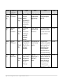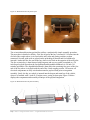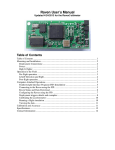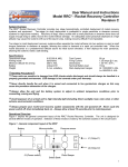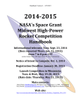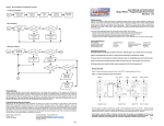
1
NASA Student Launch Project
Flight Readiness Review
2013-2014
April 18, 2014
Table of Contents
I) Summary of Report ...................................................................................................................... 1!
1. Team Summary ....................................................................................................................... 1!
2. Launch Vehicle Summary ....................................................................................................... 1!
3. Payload Summary .................................................................................................................... 1!
II) Changes Made Since CDR ......................................................................................................... 2!
1. Changes Made to Vehicle Criteria .......................................................................................... 2!
2. Changes Made to Payload Criteria .......................................................................................... 2!
Hazard Detection ................................................................................................................. 2!
Tesseract .............................................................................................................................. 3!
3. Changes Made to Project Plan ................................................................................................. 3!
4. CDR Feedback......................................................................................................................... 3!
III) Vehicle Criteria ......................................................................................................................... 5!
1. Design and Construction of Vehicle........................................................................................ 5!
Design and Construction of Launch Vehicle........................................................................... 5!
Body .................................................................................................................................... 5!
Centering Rings, Bulkheads, and Fins ................................................................................ 6!
Electrical Elements .............................................................................................................. 6!
a.!
Avionics Bay.......................................................................................................... 6!
b.! Booster Section ...................................................................................................... 7!
c.!
Switches ................................................................................................................. 8!
d.! Connectors ............................................................................................................. 9!
e.!
Battery Retention ................................................................................................... 9!
Drawings and Schematics.................................................................................................. 10!
a.!
Nose Cone and Drogue Bay................................................................................. 11!
b.! Avionics Bay........................................................................................................ 12!
c.!
Main Bay.............................................................................................................. 13!
d.! Booster Section .................................................................................................... 14!
Flight Reliability and Confidence ......................................................................................... 15!
Airframe ............................................................................................................................ 15!
Construction Jigs ............................................................................................................... 15!
a.!
Fin Marking Jig .................................................................................................... 16!
b.! Tube Slotting Jig .................................................................................................. 16!
c.!
Guillotine Fin Alignment Jig ............................................................................... 17!
Hardware ........................................................................................................................... 17!
Software ............................................................................................................................. 17!
Recovery System ............................................................................................................... 18!
Test Data and Analysis .......................................................................................................... 18!
Airframe Staging ............................................................................................................... 18!
Component Testing ........................................................................................................... 19!
i | Citrus College Rocket Owls – Flight Readiness Review
Workmanship ........................................................................................................................ 24!
Safety and Failure Analysis ................................................................................................... 24!
Full Scale Launch Results ..................................................................................................... 28!
First Test Flight ................................................................................................................. 28!
Second Test Flight ............................................................................................................. 30!
Third Test Flight ................................................................................................................ 31!
Mass Report ........................................................................................................................... 33!
2. Recovery Subsystem ............................................................................................................. 34!
Robustness of Recovery System. .......................................................................................... 34!
Structural Elements ........................................................................................................... 34!
Electrical Elements ............................................................................................................ 34!
Redundancy Features......................................................................................................... 34!
Parachute Sizes and Descent Rates ................................................................................... 35!
Drawings and Schematics of the Electrical and Structural Assemblies ............................ 35!
Rocket-Locating Transmitters ........................................................................................... 36!
Sensitivity of Recovery System to Onboard Devices............................................................ 37!
Suitable Parachute Size ......................................................................................................... 37!
Safety and Failure Analysis ................................................................................................... 38!
3. Mission Performance Predictions .......................................................................................... 39!
Mission Performance Criteria................................................................................................ 39!
Flight Profile Simulations...................................................................................................... 39!
Thoroughness and Validity of Analysis ................................................................................ 41!
Scale Modeling Results ......................................................................................................... 43!
Stability Margin ..................................................................................................................... 43!
Kinetic Energy ....................................................................................................................... 44!
Launch Vehicle Altitude and Drift Calculations ................................................................... 44!
4. Verification (Vehicle) ............................................................................................................ 45!
5. Safety and Environment (Vehicle) ........................................................................................ 49!
Safety Officer ........................................................................................................................ 49!
Analysis of the Failure Modes, Payload Integration, and Launch Operations ...................... 49!
Listing of Personnel Hazards and Safety Hazard Data ......................................................... 58!
Launch Site Safety ................................................................................................................. 58!
Certification ........................................................................................................................... 58!
Motor and Black Powder Handling and Storage ................................................................... 58!
Adhesive Safety ..................................................................................................................... 59!
Tool Safety ............................................................................................................................ 59!
Environmental Concerns ....................................................................................................... 60!
Disposal of Batteries.......................................................................................................... 61!
Disposal of Rocket Motors ................................................................................................ 61!
Disposal of Adhesives ....................................................................................................... 61!
ii | Citrus College Rocket Owls – Flight Readiness Review
Impact of Environment on the Rocket................................................................................... 61!
6. Payload Integration ................................................................................................................ 62!
Payload Integration ................................................................................................................ 62!
Hazard Detection ............................................................................................................... 62!
LVIS .................................................................................................................................. 65!
Tesseract ............................................................................................................................ 65!
IV) Payload Criteria ...................................................................................................................... 68!
1. Experiment Concept .............................................................................................................. 68!
Creativity and Originality ...................................................................................................... 68!
Hazard Detection ............................................................................................................... 68!
LVIS .................................................................................................................................. 68!
Tesseract ............................................................................................................................ 68!
Uniqueness or Significance ................................................................................................... 68!
Hazard Detection ............................................................................................................... 68!
LVIS .................................................................................................................................. 69!
Tesseract ............................................................................................................................ 69!
2. Science Value ........................................................................................................................ 70!
Science Payload Objectives ................................................................................................... 70!
Hazard Detection ............................................................................................................... 70!
LVIS .................................................................................................................................. 70!
Tesseract ............................................................................................................................ 70!
Mission Success Criteria ....................................................................................................... 70!
Hazard Detection ............................................................................................................... 70!
LVIS .................................................................................................................................. 71!
Tesseract ............................................................................................................................ 71!
Experimental Logic, Scientific Approach, and Method of Investigation. ............................. 71!
LVIS .................................................................................................................................. 71!
Tesseract ............................................................................................................................ 72!
Test and Measurement, Variables and Controls. ................................................................... 73!
LVIS .................................................................................................................................. 73!
Tesseract ............................................................................................................................ 73!
Relevance of Expected Data .................................................................................................. 74!
Hazard Detection ............................................................................................................... 74!
LVIS .................................................................................................................................. 74!
Tesseract ............................................................................................................................ 74!
Experiment Process Procedures ............................................................................................ 75!
Hazard Detection ............................................................................................................... 75!
LVIS .................................................................................................................................. 75!
Tesseract ............................................................................................................................ 76!
3. Payload Design ...................................................................................................................... 78!
iii | Citrus College Rocket Owls – Flight Readiness Review
Design and Construction of the Payload ............................................................................... 78!
Structural Elements ........................................................................................................... 78!
a.!
Hazard Detection ................................................................................................. 78!
b.! LVIS..................................................................................................................... 79!
c.!
Tesseract .............................................................................................................. 79!
Electrical Elements ............................................................................................................ 81!
a.!
Hazard Detection ................................................................................................. 81!
b.! LVIS..................................................................................................................... 81!
c.!
Tesseract .............................................................................................................. 83!
Drawings and Schematics.................................................................................................. 84!
a.!
Hazard Detection ................................................................................................. 84!
b.! LVIS..................................................................................................................... 85!
c.!
Tesseract .............................................................................................................. 86!
Precision of Instrumentation and Repeatability of Measurement ......................................... 88!
LVIS .................................................................................................................................. 88!
Tesseract ............................................................................................................................ 88!
Flight Performance Predictions ............................................................................................. 89!
Hazard Detection ............................................................................................................... 89!
LVIS .................................................................................................................................. 89!
Tesseract ............................................................................................................................ 90!
Workmanship ........................................................................................................................ 90!
Test and Verification Program .............................................................................................. 91!
4. Verification ............................................................................................................................ 92!
System Level Functional Requirements ................................................................................ 92!
Hazard Detection ............................................................................................................... 92!
Tesseract ............................................................................................................................ 93!
Analysis, Inspection, and/or Test .......................................................................................... 94!
Hazard Detection ............................................................................................................... 94!
LVIS .................................................................................................................................. 94!
Tesseract ............................................................................................................................ 95!
5. Safety and Environment (Payload) ........................................................................................ 98!
Safety Officer ........................................................................................................................ 98!
Payload Analysis of Failure Modes ....................................................................................... 98!
Failure Modes and Effects Analysis .................................................................................... 100!
Hazards ................................................................................................................................ 102!
Electronic Safety ............................................................................................................. 102!
Welding Safety ................................................................................................................ 102!
Environmental Concerns ......................................................................................................... 102!
V) Launch Operations Procedures............................................................................................... 103!
1. Checklist .............................................................................................................................. 103!
iv | Citrus College Rocket Owls – Flight Readiness Review
Recovery Preparation .......................................................................................................... 103!
Motor Preparation ................................................................................................................ 103!
Igniter Installation ............................................................................................................... 104!
Setup on Launcher ............................................................................................................... 104!
Launch Procedure ................................................................................................................ 105!
Troubleshooting ................................................................................................................... 105!
Post-Flight Inspection .......................................................................................................... 105!
2. Safety and Quality Assurance ............................................................................................. 106!
VI) Project Plan ........................................................................................................................... 107!
1. Budget Plan ......................................................................................................................... 107!
2. Funding Plan ........................................................................................................................ 109!
3. Timeline ............................................................................................................................... 111!
4. Educational Engagement Plan ............................................................................................. 112!
VII) Conclusion ........................................................................................................................... 116!
List of Tables
Table 1: Payload Selections............................................................................................................. 1!
Table 2: Component Test Data ...................................................................................................... 19!
Table 3: Safety and Failure Analysis............................................................................................. 25!
Table 4: Parachute Sizes, Mass of Sections, Descent Rates, and Kinetic Energies ...................... 35!
Table 5: Stability Margin............................................................................................................... 43!
Table 6: Drift Table ....................................................................................................................... 44!
Table 7: Requirements and Verification........................................................................................ 45!
Table 8: Greatest Vehicle Risks .................................................................................................... 50!
Table 9: Vehicle Failure Modes .................................................................................................... 52!
Table 10: Propulsion Failure Modes ............................................................................................. 54!
Table 11: Recovery Failure Modes ............................................................................................... 55!
Table 12: Tool Safety .................................................................................................................... 59!
Table 13: Environmental Impact on the Rocket ............................................................................ 61!
Table 14: Accuracy of Measurements ........................................................................................... 75!
Table 15: Hazard Detection Flight Performance Predictions ........................................................ 89!
Table 16: LVIS Flight Performance Predictions ........................................................................... 89!
Table 17. Tesseract Flight Performance Predictions ..................................................................... 90!
Table 18: Hazard Detection Functional Requirements.................................................................. 92!
Table 19: LVIS Functional Requirements ..................................................................................... 93!
Table 20: Tesseract Functional Requirements .............................................................................. 93!
Table 21: Tesseract Verification Test............................................................................................ 95!
Table 22: Hazard Detection Failure Modes................................................................................... 98!
Table 23: In Line Motor Failure Modes ........................................................................................ 99!
Table 24: Tesseract Failure Modes................................................................................................ 99!
v | Citrus College Rocket Owls – Flight Readiness Review
Table 25: Failure Modes and Effects Analysis............................................................................ 100!
Table 26: Checklist for Recovery Preparation ............................................................................ 103!
Table 27: Checklist for Motor Preparation .................................................................................. 103!
Table 28: Checklist for Igniter Installation ................................................................................. 104!
Table 29: Checklist for Setup on Launcher ................................................................................. 104!
Table 30: Checklist for Launch Procedure .................................................................................. 105!
Table 31: Checklist for Troubleshooting ..................................................................................... 105!
Table 32: Checklist for Post-Flight Inspection ............................................................................ 105!
Table 33: Launch Operations Procedures Risks and Mitigations ............................................... 106!
Table 34: Overall Budget ............................................................................................................ 107!
Table 35: General Rocket Materials Budget Breakdown ............................................................ 107!
Table 36: Motor Materials Budget Breakdown ........................................................................... 107!
Table 37: Hazard Detection Budget ............................................................................................ 108!
Table 38: Tesseract Budget ......................................................................................................... 108!
Table 39: Travel Budget .............................................................................................................. 108!
Table 40: Fundraising Breakdown .............................................................................................. 110!
Table 41: Types of Evaluation Used in Outreach ....................................................................... 112!
Table 42: Outreach and Educational Engagement Events........................................................... 112!
List of Figures
Figure 1: Cut Blue Tube .................................................................................................................. 5!
Figure 2: Laser Cut Centering Rings, Bulkheads and Fins ............................................................. 6!
Figure 3: Bulkheads drying ............................................................................................................. 6!
Figure 4: Official Scoring Altimeter Schematics ............................................................................ 7!
Figure 5: Booster Section Altimeter ................................................................................................ 8!
Figure 6: Rotary Power Switch ....................................................................................................... 8!
Figure 7: Micro Connector .............................................................................................................. 9!
Figure 8: Full Diagram of Project Lambda ................................................................................... 10!
Figure 9: Exploded View of Nose Cone........................................................................................ 11!
Figure 10. Exploded View of Avionics Bay ................................................................................. 12!
Figure 11. Exploded View of the Main Bay.................................................................................. 13!
Figure 12. Exploded View of the Booster ..................................................................................... 14!
Figure 13: Fin Marking Jig ............................................................................................................ 16!
Figure 14: Tube Slotting Jig .......................................................................................................... 16!
Figure 15: Guillotine Fin Alignment Jig ....................................................................................... 17!
Figure 16: Risk Matrix Chart ........................................................................................................ 24!
Figure 17: Project Lambda on the Launch Pad ............................................................................. 28!
Figure 18: The Rocket Owls and Project Lambda ........................................................................ 28!
Figure 19: First Full Scale Flight Altitude Data from Avionics Bay Raven3 ............................... 29!
Figure 20: Second Full Scale Flight Altitude Data from Avionics Bay Raven3........................... 31!
vi | Citrus College Rocket Owls – Flight Readiness Review
Figure 21: Third Full Scale Flight Altitude Data from Avionics Bay Raven3 ............................. 33!
Figure 22: Mass Distribution Chart ............................................................................................... 33!
Figure 23: Seperation of Rocket Sections with Shock Cord Attachment ..................................... 36!
Figure 24: Recovery Attachment Scheme ..................................................................................... 37!
Figure 25: Flight Profile Simulation.............................................................................................. 39!
Figure 26: Actual Flight Data ........................................................................................................ 40!
Figure 27: Cesaroni K1620-Vmax Thrust Curve .......................................................................... 40!
Figure 28: Cesaroni L985TT Thrust Curve ................................................................................... 41!
Figure 29: Project Lambda Coefficient of Drag ............................................................................ 42!
Figure 30: CG and CP with Booster Section ................................................................................. 44!
Figure 31: CG and CP without Booster Section ............................................................................ 44!
Figure 32: Hazard Detection Payload Interface Visual ................................................................. 63!
Figure 33: Hazard Detection Payload Layout ............................................................................... 64!
Figure 34: Hazard Detection Payload Assembly........................................................................... 64!
Figure 35: Tesseract Payload Integration ...................................................................................... 67!
Figure 36: L2 Recovery Tether ..................................................................................................... 79!
Figure 37: Nose Cone with All Thread Assembled....................................................................... 79!
Figure 38: Electrical Diagram of Raven3 and RockeTiltometer Configurations .......................... 83!
Figure 39: Conductive Nose Cone ................................................................................................ 83!
Figure 40: Hazard Detection Schematics ...................................................................................... 84!
Figure 41: LVIS 3D Diagram ........................................................................................................ 85!
Figure 42: Simplified Version of Voltmeter ................................................................................. 86!
Figure 43: Wiring Assembly of Voltmeter Subsystem ................................................................. 86!
Figure 44: Wiring Assembly of CubeSat Subsystem .................................................................... 87!
Figure 45: Ground Station Subsystem ........................................................................................... 87!
Figure 46: 3D Drawing and Actual CubeSat Chassis ................................................................... 88!
vii | Citrus College Rocket Owls – Flight Readiness Review
I) Summary of Report
1. Team Summary
The Citrus Rocket Owls are a team of 8 students from Citrus College, a team advisor, and a team
mentor. The team mentor, Rick Maschek, is Tripoli Level 2 certified (TRA #11388).
The Rocket Owls can be reached at:
Website:
http://amiwa.com/rocketowls/
Email:
[email protected]
Address:
1000 W Foothill Blvd,
Glendora, CA 91741
2. Launch Vehicle Summary
The team’s rocket, Project Lambda, will be 144 inches in length with a 6 inch diameter, and a
total pad weight of 52.4 lbs. The vehicle will have two motors staged in line. The first motor, the
main motor, will be a Cesaroni K1620-Vmax. The second motor, the sustainer, will be a
Cesaroni L985TT. An 85 inch hexagonal shaped ripstop nylon drogue chute will be deployed at
apogee to slow the descent to 54 ft/s. At 1200 ft. AGL, a 120 inch main parachute will deploy
and bring the rocket’s descent to 15 ft/s. The booster section, that detaches to allow the sustainer
to airstart, will contain its own 60 inch hexagonal shaped parachute. The rail size for this rocket
is 12 ft. and the button size is 1.5 inches.
The Milestone Review Flysheet can be found in the documents section of the team website.
3. Payload Summary
The team has chosen to incorporate the following payloads in the launch vehicle:
Table 1: Payload Selections
Payload Title
Hazard Detection
CubeSat System (Tesseract)
Lateral Vibration In Line System (LVIS)
SOW Requirement Number
3.1.1. 3.1.2. 3.1.3.
3.2.2.3.
3.2.1.1.
The primary objective of Project Lambda is to study triboelectric charging, research and analyze
solid propellant rocket motors for in line and parallel staging, and implement a Hazard Detection
System for the safe landings of launch vehicles. In order to complete these objectives, Project
Lambda will be designed with a Hazard Detection System for safe landings, a CubeSat system
for triboelectric studies, and will utilize a multi-stage flight system for staging and motor
analysis.
1 | Citrus College Rocket Owls – Flight Readiness Review
II) Changes Made Since CDR
1. Changes Made to Vehicle Criteria
To ensure all parachutes and electrical components have enough room within the rocket, the
length of the rocket has been increased from 130 inches to 144 inches. As such, the pad weight
has also changed from 45.5 lbs to 52.4 lbs. This has also changed the predicted altitude from
8000 ft. AGL to an altitude closer to 7000 ft. AGL.
The separation of the booster section from the main bay no longer uses a black powder charge
located between two centering rings of the sustainer motor. Instead, the team has opted to use a
simpler method, where the black powder charge is located on the bulkhead at the very end of the
coupler that connects the booster section to the main bay. However, the PVC case that contains
the black powder charge is inverted, and small holes have been drilled through the side of the
PVC pipe, so when the charge is ignited, the hot gases will travel outwards to over pressurize the
compartment, instead of traveling up and accidentally igniting the sustainer. As a precaution, a
piece of masking tape is also placed across the sustainer before launch to prevent premature
ignition.
In addition, a PerfectFlite miniTimer4 is being used as a redundant timer to ignite the sustainer.
This will be hooked up in parallel with the Raven3, and one lead will go out from that circuit to
the RockeTiltometer. The PerfectFlite miniTimer4 is programmed to send out a charge at 2.75
seconds, 0.25 seconds after the Raven3 is supposed to ignite the sustainer. This system ensures
that a secondary charge can ignite the sustainer if the Raven3 is unable to do so.
2. Changes Made to Payload Criteria
Hazard Detection
The mechanism of detachment for the detachable bulkhead has changed. In lieu of using nylon
cords to secure the detachable bulkhead, the team has devised a safer and more practical method.
A heat-treated, copper-toned, anodized aluminum recovery tether will be used to attach the
detachable bulkhead to the forward bulkhead of the avionics bay. The tether will contain a set of
quicklinks on either side (attached to the detachable bulkhead and forward bulkhead of the
avionics bay) that are interlocked via a pin system. A compartment for black powder will be
internally located within the tether system, and when the main parachute is deployed, a charge
will also be sent to the tether system. The black powder charge will then pressurize the
compartment and separate the pin lock system, which in turn, will disengage the detachable
bulkhead. Further details on the system are located in Payload Design portion of the report.
Additionally, the payload sleds in the avionics bay have been changed from polycarbonate to
birch plywood. Birch plywood is easy to machine with the laser cutter, which produces more
precise and exact results. Also, the official scoring altimeter has been changed to a Raven3
accelerometer and its power source has been changed from a standard 9V battery to an advanced
lithium 9V battery. The Raven3 can perform multiple tasks, so in order to conserve space, the
Raven3 will act as the official scoring altimeter and measure lateral vibrations simultaneously.
The advanced lithium battery will produce 25 more mA than a standard 9V, which will help
prevent failure of the sustainer motor ignition.
2 | Citrus College Rocket Owls – Flight Readiness Review
Lastly, the camera used for the hazard detection system has changed. Instead of using the
Raspberry pi camera board, a RockSoul USB webcam will be used. The reason for this change is
because the Raspberry Pi itself does not recognize its camera board as a webcam, whereas the
edge detection algorithm is reliant on a webcam.
Tesseract
Changes have been made to the Tesseract payload as well. Upon testing of the electrometer, this
system was deemed unfit to record charge due to major discrepancies in recorded measurements.
The system has been replaced with a new circuit that contains a capacitor. The capacitor will be
connected to the nose cone and a ground and a new voltmeter system will measure the potential
difference across each end of the capacitor.
The signal-to-noise ratio measurements were also scrapped due to the complexity of measuring
such signals. Research did not show how something like this could be done so the team decided
to move in a different direction and change the research question. The team is now investigating
the relationship between triboelectric charging and altitude. Now the altitude sensor data is
directly related to the experiment. The coating on the outside of the nose cone has been changed
from carbon fiber to carbon paint due to the cost of having a carbon fiber nose cone
manufactured. The nose cone no longer has an aluminum tip, because of the lack of availability
of resources and
3. Changes Made to Project Plan
Several outreaches were added to the project plan schedule, including the Chinese Institute of
Engineers STEM Seminar, and an outreach at the Glendora Public Library.
4. CDR Feedback
1. We like that the team has taken the initiative to make the decision to get rid of the parallel
boosters. It’s a good learning experience to actively back off of a technical challenge in order
to meet the project requirements.
The team sincerely appreciates the feedback, as this is the type of experience and feedback the
members were hoping to gain from participating in this research project.
2. What altitude will the rocket be when the booster motor burns out? (booster separates at
730 ft.)
Due to a larger, heavier rocket, the booster now separates at 360 ft.; therefore, the booster
motor burns out at about 230 ft.
3. How long after main motor burnout will the command be sent to light the second stage
igniter?
The second stage will ignite 2.5 seconds after liftoff, which is 0.97 seconds after main motor
3 | Citrus College Rocket Owls – Flight Readiness Review
burnout.
4. The RockeTiltometer2 actively records the angle of attack of the rocket. What are the
constraints within that algorithm?
According to the user’s manual, time constraints have been improved from the first
RockeTiltometer as the Direction Cosine Matrix used is specific to “attitude- transformation”
and therefore are faster and no longer contain null solutions.
5. Why wait 1.5 seconds after 1st stage burnout to separate the stages?
There will now be a 0.97 second delay between main motor burn out and sustainer ignition.
6. We recommend separating the stages just after main motor burnout, then 1 to 1.5 seconds
after main motor burnout, send the command to light the 2nd stage. The motors will probably
not come up to full pressure immediately, so the time table from 1st stage burnout to 2nd stage
ignition will be close to the same.
After taking this advice into account, the team has changed the delay between the main motor
burnout and sustainer ignition to be 0.97 seconds.
7. Are all of the electronics for the sustainer motor in the sustainer?
Yes, the electronics include a RockeTiltometer2, a Raven3 for the airstart ignition, and a
backup PerfectFlite miniTimer4, in the event that the Raven3 malfunctions, will all be housed
in the Sustainer Motor and Raven3 Trigger (SMART) bay above the sustainer motor.
4 | Citrus College Rocket Owls – Flight Readiness Review
III) Vehicle Criteria
1. Design and Construction of Vehicle
Design and Construction of Launch Vehicle
Project Lambda is specifically designed to research the following topics: the lateral vibrations of
a rocket during its thrust phase; the ramifications of triboelectric charging on communications
signals; and the effectiveness of utilizing an edge detection system to relay potential landing
hazards. In order to successfully accomplish Project Lambda's mission, key vehicle design
features were implemented. These features include: multiple stages to study lateral vibrations; a
conductive nose cone working in conjunction with a CubeSat and voltmeter to study triboelectric
charging; and a detachable bulkhead that allows the vehicle to reorient itself during its descent
phase in order to scan and detect potential hazards on the intended landing surface. The
construction methods used to complete these key design features are further detailed below.
Body
Figure 1: Cut Blue Tube
The main sections of the body started as two 48 inch
and one 72 inch body tube. The coupler section started
out as one 48 inch tube. The sections were measured out
and a Miter saw was used to cut the tubes into the
desired sizes. The coupler tube was manufactured in the
same way. Five different body tube sections were cut
and two coupler sections were cut. Extra body and
coupler sections were cut out to make two stiffy tubes.
This was done by cutting the extra pieces down the
length of the tube. Then, another cut was made down
the length of the tube. The distance from the first cut to
the second cut was calculated so that the stiffy tube
would fit perfectly within the coupler or body tube.
Using epoxy, the coupler sections were attached to their
respective body tube sections. The stiffy tube was also
epoxied in, but only after the electronics mounts were
built and successfully fit to their sections.
5 | Citrus College Rocket Owls – Flight Readiness Review
Centering Rings, Bulkheads, and Fins
Figure 2: Laser Cut Centering Rings, Bulkheads and Fins
Figure 3: Bulkheads drying
All the centering rings, bulkheads, and fins were drawn out on a Computer Aided Design (CAD)
program. The drawings were used by a laser cutter and all of these materials were then cut with a
precision of ±0.025 mm. Due to the restriction of the thickness of the wood used, each centering
ring and bulkhead was made up of two or four individually cut pieces. For example, the drogue
bulkhead, which will experience a significant amount of force during parachute deployment, was
made up of four, 1/4 inch, bulkheads that were identical. The four pieces were glued and
clamped together to ensure that none of the pieces would be misaligned.
Electrical Elements
a. Avionics Bay
The recovery system incorporates the use of redundant altimeters and black powder charges for
both main and drogue parachute bays in attempt to negate the risks of deployment failure. The
scoring altimeter will be comprised of a Raven3 altimeter. This microcontroller has the
capability of handling up to four events, and can be set to trigger deployment at a specified
altitude as pressure is increasing, adjustable in 32 foot increments, or a time delay after initial
thrust. A Missile Works RRC2 mini will be employed as a redundancy. This altimeter also has
the capability of triggering deployment at a specific altitude as pressure is increasing, adjustable
in 100 foot increments, or a time delay after a specified altitude. The Raven3 is set to fire its
drogue charge at apogee, and the main charge ate 1200 ft. AGL. The RRC2 mini is set to deploy
its drogue and main parachutes 2 seconds after apogee and 1200 ft. AGL respectively. Each
altimeter is equipped with its own power source, and the two are wired independently as shown
in Figure 4 below.
6 | Citrus College Rocket Owls – Flight Readiness Review
Figure 4: Official Scoring Altimeter Schematics
b. Booster Section
The booster section is designed to jettison from the main airframe of the rocket after main motor
burnout. For that reason, it will require its own recovery subsystem. This includes a Raven3
altimeter, which will be located in the booster system to execute all necessary separation
commands. This Raven3 is set to separate the booster section from the sustainer two seconds
after liftoff, or 0.47 seconds after main motor burnout. It is also programmed to deploy the
booster section parachute once pressure starts to increase, or as the booster section reaches its
relative apogee. The fourth channel of the altimeter will be programed will detonate the back
parachute e-match 2 seconds after the booster section reaches its relative apogee. The wiring
schematic for the booster section’s recovery electronics are shown below in Figure 5.
7 | Citrus College Rocket Owls – Flight Readiness Review
Figure 5: Booster Section Altimeter
c. Switches
The on board altimeters are each controlled by independent 2-pole rotary power switches which
are installed on the exterior of the payload bays. These heavy-duty switches are equipped with
high detent spring-loaded cams to ensure that launch forces do not flip them. Additionally, they
are rated for up to 250 V at 6.3A, which will accommodate the altimeter’s requirements.
Figure 6: Rotary Power Switch
8 | Citrus College Rocket Owls – Flight Readiness Review
d. Connectors
A 4-conductor Micro Connector F04-200 has been added to each bulkhead and switch wire. Not
only does this guarantee a great deal of ease with regards to electronic hardware integration, but
it allows for the altimeters and bulkheads to be detached without the removal of any wiring.
Furthermore, these connectors are equipped with a positive locking mechanism. Therefore, the
fastener cannot work loose from vibrations induced by the rocket flight.
Figure 7: Micro Connector
e. Battery Retention
All of the batteries used for the altimeters that control the recovery events of the vehicle will be
mounted with Philimore 9 V battery holders. These will be screwed into the electronic sleds of
each section using #4-40 screws and nuts. The battery allows for soldering points on top of the
holders so the wires do not become loose. They also restrict horizontal movement but the team
will add additional cable ties for positive retention. The batteries will be oriented in such a way
as to have the battery push into place during the thrusting phase.
9 | Citrus College Rocket Owls – Flight Readiness Review
Drawings and Schematics
The following drawings show the full rocket, as well as different components of each section and
how they will come together to form the different sections of the rocket.
Figure 8: Full Diagram of Project Lambda
10 | Citrus College Rocket Owls – Flight Readiness Review
a. Nose Cone and Drogue Bay
Figure 9 shows the order that the different components of the nose cone and drogue bay will fit
together. This section consists of four bulkheads, two of which have a square indentation to hold
the CubeSat. There is also a centering ring with a square cutout and an electronics sled. All of
these will be held in by three all threads. These all threads will go through 0.25 inch holes cut out
in specific places in the bulkheads and centering ring.
Figure 9: Exploded View of Nose Cone
11 | Citrus College Rocket Owls – Flight Readiness Review
b. Avionics Bay
Figure 10 shows the order that the different components of the avionics bay will fit together. The
coupler tube is longer than the body tube and will hold the electronics. A stiffy tube will be
inside and will prevent the electronics from sliding up and down. There will be four bulkheads in
this section. All threads will create a solid connection between two of the bulkheads and the
stiffy tube and the top most bulkhead will be detachable. It will hold onto another bulkhead
through nylon cord. The avionics for the rocket will fit between two bulkheads and the hazard
detection will fit between two other bulkheads.
Figure 10. Exploded View of Avionics Bay
12 | Citrus College Rocket Owls – Flight Readiness Review
c. Main Bay
Figure 11 shows how the different components of the main bay will fit together. The main bay
contains 5 centering rings designed to fit a 54 mm sustainer motor. Also, 3 delta fins will fit into
slots in the body tube. There will be a bulkhead that will sit directly above the sustainer motor,
and a second bulkhead at the very top of the main bay. Between these bulkheads will be the
Sustainer Motor and Raven3 Trigger (SMART) bay, which contains the electronics to control the
ignition of the sustainer, as well as the recovery system. There will be conduit that will go
through the centering rings so that the electronics will have a direct line to the sustainer motor.
Figure 11. Exploded View of the Main Bay
13 | Citrus College Rocket Owls – Flight Readiness Review
d. Booster Section
Figure 12 shows different components and how they will be come together to form the booster
section of the rocket. This section is comprised of two body tubes which are the upper and lower
cylindrical pieces. There is also a coupler tube, which will connect the upper section of the
booster to the sustainer and the lower section of the booster. There are 4 centering rings that will
hold the motor in the body tube. There are 3 delta fins that will fit into slots in the lower booster
section. There are also three bulkheads. A recovery system will fit between the middle and lower
bulkhead. The electronics for this section will fit between the upper and middle bulkheads.
Figure 12. Exploded View of the Booster
14 | Citrus College Rocket Owls – Flight Readiness Review
Flight Reliability and Confidence
The team’s primary objective is to design, construct, and successfully launch a high power rocket
capable of compiling data, with the potential to improve future Space Launch Systems (SLS)
technology. Project Lambda is directed towards research pertaining to the lateral vibrations of a
rocket during its thrust phase, the ramifications of triboelectric charging on communications
signals, and the effectiveness of utilizing an edge detection system to relay potential landing
hazards.
The rocket will reach but not exceed an altitude of 7000 ft., after which the dual deploy recovery
system will bring the rocket to a safe landing within 2500 ft. of the launch pad. All safety
regulations defined by NASA’s University Launch Project competition as well as team and
NAR/Tripoli guidelines will be followed when building and operating the rocket. The Rocket
Owls plan to utilize their limited resources to positively represent their school, and community
while providing competition for veteran teams.
All the requirements defined by the mission directorate were used to guide the Rocket Owls’
design decisions. The team’s plan for meeting these requirements will be discussed in the
Requirements and Verification section of the Vehicle Criteria, detailing how each design
requirement has been met. The team will consider their mission a success after they have both
launched and recovered a high-powered rocket built in accordance with the listed design
requirements.
The members of the Citrus Rocket Owls have grown vastly in all aspects of rocketry since the
beginning of the NASA Student Launch Project. Maturity in design aptitude, particularly, is trait
that has been acquired through a great deal of trial and error. Consequently, much of the
originally intended design has been scaled back to accommodate all safety concerns, and the
reliability and confidence of flight success has increased enormously.
With less risk to mitigate, the team was able to focus attention on two key factors, testing and
assembly; which ultimately lead to vehicle reliability and confidence in mission success.
Airframe
Blue Tube 2.0 was utilized for the assembly of the airframe of the vehicle. This composite
material has a high sheer strength, and has been an essential component of many successfully
flown rockets nationwide. Nonetheless, it is important to implement a great level of precision
during the construction process. For the purposes of this research project, the correct tools were
always employed, where the ‘correctness’ of a tool depends on its accuracy and precision. All
body tubes and couplers were carefully cut and sanded. Other critical pieces, such as the fins,
were laser cut with 1/40th of a millimeter of precision.
Construction Jigs
The team constructed jigs to ensure proper placement and alignment of fin slots and fins. All the
jigs were built with laser cut pieces and carefully assembled.
15 | Citrus College Rocket Owls – Flight Readiness Review
a. Fin Marking Jig
Figure 13: Fin Marking Jig
The Fin Marking Jig, shown in Figure 13, was
used to mark the body tube for the fin slots
precisely 120 degrees apart. This simple jig
consists of a laser cut birch plywood piece with
a 6 inch diameter circle cut out of it, and
marked every 60 degrees with laser precision
(1/40th of a millimeter). The body tube is placed
inside the circular cutout, and a line is simply
drawn up the side to mark the position of the fin
slots.
b. Tube Slotting Jig
The Tube Slotting Jig, shown in Figure 14, was used to create the slots for the fins on both the
booster section and the main bay. The body tube was held in place inside the jig, while the router
was inserted through the cutout at the top to make a precise slot for the fins.
Figure 14: Tube Slotting Jig
16 | Citrus College Rocket Owls – Flight Readiness Review
c. Guillotine Fin Alignment Jig
Figure 15: Guillotine Fin Alignment Jig
Figure 15 depicts a Guillotine Fin Alignment Jig,
constructed based on a design provided to the
team by Ted Macklin of Apogee Rockets. The
rocket’s airframe rests inside the jig, while the fin
is inserted through the steel guiderails at an angle
precisely 90 degrees from the rocket airframe.
The fin is then held firmly in place until the
epoxy cures, thus ensuring maximum precision in
fin alignment.
Hardware
All electronic hardware pertaining to the scientific payloads and recovery systems were
thoroughly tested before implementation into the full scale rocket. This includes, but is not
limited to, the Raven3 altimeters responsible for all black powder separations, the RRC2 mini
altimeter utilized as a redundancy for main and drogue bay separations, and the PerfectFlite
miniTimer4 which will be used as a redundancy to airstart the sustainer motor, Testing and
calibration was performed to ensure that all hardware functioned accurately and precisely
according to manufacturer specifications. Furthermore, all electronic beds were carefully
assembled so as to ensure that expensive electronic equipment is not damaged or dislodged
during flight.
Test results, particularly from the subscale test, show that the accelerometer-based altitude
readings recorded by the Raven3 altimeter were not accurate. However, further research
indicated that the manufacturer expected a high level of inaccuracy in these values. As a result,
barometric altitude data is utilized in post flight analysis.
Testing also revealed that the onboard camera that accompanied the Raspberry Pi did not work in
collaboration with the custom edge detection algorithm to scan for potential landing hazards.
Instead, a USB webcam was integrated, and the hardware problem was alleviated.
Software
All software packages were custom designed by members of the Citrus Rocket Owls. To ensure
that commands will be executed as planned during flight, the software was heavily tested not
only through static tests, but also in motion as to simulate flight conditions. Further information
about software testing and reliability can be found in the payload testing portion of the design
review.
17 | Citrus College Rocket Owls – Flight Readiness Review
Recovery System
In compliance with vehicle requirement 2.3 in the Statement of Work, all parachute systems in
the vehicle were designed and manufactured by the team. Precession in assembly of the recovery
subsystem was crucial in contributing to flight reliability and confidence. The team-designed
parachutes were carefully sown with nylon thread. Rather than being attached to grummets, the
shock cords were sown into the seams of the parachute such that they converge to the center.
This design allows the shock cords to have many points of contact with the parachute so that the
forces distribute properly. A proper technique was established and tested for the folding and
packing of all parachutes with their accompanying harnesses. In addition, all separation charges
were tested statically prior to test flights. Further detail regarding construction methods and
recovery testing can be found in the recovery subsystem section of the design review.
Test Data and Analysis
Airframe Staging
During the flight of Project Lambda, the booster section will separate from the main bay via a
black powder charge 0.47 seconds after the main motor burns out. The black powder charge is
located on the top bulkhead in the coupler that connects the booster section and the main bay.
Testing was conducted to determine exactly how much black powder was required to ensure the
separation occurs without damaging the rocket in any way.
To determine the amount of black powder required, the following equation was used: Amount of
black powder (g) = (diameter of compartment in inches)2 x (length of compartment in inches)2 x
0.006. As the diameter of the compartment is 6 inches, and the length of the compartment is 2.25
inches, the total amount of black powder needed was calculated to be 1.35 g.
After construction, the rocket was laid on the rocket stand, and a ¾ inch PVC cap was filled with
1.35 g black powder. Unlike usual black powder charges, the PVC cap was inverted, and small
holes drilled through the side. This was done so that when the black powder charge ignites to
over pressurize the compartment, there is no chance of it also igniting the sustainer motor, which
is located directly above the coupler.
An igniter was inserted, and the booster section and main bay were connected. Two shear pins
were also inserted. At this point, the team performed a safety check to ensure the area was clear,
and that no hazardous substances were located anywhere near the rocket. After the all clear, the
black powder charge was ignited. The rocket separated instantly and successfully, without
damaging the interior in any way.
During the first full scale flight, the team yet again used 1.35 g of black powder for the airframe
separation. The booster section and main bay separated exactly as predicted in flight, without
excessive force. The rocket was not damaged whatsoever by the black powder charge. Further
details on the results of the full scale flight can be found under full scale launch test results.
18 | Citrus College Rocket Owls – Flight Readiness Review
Component Testing
Table 2: Component Test Data
Location
Mini
Avionics
Bay
Component or
Subsystem
Component:
Raven3
accelerometer
Test Type
Static
Ground
Test
Mini
Avionics
Bay
Subsystem:
LVIS- Raven3
Static
Mini
Avionics
Bay
Component:
Raven3
Barometer
Functional
Mini
Avionics
Bay
Component:
Raven3 Timer
Functional
Ground
Test
Ground
Test
Full-scale
Flight
Purpose
Results
Details
Status
To determine
proper
accelerometer
calibration to
ensure data
collected is
accurate.
To ensure proper
functionality of
Raven3 with use
of a flight
simulation.
Live data from the
accelerometer was
0.83 axial G’s.
Live data determined by
manufacturer should be
.8-1.2 axial G’s to ensure
properly calibrated.
Successful
Flight simulation was
successful without
anomalies.
Successful
To ensure
barometric
pressure sensor
functions
properly for
deployment of
booster
parachute.
To ensure that the
stages separate at
two seconds
using flight logic
Raven3 worked as
planned
The Raven3 flight
simulation was completed
using the manufacturer’s
flight profile software.
The flight simulation
showed that the Raven3
was properly functioning.
Tested using a bell jar
with an LED in the pyro
pin of the Raven3 and
programmed to send a
current if the barometric
pressure within the bell
jar is between
Tested using the full-scale
flight time>2secs.
Successful
19 | Citrus College Rocket Owls – Flight Readiness Review
Stages separated at
two seconds as
planned.
Successful
Location
Mini
Avionics
Bay
SMART
Bay
SMART
Bay
Component or
Subsystem
Subsystem:
LVIS- Raven3
Test Type
Purpose
Functional
To ensure flight
logic was
properly
programmed for
stage separation
and parachute
ejection.
To determine
proper
accelerometer
calibration to
ensure data
collected is
accurate.
To ensure proper
functionality of
Raven3 with use
of a flight
simulation.
Parachute deployed at The pressure increasing
designated altitude
and the altitude greater
using flight logic.
than 512ft.
Successful
Live data from the
accelerometer was
0.95 axial G’s.
Live data determined by
manufacturer should be
.8-1.2 axial G’s to ensure
properly calibrated.
Successful
Flight simulation was
successful without
anomalies.
To ensure that the
charge is sent to
the pyro pin at
the designated
time of
2.5seconds
Ground test
confirmed, timer lit
the LED at 2.5
seconds.
The Raven3 flight
Successful
simulation was completed
using the manufacturer’s
flight profile software.
The flight simulation
showed that the Raven3
was properly functioning.
Jerk test was performed to Successful
simulate a launch and the
Raven3 was set to send
current to the pyro pin
connected to an LED at
2.5 seconds. Current
approximately 1.9 Amps
Full-scale
Flight
Component:
Raven3
accelerometer
Static
Subsystem:
LVIS- Raven3
Static
Ground
Test
Ground
Test
SMART
Bay
Component:
Raven3 Timer
Static
Ground
Test
20 | Citrus College Rocket Owls – Flight Readiness Review
Results
Details
Status
Location
SMART
Bay
Component or
Subsystem
Component:
RockeTiltometer
Test Type
Static
Ground
Test
SMART
Bay
Component:
RockeTiltometer
Static
Ground
Test
SMART
Bay
Component:
RockeTiltometer
Static
Ground
Test
SMART
Bay
Component:
RockeTiltometer
Static
Ground
Test
Purpose
Results
Details
To ensure proper
circuitry of
component.
Ground test
confirmed circuitry
properly connected as
the series three beeps
showed no anomalies.
To ensure
ignition battery
switch functions
properly.
Ground test showed
that once switched
on, the battery was
functioning properly
by the two beeps
heard.
To ensure that the
ignition arming
switch functions
properly
Ground test showed
one switched on, the
ignition arming
switch functioned
properly by the sound
of one beep.
To ensure igniter
will ignite within
critical angle.
Ground test
confirmed that the
igniter would light if
angle of attack is
within the critical
angle
Circuitry was set up as
specified by manufacturer
and throughout the
system’s checks; the
system had three beeps
which confirms that the
circuitry was properly
connected.
The ignition battery
switch was turned on and
the beeping changed to
only two beeps. This
confirms in the user
manual that the ignition
battery switch functions
properly.
The ignition arming
switch was turned on and
the beeping changed from
two to one beep. This
confirms that the system
is properly armed as
stated in the user manual.
Tested using a 6 volt light
bulb and simulated launch
conditions.
21 | Citrus College Rocket Owls – Flight Readiness Review
Status
Successful
Successful
Successful
Successful
Location
SMART
Bay
Component or
Subsystem
Component:
RockeTiltometer
Test Type
Static
Ground
Test
Avionics
Bay
Subsystem:
LVIS- Raven3
Static
Ground
Test
Avionics
Bay
Component:
Raven3
Barometer
Functional
Ground
Test
Purpose
Results
Details
To ensure igniter
will not light if
outside of the
critical angle.
RockeTiltometer2 did
not send current to
the light bulb after
the component was
outside of the critical
angle.
To ensure proper
functionality of
Raven3 with use
of a flight
simulation.
Flight simulation was
successful without
anomalies.
To ensure
barometric
pressure sensor
functions
properly for
deployment of
the drogue and
main parachutes.
Raven3 barometer
detected change in
pressure
The component was
allowed to dynamically
calibrate in a vertical
condition, next a manual
launch was triggered and
the RockeTiltometer was
put outside of the critical
angle and the ignition
signal was sent but no
light appeared as
expected.
The Raven3 flight
simulation was completed
using the manufacturer’s
flight profile software.
The flight simulation
showed that the Raven3
was properly functioning.
Tested using a bell jar
with an LED in the pyro
pin of the Raven3 and
programmed to send a
current if the barometric
pressure within the bell
jar is between
22 | Citrus College Rocket Owls – Flight Readiness Review
Status
Successful
Successful
Successful
Location
Avionics
Bay
Component or
Subsystem
Component:
RRC2 mini
Barometer
Test Type
Purpose
Functional
To ensure
barometric
pressure sensor
functions
properly for
deployment of
the drogue and
main parachutes.
Ground
Test
23 | Citrus College Rocket Owls – Flight Readiness Review
Results
RRC2 mini
barometer detected
change in pressure
Details
Tested using a bell jar
with an LED in the pyro
pin of the RRC2mini and
programmed to send a
current if the barometric
pressure within the bell
jar is between
Status
Successful
Workmanship
The precision that is involved with this project is undoubtedly high. In order to enable mission
success, everything that is completed must be done as best as possible. The team values its work,
and puts all its efforts into doing a proficient job. In designing the rocket, simulations were
carefully examined to ensure that the rocket performed safely and efficiently. When building the
full-scale rocket, the team understands that everything must be precisely manufactured for the
flight to follow the predictions of the models as well as those of the subscale flight.
The team is taking every necessary precaution to ensure that the rocket is constructed properly.
Before construction began, the team researched the best possible methods of construction. Then,
those who wanted to make the components practiced using the tools needed. The rest of the team
determined that the work was up to standard before that person was allowed to proceed to
manufacturing.
The team wants the rocket to function exactly as planned. The rocket must reach the intended
height, the separations must occur at the times that have been decided, the recovery systems must
deploy properly – every phase of construction must be done right in order for the rocket to
perform the way it is supposed to. The team intends to keep a close eye on the construction and
assembly of every piece in order to ensure that everything can be assembled correctly and
functions properly.
Safety and Failure Analysis
The following chart is a standard risk matrix used to identify and rate risks in this project. This
risk matrix utilizes a 1 to 5 scale for both the severity and likelihood of each, where 1 is trivial or
remote, and 5 is fatal or certain. Risks are ranked by the product of its two scores. The risks are
also color coded by risk level where green requires little to no mitigations, yellow requires some
mitigations for the success of the project, and red is absolutely critical for the team to be
successful. This method of ranking is used for all tables with a "Risk Level" column throughout
the FRR. Numbers in parentheses under "Risk Level" is a reevaluated level after significant
mitigation is done to a medium or high risk.
Figure 16: Risk Matrix Chart
24 | Citrus College Rocket Owls – Flight Readiness Review
Table 3: Safety and Failure Analysis
Risk
Causes
Consequence
Mitigation Strategy
Vehicle Testing
Failure
Poor launch day
procedures, poor overall
rocket design, failure of
ignition and recovery
electronics.
Rigorous tests at a system and subsystem level.
All static testing is to be completed before test
launches. A backup rocket body of the same
dimensions in the event the airframe is
damaged beyond use.
Testing Delays
(weather or issues
at the launch site)
Inclement weather,
failure to secure FAA
waiver.
Damage to parts, vehicle,
or payloads. Falling far
behind the timeline because
of the need to rebuild.
Replacement parts do not
fit into the budget.
Falling behind projected
timeline or inability to test
launch by deadline.
Failure of
Electronics (nonrecovery)
Poor programming,
usage of drained or
depleted batteries, poor
handling of electronics
causing a short.
Failure to retrieve data and
reduction to the overall
science value of the
project.
Failure of
Electronics
(recovery)
Poor programming of
avionics, poor wiring to
battery, avionics not
correctly secured on
payload sleds.
Poor wiring to battery,
avionics not correctly
secured on payload
sleds.
Failure of main or drogue
parachutes.
Failure of scoring
altimeter
Failure to report altitude
and failure to score.
25 | Citrus College Rocket Owls – Flight Readiness Review
Risk
Level
16
(9)
Multiple launch sites available to use (FAR,
Lucerne Valley, Santa Fe Dam) Have contacts
at each of the nearby launch sites or clubs. Plan
multiple potential test dates early to avoid bad
weather.
Multiple tests of all electronics. The CubeSat,
voltmeter, hazard detection, recovery
electronics, and scoring altimeter are all on
separate circuits. Also, in order to work on the
electronics in the rocket a member of the team
had to pass several trials demonstrating proper
technique and electronics safety to minimize
failure due to construction.
Use of altimeters with built-in redundancy, that
have passed ground tests. Launch with avionics
that have been flown in test launches and
retested to ensure functionality.
6
(4)
Test scoring altimeter and fly it in test launch
before competition. Housed in the center of the
avionics bay on its own circuit to minimize any
effect by other components, motors, or
parachute deployments.
5
16
(12)
5
Risk
Causes
Consequence
Battery low/failure
Use of drained or
depleted batteries, use
of batteries with
excessive output.
Recovery electronics
cannot deploy parachutes,
payloads cannot collect
data and lose scientific
value.
Hazards During
Transportation and
Handling of
Motors or Black
Powder
Unsafe procedures,
smoking near explosive
materials.
Damage to motor resulting
in unusable motor, failure
to launch, injury and burns.
Availability of
Parts
Damage to current
parts, complex design
requiring more custom
parts.
Shipping
delays/missing
parts
Budget constraints can't
afford expedited
shipping
Delay or stop construction
of rocket or payloads.
There is also a risk of
buying cheaper parts that
are not ideal for the overall
plan of the rocket.
Delay to vehicle or payload
construction and testing.
Failure to meet timeline.
Access to required
tools.
Specialized tool is
required.
Delays in the fabrication of
vehicle parts, failure to
meet timeline.
26 | Citrus College Rocket Owls – Flight Readiness Review
Mitigation Strategy
Appropriate large capacity batteries are used
for payloads to provide power longer than
flight and time on launch pad. Always use a
new battery for altimeters. Checklist has the
safety officer and one other member check all
batteries.
Motors and black powder is only handled by
certified members with the ok of the safety
officer. Both will be transported and stored by
the team mentor or safety officer only. No
smoking within 25 feet of any flammable or
explosive materials.
Design of the main rocket has constantly been
in progress and changes are always checked to
ensure the needed parts are available before
they are finalized.
All parts are ordered early to ensure they arrive
before they are needed. Extra body materials
are ordered to accommodate for missing parts
and changes to design.
General construction was completed at team
members’ houses where a safe work area was
available. More specialized construction such
as laser cutting or welding was done at either
the schools automotive department or at a local
build shop with appropriate tools.
Risk
Level
4
5
3
4
1
Risk
Causes
Access to
sufficient
workspace or
machine shop
Faculty at the schools
automotive department
is not available to open
the shop. School is
closed.
Personnel
Shortage
Health concerns, time
constraints, personal
issues, job offer.
Failure to maintain Insufficient fundraising
budget
efforts, poor overall
design requiring
expensive components,
repair costs of failed
flight.
Consequence
Mitigation Strategy
Risk
Level
1
Delay in fabrication, failure General construction was completed at team
to meet timeline
members’ houses where a safe work area was
available. More specialized construction such
as laser cutting or welding was done at either
the schools automotive department or at a local
build shop with appropriate tools. Build up a
professional relationship with local shops for
our team and future teams.
Loss of momentum in the
Strong communication between team members 1
build process, increase in
and advisors. No part of the project is
workload or remaining
understood by only one team member so all
members resulting in a
parts are still covered in the absence of a team
decrease in workmanship.
member.
Lower quality of parts
The budget is regularly checked during
4
reducing the overall quality meetings and managed by the faculty advisor.
of the rocket and its safety Work hard as a team to follow all mitigations to
factors.
prevent need for repairs.
27 | Citrus College Rocket Owls – Flight Readiness Review
Full Scale Launch Results
First Test Flight
Figure 17: Project Lambda on the Launch Pad
On Sunday, April 13th 2014, the team conducted a full scale test launch of Project Lambda at
Lucerne Valley. The primary purpose of the launch was to verify that the rocket meets every
single requirement specified in the SOW, and also to determine how the actual flight compared
to the subscale and the simulations performed prior to the full scale launch.
Figure 18: The Rocket Owls and Project Lambda
Wind speeds were between 5 mph and
10 mph at ground level. The rocket was
assembled and readied for launch in a
little over an hour. None of the
payloads were placed inside the rocket,
meaning the only avionics on board
were the Raven3 altimeters.
The first stage of the flight was
immensely successful. The booster
section separated after main motor
burnout, just as planned, and the
recovery system deployed when the
booster section reached its own apogee
at 850 ft. AGL. The booster section was
successfully recovered with no damage whatsoever to the rocket or the components inside.
28 | Citrus College Rocket Owls – Flight Readiness Review
Unfortunately, the main motor did not ignite as planned following the detachment of the booster
section. This was not because of any fault in programming the Raven3, but rather due to
insufficient current provided by the battery. This will be resolved by using a lithium ion battery
that will provide more current, enough for sustainer ignition.
This by itself would not have affected the recovery of the rocket body, as the drogue parachute
was set to deploy at 2500 ft., and the main parachute was set to deploy at 1200 ft., if the sustainer
did not ignite. However, since the rocket reached apogee at 1717 ft. AGL, it never reached the
height required to deploy the drogue parachute. As for the main parachute, although the rocket
body separated to allow the main parachute to unfurl, the shock cord had gotten tangled,
preventing the parachute from deploying. As a result, the rocket landed with excessive kinetic
energy, and thus suffered damage to its airframe. However, none of the electronics or
components inside the rocket were damaged in any way, and almost everything except a section
of the body tube was salvageable.
The results of this flight were essential in helping the team recognize areas of the project that
need improvement – for example, packing the parachute properly in launch day procedures.
However, the flight also demonstrated that if the team can improve in this area and use a better
battery, the rocket is aerodynamically sound and should be able to successfully and safely
conduct a multistage flight.
To verify this fact beyond a doubt, the team intends to conduct a second full scale launch on
Sunday, April 20th, 2014. This time, the team will take precautions to pack the shock cord
correctly, and to use a battery that provides enough current to ignite the sustainer.
Figure 19 below shows the barometric altitude data gathered by the Raven3 in the avionics bay,
which will act as the official scoring altimeter.
Figure 19: First Full Scale Flight Altitude Data from Avionics Bay Raven3
29 | Citrus College Rocket Owls – Flight Readiness Review
The rocket reached apogee at 1717 ft. AGL about 12 seconds into flight. The two downward
spikes seen on the graph can be attributed to two events: first, the black powder charge that
separated the rocket airframe for the deployment of the main parachute at 1200 ft. AGL; and
second, the rocket body landing on the ground.
When compared to the flight profile simulation generated by RockSim, which can be found in
the flight profile simulation section under mission performance predictions in this report, it
becomes apparent that the apogee is much lower than intended. This is largely due to the fact that
the sustainer motor did not ignite, throwing off the expected values.
Second Test Flight
On Sunday, April 20th 2014, the team conducted a second full scale test flight of Project Lambda.
Based on the results from the first test flight, there were two main objectives for this flight: to
ensure that all parachutes deploy so the rocket is successfully recovered, and to ensure the
sustainer motor is capable of being airstarted.
With these two goals in mind, the launch day procedures heavily focused on proper packing of
the parachute. Each parachute was folded carefully, and after being placed inside the rocket, the
fit of each parachute was manually tested to ensure a reasonably small amount of force could
easily pull out the parachute. The parachute was then repacked, and the shock cord was neatly
gathered and folded into S-folds with a single piece of masking tape holding the folds together.
This was done to ensure the parachute’s shock cord could not get tangled and prevent the
parachute from coming out of the rocket.
In our first full scale flight, the rocket’s sustainer motor did not airstart. The team hypothesized
that this was due to insufficient current from the battery. To fix this, the team used a 9 volt
lithium ion battery that was tested and determined to provide enough current to light the igniter.
The launch was conducted under ideal conditions, with minimal wind or cloud cover. Just like
the previous launch, the main motor ignited, the booster section separated, and the booster
parachute deployed exactly as planned. Data from the Raven3 altimeter in the booster section
places apogee for the booster section at about 825 ft AGL.
At this point, the sustainer was supposed to ignite, but the sustainer never ignited. The rocket
simply reached apogee at 1363 ft. AGL, and began descent back to earth. Unlike the first launch,
both parachutes deployed, but it appeared that the main parachute and the drogue parachute
deployed simultaneously, even though the drogue was supposed to deploy at apogee and the
main at 1200 ft. Nevertheless, the entire rocket was safely recovered with no damage done to any
of the payloads or electronics onboard.
Post-flight analysis showed that the sustainer’s e-match had indeed lit, but had failed to ignite the
sustainer. This indicates that during the launch of the rocket, the e-match had fallen away from
the igniter pellet, which was why the sustainer did not ignite. To prevent this, the team will
conduct a third full scale flight, where the sustainer’s e-match will be taped around a wooden
dowel that will guide the e-match into the igniter pellet to ensure the e-match lights the sustainer.
30 | Citrus College Rocket Owls – Flight Readiness Review
As for the simultaneous deployment of the two parachutes, at first the main hypothesis was that
the pressure from the black powder charge was causing the Raven3 altimeter’s barometric
pressure sensor to detect a lower altitude than it really was, and thus deploying the main
parachute a little too early. To remedy this, the team decided to use gorilla tape to seal up the
gaps between the bays, so the overpressurization of one compartment could not affect the
Raven3.
After analyzing the Raven3 altimeter, however, it became apparent that the simultaneous
deployment of the two parachutes was actually due to a programming error – the altimeter was
mistakenly set to deploy the main parachute after velocity exceeded 4 ft/s downward. This has
been corrected, and the Raven3 has been double checked to ensure the correct programming is in
use for the third subscale flight.
Figure 20 below shows the barometric altitude data gathered by the Raven3 in the avionics bay.
Figure 20: Second Full Scale Flight Altitude Data from Avionics Bay Raven3
Again, this data differs greatly from the simulations generated by RockSim, in large part because
the sustainer still did not ignite. The dramatic peaks and fluctuation in pressure around 1200 ft.
AGL are due to the black powder charges that deployed the main and the drogue parachute
around the same time.
Third Test Flight
On Sunday, April 27th 2014, the team conducted a third full-scale test launch of Project Lambda
at Lucerne Valley. This was the last possible day for the rocket to have a successful launch and
thus allow the Rocket Owls to continue in the NASA Student Launch competition. The team
originally planned to launch on Saturday; however, the weather conditions on Saturday were too
extreme to permit a launch – wind speeds were upwards of 50 mph, and the weather forecast also
predicted rain. Thus, the team made the decision to launch on Sunday instead. The weather on
Sunday was mild compared to Saturday, but still, wind speeds varied, with the wind growing
31 | Citrus College Rocket Owls – Flight Readiness Review
stronger throughout the day. Nonetheless, the team worked around the weather conditions and
attempted to launch as early as possible to have the most favorable conditions possible.
The primary purpose of the launch was to verify that the rocket meets every single requirement
specified in the SOW, and also to ensure the team has devised a proper method for ignition of the
sustainer motor.
At the time of launch, wind speeds were roughly about 15mph-18mph. The rocket was
assembled and readied for launch in a little over an hour. The Tesseract payload was integrated
in the vehicle, along with the RockeTiltometer, which was set to inhibit the charge of sustainer
motor ignition if the vehicle’s flight trajectory was 40 degrees off from vertical, and official and
redundant altimeters (Raven3 and RRC2 Mini) were also integrated during flight.
Both flight stages of the vehicle were extremely successful. During the first flight stage the
booster section separated after main motor burnout, just as planned, and its parachute deployed
successfully. During the second flight stage, the sustainer motor ignited properly, and the drogue
parachute deployed successfully at apogee, which was at 4996 ft. AGL. The main parachute also
deployed successfully and the vehicle was recovered upon landing.
Unfortunately, upon recovering the vehicle, the team found the airframe of the second stage of
the vehicle sustained damaged due to ziplining. The recovery harness for the drogue and main
parachutes ripped through the airframe of the vehicle. This occurred because upon takeoff winds
pushed against the fin section of the rocket causing the vehicle to weather cock and deviate from
a perfect, vertical flight trajectory. Upon sustainer ignition, the data from the RockeTiltometer
indicated the vehicle’s trajectory to be 22 degrees off from vertical, which was still in range.
However, because the rocket now had a ballistic flight trajectory, the vehicle started losing
altitude and pressure at high speeds. When the altimeter deployed the parachutes, the vehicle was
still at relatively high speeds horizontally, causing a high force load to be applied to the
parachute. In turn, this caused the recovery harness to shred through the airframe. The vehicle’s
booster section along with all internal components of the vehicle remained intact and in perfect
condition.
The results of this flight demonstrate the successful events and stability of Project Lambda’s
flight trajectory. Without high winds present, Project Lambda would have displayed an
exceptional and stable flight performance. However, since that day, April 27, 2014 was the last
day to qualify for the competition, the team deemed it necessary to proceed with the flight of
Project Lambda even under unfavorable weather conditions.
Given the opportunity to proceed in the competition, the team is ready to repair all damages to
the airframe of the second stage, and have it ready to launch by competition.
Figure 21 below shows the barometric altitude data gathered by the Raven3 in the avionics bay.
32 | Citrus College Rocket Owls – Flight Readiness Review
Figure 21: Third Full Scale Flight Altitude Data from Avionics Bay Raven3
The data generated from the third flight is extremely close to the flight profile simulations
generated by RockSim – the closest out of all three test launches. The apogee reached is still
about 2000 ft. short of the predicted apogee. This, however, is due to the relatively strong wind
speeds that pushed the rocket’s trajectory about 22 degrees off the vertical, thus preventing the
rocket from attaining its maximum height. Under calmer conditions, the rocket would have
matched the simulations generated.
Mass Report
Figure 22 below shows the mass distribution of the launch vehicle, initially determined by
RockSim values, and then adjusted to fit actual measured values.
Figure 22: Mass Distribution Chart
Mass$Report$
Payload%
25%%
Miscellaneous% Motor%Casings%
2%%
11%%
Propulsion%
11%%
Recovery%
10%%
Structure%
41%%
Motor%Casings% Propulsion%
Structure%
Recovery%
Miscellaneous%
Payload%
33 | Citrus College Rocket Owls – Flight Readiness Review
2. Recovery Subsystem
Robustness of Recovery System.
Structural Elements
The recovery harnesses used in the vehicle will be constructed of 1 inch tubular nylon webbing
rated for 4000 lbs. of tensile force. The drogue harness will be 20 ft. in length, the main will be
30 ft. in length, and the booster will be 10 ft. in length. Each of these shock cords will be
insulated from hot ejection charges by a Nomex sleeve located in front of the parachute,
followed by a Nomex square to protect the parachutes. Additionally, each shock cord will be
attached to its corresponding parachute by 5/16-inch quicklinks, which have a safe working load
of 1,760 lbs. of force. Respectively, the shock cords will be attached to 3/8 inch U-bolts with a
working load limit of 1090 lbs. of force. These U-bolts will be attached to 1 inch bulkheads
constructed out of birch Plywood.
There will be three attachment points on each recovery system and the attachment procedure are
detailed as follows. First, a U-bolt will be screwed and secured with epoxy onto a 1 inch
bulkhead. The recovery harness will then be attached to the described bulkhead using a figure 8
follow through knot, and with a normal figure 8 knot below it, to ensure the knot does not
unravel itself during the rockets recovery. Once the knots have been completed, the recovery
harness will be fitted with a Nomex sleeve, to protect the shock cord, and a Nomex square will
follow, to protect the parachute from ejection charges. Second, another figure 8 follow through
knot will be tied 2/3 of the way up from the first attachment point. This precaution is made to
guarantee that the rocket bodies will not collide during their descent. Then, the loop made from
the knot will be inserted into the quicklink, in addition to the parachute itself. Finally, the third
attachment point will be manufactured in a similar fashion as the first; however, it will not be a
Nomex sleeve or square, as it has been deemed unnecessary, and would require excess room in
the rocket body, which the team cannot spare.
Electrical Elements
The electrical elements of the recovery system are the same as those of the entire vehicle. The
details of the electrical elements can be found in the electrical elements segment of the design
and construction of the vehicle.
Redundancy Features
The redundancy features of the recovery system include backup black powder deployment
charges for both the drogue and main parachutes connected to a redundant altimeter. The
redundancy features have been selected with the utmost consideration for a safe landing/
recovery in mind. The second altimeter that will be utilized is an RRC2 mini which was used
previously, in last year’s USLI competition. The redundant altimeter has been programmed with
flight logic and tested statically using a bell jar with a vacuum to alter the pressure and simulate
an increase pressure similar to that within the recovery of the landing. Throughout the last year’s
competition and testing this year, it proved itself extremely effective at detecting changes in
barometric pressure, as well as its ability to send a current to the igniter which was statically
tested using an LED in place of an igniter. The drogue and main bays, each have two PVC caps
containing the same amount of black powder, one for redundancy, with 4.32g and 3.45g
34 | Citrus College Rocket Owls – Flight Readiness Review
respectively. The Raven3 altimeter located in the avionics bay has been programmed to send a
charge to the first PVC containing black powder for deployment of the drogue at apogee which
will be detected using the factory calibrated barometer with an additional condition that the
rocket is above 1504 ft. This condition was set in the event that the sustainer motor does not
light; the rocket will still be recovered safely.
Also, the redundant PVC in the drogue bay connected to the RRC2 mini has the same flight
logic, with the addition of a two second delay. The estimated amount of distance at which the
rocket may fall within the two seconds is 66ft not including air resistance. Thus, keeping the
height requirement of 1504 ft. AGL is more than sufficient as the full scale launch went an
altitude of approximately 1700ft AGL. Furthermore, the atmospheric pressure exposed to the
redundant altimeter is the same as that of the primary altimeter, ensuring the deployment charges
occur as programmed.
The flight logic programmed for the main parachute also uses the barometric sensors and the
height requirement is less than 1216ft AGL. In addition, the RRC2mini is programmed with the
same flight logic with the addition of a two second delay. Finally, though the redundant altimeter
has proven itself effective in previous flights, ground testing and static testing, the team will
functionally flight tested as the redundant altimeter on the weekend of April 19-20.
Parachute Sizes and Descent Rates
The following table summarizes parachute dimensions, vehicle masses, descent rates, and kinetic
energies.
Table 4: Parachute Sizes, Mass of Sections, Descent Rates, and Kinetic Energies
Parachute
Booster
Parachute
Size
60 inches
Drogue
85 inches
Main
120 inches
Vehicle Section
Booster Section
Mini Avionics Bay
Drogue & Main
Bay
Drogue Bay
Avionics Bay
Main Section
Mass of
Section
6 lbs
3 lbs
29.5 lbs
Descent
Rate
22.6 ft/s
22.6 ft/s
54 ft/s
Kinetic
Energy
50 ft.-lbs
24 ft.-lbs
--
11 lbs
8 lbs
8.5 lbs
17.5 ft/s
15 ft/s
15 ft/s
52.6 ft.-lbs
28 ft.-lbs
30 ft.-lbs
Drawings and Schematics of the Electrical and Structural Assemblies
The rocket will utilize a Raven3 altimeter as the official scoring altimeter, as well as an RRC2
mini altimeter for the required redundant altimeter. Each altimeter will obtain its own 9 volt
lithium battery, and be wired independently of one another, to guarantee this redundancy.
Raven3 altimeters will be deploying the main and drogue parachutes. The Raven3 will set off an
ejection charge which will separate the booster section for the parachute to eject. Another
Raven3 will be used to eject the booster parachute. Figures 4 and 5 show the electrical
schematics for the Raven3 altimeters and the RRC2 Mini.
The Raven3 altimeters will be connected to black powder charges inside of each of the bays. The
connection scheme for the parachutes can be found in Figure 24. (pg. 37)
35 | Citrus College Rocket Owls – Flight Readiness Review
Figure 23: Seperation of Rocket Sections with Shock Cord Attachment
Figure 23 shows how the sections of the vehicle will separate. It also shows where the shock
cord will be attached for the parachute. There are five separate sections that will be recovered
through three parachutes. The leftmost shock cord will hold the drogue parachute. The middle
shock cord will hold the main parachute and the rightmost shock cord will hold an additional
parachute to recover the booster section. The Raven3 in the avionics bay, which is between the
drogue and main parachute, will ignite black powder charges to deploy both parachutes.
Rocket-Locating Transmitters
Within the body of the vehicle, three different transmitters will be used in order to locate the
three sections of the rocket that will separate. After the booster burns out, the booster section will
separate from the rest of the rocket so that the sustainer can ignite. The booster section will have
its own GPS to track its location for recovery. The next GPS will be housed in the avionics/
camera bay. This section of the rocket, as well as the sustainer section, will detach from the
drogue bay and nose cone after the main parachute deploys. The last GPS will be housed in the
drogue bay, specifically within the CubeSat.
The GPS within the Avionics/ Camera Bay will be the Adafruit Ultimate GPS. This GPS runs on
a frequency of L1 (1575.42 MHz), and will be connected to the Raspberry Pi Module. The GPS
data will be sent to the ground through an XBee wireless transceiver. This transceiver will be
programmed to communicate with an XBee connected to the hazard detection ground station
through XCTU.
The GPS within the CubeSat and the Drogue Bay will be the EM 406-A Sirf III. The Arduino
Mega microcontroller will be operating this GPS unit and runs on the L1 (1575.42 MHz)
frequency. The data from this device will be transmitted to the ground station through an XBee
wireless transceiver. This transceiver will be programmed to communicate with an XBee
connected to the Tesseract ground station using XCTU.
The GPS that will be housed within the Booster will be the RoamEO GPS. This GPS is a
standalone device that will transmit the data that it acquires to a dedicated receiver. The data will
be sent through radio frequencies. The receiver will determine the distance from the GPS to the
receiver as well as the direction that the signal is coming from.
36 | Citrus College Rocket Owls – Flight Readiness Review
Sensitivity of Recovery System to Onboard Devices
The recovery systems of the rocket include the Raven3 microcontrollers, the RoamEO GPS, the
EM 406-A, the Adafruit Ultimate GPS, and the XBee transceivers. In the nose cone, the XBee
transceiver has been tested in close proximity of the EM 406-A GPS. The XBee transceivers
worked properly and the GPS unit still collected data with a fair amount of accuracy. During
launch, the recovery system for the nose cone is expected to work properly since no signal
interruption was seen in this test. The hazard detection system makes use of the same transceiver
and antenna to transmit data. This system will employ the Adafruit Ultimate GPS for recovery.
Based on the test from the CubeSat system, the Adafruit Ultimate GPS is predicted to operate
without any problems. However, testing will be performed soon to support this prediction. The
RoamEO GPS uses transmitters and receivers for locating. This device is not in close proximity
with any other recovery systems and will not threaten any device related to the recovery of the
vehicle.
Suitable Parachute Size
The diameter of each parachute was determined by the equation:
!=
8!"
!!! ! ! !
where D is the diameter of the parachute, g is the acceleration due to gravity, ρ is the air density,
Cd is the coefficient of drag of the parachute shape, and v is the terminal velocity. This equation
can also be rearranged to determine the velocity of the rocket, when determining how much
kinetic energy the rocket lands with.
Figure 24 below details the actual attachment scheme of the recovery system. Each end of the
recovery harness will be attached to one inch bulkheads, to ensure that each attachment point has
a sufficient capability to withstand the forces of the ejection charges.
Figure 24: Recovery Attachment Scheme
37 | Citrus College Rocket Owls – Flight Readiness Review
Each parachute will be deployed with the primary use of a Raven3 altimeter. The Raven3
altimeters will be connected to switches on the body of the rocket, and will not be turned on until
the rocket is ready for launch. Also, they will be connected to a black powder charge placed on
the attached bulkhead. For the booster parachute, the Raven3 has been programed to deploy its
parachute when the booster section achieves its own apogee, pressure increasing and altitude
above 512 ft. AGL. For the drogue parachute, the next Raven3 has been programmed to deploy
the parachute when the sustainer section reaches apogee, pressure increasing and altitude above
2528 AGL. However, during the test flight, since the sustainer motor did not ignite, the rocket
was unable to reach an altitude of at least 2528, and the drogue parachute was unable to deploy.
Due to this finding, the team has determined to program the Raven3 to deploy the drogue
parachute when pressure is increasing and the rocket has reached an altitude of at least 1504 ft.
Finally, the main parachute, with the same Raven3 altimeter as the drogue, has been
programmed to deploy the main parachute when pressure is increasing and when the rocket has
reached 1216 ft. Both the drogue and main parachutes will also have separate ejection charges
connected to the RRC2 mini altimeter for redundancy, with the same flight logic plus a 2 second
delay. Each altitude was determined by multiples of 32, due to the Raven3 altimeter’s
limitations.
For static testing of the ejection charge, the team has determined to use these amounts of black
powder: 3.80g for the booster parachute, 4.32g for the main parachute, and 3.45g for the drogue
parachute. Each component separated as planned; however, for the main parachute, the parachute
was not wrapped fully and completely with the Nomex blanket, and got singed slightly. The
main parachute has been repaired following this incident, and will be packed into the body tube
more efficiently for future flights.
During the test flight, the booster section had a perfect flight; therefore, the team has decided to
keep the same flight logic and amount of black powder. Since the sustainer did not light, the
rocket was unable to reach an altitude of at least 2528 ft. After analyzing the test flight data, the
rocket reached apogee of 1700 ft., so the team has come to a consensus and change the flight
logic of the altimeter from 2528 ft. to 1504 ft. The amount of black powder will remain the same
for the drogue. For the main parachute, the flight logic and amount of black powder will also
remain the same, but the team will ensure that all components of the recovery system are placed
within the rocket carefully, so that the parachute will deploy properly.
Safety and Failure Analysis
The safety and failure analysis of the recovery system is included with the main vehicle safety
section.
38 | Citrus College Rocket Owls – Flight Readiness Review
3. Mission Performance Predictions
Mission Performance Criteria
Project Lambda’s mission will be deemed successful if and only if it meets the following criteria
during launch:
•
•
•
•
•
•
•
•
•
•
•
•
•
Separation of stages occurs safely
The booster section of the rocket detaches safely from the main rocket body without forcing
the rocket off-course
The booster section parachute deploys when the booster section reaches its own apogee
The sustainer motor is airstarted by the Raven3 without swaying the rocket off-course
The Raven3 records measurable data on the vibrations produced during the burning of the
98mm motor as opposed to the vibrations produced during the burning of the 54mm motor.
The nose cone conducts enough triboelectric charge to alter electromagnetic waves being
emitted from the CubeSat near and at apogee
The ground station is able to identify these alterations
The Hazard Detection System relays the images and hazards to a ground station in real time
The rocket must be safe and stable before, during, and after its flight
The rocket must reach an altitude of 7000 ft. AGL, give or take 50 ft.
The drogue parachute will deploy at apogee
Upon reaching 1200 ft. AGL, the main parachute will deploy
Each rocket component, tethered and untethered, will land with a kinetic energy of 75 ft.-lbs
or less
Flight Profile Simulations
Figure 25 below shows the flight profile simulation as generated by RockSim.
Figure 25: Flight Profile Simulation
39 | Citrus College Rocket Owls – Flight Readiness Review
Figure 26 below show the altitude recorded by the Raven3 in the avionics bay, which is our
official scoring altimeter. This altitude is much lower than that determined by RockSim, because
the sustainer did not ignite during flight.
Figure 26: Actual Flight Data
Figure 27 below is the thrust curve of the main motor, a Cesaroni K1620-Vmax.
Figure 27: Cesaroni K1620-Vmax Thrust Curve
40 | Citrus College Rocket Owls – Flight Readiness Review
Figure 28 below shows the thrust curve of the sustainer motor, a Cesaroni L985 TT.
Figure 28: Cesaroni L985TT Thrust Curve
Thoroughness and Validity of Analysis
The proper design and construction of the vehicle is essential to the team’s success. In the
designing process, the team used different resources, including the team mentor, to ensure that
the proposed design was strong enough structurally to withstand the conditions that the rocket is
going to endure.
During the rockets construction, multiple team members inspected each component as it was
being manufactured. Once manufacturing of a component was completed, the piece was test
fitted to ensure that the dimensions were correct. Small changes were made where necessary.
The team took note of these changes, so that the simulations could be altered if needed.
During analysis of the recovery systems, the weights of the different sections of the rockets were
double checked with the predicted weights. If the weight of the sections weren’t close to the
predicted weights, RockSim was used to determine the impact velocity of that independent
section and calculations were performed to determine if the kinetic energy was still within the
required limit of 75 ft.-lbs.
The drag analysis was done using the graph of the coefficient of drag that RockSim had
simulated for the rocket. RockSim gave us the coefficient of drag for the overall rocket, as well
41 | Citrus College Rocket Owls – Flight Readiness Review
as specific sections of the rocket. The drag on the rocket was determined at specific points
throughout the rockets flight. The coefficient of drag was taken from the overall coefficient of
drag that the graph provides. The main concern was with the stresses on the rocket. The team
wanted to ensure that the body could withstand the forces that would be applied on the surface of
the rocket.
All the data from the full scale test flight was analyzed and compared with simulations. First, the
simulations were adjusted to model the mass more accurately. Then, the velocities and altitudes
were compared and the difference in actual and simulated values were determined. The error in
the simulations was noted, and this knowledge was applied to our predictions of how the actual
flight would perform. The team wants to be sure that the flight characteristics are known as
accurately as possible to adjust the payload and vehicle components correctly.
Drag Assessment
The following figure shows the coefficient of drag for the various sections of the rocket, as well
as the rocket as a whole. This coefficient is plotted against the altitude of the rocket.
Figure 29: Project Lambda Coefficient of Drag
Using the graph of the coefficient of drag, the force of drag was determined for different points
in the booster and sustainer flight. The coefficient of drag graph that is shown in red was used to
determine drag for the different points. This was determined using the drag equation:
!! !
! = !!
!
2
where D is the force of drag, Cd is the coefficient of drag, ρ is the air density, V is the velocity,
and A is the reference area. With the booster, the rocket will travel at a max speed of V ft/s and
the coefficient of drag ranges from about 0.34 to 0.44 for this stage of the rocket. For the second
42 | Citrus College Rocket Owls – Flight Readiness Review
stage of the rocket, the booster will fall off and the coefficient of drag will change. The velocity
will reach a max of V ft/s and the coefficient of drag increases to around to 0.7 and decreases as
the flight continues. This creates a much larger force due to drag since the V-max has a much
larger thrust than the previous motors. The full scale test flight was used as a basis to determine
whether the drag would have negative effects on the vehicle and none were found so fat.
Scale Modeling Results
Project Lambda has currently undergone one test flight and has another test flight planned for
Saturday, April 19th. The first test flight was deemed unsuccessful due to a malfunction in two
areas.
The booster section performed flawlessly and successfully showed that the vehicle was capable
of a stable flight. The booster ejected at the intended time and the parachute opened properly.
However, a lack of current from the batteries that were used to power the Raven3 caused the
igniter for the sustainer to fail to ignite. Since the sustainer did not light, the rocket reached
apogee much too early. The drogue parachute was programmed to eject under the conditions that
the vehicle had reached apogee and the vehicle was at least 6000 ft. AGL. Since the second
condition was never met, the drogue never ejected.
However, the ejection charge for the main did go off. Unfortunately, due to an error in the
packing of the shock cord, the parachute never came out of the rocket even though the section
separated. The shock cord got stuck in the rocket when it tangled behind the parachute.
Everything above the sustainer came crashing to the ground. The sustainer and avionics bay was
completely destroyed and the nose cone and drogue bay were fairly damaged.
Data from the flight has been discussed in the full scale flight section. The team has a new rocket
ready for flight and has made the necessary adjustments for a successful flight. It was found that
the predicted altitude that the booster was supposed to bring the rocket to was higher than the
actual altitude that was recorded by the Raven3. The mass of the rocket was higher than the
predicted value and adjustments have been made to the simulations to determine if the mass
played a role in the difference in simulated and actual altitude. It turned out that these
adjustments brought the predictions much closer to the actual flight data. The next test flight will
be used to verify these predictions and more adjustments will be made if necessary.
Stability Margin
Table 5 below shows the center of gravity and pressure of both stages of the launch vehicle.
Figures 30 and 31 demonstrate these values. The blue dot represents the center of gravity and the
red dot represents the center of pressure.
Table 5: Stability Margin
With Booster
Without Booster
Stability Margin
Stability Margin
Center of Gravity
1.68
87.6 in
1.14
65.8 in
43 | Citrus College Rocket Owls – Flight Readiness Review
Center of Pressure
98.0 in
72.8 in
Figure 30: CG and CP with Booster Section
Figure 31: CG and CP without Booster Section
Kinetic Energy
The kinetic energies for each section of the launch vehicle can be found on Table 4.
Launch Vehicle Altitude and Drift Calculations
Table 6 below shows how far from the launch pad the rocket body will land. These values were
determined by RockSim, and will be compared with the values of the test launch.
Table 6: Drift Table
Range
Altitude
0 mph
0 ft.
7089 ft.
Drift Table
5 mph
10 mph
1050 ft.
2284 ft.
7078 ft.
7043 ft.
44 | Citrus College Rocket Owls – Flight Readiness Review
15 mph
3654 ft.
6981 ft.
20 mph
4515 ft.
6888 ft.
4. Verification (Vehicle)
Table 7: Requirements and Verification
#
1.1.1
Vehicle Requirement
The target altitude shall not
exceed 20,000 feet above
ground level.
Design Feature
The selected motors will
allow the rocket to reach
a maximum altitude of
7000 ft. AGL.
Verification
Rocket
Simulation
program /
Full scale test
flight
1.2
The vehicle shall carry one
commercially available,
barometric altimeter for
recording the official altitude
used in the competition scoring
The avionics bay is
equipped with a Raven3
altimeter which contains
an extremely accurate
barometric altimeter as
the main scoring
altimeter, and an
additional RRC2 mini
barometric altimeter
included for redundancy.
Pressure test /
Subscale test
flight/ Full
scale test
flight
1.2.1
The official scoring altimeter
shall report the official
competition altitude via a series
of beeps to be checked after
competition flight.
Both the Raven3 and
RRC2 mini altimeters
report altitude via a
series of beeps.
Subscale test
flight/ Full
scale flight
test
45 | Citrus College Rocket Owls – Flight Readiness Review
Status
Details
Complete Flight simulations project apogee
at 7000 ft. AGL/ Full scale test
flight with just the booster motor
reached apogee at approximately
1700 ft. AGL. This is less than the
simulated prediction, which
ensures that the final launch
altitude will be less than 20,000 ft.
Complete The altimeters have passed ground
pressure tests using a pressure
changing bell jar and a light source
to act as an igniter and have
previously been tested in flight
during last year's USLI
competition. Additionally the team
has tested the primary altimeter
during the subscale and first full
scale launch. The second full scale
launch shall carry both altimeters.
Complete Both altimeters have been tested in
flight. The altitude was
communicated via a series of
beeps.
#
Vehicle Requirement
1.2.2.3 At the launch field, to aid in
determination of the vehicle’s
apogee, all audible electronics,
except for the official altitudedetermining altimeter shall be
capable of being turned off.
Verification
Full scale test
Status
Details
Complete During the first full scale test, only
the Raven3 reported the altitude
via a series of beeps. During the
second full scale launch, the team
will use both altimeters and switch
the redundant in the off position to
ensure that the only audible device
is the Raven3.
1.3
Subscale test
flight
Complete Subscale was successfully
launched and recovered without
damage to any of its components
Scale test
flight/ Full
scale
Complete The launch vehicle was prepared
for flight within 2 hours for both
the subscale and the full scale
launches.
1.4
Design Feature
All audible electronics
will contain a switch
which will be turned off
after landing.
Additionally, both
altimeters have external
switches so that one can
be turned off after
landing.
The launch vehicle shall be
All rocket components,
designed to be recoverable and other than those
reusable.
pertaining to black
powder charges, are
designed to be
recoverable and
reusable.
The launch vehicle shall be
Hatches and detachable
capable of being prepared for
bulkheads were included
flight at the launch site within 2 in project design to
hours, from the time the
assist in ease of payload
Federal Aviation
and airframe assembly
Administration flight waiver
on launch site.
opens.
46 | Citrus College Rocket Owls – Flight Readiness Review
#
1.5
Vehicle Requirement
The launch vehicle shall be
capable of remaining in launchready configuration at the pad
for a minimum of 1 hour
without losing the functionality
of any critical on-board
component.
Design Feature
In selecting electrical
components for rocket
subsystems, storage
space and battery
lifetime were critically
considered. Computer
programming will assist
in minimizing redundant
data.
Verification
Subscale test
flight/ Full
scale test
flight
1.6
The launch vehicle shall be
capable of being launched by a
standard 12 volt direct current
firing system. The firing
system will be provided by the
NASA-designated Range
Services
Provider.
The launch vehicle shall use a
commercially available solid
motor propulsion system using
ammonium perchlorate
composite propellant (APCP)
which is approved and certified
by the National Association of
Rocketry (NAR), Tripoli
Rocketry Association (TRA),
and/or the Canadian
Association of Rocketry
(CAR).
The igniter used to ignite
the main motor will be
capable of burning with
a standard 12 volt DC
firing system.
Ground /
Subscale
Test/ Full
scale Test
All motors being used in
test and competition
flights are commercially
available ammonium
perchlorate composite
propellant.
Researched
1.8
47 | Citrus College Rocket Owls – Flight Readiness Review
Status
Details
Complete Subscale model was successfully
launched and fully functional
subsequent to remaining on the
launch pad in launch-ready
configuration for 1 hour, as timed
by team members. The Raven3
altimeters and the
RockeTiltometer2 are capable of
remaining on for two hours with a
new 9 volt lithium battery.
Complete Subscale model and full scale
rocket successfully launched with
cold standard 12 volt DC firing
system.
Complete Motors have been purchased from
Animal Motor works which is a
commercial retailer of APCP
rocket motors.
#
1.10
Vehicle Requirement
All teams shall successfully
launch and recover their full
scale rocket prior to FRR in its
final flight configuration.
Design Feature
A test date for the full
scale rocket has been
con scheduled for April
4.
Verification
Full scale
flight
Status
In
progress
-
The team will need to
incorporate a fail-safe system
into the sustainer to prevent
sustainer ignition if the
trajectory is off nominal
The vehicle will contain
an ignition control
system which monitors
the tilt of the rocket and
inhibits the sustainer
from igniting if outside
of the critical angle.
Ground / Full
scale test
flight
In
progress
48 | Citrus College Rocket Owls – Flight Readiness Review
Details
The first full scale launch
confirmed that the booster section
is completely flight ready. A
second full scale test will be
completed on 4/19 or 4/20 to
confirm the entire rocket is in its
final flight configuration.
A ground test was conducted to
ensure that the RockeTiltometer2
is able to safely airstart the
sustainer within the accepted
range. Testing has concluded that
the RockeTiltometer2 is
successfully able to detect a tilt
angle and to inhibit the igniter if
outside of the critical angle.
5. Safety and Environment (Vehicle)
Safety Officer
Joshua will act as safety officer for the Rocket Owls. He is TRA - Level 1 certified, and has training in emergency medical treatment
and hazmat response. As the safety officer, Joshua will be responsible for providing technical leadership for the safety, quality and
mission assurance in the construction and launch of Project Lambda and other activities conducted by the Rocket Owls. These
responsibilities include the direct oversight of the team during manufacturing when safety is of concern, as well as the independent
assessment of the rocket’s safety. To fulfill those responsibilities the safety officer will ensure that all team members have access to
and have read relevant safety rules for all equipment and materials they are using while enforcing safe practices while building and at
the launch site. Other responsibilities include: maintaining MSDS reports and having them on hand for all used material and ensure
the proper use and storage of chemicals and motors.
Analysis of the Failure Modes, Payload Integration, and Launch Operations
The 5 greatest risks based on the risk matrix are discussed in the table below. Likelihood and Severity values have been adjusted to
reflect completed and ongoing mitigations.
49 | Citrus College Rocket Owls – Flight Readiness Review
Table 8: Greatest Vehicle Risks
Risk
Failure to Eject
Main
Parachute
Likelihood (1-5)
2 - Packing a parachute
can leave a lot of room
for human error. This
failure occurred during a
test launch and
Severity (1-5)
4 - While the drogue
should slow down the
rocket slightly, once the
detachable bulkhead is
released the main body
of the rocket will fall
with no parachute.
Despite the strength of
construction, damage of
a crash will still be
significant.
Consequences
The rocket body will take
extreme damage. Payloads
can receive high damage as
well. Without the recovery
of the rocket the mission is
not successful and most of
the experimental data will
be lost.
Parachute
Lines Tangle
2 - Parachute lines can
be easily tanged if proper
packing technique is not
followed.
4 - This is rated as such
for the same reasons as
"Failure to Eject Main
Parachute" is rated. The
damage if this was too
occur would be great.
If the lines of the
parachutes tangle the rocket
will fall at with much
higher kinetic energy than
allowed with a high
possibility of extreme
damage to the rocket.
50 | Citrus College Rocket Owls – Flight Readiness Review
Mitigations
To prevent the likelihood of this
happening again the recovery
specialist has done research on
proper packing techniques and
will be the only one to pack the
parachutes. This process will be
supervised by the safety officer.
This will reduce the likelihood
of human error to cause
deployment failure. The main
bay will also be cleared of
protuberance within the bay to
prevent the parachute and shock
cord from being caught. The
body of the rocket is also
constructed from Blue Tube 2.0
and the fins are fiber glassed tip
to tip to better withstand some
damage. The severity value was
not reduced however as we saw
during a failed test launch, the
rocket body will still be highly
damaged in the event of a crash.
This hazard also relies on
proper packing procedures to
mitigate the likelihood of it
occurring. As long as the
procedures for packing the
parachute are followed any
error in packing should be
caught before launch.
Risk
Failure of
Electronics
(non-recovery)
Vehicle
Testing Failure
Sustainer
Motor Fires at
Unacceptable
Angle of
Attack
Likelihood (1-5)
3 - This failure is very
broad and relies on many
components all working
flawlessly. As it is so all
encompassing, the
likelihood of it occurring
is still high despite
mitigations.
3 - Vehicle testing is a
mandatory element of
this project. .Only a
small failure in one
systems or subsystems
could cause the entire
test to fail.
1 - With the
RockeTiltometer, all
current from the
altimeter for ignition will
be blocked if the rocket
has an angle of attack
greater than 25 degrees.
Severity (1-5)
4 - In the event that
non-recovery
electronics fail there is
the possibility of the
loss of all experimental
data.
Consequences
If experimental data is lost
the rocket holds very little
scientific value.
Mitigations
Each electronic component is
tested and each system and
subsystem have their own
hazard mitigations that help
prevent an overall failure.
3- Damage to the
rocket could be small
or large in the event of
a test launch failure.
For this reason, a
middle severity was
decided.
5 - If someone were to
be hit by a downward
firing rocket it would
result in a fatality.
Ranging from failure to
meet timeline to extreme
damage to the rocket, high
stress on team members to
make up for a failed test.
The vehicle body has been
carefully designed and
simulated on RockSim. Launch
site procedures and checklist
help to catch all mistakes before
they become hazards.
If the sustainer were to fire
at a large angle of attack it
could thrust horizontally or
it could hit someone. If the
rocket thrusts horizontally,
the rocket will land very far
and will likely be
unrecoverable. If the motor
fires downwards towards an
observing crowd it could
result in a fatality.
The RockeTiltometer works
much like a switch. If the angle
of attack is greater than 25
degrees, then the ejection is set
to off. No current will be
allowed to pass through the
igniter preventing any unsafe
launches. If the angle of attack
is within an acceptable degree
the RockeTiltometer will switch
to the on position and current
will be allowed to pass through
the circuit.
The various risks to the team and launch vehicle during a launch, the consequences of the risk, and the mitigation plan for each risk
are outlined for the vehicle failure, propulsion failure, and recovery failure in Tables 9, 10, and 11 respectively.
51 | Citrus College Rocket Owls – Flight Readiness Review
Table 9: Vehicle Failure Modes
Risk
Cause
Consequence
Center of
gravity is too
far aft
Center of
pressure is too
far forward
Rail button
failure
Poor overall rocket design.
Under an acceptable stability
for flight.
Poor overall rocket design.
Under an acceptable stability
for flight.
Rocket lifts off at an
unacceptable/unsafe angle,
rocket falls off, does not fit or
is too tight on the rail.
Rocket lifts off at an
unacceptable/unsafe angle,
rocket falls off the rail.
Fin failure
Poor construction, damage
during previous flights.
Unstable flight, further damage
to the rocket.
Shearing of
airframe
Forces on the rocket on
sections damaged in previous
flights.
Poor programming of
altimeters. None or too few
shear pins placed at
separation points.
Loss of rocket.
Premature
rocket
separation
Failure to reach target altitude,
failure of recovery system.
52 | Citrus College Rocket Owls – Flight Readiness Review
Mitigation
Room is left in the nose cone to add
mass to the nose cone around the
CubeSat.
Proper simulation testing. Increase the
size of the fins to lower the center of
pressure.
Check to see of the rail button fits on the
launch rail pre-launch, sand the button if
it fits too tight on the rail, replace with
another button if it is too loose in the rail.
Buttons screwed into rocket through the
body tube and a centering ring.
A jig was laser cut to give precise
placement of the fins to ensure there is a
120° separation between each fin, fully
slotted and given ample time for epoxy
to cure. Fins are further strengthened
with fiberglass running from tip to tip for
all fins. Fins will be checked over after
every flight and any repairs will be made
before the
Blue Tube 2.0 was selected for the body
tubes and couplers for strength. Rocket is
checked for damage after every flight.
Follow checklist to see if the shear pins
are secure before launch, test the timers
in test launches, calculated black powder
charges.
Risk
Level
3
3
2
6
(2)
3
2
Risk
Centering ring
failure
Bulkhead
failure
Failure of
Detachable
Bulkhead to
Detach (vehicle
hazard only)
Early
Separation of
Detachable
Bulkhead.
Nose cone
failure
Cause
Cracks in centering rings
from previous flights, not
enough epoxy on the
centering rings.
Not enough epoxy for
bulkheads that are epoxied in,
not enough length left on the
all thread allowing the wing
nuts to be pulled off.
Not enough black powder to
separate the tether.
Consequence
Mitigation
Risk
Level
2
Reduced stability, damage to
payloads.
Check construction of centering for a
good fit, check for damage to centering
rings pre and post launch.
Damage to payload, avionics,
failure of recovery.
Proper construction, extensive ground
testing of removable bulkheads.
2
Significant testing of appropriate black
powder to separate the tether holding the
bulkhead in with and without load.
6
(3)
Nose cone and drogue bay
remain connected to the main
body of the vehicle during
descent. Total kinetic energy
on landing should be
unaffected.
Poor programming of
Increase in velocity on main
altimeter that ignites the black vehicle between drogue and
powder in the tether. Failure
main deployment. Potential
of quicklinks to hold the
zippering of the airframe.
tether together.
Separation of nose cone
Under an acceptable stability
during flight, nose cone
for flight, damage to payload,
cracks due to previous
unable to relaunch rocket.
damage
53 | Citrus College Rocket Owls – Flight Readiness Review
Load testing of the quicklinks connecting 8
the two bulkheads and static testing of
(4)
the recovery system.
The nose cone is constructed from
fiberglass painted in conductive paint.
The nose cone will always be inspected
after every launch.
4
Table 10: Propulsion Failure Modes
Risk
Total Motor
Ignition Failure
Motor Ignition
Failure due to
Igniter Falling
Out.
Motor igniter not
reaching the end
of the motor.
Exploding of the
motor during
ignition
Motor mount
failure
Causes
Consequence
Faulty motors, failure of
igniters, failure of ignition
equipment.
Improper setup of rocket
on launch pad, igniter not
fully inserted into the
motor
Insertion of the igniter
without the use of an
insertion tube.
Failure to launch,
unstable flight, or change
in trajectory.
Failure to launch,
unstable flight, or change
in trajectory.
Redundant igniters, proper motor assembly.
High heat foil tape to hold igniters securely in
place.
1
Prevention of complete
motor burnout or lack of
motor ignition influencing
the trajectory of the
rocket.
Loss of motor casing, loss
of rocket.
The igniters will be marked with a permanent
marker at the length of the motor. Igniters will
also be inserted using an insertion tube to
allow pushing the igniter all the way in
without damaging it.
Static testing of motors.
1
Proper construction and installation of the
motor mount. The main and sustainer motors
have a thrust plate.
4
Both the ProX and Animal Works motor
casings have built in motor retention systems
that allow the motors to be easily bolted into
the vehicle.
Proper construction and installation of the
thrust block.
4
Missing O-ring, faulty
motor, failure in motor
handling.
Not enough epoxy to hold
the load bearing centering
rings in place.
Motor launches into the
body of the rocket,
damage to payloads, loss
of rocket
Motor retention
Motor not assembled
Motor falls out during
failure
properly, retention bolt not launch
fully screwed into the
motor mount.
Motor thrust block Motor launches into the
Motor fires into the rocket
failure
rocket, damage to
body, damage to
components and vehicle
payloads, loss of rocket
body.
54 | Citrus College Rocket Owls – Flight Readiness Review
Mitigation
Risk
Level
1
5
4
Risk
Causes
Premature burnout Motor manufacturer's
error, ignition causes the
motor to burn irregularly
(not from top to bottom).
Motor failure
Improper motor storage,
missing components in
motor assembly.
Sustainer motor
High winds, launch rail at
fires at
larger angles, poor
unacceptable
aerodynamic design.
angle of attack
Consequence
Mitigation
Risk
Level
2
Failure to reach target
altitude
Static testing of motors.
Unstable flight, failure to
reach target altitude, loss
of motor casing
Failure to meet projected
altitude, inability to
recover rocket, danger to
personnel on the ground.
Assembly of motors by certified members
only.
4
Sustainer ignition is controlled by both the
Raven3 altimeter and the RockeTiltometer.
The Raven3 will send the ignition charge but
this charge will be inhibited by the
RockeTiltometer if the angle of attack is 25
degrees.
25
(5)
Table 11: Recovery Failure Modes
Risk
Rapid
Descent
Slow
Descent
Parachute
separation
Cause
Consequence
Holes in parachute, poor
manufacturing of parachutes.
Damage to airframe
and payloads, loss of
rocket
Poor parachute design (parachute is Rocket drifts out of
too big).
intended landing zone,
loss of rocket
Shearing of the nylon cord or shock Loss of parachute, loss
cord.
of rocket, extreme
damage to rocket and
all payloads
55 | Citrus College Rocket Owls – Flight Readiness Review
Mitigation
Redundant altimeters, verification testing of
the recovery system, simulation to determine
appropriate parachute size.
Redundant altimeters, verification testing of
recovery system, simulation to determine
appropriate parachute size.
Strong retention system, load testing.
Risk
Level
3
2
4
Risk
Cause
Consequence
Mitigation
Failure to
eject drogue
parachute
Poor programming of altimeter, not
enough black powder to eject
drogue, tangle in shock cord
wedges between parachute and
body tube wall blocking the
parachute from ejecting.
Poor programming of altimeter, not
enough black powder to eject
drogue, tangle in shock cord
wedges between parachute and
body tube wall blocking the
parachute from ejecting.
Poor programming of altimeter, not
enough black powder to eject
drogue, tangle in shock cord
wedges between parachute and
body tube wall blocking the
parachute from ejecting.
Nomex cloth does not cover the
parachute during packing, the
parachute is wrapped too narrow
and allows flames from black
powder charges to wrap around the
Nomex cloth.
Rocket decent velocity
is too high, main
parachute deployment
causes zipper in
airframe.
Tested altimeters, calculated amounts in black
powder charges, static testing of the recovery
system, and anti-zipper ball on the shock
cord. Shock cord is carefully wrapped in an S
pattern and taped with easily sharable tape
just to prevent tangling and knotting.
Tested altimeters, calculated black powder
charges, static testing of recovery system, test
launches.
Failure to
eject main
parachute
Failure of
booster
section
parachute
Parachute
melt
Rocket landing kinetic
energy is too high,
severe damage to
airframe and payloads.
Risk
Level
4
12
(8)
Kinetic energy on
landing is too high for
each section. Damage
to booster
Tested altimeters, calculated black powder
charges, static testing of recovery system,
8
(4)
Damage to rocket, loss
of
parachute, rapid
descent resulting in
higher than maximum
kinetic energy
!
!
Proper protection from ejection charges,
ground testing of recovery system, parachute
packing done by the recovery specialist only
and signed off by the safety officer before
launch.
6
(3)
56 | Citrus College Rocket Owls – Flight Readiness Review
Risk
Cause
Parachute
tear
Sharp edges in the parachute bays
catch during deployment.
Parachute
lines tangle
Parachute packed wrong.
Rocket fails
to separate
Too many shear pins used,
insufficient black powder, failure
of avionics to ignite black powder.
Too much black powder, unsafe
work during launch setup.
Damage to
the rocket
body
Consequence
Mitigation
Risk
Level
5
Damage to rocket, loss
of
parachute, rapid
descent resulting in
higher than maximum
kinetic energy
!
!
!
Parachute packed
improperly, lines snag
on airframe,
obstruction on
parachute shroud lines.
Insufficient black
powder charges
Safety check the parachute for damage, clear
parachute bays for any possible defects the
parachute could catch, proper packing of the
parachutes.
Conduct static ejection tests to verify the
correct amount of black powder
4
Ejection charges burn
and/or damage
airframe, unable to
reuse rocket body
Provide only enough black powder to provide
ejection charge to prevent air frame damage
2
57 | Citrus College Rocket Owls – Flight Readiness Review
Follow proper procedure for packing
16
parachute, design inner airframe with minimal (8)
protuberances, inspect shroud lines and
remove any potential hindrances.
Listing of Personnel Hazards and Safety Hazard Data
A thorough evaluation of the possible hazards associated with the vehicle has been made with
respect to the user as well as the environment. The hazards associated with the vehicle involve
the storage of flammable substances such as motors and black powder, as well as the igniters and
adhesives. The material safety data sheets pertaining to every aspect of the vehicle have been
compiled and thoroughly studied for all completed and planned construction. With the
construction of the rocket complete many of the safety hazards involved with construction are no
longer as much of a concern. However, minor alterations may be made after further test launches
and all tool and material safety should still be considered by the entire team.
Launch Site Safety
Launch site safety is a primary concern now that the project is moving from the design and
construction and into its final stages. Much of the remaining work will be done through test
launches and launch day preparation. The team will continue to meet before each launch and
hold prelaunch briefing lead by the team leader and safety officer. This briefing will focus on
safety for the tools and materials required on launch day, as well as a reminder of the NAR
Safety Code.
Before launch day, the team will receive training in hazard recognition and accident avoidance;
on the day of the launch, the safety officer will perform a safety check on the motor, payload,
and recovery subsystems. The team will conduct a safety briefing both before and after each
launch where the recognized hazards will be discussed as well as methods for mitigation.
Certification
An individual must be certified by either the NAR or the TRA to purchase and use high-power
rocket motors. This certification is designed to ensure that the high power motors are being used
only for the purpose for which they were designed. Team member Chris (TRA#14610), and the
team’s mentor, Rick Maschek (TRA #11388), are TRA Certified Level II. The certified members
of the team are aware of the risks of high-power rocketry and will help the safety officer ensure a
safe launch environment.
Motor and Black Powder Handling and Storage
Project Lambda includes 2 motors, with the largest being an L-class, reloadable rocket motor.
High-power rocket motors generally contain highly flammable substances such as black powder
or ammonium perchlorate. Therefore, they are considered to be hazardous materials or
explosives for shipment purposes by the US Department of Transportation (DOT). The team is
aware of and will follow all DOT regulations concerning shipment of hazardous materials. These
regulations are contained in the Code of Federal Regulations (CFR) Title 49, Parts 170-179 and
specify that it is illegal to send rocket motors by commercial carriers or to carry them onto an
airliner. NFPA 1127 Section 4.19 contains the storage requirements of motors over 62.5 grams.
All high-power rocket motors, motor reloading kits, and pyrotechnic modules will be stored by
the Citrus Physical Science department ensuring they are all at least 7.6 meters (25 feet) from
smoking, open flames, and other sources of heat. These will only be transported by the safety
officer or team mentor who will follow all state and local laws in the transportation of low
explosives.
58 | Citrus College Rocket Owls – Flight Readiness Review
California Designation of Cargo Section 27903.
(a) Subject to Section 114765 of the Health and Safety Code, any vehicle transporting any
explosive, blasting agent, flammable liquid, flammable solid, oxidizing material, corrosive,
compressed gas, poison, radioactive material, or other hazardous materials, of the type and in
quantities that require the display of placards or markings on the vehicle exterior by the United
States Department of Transportation regulations (49 C.F.R., Parts 172, 173, and 177), shall
display the placards and markings in the manner and under conditions prescribed by those
regulations of the United States Department of Transportation. 62
(b) This section does not apply to the following:
(1) Any vehicle transporting not more than 20 pounds of smokeless powder or not more than five
pounds of black sporting powder or any combination thereof. The Tripoli Rocketry Association
and the National Association of Rocketry have adopted the National Fire Protection Association
(NFPA) 1127 as their safety code for all rocket operations. A general knowledge of these codes
will be required of all team members. All members of the team will demonstrate competence and
knowledge in handling, storing, and using high-powered motors. These include all reloadable
motors, regardless of power class, motors above the F-class, and those which use metallic
casings.
Adhesive Safety
Construction requiring adhesives is currently complete for Project Lambda, however minor touch
ups may be required after any test launches to repair damages. When uses adhesives, the team
member will always wear gloves and work in a well-ventilated area. Curing adhesives like epoxy
will also require a dust mask to help prevent the inhalation of any fumes.
Tool Safety
The construction is complete, so the use of power tools should now be at a minimum. In the
event that an alteration requires power tools the safety guidelines will still be followed by the
team. Each team member using a tool must still demonstrate how to appropriately use the tool in
question and follow all required safety protocols. Detailed in Table 12 are the tools used in
construction of the full scale rocket, their hazards, and risk mitigation.
Table 12: Tool Safety
Tool
Table
Saw
Risk
Eye or respiratory
irritation, bodily harm.
Risk Mitigation
The table saw does have an open blade that can be
extremely dangerous if used carelessly. Another piece of
wood was used to push the pieces to be cut across the
table while keeping hands away from the blade. Proper
use of guide rail on the table saw.
Protective eyewear, instruction on how to safely use the
tool, read the user’s manual.
59 | Citrus College Rocket Owls – Flight Readiness Review
Tool
Band
Saw
Miter
Saw
Jigsaw
Risk
Eye or respiratory
irritation, bodily harm.
Eye or respiratory
irritation, bodily harm.
Eye or respiratory
irritation, bodily harm.
Hacksaw
Bodily harm
Belt
Sander
Power
drill
Solder
Iron
Eye or respiratory
irritation.
Eye or respiratory
irritation, bodily harm.
Inhalation may cause
pneumoconiosis, tin
poisoning, or lung
irritation.
Irritation or damage to
eye
Laser
cutter
Risk Mitigation
A small band saw meant for cutting through metal pipes
and rods. Once the rod has been secured into the
machine will take over and slowly push the blade down
as it cuts through. This tool is very safe and does not
require hands to be anywhere near the blade while it is
moving.
Protective eyewear, instruction on how to safely use the
tool, read the user’s manual.
Anyone using the miter saw must learn how to operate
all the locks and rotations to properly position the blade
so that it cuts at the angle needed. Always use the blade
guard to prevent being cut on the open blade.
Protective eyewear, instruction on how to safely use the
tool, read the user’s manual.
The jigsaw can shake a lot if the material being cut is not
clamped down. When using the jigsaw, the correct blade
for the material being cut.
Protective eyewear, instruction on how to safely use the
tool, read the user’s manual.
Use a steady back and forth motion and clamp down the
material that is being cut to prevent slipping. Eyewear,
only cut things that are securely clamped down.
Correct placement of the belt, and sand so the belt
pushes away. Protective eyewear and gloves.
Wear protective eyewear, instruction on how to safely
use the tool, read the user’s manual.
Research soldering methods, always work with a wet
cloth to wipe solder off the iron, work in a wellventilated area under bright light.
Team members doing laser cutting will take a class at
the local build shop before doing any cuts for the team.
Environmental Concerns
The team will keep all our work environments and launch sites free of trash and dispose of all
waste safely and responsibly. With respect to the environment, the team has made efforts to
recycle all the materials from the previous rocket owls and will continue to work efficiently
without creating excess waste. Any materials that are disposed of will be checked to see if they
can be thrown away normally or if it needs to be done through special methods or through
specific channels.
60 | Citrus College Rocket Owls – Flight Readiness Review
Disposal of Batteries
Alkaline batteries can be safely disposed of with everyday waste. Never dispose of a battery in a
fire because they can explode. Rechargeable batteries packs will be reused by labs at Citrus or by
future Rocket Owls. In the event that they need to be disposed of it will be done through a local
electronics recycling center.
Disposal of Rocket Motors
All used or misfired rocket motors will be disposed of by soaking them in water until the
propellant grains fall apart. The materials used in the motors are not harmful to personnel or to
the environment and are therefore safe to dispose of normally after being soaked.
Disposal of Adhesives
No adhesives will be disposed of through any drain. Disposal methods will be checked on a
material by material basis.
Impact of Environment on the Rocket
Below is a table of risks and mitigations for the environment’s effect on the rocket.
Table 13: Environmental Impact on the Rocket
Risk
Consequence
Rain
Cannot launch
High
temperature
Motor or black powder
become very hot and might
ignite.
Freezing on motor, epoxy
and other parts can become
brittle if cold enough.
Below Freezing
Temperatures
Bird Strike
Humidity
The trajectory will be
altered.
Motor can fail if it gets wet
even if that water is from
high humidity. Damage to
electronics.
Mitigation
Check the predicted weather often
before launch day.
Proper storage of motors and black
powder, keep an eye on the weather
to launch ideal conditions.
California is unlikely to experience
extremely cold temperatures. The
safety officer will check the weather
before all launch days.
Only launch when the sky is clear of
birds and planes.
Motors will be carefully stored, and
all electronics will not be left
plugged into a battery for long
periods of time in high humidity.
61 | Citrus College Rocket Owls – Flight Readiness Review
Risk
Level
1
1
1
2
2
6. Payload Integration
Payload Integration
Hazard Detection
The vehicle’s avionics and hazard detection system payload are integrated through a typically
designed rocket electronics bay of extended length. This setup will be composed of a tube with a
slightly smaller diameter than the main airframe of the vehicle which is nested inside and held in
place by an attached section of the body tube. Upon firing the drogue ejection charge, the aft end
of the bay will remain in the vehicle’s airframe and act as a mounting point between the vehicle
and drogue parachute. At the event time when the main parachute is deployed, the bay will be
completely separated from the fore end of the vehicle via a detachable bulkhead and act as a
mounting point between the sustainer section of the vehicle and main parachute. Accordingly,
this will allow the bay to reorient itself so the scanning camera has a clear view of the landing
surface. Due to the fact that this system is integrated with the vehicle’s recovery system, it is
simple, compact, reliable, and does not add additional steps to the assembly procedure.
The main component of the electronics/hazard detection payload bay of the rocket is a 22 inch
long section of blue tube 2.0 with the following dimensions: 6 inch x 0.077 inch wall, which will
be housed in a 14 inch portion of body tube, extending 4 inches on either side. This tube serves
as the coupler tube for the vehicle and has reinforced bulkheads fixed on each end of an 11-1/4
inch stiffy tube, also constructed of blue tube 2.0. The aft end bulkhead of the avionics bay will
secure the recovery harness for the main parachute and the fore end bulkhead will be attached to
a recovery tether which also attaches to the detachable bulkhead. The detachable bulkhead will
secure the recovery harness for the drogue parachute. The stiffy tube will be epoxied inside the
coupler tube, 6 inches from the fore end of the avionics bay, and 4-3/4 inches from the aft end of
the bay. This will allow the detachable bulkhead to sit flush with fore end of the bay and allow
extra room in the aft end of the bay for the main parachute. External interfaces, such as arming
switches, will be located on the 14 inch portion of airframe housing the e-bay, allowing the
payload bay itself to slide easily into the fore and aft sections of the vehicle. Moreover, ½ inch
long #2-56 nylon shear pins will be connected to the fore and aft coupling sections of the e-bay
to prevent any premature separations during the vehicles ascent. The 11-1/4 inch internal portion
of the payload bay has been divided into a 7 inch forward bay and a 4 inch aft bay, by a ¼ inch
birch plywood bulkhead. The official scoring and redundant altimeters along with their
corresponding power sources will be located in the aft bay, while the Raspberry Pi, camera, GPS,
XBee, and their power sources will be located in the fore bay.
Blue tube 2.0 coupler was specifically selected due its compatibility with the Blue tube 2.0
airframe of the vehicle. The very small marginal gap of 0.03 inches between the outer diameter
of the coupler and the inner diameter of the airframe requires very precise manufacturing, and
therefore was ordered from the Blue tube manufacturer’s themselves to mitigate any risks of
payload integration. Likewise, special consideration has been given to the space inside the bay.
Although space is limited and the bay will house several electronics for tracking, hazard
detection, and deployment charges, all of the components have been carefully organized to fit
properly inside the bay. In the aft bay, where the official scoring and redundant altimeters are
housed, the altimeters will be mounted to the top portion of the ¼ inch payload sled, while the
62 | Citrus College Rocket Owls – Flight Readiness Review
lithium ion batteries powering them will be mounted on the underside of the sled. Similarly, in
the fore bay, the Raspberry Pi, GPS, and XBee will be mounted to the top of the sled and the
Anker battery pack will be mounted to the underside of the sled. The camera will be fixed to the
outer portion of the securing bulkhead in order to acquire images to be processed for hazard
detection. Lastly, in the interest of conserving space, cables/wires connecting payload
components have been carefully minimized and secured. Figure 32 below shows the payload
interface visual.
Fore Bulkhead
of Avionics Bay
Aft Bulkhead
of Avionics Bay
Detachable
Bulkhead
Figure 32: Hazard Detection Payload Interface Visual
The integrity of the avionics/hazard detection payload bay has been tested during the first full
scale test flight. Although the flight was not considered a full success due to a malfunction in the
recovery system, the internal payload bays remained intact. The vehicle flew stable in its first
stage, however, it crash-landed and the 4 inch coupling portions of the payload bay sustained
major damage. However, the internal payload bays did not sustain any damage to its structural
elements, nor its electrical components. The vehicle was flown with altimeters and their power
sources and were recovered undamaged and still functioning. In turn, the success of the first
flight stage and the forceful impact of the bay upon landing, demonstrate the structural and
housing integrity of the bay’s capability to sustain forces acting on it during ascent as well as
landing. Figure 33 displays the avionics/hazard detection payload bay layout, post-launch. The
electrical components are not displayed to emphasize structural integrity.
63 | Citrus College Rocket Owls – Flight Readiness Review
Figure 33: Hazard Detection Payload Layout
The avionics/hazard detection payload bay utilizes a mechanically simple assembly procedure.
The procedure is detailed as follows. First, the aft end of the bay is inserted 4-3/4 inches into the
aft end of the coupler where it sits fixed on the stiffy tube and arming switches are then
connected. Second, guide rails are placed on the protruding all threads and fore bulkhead is
inserted 6 inches into the fore end of the bay where it sits fixed on the opposite of the stiffy tube.
The fore avionics bay is then fastened with wing nuts and recovery tether is attached to a 3/8
inch forged eyebolt located on the fore bulkhead and detachable bulkhead via 1/8 inch 316
stainless quicklinks. The detachable bulkhead is then slid in the remaining free space of the fore
end of the bay where it sits flush with the end of the 4 inch coupling section. Please note: all
electrical components are fully wired and mounted to payload sleds prior to integration
assembly. Lastly, the bay as a whole is inserted into the drogue and main bay of the vehicle,
where it is fastened with ½ inch #2-56 nylon screws, acting as shear pins. Figure 34 below
displays the components and assembly technique of the payload integration.
Figure 34: Hazard Detection Payload Assembly
64 | Citrus College Rocket Owls – Flight Readiness Review
LVIS
This payload is integrated very simply into the airframe of the vehicle through three bays – the
mini avionics bay in the booster section, the Sustainer Motor and Raven3 Trigger (SMART) bay
located directly above the sustainer, and the avionics bay above the main bay. Each bay will
carry one Featherweight Raven3 altimeter, used both to trigger flight events and to collect data
on lateral vibrations.
Once each Raven3 has been programmed, it is mounted to a 4 inch x 5 inch x 0.5 inch payload
sled constructed out of birch plywood, using two small bolts, eight washers and two nuts, to keep
it vertical throughout the flight. The Raven3 will be powered using a brand new 9 volt lithium
ion battery attached to the payload sled using 4 small zip ties to keep the battery in place
throughout the flight. Each payload sled is then slid into place inside its respective bay using the
all threads that run through each bay.
Since the booster section must separate from the rest of the rocket, including the main avionics
bay, after main motor burnout, it is necessary to incorporate a separate mini avionics bay into the
booster section for parachute deployment. This mini avionics bay will contain a Raven3
microcontroller that will both control the separation of the booster section from the main bay and
deploy the recovery system for the booster section, using the multiple programmable pyro
channels and the barometric sensor. This Raven3 will also be recording the lateral acceleration
experienced by the rocket throughout the flight, which will allow the team to cross reference the
data collected during the burning of the main motor by the primary Raven3 in the avionics bay.
The mini avionics bay is housed in a 4.5 inch stiffy tube bonded with epoxy to the inside of the
14 inch long coupler made out of blue tube. This coupler is adhered with epoxy to the body tube,
and is accessible via a detachable bulkhead on the side facing the sustainer.
The Raven3 in the SMART bay above the sustainer has two functions: first, to ignite the
sustainer, if the RockeTiltometer deems the angle of attach to be safe. Second, and most relevant
to the LVIS payload, the Raven3 will record the lateral vibrations experienced throughout the
flight of the rocket, during both the main motor stage and the sustainer stage. Although this is not
the primary data collecting Raven3, the data collected by the Raven3 in the SMART bay will be
used to double check and verify the data from the Raven3 in the avionics bay.
The Raven3 in the avionics bay is the official scoring altimeter, responsible for deploying both
the drogue and the main parachutes. For the purposes of this payload, the lateral vibrations data
collected by this Raven3 is also the primary data that will be analyzed post flight.
Tesseract
The triboelectric effect analysis payload has two subsystems that are housed in the nose cone and
fore end of the drogue bay. The system is easily integrated through an arrangement of all threads,
bulkheads, centering rings, nuts, wing nuts and washers. Beginning with the nose cone, a single
all thread is centered and fixed into place inside the nose cone with epoxy. Two additional all
threads measuring at 18.5 inches will be non-fixed and used along the side of the vehicle body to
secure all the bulkheads and centering rings for the system. The nose cone bulkhead has a
diameter of 5.8 inches and has three 0.25 inch holes along the diameter to allow the all threads to
fit into place. One hole is exactly centered and the outer two holes are spaced 2.25 inches apart
65 | Citrus College Rocket Owls – Flight Readiness Review
from the center hole. The center hole is where the all thread from the nose cone will fit into place
and the two outer holes are what will fit the non-fixed all threads.
The voltmeter subsystem is the first step in the assembly. It will be mounted onto a 5.5 inch by
3.5 inch electronic sled made from birch plywood. The electronic sled has two shelves extending
along the 5.5 inch side, spaced 1.0 inch from one another. This will serve as the point of insertion
for the all threads. Each shelf will extend 0.75 inches perpendicular to the sled. These shelves
will have three 0.25 inch holes placed the exact distances as the previously described bulkhead
for the nose cone. Once the voltmeter and its power source have been secured, the electronic sled
will slide into the center all thread of the nose cone and the two outer all threads will slide in
until the outer all threads extend 1.5 inches above the electronic sled. At this point a set of nuts
will be placed on both sides of the shelves to secure the sled on top of the nose cone bulkhead.
Once secured, the bulkhead will slide into the nose cone and the center all thread of the nose
cone will fit into the center hole of the bulkhead. A washer and wing nut will then be placed to
the bottom of the bulkhead to the all thread and secure the bulkhead inside the nose cone.
Next is the placement of the CubeSat subsystem that will be housed in the aft end of the drogue
bay, just below the nose cone bulkhead. Once the subsystem has been declared ready for launch,
a bulkhead centering ring is placed on top of the CubeSat, and will slide into the outer all threads
by two 0.25 inch holes spaced 4.5 inches apart along the diameter. It will be 6 inches in diameter
and have a 4.33 inch x 4.33 inch square etched out in them to allow the CubeSat top side to fit
into place. A set of washers and nuts will be added to both all threads to secure the bulkhead
centering ring from moving during flight. A similar centering ring with the same dimensions
except having the square from the center cut out, will be placed around the CubeSat through the
all threads.
The Tesseract systems are housed in the nose cone and drogue bay. The CubeSat components
will be housed in a chassis made out of 6061 aluminum with polycarbonate walls. The
components will rest on polycarbonate sheets that slide into grooves in the aluminum walls. The
shear strength of the aluminum used for the chassis is about 30000 psi and the polycarbonate has
a shear strength of 9200 psi. The shearing strengths of the polycarbonate and the aluminum is
much higher than the intended load experienced by the housing during launch. In the first test
flight, the housing was put to a test that was never intended. The CubeSat chassis was
implemented in this flight with mass simulators in place of electronics. Due to an error with
shock cord packing, the parachute that would allow the safe recovery of the payload, did not
deploy, and the section containing the chassis came crashing to the ground. However, upon
investigation of the components within the nose cone and drogue bay, it was found that the
CubeSat chassis was intact with no damage. It can be assured with great confidence that this
component will be able to withstand the conditions of a successful flight and will hold the
CubeSat electronics safely within it. The voltmeter electronics will be housed within the nose
cone and will rest on a bulkhead and electronics sled. Both the bulkhead and electronics sled
were made from birch plywood which also has a high shearing strength. The battery as well as
the sensors and components of the voltmeter will be connected to the electronics sled and the
Arduino will be connected to the bulkhead. This bulkhead and electronics sled will be mounted
into the nose cone so that no movement of these components is possible. These bulkheads also
survived the crash of the initial test flight and were deemed fit to hold the components safely
throughout a successful flight.
66 | Citrus College Rocket Owls – Flight Readiness Review
Figure 35: Tesseract Payload Integration
Figure 35 demonstrates the integration of the Tesseract payload into the vehicle. The red objects
shown in the figure were made to represent the electronics of this payload. The integration of the
payload starts with the electronics of the Voltmeter being attached to the electronics sled labeled
two and the Arduino being attached to the bulkhead labeled one. Also, the components of the
CubeSat will be attached to the shelves within the chassis. The bulkhead labeled one and the
electronics sled labeled two will then start being mounted into the vehicle. Two all threads will
slide into each of the outer holes on bulkhead one and will be locked into place with wing nuts
on either side. The electronics sled will then slide onto the 3 inch side of the all threads and will
be locked into place with regular nuts. This assembly will then slide into the nose cone so that
the all thread slides through the center hole in both the bulkhead and the electronics sled. A wing
nut will be screwed onto the center all thread which will prevent the assembly from being pulled
down. Two wing nuts will be screwed on upside down at the other end of the all threads. The
bulkhead labeled three will then be slid onto the all thread. This bulkhead has a square
indentation to hold the CubeSat. Next, two regular nuts will be screwed onto the all threads and
the centering ring labeled four will slide onto the all thread. Two more nuts will lock this
centering ring into place. The CubeSat, will then be slid into the centering ring so that it rests on
bulkhead three. The bulkhead labeled five, which will have a square indentation like bulkhead
three, will slide onto the all threads and wing nuts will lock this into place. Finally, the whole
assembly will slide into the drogue bay and the two all threads will slide into holes in the
bulkhead labeled six. Two wing nuts will lock the entire assembly together and the nose cone
and drogue bay will be attached together.
67 | Citrus College Rocket Owls – Flight Readiness Review
IV) Payload Criteria
1. Experiment Concept
Creativity and Originality
Hazard Detection
From a soccer mom parallel parking a van full of kids, to a space shuttle docking aboard the
International Space Station, hazard detection systems are used to keep vehicles and people safe.
In space travel, safety technologies such as a hazard detection system can mean life or death for
astronauts. With that in mind, the improvement of hazard detection systems or devices carries
with it an endless level of significance. Project Lambda’s Hazard Detection System will help
build on this technology and test this kind of system’s ability to work aboard high powered
rockets.
LVIS
The LVIS payload maximizes the full potential of in line staging by analyzing and comparing the
efficiency of two motors during a single rocket launch. While most studies of lateral vibrations
have been aimed towards determining how best to dampen the vibrations, this payload takes a
different perspective on the problem – to study the connection between the diameter of the motor
and the amount of vibrations produced by the motor per Newton of thrust provided. The unique
multistage design of the vehicle was created largely because of the requirements of this payload.
Tesseract
The team has chosen to conduct an analysis on the effects of triboelectric charging. This is a
phenomenon that occurs when two particles rub against one another, transferring electrons from
one particle to the other, creating an overall net charge. In regards to Project Lambda, as it
ascends into the air at a high velocity the particles in the air will rub against the nose cone and
rest of the airframe of the vehicle stripping away electrons from the air and giving the vehicle an
overall negative net charge. This payload uses a unique method to investigate the triboelectric
charge that builds up on high-power rockets, integrating topics from different disciplines.
Concepts from the study of waves and electromagnetism will be applied to rocketry, unusual in
high-power rocketry. In the process, the team will study radio and satellite communications, and
construct a CubeSat to be included as a payload in the rocket, another unique feature.
Uniqueness or Significance
Hazard Detection
The edge detection hazard detection system is creative in its own simplicity of design and
efficiency. Carrying only the Raspberry pi, camera, transceiver, and a GPS, it is the simplest and
most cost effective of the three payloads. Due to much less data being sent to the ground station,
the process of detecting hazards and the system making the team aware of them will be a much
smoother process.
68 | Citrus College Rocket Owls – Flight Readiness Review
LVIS
When solid propellant rocket fuel is burned, vibrations travel up and down the length of the
rocket. These vibrations create a dangerous environment for electronics onboard the rocket,
especially when multiple motors are being used in one rocket, as NASA often has to do to
achieve the high altitudes required for its rockets. LVIS will determine whether the rocket-tomotor diameter ratio of the motors used has any effect on how much vibrations are produced.
These findings can significantly impact future methods of staging rockets to place the least
amount of stress on avionics.
Tesseract
The triboelectric effect, caused by clouds rubbing against the surface of rockets, has in the past
been a source of delay for NASA launches. For example, the Ares I-X was supposed to be
launched on Oct. 27, 2009, but the launch was suspended due to cloud coverage above the
launch site. This payload will collect data that can help understand triboelectric effect in greater
depth. The design utilizes three subsystems to try and accomplish this goal, a CubeSat, voltmeter
and ground station. The CubeSat is both designed and will be programmed by the team. The
voltmeter was suggested as an alternative by the team's electromagnetism professor. It is simple,
yet effective. It is designed and programmed by the team and is customized for the purposes of
this experiment. A program for the ground station will also be developed in order to receive and
read signals sent out from the CubeSat subsystem.
69 | Citrus College Rocket Owls – Flight Readiness Review
2. Science Value
Science Payload Objectives
Hazard Detection
The objectives of the Hazard Detection System are as follows:
i) Scan the surface of the landing site during descent
ii) Analyze data in real time and determine if landing hazards are present.
iii) Transmit data from the hazard detection system to a ground station in real time.
LVIS
The main objectives of the Lateral Vibrations In Line System are:
i) Record the lateral vibrations produced while rocket is being powered by the main motor
ii) Record the lateral vibrations produced while rocket is being powered by sustainer
iii) Analyze data to determine which rocket-to-motor diameter ratio is safer for avionics
Tesseract
The main objectives of the triboelectric effect analysis payload are:
i) Design a circuit that is capable of accurately measuring the accumulation of triboelectric
charge.
ii) Effectively integrate the designed circuit into the vehicle as to maximize the amount of
triboelectric charging readings
iii) Measure and record triboelectric charge data with an associated time.
iv) Measure atmospheric conditions, as well as the GPS location throughout the flight
v) Analyze how the accumulation of charge relates to the altitude and time during the rocket's
flight
The purpose of this payload is to simply measure data that will help the team understand the
triboelectric effect, and how altitude plays a role in the acquisition of this charge. The
subsystems will need to work in conjunction with one another to achieve this goal, and will rely
heavily on user programming to perform the necessary operations. The first objective will allow
the team to acquire reliable data pertaining to triboelectric charging. The second of these will
then add soundness to the payload, assuring the team of the most optimal point to obtain valuable
data. The third and fourth objectives are what will allow the team to analyze the effects of
triboelectric charging post-flight. The last of these objectives permit the team to make a
supported conclusions of the payload as a system.
Mission Success Criteria
Hazard Detection
This payload will be deemed successful if it meets the following criteria:
• Detachable bulkhead will fully disengage from avionics bay and e-bay will reorient itself
so scanning camera is directed toward landing surface
• Custom designed on-board software analyzes acquired data in real time to determine if
landing hazards are present.
70 | Citrus College Rocket Owls – Flight Readiness Review
•
The ground station will be notified in real time if a landing hazard is detected.
LVIS
This payload will be deemed successful if it meets the following criteria:
• The booster section separates from the sustainer and deploys a recovery system
• The sustainer airstarts successfully
• The Raven3 microcontroller measures and records the lateral Gs produced throughout the
flight.
Tesseract
The success of the following criteria constitute a successful mission to understand the
triboelectric effect:
• Voltmeter is activated by the single axis accelerometer
• Voltmeter gathers and stores measurable data in flight
• Data is recorded and stored onto by CubeSat sensors
• CubeSat sends GPS coordinates wirelessly to the ground station for recovery
• Voltmeter data is successfully interpreted post flight using excel
The mission success criteria was determined based on what was required to answer the research
question that has been proposed. The measurement of specific variables, as well as interpretation
of these variables, is crucial to successfully furthering the knowledge of the triboelectric
charging and its effect on aircraft.
Experimental Logic, Scientific Approach, and Method of Investigation.
The following section describes the experimental thought process in developing rocket payloads.
Although the Hazard Detection System has been referred to above as a payload, it has no
experimental purpose. Instead, it is designed to perform a specific task. For that reason, its data
cannot be classified as experimental.
LVIS
During the research period, the team read about problems that arose during the space shuttle
launch of the Ares I-X due to excessive lateral vibrations caused by the motors that could harm
the astronauts and avionics aboard the spacecraft. The team therefore devised a payload that was
aimed at determining if either parallel or in line staging could mitigate the vibrations produced.
However, such a payload required both a parallel and an in line stage, which was deemed to be
too risky to execute safely. Therefore, the focus of the payload was slightly altered until it
became what it is today.
This payload still studies the lateral vibrations produced by the burning of solid propellant rocket
motors; however, now it studies the correlation between motor diameter and the vibrations
produced. The rocket’s inner diameter is a uniform 6 inches throughout – however, the main
motor is 98mm in diameter, while the sustainer is 54mm in diameter. The team hypothesizes that
the larger the difference between the motor diameter and the rocket diameter, the greater the
vibrational disturbances produced, because the greater space between the motor and the rocket’s
inner diameter means that, even with centering rings, the motor is not gripped in place as firmly
71 | Citrus College Rocket Owls – Flight Readiness Review
and thus has more room to move. Therefore, the team expects the 98mm main motor to produce
fewer vibrational disturbances than the 54mm sustainer.
Research was conducted to determine how lateral vibrations could be measured and recorded.
The Raven3 microcontroller was recommended by the team’s mentor as a possible solution. The
Raven3 is the perfect fit for the rocket, because of its multiple capabilities and cost efficiency.
Not only will the Raven3 separate the booster section from the main and deploy the recovery
systems, it will also measure the lateral acceleration experienced by the rocket during each phase
of the flight. The team will analyze the data post-flight to confirm or refute the hypothesis that
the 98mm main motor will produce fewer vibrational disturbances.
Tesseract
Upon further research pertaining to the measurement of static charge, it was deemed that the
triboelectric effect analysis payload needed a more reliable method of recording charge. The
previous method yielded inconsistent sets of data. Even without the presence of an electric field,
the system would read values, and would also fluctuate. When a charged object would be
brought near, the values that the sensor measured would jump very high and then slowly sink
down even if the charged object was not moved. Further investigation suggested that measuring
a signal-to-noise ratio would not be possible with the current methods outputting in accurate
data. The signal-to-noise ratio research question had to be set aside and new methods of
measuring charge were investigated.
After discussing alternatives with the team's electromagnetism professor and aiming for a
different goal, it was proposed to try and mimic a circuit using the nose cone as a source for
charge. Instead of determining how triboelectric charging effects transmitters within the body of
a vehicle, the team decided to investigate the relationship between altitude and the charge that
accumulated on the surface of the rocket. This will be accomplished by coating the outside of the
nose cone with a conductive paint, placing one end of a wire to the nose cone, and the other end
to a capacitor and the opposite end of the capacitor will be grounded to serve as a drain for the
collected charge. The nose cone will accelerate through the air accumulating charge, which will
then tend to drain towards the ground, allowing the charge to move along the wire, to charge the
capacitor. The other side of the capacitor will be grounded to ensure that the charge on the nose
cone moves towards the capacitor. The analog inputs of an Arduino-based voltmeter will
measure the potential difference across the capacitors. The capacitance of the capacitor is known
and using the potential difference data, the charge that has accumulated on the surface of the
rocket can be determined. The potential difference will have time measurements to go along with
them. The CubeSat will be measuring the altitude, and this will also have time measurements to
go along with them. The potential difference measurements will be converted to charge. The
charge and altitude measurements with corresponding time measurements will be graphed
together and the final graph with all altitude and charge measurements will be analyzed to
determine the relationship between the two variables.
For this payload, an Arduino-based voltmeter will be used to determine the charge that has built
up on the surface of the rocket. A CubeSat has been designed to measure atmospheric data,
record the flight, determine the position of this payload, and send out electromagnetic signals
72 | Citrus College Rocket Owls – Flight Readiness Review
containing data. There will also be a ground station to receive the signals. Together these three
systems will help determine the relationship between altitude and triboelectric charge.
Test and Measurement, Variables and Controls.
The following sections explain the testing process for the lateral vibration and Tesseract
payloads. Although the Hazard Detection System is also one of Project Lambda’s payloads, it is
not an experimental payload, but rather is designed specifically to send landing zone data to the
ground station. As such, there is no testing associated with this payload.
LVIS
This payload tests the effect of motor staging on lateral vibrations, which is measured in lateral
Gs. As such, the independent variable being used is the diameter of the motor in use – 98mm for
the main motor and 54mm for the sustainer – while the dependent variable is the amount of
lateral Gs produced. The amount of lateral Gs produced is also dependent on the type of motor
being used, which is why both the main and the sustainer are Cesaroni motors.
However, the two motors provide different amounts of thrust, which is a confounding variable in
the experiment. In addition, because the booster section will jettison from the rocket after the
main motor burns out, the two motors will be supporting two different amounts of weight.
To account for this, the team will calculate the net force of the weight and thrust experienced by
the rocket during the burning of each motor. Then, the data gathered will be expressed as the
amount of lateral Gs of vibrations produced per Newton of net thrust experienced. This ensures
that the different amounts of thrust and different weights of the airframe are taken into
consideration when computing the data, to verify that the difference in vibrations produced is
indeed due to a difference in motor size rather than a difference in forces experienced.
Also, to ensure the most accurate data is collected, every single Raven3 will be measuring the
lateral Gs experienced. The primary data collecting Raven3 is the one located in the avionics
bay; however, the data will be cross-referenced with the data collected by the Raven3 in the
SMART bay. The Raven3 in the mini avionics bay will only record the data for the lateral
vibrations produced by the main motor, but this data will also be taken into account and used for
cross-reference.
Tesseract
The method used to measure the accumulation of charge is simulating a simple capacitor circuit.
The exterior of the nose cone will be coated with MG Chemicals 838 Total Ground Carbon
Conductive Coating paint that will allow the nose cone to accumulate charge, acting as source
for the capacitor. This source will then be grounded by the other side of the capacitor to draw the
static charge. Referring to the fundamental equation for capacitance:
!=
!
!
73 | Citrus College Rocket Owls – Flight Readiness Review
where Q is the stored charge and V is the voltage (potential difference) across the capacitor, one
can see all that is needed to find the charge stored are the capacitance and the voltage. With these
two values the total accumulated charge acquired throughout the flight of the rocket can be
determined. For this reason the team has implemented an Arduino-based voltmeter to
continuously measure the potential difference across the capacitor and assigning each value with
a time stamp. The team will know the capacitance of the capacitor used and have measured
values of voltage. Other measurements that are relevant to the experiment include the altitude
readings, GPS coordinates and time from the CubeSat subsystem. Altitude will be measured
through an altitude/ pressure sensor. This data will also be time stamped and will be compared
with data from the voltmeter.
Relevance of Expected Data
Hazard Detection
The expected data for the Hazard Detection Payload is relevant in real time as it will be
completely dependent on the landing zone for each flight. The data from test flights will be used
to better calibrate the system. As each component in the system has its own acceptable error
allowance, the system as a whole will have slight error in the height of each point on the ground.
Due to the limited processing power of the system and that data being sent to the ground station
in real time, there may be slight delay from when the system detects a hazard and when that
information is received on the ground.
LVIS
The expected data is relevant to SLS technology because the way that the rockets are staged can
have a major impact on the payloads therein. The extent of this impact can be further determined
after analysis of the data collected by the Raven3. The data collected is measured in G force
which is the same as weight per unit mass. The Raven3 is accurate to 0.045 Gs and the
investigation method requires that the data collected during separation of sections be excluded to
ensure that the data collected only includes lateral vibrations from thrust. Another factor that will
be taken into account is that the thrust of the motors is differs from the first to the second stage.
Tesseract
The data the team expects to get is applicable to any system that experiences the phenomenon of
triboelectric charging or any type of charging by friction. The static charge can build on the
exterior of the system, and can then create a potential difference with any type of metal or
circuitry within the system, or in the case of Project Lambda the nose cone electronics. This
potential difference can present itself as a hazard to communication signals, onboard sensors, or
short any other piece of electronics. For this reason the team is investigating the magnitude of
charge accumulated during flight at various altitudes, and how this charge is stored on the
exterior as a function of time. The data that is being recorded by this payload is charge, time,
altitude, humidity and temperature. The data that are critical to the experiment are altitude, time,
and charge. Together, this data can help understand how triboelectric charging effects aircraft
traveling at different altitudes. The altitude measurements have an accuracy of ± 30 cm. The
Arduino can only read voltages between 0 V and 5 V. This electric potential is mapped to values
between 0 and 1024. This suggests an accuracy of ± 5 mV. The time increments that the Arduino
74 | Citrus College Rocket Owls – Flight Readiness Review
can record is accurate to ± 1 millisecond. Although the humidity and temperature data sets are
not relevant to the experiment, the accuracy was found to be ± 4 %RH and ± 1 oC respectively.
Table 14: Accuracy of Measurements
Measurement
Altitude
Electric Potential
Time
Humidity
Temperature
Accuracy
± 30 cm
± 5 mV
± 1 millisecond
± 4 %RH
± 1 oC
Knowing the accuracy of these components, the error in charge calculations is determined to be
as great as 5% depending on the potential differences that are recorded. The altitude
measurements are determined to be below 1% for a great portion of the flight. This is within
tolerance to make conclusions based on the information we collect.
Experiment Process Procedures
Hazard Detection
The experiment process procedures for the successful outcome of the Hazard Detection System
are bulleted below:
Pre-Launch Day
1. Successfully debug edge detection algorithm
2. Perform static and motion tests with objects in the system’s line of sight
3. Test communication of data with the ground station specifically looking for time delays
Launch Day
1. Integrate Hazard Detection System into Project Lambda Avionics Bay
2. Receive real-time data sent from XBee at ground station
LVIS
The experiment process procedure for this payload is listed below:
1. Component Functionality Test
a. Test Raven3 for airstart capabilities
2. Subscale Test Flight
a. Ensure booster section separates from sustainer
b. Test ability of Raven3 to airstart sustainer
3. Static Ejection Charge Test
a. Determine amount of black powder required to separate main bay from booster
section
75 | Citrus College Rocket Owls – Flight Readiness Review
4. Full-Scale Test Flight
a. Verify that the motor propulsion system that worked for subscale still works for
full scale
b. Test that Raven3 can measure lateral Gs
5. Launch Day
a. Launch rocket
6.
Post Launch
a. Analyze data to determine which motor produces the most lateral Gs per Newton
of net force provided.
Tesseract
1. Research
a. Look into various methods for recording charge or measuring a potential
difference
2. Design process
a. Design a circuit that is able to accurately measure the triboelectric charge
3. Component Testing (COMPLETE)
a. Voltmeter
i. Sensors tested for functionality
ii. SD card checked to ensure data is stored
b. CubeSat
i. Sensors tested for functionality
ii. SD card checked to ensure data is stored
iii. GPS tested for functionality and accuracy
iv. XBee tested to ensure communication between CubeSat and ground
station
4. System Testing (COMPLETE)
a. Voltmeter
i. System is programmed
ii. Voltmeter tested to ensure that a potential difference on the nose cone
capacitor and extra capacitor can be measured
b. CubeSat
i. System is programmed
ii. All components assembled and tested to ensure the system works as a
whole
5. Full-Scale Test Flight (IN PROGRESS)
a. Systems are prepped using launch day procedures
b. Nose cone and drogue bay are assembled with specific system components inside
c. Ground station prepped to communicate with CubeSat
6. Launch Day
a. Systems are prepped using launch day procedures
b. Nose cone and drogue bay are assembled with all systems inside
c. Ground station prepped to communicate with CubeSat
d. Data is recovered post-flight for analysis
76 | Citrus College Rocket Owls – Flight Readiness Review
7. Analysis (IN PROGRESS)
a. Graph CubeSat data
b. Convert electric potential data into charge data
c. Compare the two sets of data and make conclusions
77 | Citrus College Rocket Owls – Flight Readiness Review
3. Payload Design
Design and Construction of the Payload
Structural Elements
a. Hazard Detection
The avionics payload bay is designed to have two main functions. It will house the official
scoring and redundant altimeters along with the hazard detection system. The bay will be split
internally into two compartments by a ¼ inch Birch plywood bulkhead. The forward
compartment, housing the hazard detection system, will extend 7 inches in length and the aft
compartment, housing the altimeters, will extend 4 inches in length. The bay itself, is constructed
of a 14 inch blue tube 2.0 airframe with a 22 inch coupler of the same material. The coupler will
extend 4 inches past the 14 inch airframe on each side and produce a gap of 0.03 inches between
its outer diameter and the inner diameter of the airframe. This will provide an easy and secure fit
with both the main and the drogue bays. Located inside the coupler, a stiffy tube will act as a
stop for the bulkheads. The stiffy tube will be constructed of blue tube 2.0 coupler which will be
cut straight down to produce a 5.9 inch diameter, leaving a gap 0.023 inches between the coupler
and the stiffy tube. The stiffy tube will then be epoxied 6 inches below the forward compartment
and 4-3/4 inches below the aft compartment. G5000 RocketPoxy will be used to secure the stiffy
tube, which has a tensile strength of 7,600 psi and compression strength of 14,800 psi.
The bay will contain a total of 3 external bulkheads constructed of 1 inch birch plywood. Two of
these bulkheads will remain fixed on each end of the stiffy tube which will enclose and protect
the electronics aboard both compartments of the bay. These two bulkheads will be fixed together
resting against the stiffy tube via two 14 inch x ¼ inch stainless steel all threads with
corresponding nuts and washers on the inside of the bulkheads and wing nuts on the exterior of
the bulkheads. The aft bulkhead will contain a centrally located 3/8 inch U-bolt, with a working
load limit of 1090 lbs. of force, which will be fastened with nuts and RocketPoxy. This will act
as a mounting point for the main parachute. Also, this bulkhead will contain two ¾ inch PVC
caps epoxied with RocketPoxy, which will house the black powder for the main parachute
ejection. The forward bulkhead of the two will have a ½ inch porthole for the scanning camera
and a 3/8 inch forged eye bolt mounted to it. The forged eyebolt has a rated capacity of 1,300 lbs.
of force and will be fastened with a washer and corresponding nut, which will also be reinforced
with epoxy. The forged eyebolt will act as a mounting point between the Anodized Aluminum
L2 Recovery Tether, and the third (detachable) bulkhead. The detachable bulkhead will also
contain an identical U-bolt, fastened in the same manner as the U-bolt mounting the drogue
parachute. Additionally, this bulkhead will also contain an identical forged eyebolt oppositely
directed of the U-bolt, which will act as a mounting point between the tether and the stationary
bulkhead. Lastly, the detachable bulkhead will also contain identical PVC caps secured in the
same fashion, which will house the black powder for the drogue parachute ejection.
The L2 Recovery Tether will contain two 1/8 inch 316 stainless steel quicklinks on each side,
which will be secured to the forged eyebolts on the detachable bulkhead and the fore bulkhead of
the avionics bay. The recovery tether is intended for use on rockets weighing up to 60 lbs. with a
max deployment load of 500 lbs. and a max shock load of 200lbs. The recovery tether will
78 | Citrus College Rocket Owls – Flight Readiness Review
contain a compartment in which 0.25g (manufacturer recommended black powder charge) of
black powder will be stored. The compartment is then sealed with a pin lock system, which
secures the quicklinks on either side. At the event time when main parachute is deployed, the
official scoring altimeter will send a charge to the tether system, which will fully disengage the
detachable bulkhead from the avionics bay and allow the vehicle to reorient itself so the hazard
detection camera can scan the landing surface. The tether system will have a cord attached to it
to prevent the pin lock system from separating from the tether
system. Additionally, the recovery tether will be covered with a
Nomex tether sheath, which will restrain the pins from hitting the
airframe and will also add protection from hot ejection charges
escaping and damaging/obstructing the camera and/or its line of
sight. Lastly, the tether system is ordered from Fruity Chutes, a
well-known and trusted supplier of high power rocketry
components. Figure 36 displays a visual representation of the
tether system used.
Figure 36: L2 Recovery Tether
b. LVIS
The structural design of LVIS involves the three bays of Project Lambda: the mini avionics bay
in the booster section, the SMART bay located above the sustainer, and the avionics bay. Each of
the bays carries a Raven3 microcontroller that will be recording the amount of lateral vibrations
experienced by the rocket. Each Raven3 is mounted on a 4 inch x 5 inch birch plywood payload
sled, and a 9V lithium battery is also attached to the payload sled using zip ties. The payload sled
is then inserted into the all threads that run through the bay, to keep the Raven3 oriented
vertically throughout the duration of the flight. The payload sled is significant for mission
success, as the Raven3 needs to be upright during flight to gather accurate data on lateral
vibrations.
c. Tesseract
Mount
The mounts for both the voltmeter and CubeSat were designed to fit together
inside the nose cone and drogue bay sections. The mount is made up of
bulkheads for the nose cone and CubeSat, one all-thread inside the nose cone,
two all-threads extending below the bulkhead of the nose cone, and centering
rings to restrict the CubeSat from displacing itself during flight. The
construction of the bulkheads can be found in the design and construction
section of the vehicle criteria. In order to fix the nose cone all-thread, epoxy
was poured into the tip nose cone and an all thread was placed inside the
epoxy and centered into place with the use of the intended bulkhead for that
section. A bulkhead was used to center the all thread while the epoxy cured.
Figure 37: Nose Cone with All Thread Assembled
79 | Citrus College Rocket Owls – Flight Readiness Review
Once cured, the assembly was constructed using two all-threads extending below the nose cone
bulkhead. These all-thread allow the CubeSat subsystem to be centered and fixed into place
during flight. The set of all-thread were marked to be cut right below the end of the assembly
where the lower bulkhead is epoxied into place. This allowed for the whole assembly of the nose
cone and CubeSat to be locked into place by use of wing nuts and thread lock. All the bulkheads
will have two ¼ inch holes marked 2.92 inches apart from one another along the diameter of the
bulkhead to allow the all-threads to with regular nuts, wing nuts, and washers.
CubeSat Chassis
The CubeSat was designed to be 1.5U with an added compartment for the power sources. The
frame needed to be simple, yet strong. For this reason the frame was chosen to be 6061
aluminum, adhering to a compact rectangular frame. The CubeSat chassis started out as a single
aluminum square rod. The pieces were measured out, and a metal saw was used to cut them to
their desired lengths. The pieces were grouped together by size and filed evenly. Certain pieces
were filed down at angles on the ends. This was to create better conditions for the welding. The
angles provide more surface for the filler rod to weld to. The pieces were welded together to
form two identical rectangular walls. Next, two rods will join the two walls together by drilling
two holes at the base and top of each of the walls. The holes were cut out so that a screw would
sit flush in them. The two extra rods had holes cut out on each end. These holes were then
tapped. Finally, four screws brought the whole assembly together. The walls of the CubeSat were
decided to be polycarbonate sheets to reduce the chance of creating a Faraday cage. Each wall
was locked into place with 1/16 inch screws and thread lock. One of these walls was designed to
have hinges to allow the team to have easy access to the components. Slots were also made along
the walls to hold a piece of polycarbonate sheet that mounts the electronics and camera system.
Polycarbonate sheets were cut to fit on the outside of the CubeSat chassis. Small holes were
drilled into the polycarbonate walls and the chassis. Then, self-tapping screws were used to
connect three of the walls. A hinge was used to connect one wall to the chassis for ease of access
to the electronics within the CubeSat.
Voltmeter
The Arduino based voltmeter was designed to be used to measure the potential difference across
the nose cone capacitor, as well as the extra capacitor that the team has implemented. The analog
inputs of the Arduino will be used to measure the potential on each side of the capacitors. The
capacitors were put in parallel to increase the capacitance and allow more charge to be stored.
The single axis accelerometer became a part of the circuit due to the need for a self-starting data
acquisition sequence. Hence, once motor ignition has begun the single-axis accelerometer will
record these changes and initialize the data logging sequence.
CubeSat
The CubeSat electronics required no construction; however, some of the components needed to
be assembled. All the shields required the soldering of stackable headers. The wires that were
required for communication between components were also soldered to ensure no loose
connections. All the components that require to be connected to the Arduino board will be
soldered onto the SD card shield to assure the team the connections do not jostle loose during
flight. The XBee, altitude/ pressure sensor, and humidity/ temperature sensor will be mounted to
grid style boards. The grid style board and Arduino are each mounted to a piece of polycarbonate
80 | Citrus College Rocket Owls – Flight Readiness Review
that fits in the slots of the CubeSat chassis. The camera will be mounted onto the polycarbonate
sheet with the components. The components were chosen to perform specific tasks to help with
the mission. However, the camera and humidity/ temperature sensor were not intended to help
further the research.
Electrical Elements
a. Hazard Detection
A Raspberry Pi computer as the controller and processing unit for the Hazard Detection payload.
This computer will connect to a RockSoul USB webcam through USB with wires soldered
directly to the four lead on the ports to prevent detachment during flight. There is also an
Adafruit Ultimate GPS Breakout Board connected to the Pi through a TTL Serial connection.
b. LVIS
LVIS utilizes two Raven3 altimeters outside of the main avionics bay to gather the most amounts
of lateral vibrations. These locations are the mini avionics bay, located in the booster section, and
the SMART bay located above the sustainer motor. Each of these bays is 4 inches in length with
a diameter slightly smaller than 6 inches, and each bay contains a removable payload sled made
from birch plywood. The payload sled is the retention board for avionics, and its dimensions are
as follows: the sled is 4 x 5 x ½ inches and contains two ½ inch pieces of plywood that is wood
glued to two slots within the board. Additionally, there are two 1/4inch holes in each of the
plywood pieces that are wood glued to the sled and have been sanded to allow for ¼ inch all
thread rods to fit inside. Each bay contains two, ¼ inch all thread rods attached on one side by
epoxy to a 1 inch bulkhead and sealed from any black powder charges using a removable
bulkhead with washers, nuts, and nut lock to keep the bay sealed. Using the same materials and
configurations in both bays allows the information which is collected by the Raven3 to remain
unaffected by the sleds. The Raven3 located in the main avionics bay relies on a similar sled
configuration. For details on the retention of the main avionics bay, please see page 61.
Each of the sleds contains a front side which all of the electronics are mounted to using screws,
washers, and nuts, and a back side where batteries can be attached. In the mini avionics bay and
the SMART bay, the batteries are attached by drilling eight holes, two on each side of the battery
and using four zip ties through the holes, the team can secure all batteries. This mitigates the risk
of the electronics failing to turn on from lack of connectivity to a battery and assists in a safe
flight.
An additional safety consideration is the arming of igniters and pyro charges, for this reason,
each Raven3 utilizes a switch which attaches to the rocket body and can be armed outside of the
rocket. This switch mitigates the risk of an igniter or pyro charge igniting prematurely. The
RockeTiltometer2 also has uses three switches accessible from the outside of the rocket body.
The first of which is to turn on the system and set the zero angle. The second is an igniter battery
switch and lastly is the igniter arming switch. The switches uses for the RockeTiltometer2 ensure
that the proper zero angle is selected and a safe ignition of the igniter occurs.
The Raven3 in the booster section has two igniters – one in the “main” pin, and the other in
“3rd”. The igniter in the “main” pin is able to deploy the booster section parachute using the
81 | Citrus College Rocket Owls – Flight Readiness Review
flight logic of pressure increasing and altitude above 512ft AGL. The igniter in “3rd” is in charge
of the stage separation which is set to ignite 2seconds after liftoff. The Raven3 detects liftoff
when the axial accelerometer detects 3G’s which according to the user’s manual translates to
“3mph upward velocity”. Even though the Raven3 is able to detect liftoff, the battery will not be
switched on until the rocket is ready on the launch pad. The Raven3 in the SMART bay is
connected to the RockeTiltometer2 using a 22 gage insulated copper wire from “3rd” output of
the Raven3 to the ground pin2 of the RockeTiltometer2 in terminal 2. The flight logic used for
the Raven3 is a pure timer of 2.5 seconds after liftoff detection occurs. The wiring for the
Raven3 with the RockeTiltometer2 can be seen in the electrical diagram below.
82 | Citrus College Rocket Owls – Flight Readiness Review
Figure 38: Electrical Diagram of Raven3 and RockeTiltometer Configurations
c. Tesseract
The Tesseract payload has two subsystems that require electrical assembly. The schematics for
these electrical systems can be found in the next section.
Figure 39: Conductive Nose Cone
The Voltmeter system will start with the conductive paint on the nose
cone that will act as a source for charge. One end of the wire will be
connected to this painted surface, then connecting to a capacitor at the
other end. The opposite side of the capacitor will be connected to one
of the ground pins on the Arduino Uno microcontroller. The analog
input pins 0 and 1 will be soldered to opposite sides of the capacitor
to read the potential difference that is created between the two ends of
the capacitor. The single axis accelerometer will be soldered onto the
SD card shield and be connected to the 3.3 V pin, the ground pin, and
analog input pin 3 of the Arduino. The battery source for the Arduino
will be connected to an enclosure on the electronics sled. The
enclosure consists of four birch plywood walls, two for the sides, one
for the top and one for the base, with a polycarbonate sheet that is
held on by hinges. The four pieces of plywood were sanded and epoxied onto the electronic sled
first. Then the hinges were placed onto the polycarbonate sheet and one of the side walls. The
opposite side then secures the door closed with a screw for launch day. The top of the enclosure
is cut out to allow the cable to run to the Arduino. The Arduino will be mounted onto a
polycarbonate sheet separated by spacers and then screwed onto the electronic bed. The Arduino
has four holes for screws to be placed and the Arduino will be held tight enough to withstand the
forces that it will experience during flight.
83 | Citrus College Rocket Owls – Flight Readiness Review
The CubeSat is a more complicated system and requires more wiring to operate. The SD shield
and GPS shield will both be mounted onto the Arduino Uno microcontroller. The GPS Receiver
EM-406 will be mounted on top of the GPS shield and a 32 GB microSD card will be used to
store all data logging. The humidity/ temperature sensor is connected to analog pins 0 and 1, and
the altitude/ pressure sensor is connected to analog pins 4 and 5. Additionally, each will be
connected to the 3.3 V and ground pins of the Arduino. The XBee will be connected to the 3.3 V
and ground pins, but it will also be connected to the digital pins 5 and 6. The camera will have its
own dedicated 3.7 V power source that will be connected to pins 1 and 2. The digital pin of the
Arduino will be connected to the switch/ button pin will be connected to the Arduino so that the
Arduino can act as the switch. Finally, an LED will be connected to pins 7 and 9 on the camera
to indicate whether or not the camera is recording. The Arduino and the shields will be
connected to the uppermost shelf of the CubeSat chassis. In a similar way that the voltmeter
Arduino was mounted to the bulkhead. The Xbee and sensors will be connected to the lower
shelf of the CubeSat chassis and the camera will be connected to a polycarbonate sheet that
stands between the upper and lower shelf. The components will be connected to a grid style
board that is screwed onto the shelf. The camera also has places for screws and these will
connect it to the polycarbonate sheet. There will be two batteries that will be within the CubeSat.
The bigger of the two will stand up and fit through a cutout on the lower shelf. The battery will
then be strapped down with zip ties. The smaller battery will simply lie in the lower
compartment of the CubeSat chassis and will also be strapped down with zip ties.
Drawings and Schematics
a. Hazard Detection
Figure 40: Hazard Detection Schematics
The Hazard Detection payload includes four electronic components; a Raspberry Pi, RockSoul
USB webcam, Adafruit Ultimate GPS Breakout Board, and a XBee Pro 900. Powering all of
these components is a Kmashi 11200 mAh USB battery. The Raspberry Pi is connected to the
battery with a USB cable on the battery side and the other end of the wire soldered onto the lead
for the mini B power port. The Adafruit GPS is connected using UART to the Raspberry Pi. This
requires a cross connection between the TX and RX pins on both board. Power from the battery
is supplied to the GPS through the VIN pin from the 5V pin. The RockSoul camera is a common
84 | Citrus College Rocket Owls – Flight Readiness Review
USB webcam connected to the Pi's USB port. The port itself is not used, instead the wire
between the two components is soldered into the 4 leads used by the USB port. The XBee Pro is
connected by wire soldered to the 4 leads of the second USB port on the Pi.
b. LVIS
Figure 41: LVIS 3D Diagram
The primary difficulty in constructing a two-stage rocket is ensuring the proper
orientation of the igniter and smart devices that are intended to air start the
sustainer motor. Figure 41 shows a 3-dimensional drawing of the sustainer tube
and main parachute bay. Directly above the motor mount, their lies a 1 inch
thrust plat that will simultaneously act as a bottom bulkhead for the SMART
bay, represented in Figure 41 by a black box. In order for the igniter to be
controlled by the smart ignition electronics, a steel electric conduit, represented
in blue in the diagram, was placed through the thrust plate, and down past the
bottom centering ring surrounding the sustainer motor mount. Electric wire
slides through easily, and the igniter for the motor can be connected from the
bottom.
The top bulkhead of the SMART ignition electronic bay serves as a tether point
for the main parachute. These bulkheads are extremely resilient, and can
withstand all forces induced by parachute deployment.
Two separate ¼ inch all thread rods will connect the two bulkheads. A stiffy
tube is placed in between them to secure the bay into place.
85 | Citrus College Rocket Owls – Flight Readiness Review
c. Tesseract
The payload that is to be launched in the rocket consists of the CubeSat and voltmeter. The
following diagrams will show how they are connected.
Figure 42: Simplified Version of Voltmeter
Figure 43: Wiring Assembly of Voltmeter Subsystem
86 | Citrus College Rocket Owls – Flight Readiness Review
Figure 44: Wiring Assembly of CubeSat Subsystem
Figure 45: Ground Station Subsystem
The chassis is a 10 x 10 x 20 cm square made of aluminum. Polycarbonate sheets will be used to
mount the components into the chassis. The following diagram shows the assembly of the
chassis.
87 | Citrus College Rocket Owls – Flight Readiness Review
Figure 46: 3D Drawing and Actual CubeSat Chassis
Precision of Instrumentation and Repeatability of Measurement
LVIS
The Raven3 contains an accelerometer which is user calibrated and can be up to 5% error due to
this calibration. After speaking to the manufacturer, it has the potential of more error in axial
acceleration if the flight is low velocity or off axis. This percent error will not affect the data
collected as the team is only concerned with the lateral vibrations produced by the rocket motors
while burning. However, the manufacturer did state that the lateral acceleration can have up to
5% error from calibration which will be taken into account when analyzing the data. In order to
mitigate the user calibrated error, the team has calibrated all Raven3 altimeters on a level surface
using a protractor to ensure the microcontroller is exactly 90 degrees. The Raven3 uses a factory
calibrated barometric sensor which is extremely accurate when sensing pressure and has a
percent error of 0.1%. This however increases when converting pressure to temperature as the
calculation is based off of the International Standard Atmosphere model. This conversion will
not directly affect the data collected as the team does not use the temperature in neither the flight
logic nor, data analysis.
The Raven3 can hold up to five flights of data which allows the team to repeat the launch and
compare results. Additionally, the Raven3 allows the user to customize and save specific flight
logic which then can be uploaded to other Raven3 altimeters or used for future launches. The
Raven3 specifications directly from the manufacturer’s web site are listed in the table below.
Tesseract
The triboelectric effect payload can be split into two systems. Each of these systems have their
own instruments used for measuring different sets of data. The CubeSat measures altitude,
humidity, temperature, and time. The voltmeter measures a potential difference across
capacitors, time, and also makes use of a single axis accelerometer. The accuracy of the altitude
is ± 30 cm. The accuracy of the temperature sensor is ± 1 oC. The humidity can be determined to
88 | Citrus College Rocket Owls – Flight Readiness Review
± 5 %RH. The voltmeter can measure with an accuracy ± 5 mV. Both systems can measure time
with an accuracy of ± 1 millisecond. The precision of the single axis accelerometer is not
relevant because the data from this sensor is not being recorded. This sensor is being used to
activate the acquisition of data from the voltmeter when an acceleration is detected. The only
component that needs calibration is the humidity sensor. This component must be re-hydrated if
the conductive polymer within the sensor gets to dry. This sensor must be place in an area that is
room temperature under ambient conditions.
The two systems can record as many flights as needed to allow the team maximum data. The
only limit is the capacity of the SD cards. The voltmeter has been tested on capacitors and has
yielded precise results trial after trial. The sensors from the CubeSat have also shown precision
in data acquisition. Assuming the programming doesn’t change, and similar conditions between
trials, multiple experiments should yield similar results.
Flight Performance Predictions
Hazard Detection
Table 15: Hazard Detection Flight Performance Predictions
Flight Event
Main Parachute
Ejection/Detachable
Bulkhead Separation
Payload Operation
Altitude
(ft.)
1200
Velocity
of Rocket
(ft/s)
54
Time into Velocity of
Flight (s) Rocket (ft/s)
0
0
Mass of
Rocket (lbs)
52.4
2.5
35.9
The vehicle will reorient itself so that the
forward compartment of the avionics bay is
directed toward the landing surface. Following
reorientation, the scanning camera will capture
images of the landing surface, where the data
captured will be analyzed for potential landing
hazards and sent to a ground station in real time.
LVIS
Table 16: LVIS Flight Performance Predictions
Propulsion
Event
Main motor
ignites
Sustainer
motor ignites
Payload Operation
The three Raven3 microcontrollers
measure lateral vibrations produced
by main motor
The two Raven3 microcontrollers,
one in the SMART bay and one in the
avionics bay, measure lateral
vibrations produced by the sustainer
89 | Citrus College Rocket Owls – Flight Readiness Review
270
Tesseract
Table 17. Tesseract Flight Performance Predictions
Propulsion
Event
Payload Operation
Main motor
ignites
CubeSat and Voltmeter data acquisition
sequence activated, camera starts recording
and XBee sends GPS coordinates to ground
station
CubeSat continues to collect data and send
GPS coordinates, voltmeter continues to
collect triboelectric charge in the capacitor
and camera continues recording
Data from systems stop recording, capacitor
stored the maximum amount of charge and
the voltmeter recorded measurable potential
differences, and GPS are continued to be sent
to the ground station
Sustainer
motor
ignites
Landing
Time
into
Flight
(s)
0
Velocity of
Rocket
(ft/s)
Mass of
Rocket
(lbs)
0
52.4
2.5
270
35.9
0
Workmanship
The payloads that have been designed for this rocket have evolved as this project has moved on.
Extensive research has been done in order to come up with payloads that suits the requirements
of this project. As the project has progressed, testing has been performed on these payloads to
ensure that they functioned properly. However, some of the payloads have required changes. The
team has been working hard to make the payloads work the way they were intended, but has also
realized that some of the objectives weren’t feasible in the span of this project. The loss of the
parallel boosters and the drop of the signal-to-noise ratio calculations serve as examples of
drastic changes made in order to complete the project.
Throughout this project, the systems that have been designed have gone through extensive
testing to ensure that they are not only functional, but also accurate. A lot of research has also
gone into programming the components and many hours of troubleshooting have gone into
making the systems of the Tesseract payload operate properly. Testing has even gone into the
test flights. The Raven3 microcontrollers have been tested within the body of the rocket to ensure
that they are fully capable of performing the necessary task that they were chosen for.
The team understands that effort in creating a payload that can help further research in aerospace
related topics is just as important as creating a vehicle that can carry these payloads. The team
has put forth all its efforts into ensuring that the payloads work. This includes, many hours of
research, building, and testing. These efforts have led to payloads that are nearly complete and
will add to the scientific understanding of the world of today.
90 | Citrus College Rocket Owls – Flight Readiness Review
Test and Verification Program
The test and verification of the payloads follow a simple plan use to verify if a component meets
a requirement or is needed by a system to meet a requirement.
a. Component to be tested
b. Features to be tested
c. Approach
d. Test
e. Risks involved with using component
f. Approval
91 | Citrus College Rocket Owls – Flight Readiness Review
4. Verification
System Level Functional Requirements
Hazard Detection
In order for Hazard Detection System to be considered a success, the design must satisfy the system-level functional requirements
detailed in Table 18 below.
Table 18: Hazard Detection Functional Requirements
#
Payload Requirement
3.1.1 The payload shall incorporate a
camera system that scans the
surface during descent in order to
detect landing hazards
Design Feature
The vehicle will have a Raspberry pi
camera board in conjunction with a
Raspberry pi model B/The recovery
system will reorient the position of the
payload bay so the face of the camera is
directed toward the intended landing
surface
3.1.2 The data from the hazard
Edge detection algorithms will be
detection camera shall be
programmed into the Raspberry
analyzed in real time by a custom pi/OpenCV will be utilized as a source of
designed on-board software
reference
package that shall determine if
landing hazards are present
3.1.3 The data from the surface hazard A pair of XBee Pro 900 RPSMA will be
detection camera and software
used to transmit data from the vehicle to
system shall be transmitted in
a ground station in real time
real time to a ground station
92 | Citrus College Rocket Owls – Flight Readiness Review
Verification
Test launches on the full scale
vehicle will confirm the
successfulness of reorienting the
vehicle
Status
In
progress
Elevated/ground static and motion
tests will be performed with
stationary objects in its line of
sight to demonstrate accuracy and
precision of edge detection
Complete
Elevated static and motion tests
will be performed with
communication system focusing
on any time delays
Completed
LVIS
Table 19: LVIS Functional Requirements
Subsystem
In-Line Motor
Stage
Featherweight
Raven3
Functional Requirements
Reach 1350 ft. AGL before main motor burns out
and detaches from rocket so sustainer can ignite
Record lateral G-force produced by motor stages
during the flight.
Verification
Full scale test
launch
Subscale test/Full
scale test
Status
In progress
Completed.
Successfully recorded lateral Gs for
subscale. Full scale testing in progress
Tesseract
In light of the Tesseract payload changing since the CDR, the team has had to modify the payload success criteria. In order for this
system to be considered a success, the outer conductive paint must allow for the nose to collect enough triboelectric charge to be
stored by the capacitor and the voltmeter can record a measurable potential difference. The functional requirements for the system to
perform as expected are that the CubeSat and voltmeter must initialize their data logging simultaneously upon ignition. Additionally,
the CubeSat must establish a communication line with the ground station at the beginning of the launch to transmit the GPS
coordinates. Most importantly, the two onboard subsystems must store and save their data during their defined time intervals to allow
the team to analyze the collected data post launch. The following table expands on the requirements for each subsystem to contribute
to the success of the Tesseract payload.
Table 20: Tesseract Functional Requirements
Requirement
Detect, record and collect data
pertaining to the accumulation of
triboelectric charging on the nose
cone of the rocket
Atmospheric measurements, with
emphasis on altitude, must be
made and recorded during defined
intervals throughout the flight
Compliance
The voltmeter will be located in the nose cone
and is designed to drain the build-up of static
charge into a capacitor and record the potential
difference across the capacitor onto an SD
card
The CubeSat’s microcontroller incorporates a
loop structure that defines intervals of ten
measurements per data set. Each set of data
will be saved onto an SD card for post flight
analysis.
93 | Citrus College Rocket Owls – Flight Readiness Review
Status
Ground test have been made to confirm the
voltmeter can measure an accurate potential
difference. Scale flight tests are planned before
competition to allow time for any last minute
adjustments to the measuring
Sensors used for atmospheric data have been
tested individually and as a single system
Requirement
At the end of the launch, the XBee
must begin to send GPS
coordinates to the ground station
Payload must be reusable
Payload must be recoverable
Compliance
The Arduino is programmed to begin
communication upon launch with the use of
the altitude/pressure sensor and 900 MHz
XBee Pro wireless modules
Housing for each subsystem is designed to
safeguard the onboard electronics during the
flight and upon landing to allow for use in
multiple launches
The Tesseract payload will make use of a
USGlobalSat EM-406A GPS that will store
the data onto the SD card and assist in the
recovery process
Status
Testing for the XBee Pro 900 have been made
at various distances sending out GPS data sets.
This allows
Ground tests have been done with the separate
housing of each subsystem to analyze their
durability and strength
Ground tests have been done that ensure the
GPS is within the team's accuracy and
expectancy
Analysis, Inspection, and/or Test
Hazard Detection
The Hazard Detection was tested in two steps. Step one, the algorithm was tested. In this test a random 800x600 pixel image was
uploaded to the raspberry pi. This image was then ran through the algorithm generating a similar image were surfaces were displayed
as black and edges were clearly defined white lines. The raspberry pi and algorithm passed the test of processing an image. The
second test was to get the raspberry pi to access the RockSoul webcam to take a picture and process it through the algorithm. This test
did not pass on the first few tries. Interfacing between the camera and Pi required multiple changes to the OpenCV code used by the
raspberry pi. The requirement is met but further tweaking is needed to improve efficiency.
LVIS
The testing for the LVIS payload included ground testing operations prior to flight. The first ground test included the use of a 9 volt
battery to ensure adequate current is sent outputs to ignite black powder charges or the sustainer. The system of utilizing three Raven3
microcontrollers was tested in the full scale flight. The test flight resulted in two of the three Ravens working flawlessly. The booster
section separated and deployed its parachute exactly as designed. The Raven3 used as the scoring altimeter did ignite the ejection
charges for the main parachute, however the parachute didn't deploy due to an error in packing. Unfortunately, the 9 volt battery used
in the SMART bay did not supply enough current for the igniter to light. This was not a problem with the last Raven3 itself but a
combination of the e-match and low current battery. It did not light the sustainer motor at all, resulting in a much lower apogee than
planned with the sustainer firing. Another test launch should allow for any corrections to allow full a completely successful set of
94 | Citrus College Rocket Owls – Flight Readiness Review
Raven3 altimeters. Testing of the LVIS payload also includes testing the barometric sensor of the Raven3 by use of a sealed tube, a
buzzer, and a bicycle pump.
Tesseract
The Tesseract payload utilizes many components to meet its requirements. Table 21 shows the component and the test used for
verification.
Table 21: Tesseract Verification Test
Component/Test
Humidity/
Temperature Sensor
Component Test
Altitude/Pressure
Sensor Component
Test
Single Axis
Accelerometer
Component Test
Rationale
To ensure that this component functions within
the accuracy of the manufacturers.
Test
A section of code was written to run this component on the
Arduino Mega. The component will be static tested on the
ground and have its measured values compared to local
weather station values to measure the accuracy.
To ensure this component records data within
A section of code has been written to record atmospheric
the manufacturer’s accuracy.
pressure and output the current altitude. This data will be
cross-referenced with known local altitude values.
To ensure that this component functions records A section of code still needs to be written to run this
data and is within the manufacturers accuracy.
component on the Arduino Uno. When this has been
completed, it will be ground tested to measure the
acceleration due to gravity with a series of “drop tests”.
The collected data will be analyzed and cross referenced
with the manufacturer accuracy.
95 | Citrus College Rocket Owls – Flight Readiness Review
Component/Test
XBee Pro Wireless
Transceiver
Functional and Static
Test
Rationale
To ensure that two of these components will
communicate with one another during flight
and do not interfere with the XBee transceivers
from the Hazard Detection System.
Additionally, we want to ensure they can
communicate at the distances we require.
Humidity/
Temperature Sensor
functional Test
To ensure that this component records accurate
data during flight data.
Altitude/ Pressure
Sensor Functional
Test
To ensure that this component records reliable
during flight data.
96 | Citrus College Rocket Owls – Flight Readiness Review
Test
The XBee transceivers being used in the CubeSat and at
the ground station will be ground tested first by writing a
portion of code to have the Arduino collect data from one
of the sensors, store it onto the SD card, and send the data
via Serial communications link to the ground station.
Additionally, we will conduct a similar test but with the
Hazard Detection system with close proximity and
functioning to see if any interference occurs. Testing will
be done up to a range of 4 miles to imposter the distance of
the team’s vehicle.
Advanced serial data loggers are currently being looked
into.
A section of code has already been written to operate this
component and display the data. This component will also
be used during flight in of the team member’s personal
rockets. The collected temperature and humidity data will
be compared with readings from local weather stations.
A section of code has already been written to operate this
component and save the collected data. Additionally, this
component will be tested during flight in one of the team
member’s personal rockets along with the Raven3 to
compare the altitude measurements of both products. This
will allow the team to simulate changing atmospheric
conditions during flight.
Since altitude is determined through formulas using
pressure, only one needs to be tested to determine the
accuracy of both.
Component/Test
SD Card Functional
Test
Rationale
To ensure that data can be saved from any
sensor that needs data recorded.
CubeSat Subsystem
Testing
To ensure that the CubeSat’s components can
successfully operate together as a single unit.
Ground Station
Functional Test
To ensure the custom program collects the
incoming serial data and compiles the data.
Voltmeter Static Test
To ensure that this subsystem can detect any
electrical potential difference.
Voltmeter Functional
Test
To ensure that this subsystem can accurately
detect a potential difference.
Full-Scale Test
Launch
To ensure the functionality of certain systems
within the body of a rocket.
97 | Citrus College Rocket Owls – Flight Readiness Review
Test
For every section of code that was written to operate a
sensor, part of the coded loop was made to save the data it
collects to the onboard SD card. Functional testing is
performed with the SD card and shield connected to the
Arduino so that testing performed for each sensor is being
saved on the SD card. It is later checked to see if the data
was being properly saved.
As functional testing continues, the different components
that have already been tested, will be tested in the CubeSat
on the ground. This is to ensure that the code written for
multiple components functions accordingly. Further
testing will also be done during the control test.
The custom program will be ground tested with the XBee
Pro transceivers primarily to establish the communication.
Then, during the control experiment and functional testing
of sensors the ground station will run the custom program
to ensure its functionality.
The transistor still needs to be purchased so the circuit can
be assembled. Once assembly is completed, objects with a
potential difference across two sections, will be will be
measured by the voltmeter and the data will be monitored
for any charge that it detects.
Different objects with a known potential difference on two
spots will be measured by the voltmeter and the data will
be carefully analyzed to ensure that the data that is
collected is accurate.
The Arduino for the CubeSat, as well as the GPS and
XBee will be launched in the full-scale test flight to ensure
that the recovery subsystem of the payload works properly.
5. Safety and Environment (Payload)
Safety Officer
Joshua will act as the safety officer for the Citrus Rocket Owls. The safety officer’s main responsibilities are outlined in the vehicle
safety section. With the payloads, the safety officer is to oversee the team in the construction of the payload components and also
ensure that the electronics are not interfering with each other or running the risk of setting off any black powder charges prematurely.
Payload Analysis of Failure Modes
Table 22: Hazard Detection Failure Modes
Risk
Residue from black
powder charges cover
camera porthole.
Other sections of the
rocket obscure the
hazard detection
system during descent.
The detachable
bulkhead not
separating correctly.
Battery failure or
overload.
Causes
Consequence
Mitigation
Black powder charges can
easily leave residue on the
surfaces in the tube where it
was deployed.
Poor recovery design,
improper lengths of shock
cord used in the rocket.
Unable to detect
hazards, invalid edges
detected.
A cover is placed over the porthole to
prevent damage or residue from the black
powder.
Camera images of
landing zone
obscured.
Black powder in tether didn’t
ignite, tether gets stuck on
quicklinks.
Didn't charge battery,
manufacturing defect, battery
left in extreme temperatures.
The camera will not
take any valid pictures
for hazard detection.
No power to system,
damage to electronics.
The altimeter bay will have a longer
4
shock cord than that of the main parachute
bay to allow the altimeter bay to hang
lower during descent with a clear view of
the ground.
Ground testing of detachment using black 6
powder to cut nylon line.
98 | Citrus College Rocket Owls – Flight Readiness Review
Ground testing of rechargeable batteries
and use of new 9 volt batteries.
Risk
Level
2
2
Table 23: In Line Motor Failure Modes
Risk
Causes
Motor ignition Improper handling or setup of
failure
motor, high humidity, failure of
igniter or launch system.
Raven3 does
Poor programming of the
not separate
Raven3, failure of battery.
stages
Consequence
Mitigation
Data collected will not
determine the benefit of staging
as a motor failed to ignite.
Data collected is not accurate.
High heat 3M foil tape will be used
to secure igniters in motors to keep
them in place throughout the launch.
Raven3 has been ground tested and
launched in subscale prior to full
scale launch.
Risk
Level
8
8
Table 24: Tesseract Failure Modes
Risk
Causes
Triboelectric charge on
surface of the rocket is not
strong enough for
voltmeter to sense
Voltmeter doesn’t know
when to start taking data
Rocket did not accelerate
fast enough or did not
travel far enough through
the atmosphere.
Arduino doesn’t know
when the rocket has
launched.
The electromagnetic
waves sent out by the
CubeSat cannot be
detected
Circuitry wiring comes
loose during flight
Unexpected interference,
component failure.
Poor soldering, strong
forces during thrust.
Consequence
Voltmeter will not take any
useful data
Once activated, the voltmeter
will take data instantly
creating useless data and
making calculations much
more error prone.
Experiment will be
incomplete. All other data
cannot be analyzed and
conclusions cannot be made.
The CubeSat will not take
the data that it is required to
take and the experiment fails
due to lack of data.
99 | Citrus College Rocket Owls – Flight Readiness Review
Mitigation
Risk
Level
12 (8)
Coat the nose cone with a layer of
carbon fiber to help acquire charge.
The voltmeter will also be calibrated
to optimize efficiency.
The voltmeter will be equipped with 5
an accelerometer that will tell the
Arduino when the vehicle launches.
The Arduino will then tell the
voltmeter to start taking data.
Ground testing will be conducted to
12 (6)
make sure that the ground station can
receive signals while the CubeSat is
far and moving.
Wires and circuitry components will 9 (6)
need to be soldered together.
Everything will need to be mounted
properly so that movement during
flight is prevented or minimized.
Risk
Barometer activates data
acquisition sequence too
early or too late
Causes
Consequence
Poor programming, poor
wiring
Timings will be off and data
is no longer reliable.
Mitigation
Ground testing will be required to
test the barometer for accuracy.
Careful soldering by the most
experienced members of the team.
Risk
Level
8
Failure Modes and Effects Analysis
Table 25: Failure Modes and Effects Analysis
Risk
Triboelectric charge on
surface of the rocket is
not strong enough for
voltmeter to sense
Raven3 does not
separate stages
Likelihood (1-5)
3 - Difficulties reading
the charge on the nose
cone accurately.
The detachable
bulkhead not
separating correctly.
2 – The recovery tether
used to detach the
bulkhead we shipped
late and as such the
device has had been
tested very little.
2 - The Raven3 has a
built in redundancy so it
is unlikely to happen.
Severity (1-5)
4 - If the charge
cannot be detected
the payload will fail
as a whole.
4 – If the stages
don’t separate, the
sustainer will still
light and force off
the booster section.
Consequences
Failure of Tesseract
payload, reduction of
scientific value for the
project.
Significant damage to
the booster section due
to the motor’s thrust.
Data on lateral
vibrations might be
flawed.
3 – If the bulkhead
does not detach, the
hazard detection
camera won’t be able
to see the ground.
If the bulkhead doesn’t
detach it will block the
view of the camera. This
will cause the payload to
have no valid data.
100 | Citrus College Rocket Owls – Flight Readiness Review
Mitigations
The nose cone is coated in
several coats of carbon paint.
The Raven3’s own
redundancy. The black
powder charges are measured
to have enough force to break
the shear pins and separate
the booster from the
sustainer.
The recovery tether used to
detach the bulkhead it trusted
by the team’s mentor to
detach consistently. Further
testing will be done during
more full scale flights.
Risk
Circuitry wiring comes
loose during flight
Likelihood (1-5)
3 – The rocket
experiences a maximum
of 8.1 g, which cause
easily cause wires to
become disconnected.
Severity (1-5)
3 – All of the
electronics will have
multiple connections
points for many
components.
Consequences
Failure of payloads or
subsystems in each
payload. Loss of power
to avionics.
The electromagnetic
waves sent out by the
CubeSat cannot be
detected
3 – The XBee
transceivers are able to
communicate with each
other and send data but
can still lose connection.
4 – Data cannot be
collected if the radio
waves are not
detected, this
includes GPS data.
Failure of Tesseract
payload, possible loss of
nose cone section and
CubeSat without GPS
data.
101 | Citrus College Rocket Owls – Flight Readiness Review
Mitigations
All connection points will be
securely soldered. Batteries
and components will be either
zip tied or screwed to the
payload sleds to prevent
movement.
Multiple tests, in various
layouts within the CubeSat
have been completed. Tests
will be continued until the
official launch to calibrate the
XBee transceivers to get the
best results.
Hazards
Electronic Safety
Most electronic components have not be made permanent yet so much of the soldering is not
complete. All testing was done using breadboards.
Due to the abundance of electronics components in all systems of the rocket and their cost, the
team will handle all electronics with extreme care. No powered components will be handled
without wearing an anti-static wristband. All batteries will be stored where they will not reach
below -10 °C or higher than 50 °C. Soldering of various electrical circuits is also hazardous.
Before the team begins to work on the construction of payloads, the safety officer will give a
briefing on how to avoid burns while using the soldering irons. Only those whose soldering skill
is approved by the team leader, safety officer, and one other member will be allowed to work on
the soldering the components to mitigate both hazards to the team member and the electronics.
Welding Safety
The CubeSat was constructed from aluminum square bar welded together into a frame. All
construction that requires welding is complete. Welding would only be required for repairs to the
CubeSat during the remainder of this project. All welding was done by the Citrus College CAPE
Owls team. Members of the CAPE Owls have completed the safety test required by the Citrus
College Automotive department to weld on campus. All welding was done in the Citrus College
machine shop and in the presence of both team’s safety officers. Welding masks and gloves were
worn at all times during welding. Fire extinguishers are within immediate reach in the event that
a fire is caused during welding.
Environmental Concerns
All environmental concerns have been addressed under the vehicle safety section.
102 | Citrus College Rocket Owls – Flight Readiness Review
V) Launch Operations Procedures
1. Checklist
Recovery Preparation
Table 26: Checklist for Recovery Preparation
Step No.
1
2
3
4
5
6
7
8
9
Details
Check
Safety
Untangle shroud lines
Fold parachute
Attach quicklink to recovery harness and parachute
Wrap parachute in protective blanket
Fold recovery harness and wrap with masking tape
Place exposed recovery harness into body tube
Place wrapped parachute in body tube
Attach body tubes
Apply shear pins around designated rocket body
Motor Preparation
Both the main motor and sustainer were prepared following the directions found on Cesaroni’s
website at: http://www.pro38.com/pdfs/Pro98_Instructions.pdf.
Table 27: Checklist for Motor Preparation
Step No.
1
2
3
4
5
6
7
8
Details
Grease o-rings and place around nozzle
Insert nozzle into nozzle holder
Grease inside of both ends of the motor casing
Insert nozzle holder into motor casing
Place snap ring into motor casing to prevent nozzle holder from
sliding out
Insert motor tube into motor casing
Place snap ring into motor casing
Slide motor casing into the motor retainer and install into the
airframe of the rocket
103 | Citrus College Rocket Owls – Flight Readiness Review
Check Safety
Igniter Installation
Table 28: Checklist for Igniter Installation
Step No.
1
2
3
4
5
6
7
8
Details
Check Safety
Inspect igniter head ensuring it is free from cracks and damages
Inspect igniter leads ensuring the wire is not exposed or broken
Slightly bend the igniter lead under igniter head
Use guide to mark igniter depth using a permanent marker
Ensure all switches are in the off position
For the e-match that ignites the sustainer, wrap the e-match around
a wooden dowel and tape it, and then place the wooden dowel up
through the motor grains until the e-match head reaches the igniter
pellet.
Install igniter, ensuring that it is not caught on any fuel grains
Ensure lead of igniter and end of motor casing is at the marked
location
Setup on Launcher
Table 29: Checklist for Setup on Launcher
Step No.
1
2
3
4
5
6
7
8
9
10
Details
Lower launch rail
Slide booster section onto rail
Slide main airframe onto rail
Attach e-match for sustainer
Put masking tape over sustainer motor
Attach main bay to booster section with shear pins
Raise launch rail to upright vertical position
Attach igniter to main motor
Attach launch system to igniter
Turn switches on
104 | Citrus College Rocket Owls – Flight Readiness Review
Check
Safety
Launch Procedure
Table 30: Checklist for Launch Procedure
Step No
1
2
3
4
5
6
7
8
9
Details
Clear launch area
Assign team members to watch specific sections of the rocket
Obtain all-clear from Range Safety Officer
Check air traffic
Begin ten-count
Launch!
Keep an eye on all independent rocket sections at all times
Alert any bystanders who may be in the vicinity of possible
landing zones
Wait for rocket to land on ground before recovery
Check Safety
Troubleshooting
Table 31: Checklist for Troubleshooting
Step
No
1
2
3
5
6
Details
Check Safety
If motor does not ignite, wait five or more minutes before approaching
launch pad
Check all connection points between wires that are soldered or fit into
place are not loose or faulty
Check for solid points of connection for all power sources
Make sure there is no excess wire when sliding in electronics to
minimize the possibility of wires being caught onto all threads
At ground station check to see if GPS units have gotten a lock on the
rocket
Post-Flight Inspection
Table 32: Checklist for Post-Flight Inspection
Step
No
1
2
3
4
Details
Turn of all audible electronics excluding the scoring altimeter
Check to airframe and fins for any type of damages or cracks
Measure the final potential difference across the capacitor in the
voltmeter subsystem with a digital multi-meter
Check all electronics onboard for any damages
105 | Citrus College Rocket Owls – Flight Readiness Review
Check Safety
2. Safety and Quality Assurance
Table 33: Launch Operations Procedures Risks and Mitigations
Category
Recovery
Preparation
Motor
Preparation
Risk
Premature
ignition of
black powder
charges.
Premature
ignition of the
motors
Igniter
Installation
Premature
ignition
Launch Rail
Setup
Launch rail
falls over
Causes
Unsafe handling of
black powder, open
flame or smoking near
black powder
Unsafe handling of
the motor, open flame
or smoking near the
motor.
Connecting the
battery to a,
Consequences
Burns or bodily harm.
Mitigation
The safety officer or mentor must be present
during the handling of black powder. There will be
no smoking within 25 feet of black powder.
Bodily harm, severe
burns, death.
The safety officer or mentor must be present
during the handling of motors. No smoking within
25 feet of black powder.
Minor burns, potential
to ignite the motor
Launch rail not
secured with guide
lines. (depending on
the rail used)
Potential injury to
personnel and damage
to the rocket and rail.
Igniters are inserted and connected to long wires
which are only connected to the power supply
once everyone has moved to a safe distance and
the countdown has finished.
Rail provided by NASA will be used. As many
members as allowed out to the rail will set up the
rocket. Launch day checklist will be carefully
followed so the rocket is completely ready to go
out on the launch pad so no extra setup is required.
The safety officer, Joshua, is responsible for all procedure checklists during the launch day procedures. The team holds pre and post
briefings for each launch to go over and improve procedures. The team will continue testing of all components to further calibrate all
the systems.
The team will ensure that the launch site is always left clean with no trash or debris. All hazardous materials will be disposed of
correctly based on the relevant MSDS reports.
106 | Citrus College Rocket Owls – Flight Readiness Review
VI) Project Plan
1. Budget Plan
Table 34: Overall Budget
Budget
General Rocket Materials
Motor Materials
Camera and Hazard Detection Materials
Tesseract
Travel Budget
Total
Expected Expenses ($)
899.50
2763.50
436
637
2000
6736
Table 35: General Rocket Materials Budget Breakdown
General Rocket Materials
Blue Tube 6 inch diameter
Fin Material (Baltic birch plywood)
Fiberglass nose cone 6 inch diameter
Centering Rings
Motor Tube
Payload Bay
Miscellaneous (couplers, transitions, etc.)
Black Powder
Fiberglass & Resin
Igniters
Epoxy
Misc. Sensors
Misc. Wireless Equipment
Total
Quantity
3
6 sheets
1
5
2
1
N/A
1 pound can
N/A
N/A
N/A
N/A
N/A
Expected Cost ($)
118.50
80
100
35
31
50
100
30
40
15
150
50
100
899.50
Table 36: Motor Materials Budget Breakdown
Motor Materials
Parachute material ripstop nylon (36 inches by 60 inches)
Shroud line
Shock Cord
Shock Cord Protector
18 inch Parachute Protector
Main motor (First in line motor) Cesaroni K1620 – Vmax
Sustainer (Second in line motor) Cesaroni L985TT
Animal Motor Works Motor Casing 54-2550
Cesaroni Motor Casing Pro98 1 grain
Raven3 microcontroller
RockeTiltometer 2
Total
107 | Citrus College Rocket Owls – Flight Readiness Review
Quantity
13
100 yards
69 ft.
3 sleeves
3
4 Reloads
4 Reloads
1 Casing
1 Casing
3
1
Expected Cost ($)
58.50
30
140
60
30
520
680
150
380
465
250
2763.50
Table 37: Hazard Detection Budget
Camera and Hazard Detection Materials
Raspberry Pi Model B with Pi camera module
RockSoul Webcam
L2 Recovery Tether and Sheath
Adafruit Ultimate GPS breakout board
Misc. equipment (nylon cords, antennas)
Total
Quantity
1
1
1
1
Expected Cost ($)
78
17
106
35
200
436
Table 38: Tesseract Budget
Triboelectric Effect Materials
Hack HD Camera
Humidity/Temperature Sensor
Arduino Mega 2560
Transceiver XBee Pro 900MHz
microSD Shield
Single Axis Accelerometer
Altitude/Pressure Sensor
11200mAh External Battery Pack
16 GB Micro SD Card
EM-406A GPS
GPS Shield
900kHz Duck Antenna RP-SMA
9V to Barrel Jack Adapter
Carbon Paint
Polycarbonate Sheet
Rectangular Aluminum Bar
Square Aluminum Bar
Total
Quantity
1
1
1
2
2
1
1
1
3
1
1
2
1
1
600 sq. inch
48 inches
60 inches
Expected Cost ($)
160
17
60
76
30
30
15
28
60
40
15
16
3
20
57
6
4
637
Table 39: Travel Budget
Travel Accommodations
Hotel expenses
Gas
Quantity
3 rooms,4 nights
5 tanks of gas
Total
108 | Citrus College Rocket Owls – Flight Readiness Review
Expected Cost ($)
1500
500
2000
2. Funding Plan
The Rocket Owls have raised a total of $7080 of its $11,000.00 goal. The team set up a donations page on their web site with options
for people to fund a specific part of the project or fund any amount to be applied to the rocket. Through various donations, both
monetary and in the form of supplies, the team has funded almost the entire cost of the project so far.
The team would like to thank the following sponsors for their support and generosity:
• Rick Maschek
• Professor Lucia Riderer
• Professor Brian Waddington
• Dr. Eric Rabitoy, Dean of Physical and Natural Sciences
• Citrus College Foundation
• Citrus College RACE to STEM
• Fuller, John and Norsleter
• Faraj, Juma and Elina
• Jermaine Wilson
• Popla International Inc.
• Saiful/Bouquet Consulting Structural Engineers, Inc.
• Friends Foundation
• Glendora Public Library
109 | Citrus College Rocket Owls – Flight Readiness Review
The funding chart below outlines the funding of the project thus far.
Table 40: Fundraising Breakdown
Funding
Citrus College
Foundation
Brief description
Existing grant awarded for
completing the 2012-2013 rocket
project
Local Business
Monetary donations as a source of
Donations
solicitation
Private Donations Monetary donations as a source of
solicitation
Physics
Supply donations received from
Department
Citrus College Physics Department
Donations
STEM Event
STEM fundraising/outreach
Fundraisers
activities
STEM
Monetary awards
Presentation
Awards
Fundraising
Applebee’s fundraiser
activity
Fundraising
Misc. activities such as car washes,
activity
bake sales, raffles
California Space Awarded to Citrus College Rocket
Grant
Owls
Date
Existing
$3,000
27.3%
Current
amount
($)
$3,000
Ongoing
$2,000
18.2%
$1,000
50%
Ongoing
$1,000
9.1%
$500
50%
Existing
$1,800
16.4%
$1,800
100%
Ongoing
$1,800
16.4%
$1,815
100.8%
Ongoing
$0
0%
$600
Upcoming
$400
3.6%
$0
0%
Ongoing
$1,000
9.1%
$0
0%
Existing
$0
0%
$1,500
Total
Expected
$11,000
Current amount
$10,215
110 | Citrus College Rocket Owls – Flight Readiness Review
Expected
amount ($)
Percentage of
final goal (%)
Percent
received of
expected (%)
100%
92% funded
3. Timeline
!
!!
!!
!!
!!
!!
!
!!
!!
!!
!!
!
!!
!!
!!
!!
!
!!
!!
!!
!!
!
Days!Completed!
Days!Remaining!
Project!Section!
Project!Subsection!
111 | Citrus College Rocket Owls – Flight Readiness Review
!
!
!
!
!
!
4. Educational Engagement Plan
Within the past four months, the Rocket Owls have participated in numerous community outreaches. In total, the team has reached out
to a total of 737 individuals so far, 94% of whom have been 6th-8th grade students.
The Rocket Owls have three main goals for every outreach:
·
To spread awareness of the NASA Student Launch competition
·
To build lasting relationships within the community
·
To inspire students to pursue STEM and rocketry careers
Every outreach event has included some form of evaluation, to gain better insight into how the team’s educational engagement events
have impacted the community. The overall response has been exceedingly positive so far, with the majority of students at every event
indicating that they not only enjoyed themselves, but also gained insight into STEM fields at the same time.
The following table details the different types of evaluation used in the outreaches.
Table 41: Types of Evaluation Used in Outreach
Evaluation Designation
A
B
C
Type
Middle School Level: Post Activity Survey Questionnaire
Elementary School Level: Pre- and Post- Activity Survey Questions
Verbal Feedback
The details of every single outreach can be found in the following table.
Table 42: Outreach and Educational Engagement Events
Event
Physics
Rocketry Lab
Activity
Date of
Event
Peer-led
rocketry lab
12/4/2013
Audience
Physics
students
112 | Citrus College Rocket Owls – Flight Readiness Review
No. of
Participants
43
NASA
Outreach
Count
0
Type of
Interaction
Education,
Direct
interaction,
Grades 12+
Location
Citrus
College
E.F.
Type
C
Event
Citrus College
Research in
Science and
Engineering
(RISE)
Workshop
Science Class
Rocketry
Outreach Event
Activity
STEM activity building
mousetrap cars
12/14/2013 7th-8th grade
Glendora
GATE
students
24
NASA
Outreach
Count
24
Classroom
presentation,
STEM activity –
building
spaghetti towers
Rocketry
Workshop
12/17/2013 6th-8th grade
Slauson
Middle
School
students
1/11/2014 6th grade
Edison
Academy
GATE
students
Edison
Academy
educators
(grades 5-9)
65
1/25/2014
RISE Workshop STEM activity building
mousetrap cars
and egg drop
experiments
Date of
Event
Audience
6th-8th grade
Edison
Academy
GATE
students
113 | Citrus College Rocket Owls – Flight Readiness Review
No. of
Participants
Type of
Interaction
Location
E.F.
Type
Education,
Direct
interaction,
Grades 5-9
Citrus
College
A
65
Education,
Direct
interaction,
Grades 5-9
Slauson
Middle
School
C
19
19
Education,
Direct
interaction,
Grades 5-9
Citrus
College
A
1
1
34
34
Education,
Direct
interaction,
Educators
(Grades 5-9)
Education,
Direct
interaction,
Grades 5-9
Citrus
College
A
Event
Activity
STEM Outreach Classroom
presentation,
STEM activity –
building
spaghetti towers
Date of
Event
Audience
No. of
Participants
1/31/2014
6th-8th grade
Edison
Academy
GATE
students
Edison
Academy
educators
(grades 5-9)
147
NASA
Outreach
Count
147
3
3
5th-8th grade
Glendora
GATE
students
8th grade
Glendora
students
28
28
373
373
25
25
2
2
Science and
Technology
Day
Rocketry
Workshop
2/8/2014
Azusa 8th Grade
Majors Fair
STEM Activity
– building paper
airplanes
2/27/2014
Rocketry
Workshop
Rocketry
Workshop
3/8/2014
6th -8th grade
Emperor
Elementary
students
Emperor
Elementary
educators
(grades 5-9)
114 | Citrus College Rocket Owls – Flight Readiness Review
Type of
Interaction
Education,
Direct
interaction,
Grades 5-9
Education,
Direct
interaction,
Educators
(Grades 5-9)
Education,
Direct
interaction,
Grades 5-9
Direct
interaction,
Grades 5-9
Education,
Direct
interaction,
Grades 5-9
Education,
Direct
interaction,
Educators
(Grades 5-9)
Location
E.F.
Type
Edison
Academy
A
Citrus
College
C
Memorial
C
Park North
Recreation
Center, Azusa
Emperor
C
Elementary
Event
Activity
Date of
Event
Audience
Chinese
Institute of
Engineers
STEM Seminar
Honors Transfer
Council of
California –
Student
Research
Conference
Physics
Rocketry Lab
STEM
Presentation
3/15/2014
Community
college
students
20
NASA
Outreach
Count
0
STEM
Presentation
4/5/2014
Community
college
students
25
0
Peer-led
rocketry lab
4/9/2014
Physics
students
47
0
Outreach Event
Presentation,
STEM Activity
– building paper
airplanes
4/12/2014
Middle school
students
5
5
Interested
members of
community
20
0
881
726
Total number of participants
115 | Citrus College Rocket Owls – Flight Readiness Review
No. of
Participants
Type of
Interaction
Location
E.F.
Type
Outreach,
Direct
interaction,
Grades 12+
Outreach,
Direct
interaction,
Grades 12+
Mount San
Antonio
College
C
UC Irvine
C
Education,
Direct
interaction,
Grades 12+
Education,
Direct
interaction,
Grades 5-9
Education,
Direct
interaction,
Grades 12+
Citrus
College
C
Glendora
Public
Library
A
VII) Conclusion
Over the past five months of the Student Launch competition, the Citrus College Rocket Owls
have been working diligently to produce the best overall project possible. In order to ensure that
Project Lambda has a safe and successful flight on launch day, the Rocket Owls have had to
adjust several aspects of the project since its original conception; however, the team regards this
as an indication of strength and adaptability, rather than weakness. Despite limited resources, the
Rocket Owls have prospered, largely due to the hard work of its members and the invaluable
community support. Three full scale test launches have been conducted, with significant results,
marking another milestone in the project plan. The Rocket Owls are extremely proud of their
progress so far, and the team eagerly anticipates launching Project Lambda on the Salt Flats in
May.
116 | Citrus College Rocket Owls – Flight Readiness Review