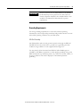
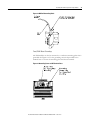
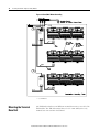
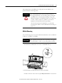
1
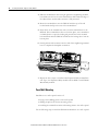
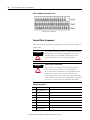
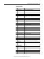
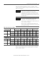
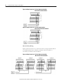
User Guide
Firmware Revision 5
XM-441 Expansion Relay Module
Catalog Numbers 1440- REX00-04RD
Important User Information
Solid-state equipment has operational characteristics differing from those of electromechanical equipment. Safety
Guidelines for the Application, Installation and Maintenance of Solid State Controls (publication SGI-1.1 available from
your local Rockwell Automation sales office or online at http://www.rockwellautomation.com/literature/) describes some
important differences between solid-state equipment and hard-wired electromechanical devices. Because of this difference,
and also because of the wide variety of uses for solid-state equipment, all persons responsible for applying this equipment
must satisfy themselves that each intended application of this equipment is acceptable.
In no event will Rockwell Automation, Inc. be responsible or liable for indirect or consequential damages resulting from
the use or application of this equipment.
The examples and diagrams in this manual are included solely for illustrative purposes. Because of the many variables and
requirements associated with any particular installation, Rockwell Automation, Inc. cannot assume responsibility or
liability for actual use based on the examples and diagrams.
No patent liability is assumed by Rockwell Automation, Inc. with respect to use of information, circuits, equipment, or
software described in this manual.
Reproduction of the contents of this manual, in whole or in part, without written permission of Rockwell Automation,
Inc., is prohibited.
Throughout this manual, when necessary, we use notes to make you aware of safety considerations.
WARNING: Identifies information about practices or circumstances that can cause an explosion in a hazardous
environment, which may lead to personal injury or death, property damage, or economic loss.
ATTENTION: Identifies information about practices or circumstances that can lead to personal injury or death,
property damage, or economic loss. Attentions help you identify a hazard, avoid a hazard, and recognize the
consequence
SHOCK HAZARD: Labels may be on or inside the equipment, for example, a drive or motor, to alert people that
dangerous voltage may be present.
BURN HAZARD: Labels may be on or inside the equipment, for example, a drive or motor, to alert people that
surfaces may reach dangerous temperatures.
IMPORTANT
Identifies information that is critical for successful application and understanding of the product.
Allen-Bradley, Rockwell Automation, and XM are trademarks of Rockwell Automation, Inc.
Trademarks not belonging to Rockwell Automation are property of their respective companies.
3
Safety Approvals
The following information applies when operating this
equipment in hazardous locations.
Informations sur l’utilisation de cet équipement en
environnements dangereux.
Products marked "CL I, DIV 2, GP A, B, C, D" are suitable for use in
Class I Division 2 Groups A, B, C, D, Hazardous Locations and
nonhazardous locations only. Each product is supplied with markings
on the rating nameplate indicating the hazardous location
temperature code. When combining products within a system, the
most adverse temperature code (lowest "T" number) may be used to
help determine the overall temperature code of the system.
Combinations of equipment in your system arfe subject to
investigation by the local Authority Having Jurisdiction at the time of
installation.
Les produits marqués "CL I, DIV 2, GP A, B, C, D" ne conviennent
qu'à une utilisation en environnements de Classe I Division 2
Groupes A, B, C, D dangereux et non dangereux. Chaque produit
est livré avec des marquages sur sa plaque d'identification qui
indiquent le code de température pour les environnements
dangereux. Lorsque plusieurs produits sont combinés dans un
système, le code de température le plus défavorable (code de
température le plus faible) peut être utilisé pour déterminer le
code de température global du système. Les combinaisons
d'équipements dans le système sont sujettes à inspection par les
autorités locales qualifiées au moment de l'installation.
WARNING:
RISQUE D’EXPLOSION
WARNING:
EXPLOSION HAZARD
•Do not disconnect equipment unless power has
been removed or the area is known to be
nonhazardous.
•Do not disconnect connections to this equipment
unless power has been removed or the area is
known to be nonhazardous. Secure any external
connections that mate to this equipment by using
screws, sliding latches, threaded connectors, or
other means provided with this product.
•Substitution of components may impair suitability
for Class I, Division 2.
•If this product contains batteries, they must only be
changed in an area known to be nonhazardous.
IMPORTANT
Model
•Couper le courant ou s'assurer que
l'environnement est classé non dangereux
avant de débrancher l'équipement.
•Couper le courant ou s'assurer que
l'environnement est classé non dangereux
avant de débrancher les connecteurs. Fixer tous
les connecteurs externes reliés à cet
équipement à l'aide de vis, loquets coulissants,
connecteurs filetés ou autres moyens fournis
avec ce produit.
•La substitution de composants peut rendre cet
équipement inadapté à une utilisation en
environnement de Classe I, Division 2.
•S'assurer que l'environnement est classé non
dangereux avant de changer les piles.
Wiring to or from this device, which enters or leaves the system enclosure, must utilize wiring methods suitable for
Class I, Division 2 Hazardous Locations, as appropriate for the installation in accordance with the product drawings as
indicated in the following table.
Catalog Number
Haz Location Drawings*
w/o Barriers
XM-120
1440-VST0201RA
XM-121
1440-VLF0201RA
XM-122
Model
Catalog Number
w/ Barriers
Haz Location Drawings*
w/o Barriers
w/ Barriers
48238-HAZ
48239-HAZ
48295-HAZ
48299-HAZ
XM-320
1440-TPS0201RB
XM-360
1440-TPR0600RE
1440-VSE0201RA
XM-361
1440-TUN0600RE
XM-123
1440-VAD0201RA
XM-361
1440-TTC0600RE
XM-160
1440-VDRS0600RH
XM-440
1440-RMA0004RC
48240-HAZ
N/A
XM-161
1440-VDRS0606RH
XM-441
1440-REX0004RD
48241-HAZ
N/A
XM-162
1440-VDRP0600RH
XM-442
1440-REX0304RG
48642-HAZ
N/A
XM-220
1440-SPD0201RB
48178-HAZ
51263-HAZ
48640-HAZ
48179-HAZ
51264-HAZ
48641-HAZ
* Drawings are available on the included CD
Rockwell Automation Publication GMSI10-UM019C-EN-P - June 2010
4
Rockwell Automation Publication GMSI10-UM019C-EN-P - June 2011
Table of Contents
Chapter 1
Introducing the XM-441 Expansion Relay Module . . . . . . . . . . . . . . . . 7
XM-441 Module Components. . . . . . . . . . . . . . . . . . . . . . . . . . . . . . . . . 8
Using this Manual. . . . . . . . . . . . . . . . . . . . . . . . . . . . . . . . . . . . . . . . . . . 8
Organization. . . . . . . . . . . . . . . . . . . . . . . . . . . . . . . . . . . . . . . . . . . . 9
Document Conventions . . . . . . . . . . . . . . . . . . . . . . . . . . . . . . . . . . 9
Introduction
Chapter 2
Installing the XM-441 Expansion
Relay Module
XM Installation Requirements. . . . . . . . . . . . . . . . . . . . . . . . . . . . . . . . 12
Wiring Requirements . . . . . . . . . . . . . . . . . . . . . . . . . . . . . . . . . . . . 12
Power Requirements . . . . . . . . . . . . . . . . . . . . . . . . . . . . . . . . . . . . 12
Grounding Requirements . . . . . . . . . . . . . . . . . . . . . . . . . . . . . . . . 13
Mounting the Terminal Base Unit. . . . . . . . . . . . . . . . . . . . . . . . . . . . . 16
DIN Rail Mounting . . . . . . . . . . . . . . . . . . . . . . . . . . . . . . . . . . . . . 17
Panel/Wall Mounting . . . . . . . . . . . . . . . . . . . . . . . . . . . . . . . . . . . 18
Connecting Wiring for Your Module . . . . . . . . . . . . . . . . . . . . . . . . . . 19
Terminal Block Assignments. . . . . . . . . . . . . . . . . . . . . . . . . . . . . . 20
Power Supply . . . . . . . . . . . . . . . . . . . . . . . . . . . . . . . . . . . . . . . . . . 22
Connecting the Relays . . . . . . . . . . . . . . . . . . . . . . . . . . . . . . . . . . . 22
Mounting the Module . . . . . . . . . . . . . . . . . . . . . . . . . . . . . . . . . . . . . . 25
Module Indicators . . . . . . . . . . . . . . . . . . . . . . . . . . . . . . . . . . . . . . . . . 26
Appendix A
Specifications
. . . . . . . . . . . . . . . . . . . . . . . . . . . . . . . . . . . . . . . . . . . . . . . . . . . . . . . . . 29
Glossary
. . . . . . . . . . . . . . . . . . . . . . . . . . . . . . . . . . . . . . . . . . . . . . . . . . . . . . . . . 31
Index
. . . . . . . . . . . . . . . . . . . . . . . . . . . . . . . . . . . . . . . . . . . . . . . . . . . . . . . . . 35
5Rockwell Automation Publication GMSI10-UM019C-EN-P - June 2011
6
Table of Contents
Rockwell Automation Publication GMSI10-UM019C-EN-P - June 2011
Chapter
1
Introduction
This chapter provides an overview of the XM-441 Expansion Relay module. It
also discusses the components of the module.
For information about
Introducing the XM-441
Expansion Relay Module
See page
Introducing the XM-441 Expansion Relay Module
7
XM-441 Module Components
8
Using this Manual
8
The XM-441 Expansion Relay module provides an additional four relays to
any XM measurement module or to the XM-440 Master Relay module. It is a
member of the Allen-Bradley™ XM® Series, a family of DIN rail mounted
condition monitoring and protection modules that operate both in stand-alone
applications or integrate with Programmable Logic Controllers (PLCs) and
control system networks.
The XM-441 offers four high power relays suitable for use in almost any
protection application. Up to two Relay Expansion modules may be connected
to the XM-440 Master Relay module, providing an additional four or eight
relays.
The XM-441 is not an intelligent XM module. It must be connected to either
an XM measurement module or the XM-440 Master Relay module in order to
function. In addition, it does not consume a node address on the DeviceNet
bus. The XM-441 simply extends the circuitry of its host module.
No direct configuration of the XM-441 is required. Setup of the XM-441
relays is through its host XM measurement or XM-440 Master Relay module.
7Rockwell Automation Publication GMSI10-UM019C-EN-P - June 2011
8
Introduction
XM-441 Module
Components
The XM-441 consists of a terminal base unit and an instrument module. The
XM-441 Expansion Relay Module and the XM-943 Expansion Relay Terminal
Base are shown below.
Figure 1.1 XM-441 Module Components
EXPANSION RELAY
XM-943 Expansion Relay Module Terminal Base Unit
Cat. No. 1440-TB-D
1440-REX00-04R
D
XM-441 Expansion Relay Module
Cat. No. 1440-REX00-04RD
• XM-943 Expansion Relay Terminal Base Unit - A DIN rail mounted
base unit that provides terminations for all field wiring required by the
XM-441.
• XM-441 Expansion Relay Module - Mounts on the XM-943 terminal
base unit via a keyswitch and a 96-connector. The XM-441 contains four
on-board relays to expand relay capabilities to the XM module to which
it is connected.
IMPORTANT
Using this Manual
The host XM module controls the operation of the relays
in the Expansion Relay module. Refer to the manual for the
specific module for configuration information.
This manual introduces you to the XM-441 Relay Expansion module. It is
intended for anyone who installs or uses the XM-441 Relay Expansion
module.
Rockwell Automation Publication GMSI10-UM019C-EN-P - June 2011
Introduction
9
Organization
To help you navigate through this manual, it is organized in chapters based on
these tasks and topics.
Chapter 1 “Introduction” contains an overview of this manual and the
XM-441 module
Chapter 2 “Installing the XM-441 Expansion Relay Module” describes how to
install, wire, and use the XM-441 module.
Appendix A “Specifications” lists the technical specifications for the XM-441
module.
For definitions of terms used in this Guide, see the Glossary at the end of the
Guide.
Document Conventions
There are several document conventions used in this manual, including the
following:
The XM-441 Expansion Relay module is referred to as XM-441, Expansion
Relay module, device, or module throughout this manual.
TIP
EXAMPLE
A tip indicates additional information which may be
helpful.
This convention presents an example.
Rockwell Automation Publication GMSI10-UM019C-EN-P - June 2011
10
Introduction
Rockwell Automation Publication GMSI10-UM019C-EN-P - June 2011
Chapter
2
Installing the XM-441 Expansion Relay
Module
This chapter discusses how to install and wire the XM-441 Expansion Relay
module. It also describes the module indicators and the basic operations of the
module.
For information about
See page
XM Installation Requirements
12
Mounting the Terminal Base Unit
16
Connecting Wiring for Your Module
19
Mounting the Module
25
Module Indicators
26
ATTENTION
Environment and Enclosure
This equipment is intended for use in a Pollution Degree 2
Industrial environment, in overvoltage Category II applications
(as defined in IED publication 60664–1), at altitudes up to 2000
meters without derating.
This equipment is supplied as “open type” equipment. It must be
mounted within an enclosure that is suitably designed for those
specific environmental conditions that will be present, and
appropriately designed to prevent personal injury resulting from
accessibility to live parts. The interior of the enclosure must be
accessible only by the use of a tool. Subsequent sections of this
publication may contain additional information regarding specific
enclosure type ratings that are required to comply with certain
product safety certifications.
See NEMA Standards publication 250 and IEC publication
60529, as applicable, for explanations of the degrees of
protection provided by different types of enclosures.
11Rockwell Automation Publication GMSI10-UM019C-EN-P - June 2011
12
Installing the XM-441 Expansion Relay Module
XM Installation
Requirements
This section describes wire, power and grounding requirements for an XM
system.
Wiring Requirements
Use solid or stranded wire. All wiring should meet the following requirements:
• 14 to 22 AWG copper conductors without pretreatment; 8 AWG
required for grounding the DIN rail for electromagnetic interference
(emi) purposes
• Recommended strip length 8 millimeters (0.31 inches)
• Minimum insulation rating of 300V
• Soldering the conductor is forbidden
• Wire ferrules can be used with stranded conductors; copper ferrules
recommended
ATTENTION
See the XM Documentation and Configuration Utility CD
for Hazardous Locations installation drawings. The XM
Documentation and Configuration Utility CD is packaged
with the XM modules.
Power Requirements
Before installing your module, calculate the power requirements of all modules
interconnected via their side connectors. The total current draw through the
side connector cannot exceed 3A. Refer to the specifications for the specific
modules for power requirements.
ATTENTION
A separate power connection is necessary if the total
current draw of the interconnecting modules is greater than
3A.
Rockwell Automation Publication GMSI10-UM019C-EN-P - June 2011
Installing the XM-441 Expansion Relay Module
IMPORTANT
13
Power connections are not made directly to the XM-441
module. Rather power is passed via the side connector
from the Expansion Module's host module. Refer to that
module's User Manual for further details on power
requirements.
Grounding Requirements
Use these grounding requirements to ensure safe electrical operating
circumstances, and to help avoid potential emi and ground noise that can cause
unfavorable operating conditions for your XM system.
DIN Rail Grounding
The XM modules make a chassis ground connection through the DIN rail.
The DIN rail must be connected to a ground bus or grounding electrode
conductor using 8 AWG or 1 inch copper braid. See Figure 2.1.
Use zinc-plated, yellow-chromated steel DIN rail (Allen-Bradley part no.
199-DR1 or 199-DR4) or equivalent to assure proper grounding. Using other
DIN rail materials (e.g. aluminum, plastic, etc.), which can corrode, oxidize, or
are poor conductors can result in improper or intermittent platform
grounding.
Rockwell Automation Publication GMSI10-UM019C-EN-P - June 2011
14
Installing the XM-441 Expansion Relay Module
Figure 2.1 XM System DIN Rail Grounding
1
1440-VST02-01RA
DYNAMIC MEASUREMENT
1440-REX00-04RD
EXPANSION RELAY
1440-VST02-01RA
DYNAMIC MEASUREMENT
1440-REX00-04RD
EXPANSION RELAY
Power
Supply
1440-RMA00-04RC
MASTER RELAY
1
1440-REX00-04RD
EXPANSION RELAY
1440-VST02-01RA
DYNAMIC MEASUREMENT
1440-TSP02-01RB
POSITION
1440-REX00-04RD
EXPANSION RELAY
1440-REX00-04RD
EXPANSION RELAY
1440-VST02-01RA
DYNAMIC MEASUREMENT
1440-REX00-04RD
EXPANSION RELAY
Power
Supply
1
Use 14 AWG wire.
The grounding wire can be connected to the DIN rail using a DIN Rail
Grounding Block (Figure 2.2).
Rockwell Automation Publication GMSI10-UM019C-EN-P - June 2011
Installing the XM-441 Expansion Relay Module
15
Figure 2.2 DIN Rail Grounding Block
Panel/Wall Mount Grounding
The XM modules can also be mounted to a conductive mounting plate that is
grounded. See Figure 2.4. Use the grounding screw hole provided on the
terminal base to connect the mounting plate the Chassis terminals.
Figure 2.3 Grounding Screw on XM Terminal Base
Rockwell Automation Publication GMSI10-UM019C-EN-P - June 2011
16
Installing the XM-441 Expansion Relay Module
Figure 2.4 Panel/Wall Mount Grounding
1
Power
Supply
1
Power
Supply
1
Mounting the Terminal
Base Unit
Use 14 AWG wire.
The XM family includes several different terminal base units to serve all of the
XM modules. The XM-943 terminal base, Cat. No. 1440-TB-D, is the only
terminal base unit used with the XM-441.
Rockwell Automation Publication GMSI10-UM019C-EN-P - June 2011
Installing the XM-441 Expansion Relay Module
17
The terminal base can be DIN rail or wall/panel mounted. Refer to the
specific method of mounting below.
ATTENTION
The XM modules make a chassis ground connection
through the DIN rail. Use zinc plated, yellow chromated
steel DIN rail to assure proper grounding. Using other
DIN rail materials (e.g. aluminum, plastic, etc.), which can
corrode, oxidize or are poor conductors can result in
improper or intermittent platform grounding.
You can also mount the terminal base to a grounded
mounting plate. Refer to Panel/Wall Mount Grounding on
page 15.
DIN Rail Mounting
Use the following steps to mount the XM-943 terminal base unit on a DIN rail
(A-B pt no. 199-DR1 or 199-DR4).
IMPORTANT
The XM-943 terminal base unit is mounted to the right of
the XM module to which it is providing additional relays.
1. Position the terminal base on the 35 x 7.5mm DIN rail (A).
Position terminal base at a slight angle and hook over the top of the DIN rail.
2. Make certain the side connector (B) if fully retracted into the base unit.
Rockwell Automation Publication GMSI10-UM019C-EN-P - June 2011
18
Installing the XM-441 Expansion Relay Module
3. Slide the terminal base unit over tight against the neighboring terminal
base. Make sure the hook on the terminal base slides under the edge of
the adjacent base and the side connector is fully retracted.
4. Rotate the terminal base onto the DIN rail with the top of the rail
hooked under the lip on the rear of the terminal base.
5. Press down on the terminal base unit to lock the terminal base on the
DIN rail. If the terminal base does not lock into place, use a screwdriver
or similar device to open the locking tab, press down on the terminal
base until flush with the DIN rail and release the locking tab to lock the
base in place.
6. Gently push the side connector into the side of the neighboring terminal
base to complete the backplane connection.
7. Repeat the above steps to install another Expansion Relay terminal base
unit. Up to two Expansion Relay modules can be added to each XM-440
Master Relay module.
Panel/Wall Mounting
Installation on a wall or panel consists of:
• laying out the drilling points on the wall or panel
• drilling the pilot holes for the mounting screws
• installing the terminal base units and securing them to the wall or panel
Use the following steps to install the XM-943 terminal base on a wall or panel.
Rockwell Automation Publication GMSI10-UM019C-EN-P - June 2011
Installing the XM-441 Expansion Relay Module
19
1. Lay out the required points on the wall/panel as shown in the drilling
dimension drawing below.
Side Connector
2. Drill the necessary holes for the #6 self-tapping mounting screws.
3. Retract the side connector into the base unit. Make sure it is fully
retracted.
4. Position the terminal base unit up tight against the neighboring terminal
base. Make sure the hook on the terminal base slides under the edge of
the terminal base unit.
5. Gently push the side connector into the side of the neighboring terminal
base to complete the backplane connection.
6. Secure the terminal base to the wall with two #6 self-tapping screws.
7. Repeat the above steps to install another Expansion Relay terminal base
unit. Up to two Expansion Relay modules can be added to each XM-440
Master Relay module.
Connecting Wiring for Your
Module
Wiring to the module is made through the terminal base unit on which the
module mounts. The XM-441 is compatible only with the XM-943 terminal
base unit, Cat. No. 1440-TB-D.
Rockwell Automation Publication GMSI10-UM019C-EN-P - June 2011
20
Installing the XM-441 Expansion Relay Module
Figure 2.5 XM-942 Terminal Base Unit
XM-943, Cat. No. 1440-TB-D
Terminal Block Assignments
The terminal block assignments and descriptions for the XM-441 module are
shown below.
ATTENTION
WARNING
The terminal block assignments are different for different
XM modules. The following table applies only to the
XM-441. Refer to the installation instructions for the
specific XM module for its terminal assignments.
EXPLOSION HAZARD
Do not disconnect equipment unless power has been
removed or the area is known to be nonhazardous.
Do not disconnect connections to this equipment unless
power has been removed or the area is known to be
nonhazardous. Secure any external connections that mate
to this equipment by using screws, sliding latches, threaded
connectors, or other means provided with this product.
Terminal Assignments
No.
Name
Description
0
No Connection
1
No Connection
2
No Connection
3
Reserved
4
Relay 1 N.O. 2
Relay #1 Normally Open contact 2
5
Relay 1 N.O. 1
Relay #1 Normally Open contact 1
6
Relay 2 N.O. 2
Relay # 2 Normally Open contact 2
7
No Connection
Rockwell Automation Publication GMSI10-UM019C-EN-P - June 2011
Installing the XM-441 Expansion Relay Module
21
Terminal Assignments
No.
Name
Description
8
Relay 2 N.O. 1
Relay # 2 Normally Open contact 1
9
Relay 3 N.O. 2
Relay #3 Normally Open contact 2
10
No Connection
11
Relay 3 N.O. 1
Relay #3 Normally Open contact 1
12
Relay 4 N.O. 2
Relay #4 Normally Open contact 2
13
Relay 4 N.O. 1
Relay #4 Normally Open contact 1
14
No Connection
15
Chassis
16
No Connection
17
No Connection
18
No Connection
19
No Connection
20
Relay 1 Common 2
Relay #1 Common contact 2
21
Relay 1 Common 1
Relay #1 Common contact 1
22
Relay 2 Common 2
Relay #2 Common contact 2
23
No Connection
24
Relay 2 Common 1
Relay #2 Common contact 1
25
Relay 3 Common 2
Relay #3 Common contact 2
26
No Connection
27
Relay 3 Common 1
Relay #3 Common contact 1
28
Relay 4 Common 2
Relay #4 Common contact 2
29
Relay 4 Common 1
Relay #4 Common contact 1
30
No Connection
31
Chassis
Connection to DIN rail ground spring or panel mounting hole
Connection to DIN rail ground spring or panel mounting hole
DeviceNet bus power input, positive side (red wire)
32
DNet V (+)
33
CAN_High1
34
No Connection
35
No Connection
36
No Connection
37
No Connection
38
Relay 1 N.C. 2
Relay #1 Normally Closed contact 2
39
Relay 1 N.C. 1
Relay #1 Normally Closed contact 1
40
Relay 2 N.C. 2
Relay #2 Normally Closed contact 2
41
No Connection
42
Relay 2 N.C. 1
1
DeviceNet bus connection, high differential (white wire)
Relay #2 Normally Closed contact 1
Rockwell Automation Publication GMSI10-UM019C-EN-P - June 2011
22
Installing the XM-441 Expansion Relay Module
Terminal Assignments
No.
Name
Description
43
Relay 3 N.C. 2
Relay #3 Normally Closed contact 2
44
No Connection
45
Relay 3 N.C. 1
Relay #3 Normally Closed contact 1
46
Relay 4 N.C. 2
Relay #4 Normally Closed contact 2
47
Relay 4 N.C. 1
Relay #4 Normally Closed contact 1
48
No Connection
49
Chassis
Connection to DIN rail ground spring or panel mounting hole
50
DNet V (-)1
DeviceNet bus power input, negative side (black wire)
51
CAN_Low1
DeviceNet bus connection, low differential (blue wire)
1
DeviceNet communication is not used by the XM-943 but DeviceNet connections are available on the terminal
base unit and the side connector.
Power Supply
The host XM module provides power, via the side connector, for the XM-441
module.
Connecting the Relays
The XM-441 has both Normally Open (NO) and Normally Closed (NC) relay
contacts. Normally Open relay contacts close when the control output is
energized. Normally Closed relay contacts open when the control output is
energized.
The alarms associated with the relay and whether the relay is normally
de-energized (non-failsafe) or normally energized (failsafe) depends on the
configuration of the module. Refer to the User Guide for the specific module
for a description of the Relay parameters.
Rockwell Automation Publication GMSI10-UM019C-EN-P - June 2011
Installing the XM-441 Expansion Relay Module
23
There are four double pole double throw relays in the XM-441. All relay
contacts (24 total) are available for wiring at the terminal base unit, as shown in
Table 2.1 on the page 23.
All XM relays are double pole. This means that each relay
has two contacts in which each contact operates
independently but identically. The following information
and illustrations show wiring solutions for both contacts;
although, in many applications it may be necessary to wire
only one contact.
IMPORTANT
The NC/NO terminal descriptions (pages 20–22)
correspond to a de-energized (unpowered) relay.
IMPORTANT
When the relay is configured for non-failsafe operation, the
relay is normally de-energized.
When the relay is configured for failsafe operation, the
relay is normally energized, and the behavior of the NC and
NO terminals is inverted.
Table 2.1 Relay Connections for XM-441
Configured for
Failsafe Operation
Relay 1 Terminals
Relay 2 Terminals
Relay 3 Terminals
Relay 4 Terminals
Nonalarm
Alarm
Wire Contacts
Contact 1
Contact 2 Contact 1
Contact 2
Contact 1 Contact 2 Contact 1
Contact 2
Closed
Opened
COM
21
20
24
22
27
25
29
28
NO
5
4
8
6
11
9
13
12
COM
21
20
24
22
27
25
29
28
NC
39
38
42
40
45
43
47
46
Opened
Closed
Configured for
Non-failsafe Operation
Relay 1 Terminals
Relay 2 Terminals
Relay 3 Terminals
Relay 4 Terminals
Nonalarm
Alarm
Wire Contacts
Contact 1
Contact 2 Contact 1
Contact 2
Contact 1 Contact 2 Contact 1
Contact 2
Closed
Opened
COM
21
20
24
22
27
25
29
28
NC
39
38
42
40
45
43
47
46
COM
21
20
24
22
27
25
29
28
NO
5
4
8
6
11
9
13
12
Opened
Closed
Figures 2.6 and 2.7 illustrate the behavior of the NC and NO terminals when
the relay is wired for failsafe, alarm or nonalarm condition or non-failsafe,
alarm or nonalarm condition.
Rockwell Automation Publication GMSI10-UM019C-EN-P - June 2011
24
Installing the XM-441 Expansion Relay Module
Figure 2.6 Relay Connection - Failsafe, Nonalarm Condition
Non-failsafe, Alarm Condition
Figure 2.7 Relay Connection - Failsafe Alarm Condition
Non-failsafe, Nonalarm Condition
Alternate Relay Wiring
Figures 2.8 and 2.9 show how to wire both ends of a single external indicator
to the XM terminal base for failsafe, nonalarm or alarm condition or
non-failsafe, nonalarm or alarm condition.
Figure 2.8 Relay Connection - Failsafe, Nonalarm Condition
Non-failsafe, Alarm Condition
Rockwell Automation Publication GMSI10-UM019C-EN-P - June 2011
Installing the XM-441 Expansion Relay Module
25
Figure 2.9 Relay Connection - Failsafe, Alarm Condition
Non-failsafe, Alarm Condition
Mounting the Module
The XM-441 mounts on the XM-943 terminal base unit, Cat. No. 1440-TB-D.
You should mount the module after you have connected the wiring on the
terminal base unit.
ATTENTION
The XM-441 is compatible only with the XM-943 terminal
base unit. The keyswitch on the terminal base unit should
be at position 3 for the XM-441.
Do not attempt to install XM-441 modules on other
terminal base units.
Do not change the position of the keyswitch after
wiring the terminal base.
ATTENTION
WARNING
This module is designed so you can remove and insert it
under power. However, when you remove or insert the
module with power applied, I/O attached to the module
can change states due to its input/output signal changing
conditions. Take special care when using this feature.
When you insert or remove the module while power is on,
an electrical can occur. This could cause an explosion in
hazardous location installations. Be sure that power is
removed or the area is nonhazardous before proceeding.
Rockwell Automation Publication GMSI10-UM019C-EN-P - June 2011
26
Installing the XM-441 Expansion Relay Module
1. Make certain the keyswitch (A) on the terminal base unit (C) is at
position 3 as required for the XM-441.
2. Make certain the side connector (B) is pushed all the way to the left. You
cannot install the module unless the connector is fully extended.
3. Make sure that the pins on the bottom of the module are straight so they
will align properly with the connector in the terminal base unit.
4. Position the module (D) with its alignment bar (E) aligned with the
groove (F) on the terminal base.
5. Press firmly and evenly to seat the module in the terminal base unit. The
module is seated when the latching mechanism (G) is locked into the
module.
6. Repeat the above steps to install the next XM-441 module in its terminal
base.
Module Indicators
The XM-441 has a power status indicator (PWR) that is on when power is
applied to the module and an activation status indicator for each relay (four in
all). The indicators are located on top of the module.
Rockwell Automation Publication GMSI10-UM019C-EN-P - June 2011
Installing the XM-441 Expansion Relay Module
Figure 2.10 LED Indicators
1440-REX00-04RD
EXPANSION RELAY
Module Indicators
The following tables describe the states of the LED status indicators.
Power Status Indicator
Color
State
Description
No color
Off
No power applied to the module.
Green
Solid
Power applied to the module.
Relay Indicators (4 in all)
Color
State
Description
Red
Off
On-board relay is not activated.
Solid
On-board relay is activated.
Rockwell Automation Publication GMSI10-UM019C-EN-P - June 2011
27
28
Installing the XM-441 Expansion Relay Module
Rockwell Automation Publication GMSI10-UM019C-EN-P - June 2011
Appendix
A
Specifications
The Appendix lists the technical specifications for the XM-441 module.
XM-441 Technical Specifications
Product Feature
Specification
Communications
Communication interface is via the side
connector between the XM-441 and the XM
module mounted directly to the left of the
XM-441.
Side Connector All XM measurement and relay modules
include side connectors that allow
interconnecting adjacent modules, thereby
simplifying the external wiring
requirements.
The interconnect provides primary power,
DeviceNet communication, and the circuits
necessary to support expansion modules,
such as the XM-441 Expansion Relay
module.
NOTE: DeviceNet protocol, which is not used by
the XM-441, and primary power are passed
through the module’s terminal base to modules
connected on either side of the XM-441.
Indicators
5 LEDs Module Power -green
Relay 1 - red
Relay 2 - red
Relay 3 - red
Relay 4 - red
Relays
Number Four relays, two sets of contacts each DPDT (2 Form C)
Contacts 250V AC, 50/60 Hz, 3 A Resistive
Failsafe Normally energized (failsafe), or
Normally de-energized (non-failsafe)
These features are managed/controlled by
the host XM module. Refer to the applicable
XM module’s specification for details on
these features:
Latching
Time Delay
Voting Logic
Reset
Activation
Rockwell Automation Publication GMSI10-UM019C-EN-P - June 2011
30
Specifications
XM-441 Technical Specifications
Product Feature
Specification
Power
Module 24V DC
Consumption 120mA maximum
Heat Production 2.9 Watts (9.9 BTU/hr) maximum
Environmental
Operating Temperature -20 to +65°C (-4 to +149°F)
Storage Temperature -40 to +85°C (-40 to +185°F)
Relative Humidity 95% non-condensing
All printed circuit boards are conformally coated
in accordance with IPC-A-610C,
Physical
Dimensions Height: 3.8in (97mm)
Width: 3.7in (94mm)
Depth: 3.7in (94mm)
Terminal Screw Torque 7 pound-inches (0.6Nm)
Approvals
(when product or packaging is marked)
UL
UL Listed for Ordinary
Locations
UL
UL Listed for Class I, Division 2
Group A, B, C, and D Hazardous
Locations
CSA
CSA Certified Process Control
Equipment
CSA
CSA Certified Process Control
Equipment for Class I, Division
2 Group A, B, C, and D
Hazardous Locations
EEX*
European Union 94/9/EEC ATEX
Directive, compliant with EN
50021; Potentially Explosive
Atmospheres, Protection “n”
CE*
European Union 89/336/EEC
EMC Directive
C-Tick*
Australian
Radiocommunications Act,
compliant with:
AS/NZS 2064, Industrial
Emissions
* See the Product Certification link at
www.rockwellautomation.com for
Declarations of Conformity, Certificates and
other certification details.
Rockwell Automation Publication GMSI10-UM019C-EN-P - June 2011
Glossary
alarm
An alarm alerts you to a change in a measurement. For example, an alarm can
notify you when the measured vibration level for a machine exceeds a
pre-defined value.
Automatic Device Replacement (ADR)
A means for replacing a malfunctioning device with a new unit, and having the
device configuration data set automatically. The ADR scanner uploads and
stores a device’s configuration. Upon replacing a malfunctioning device with a
new unit (MAC ID 63), the ADR scanner automatically downloads the
configuration data and sets the MAC ID (node address).
baud rate
The baud rate is the speed at which data is transferred on the DeviceNet
network. The available data rates depend on the type of cable and total cable
length used on the network:
Maximum Cable Length
Cable
125K
250K
500K
Thick Trunk Line
500m (1,640ft.)
250m (820ft.)
100m (328ft.)
Thin Trunk Line
100m (328ft.)
100m (328ft.)
100m (328ft.)
Maximum Drop Length
6m (20ft.)
6m (20ft.)
6m (20ft.)
Cumulative Drop Length
156m (512ft.)
78m (256ft.)
39m (128ft.)
The XM measurement modules’ baud rate is automatically set by the bus
master. You must set the XM-440 Relay module baud rate. You set the
XM-440 Relay Master to 125kb, 250kb, 500kb, or Autobaud if another device
on the network has set the baud rate.
bus off
A bus off condition occurs when an abnormal rate of errors is detected on the
Control Area Network (CAN) bus in a device. The bus-off device cannot
receive or transmit messages on the network. This condition is often caused by
corruption of the network data signals due to noise or baud rate mismatch.
Change of State (COS)
DeviceNet communications method in which the XM module sends data
based on detection of any changed value within the input data (alarm or relay
status).
31Rockwell Automation Publication GMSI10-UM019C-EN-P - June 2011
32
Glossary
current configuration
The current configuration is the most recently loaded set of configuration
parameters in the XM module’s memory. When power is cycled, the current
configuration is loaded with either the saved configuration (in EEPROM) or
the factory defaults (if there is no saved configuration). In addition, the current
configuration contains any configuration changes that have been downloaded
to the module since power was applied.
DeviceNet network
A DeviceNet network uses a producer/consumer Controller Area Network
(CAN) to connect devices (for example, XM modules). A DeviceNet network
can support a maximum of 64 devices. Each device is assigned a unique node
address (MAC ID) and transmits data on the network at the same baud rate.
A cable is used to connect devices on the network. It contains both the signal
and power wires. General information about DeviceNet and the DeviceNet
specification are maintained by the Open DeviceNet Vendor’s Association
(ODVA). ODVA is online at http://www.odva.org.
EEPROM
See NVS (Non-Volatile Storage).
Electronic Data Sheet (EDS) Files
EDS files are simple text files that are used by network configuration tools
such as RSNetWorx for DeviceNet to describe products so that you can easily
commission them on a network. EDS files describe a product device type,
revision, and configurable parameters.
Help window
A window that contains help topics that describe the operation of a program.
These topics may include:
•
•
•
•
An explanation of a command.
A description of the controls in a dialog box or property page.
Instructions for a task.
Definition of a term.
MAC ID
See node address.
Rockwell Automation Publication GMSI10-UM019C-EN-P - June 2011
Glossary
33
master device
A device which controls one or more slave devices. The XM-440 Master Relay
module is a master device.
node address
A DeviceNet network can have as many as 64 devices connected to it. Each
device on the network must have a unique node address between 0 and 63.
Node address 63 is the default used by uncommissioned devices. Node
address is sometimes called “MAC ID.”
NVS (Non-Volatile Storage)
NVS is the permanent memory of an XM module. Modules store parameters
and other information in NVS so that they are not lost when the module loses
power (unless Auto Save is disabled). NVS is sometimes called “EEPROM.”
online help
Online help allows you to get help for your program on the computer screen
by pressing F1. The help that appears in the Help window is context sensitive,
which means that the help is related to what you are currently doing in the
program.
Polled
DeviceNet communications method in which the module sends data in
response to a poll request from a master device.
slave device
A device that receives and responds to messages from a Master device but
does not initiate communication. Slave devices include the XM measurement
modules, such as the XM-120 Dynamic Measurement module and the XM-320
Position module.
virtual relay
A virtual relay is a non-physical relay. It has the same capabilities (monitor
alarms, activation delay, change status) as a physical relay only without any
physical or electrical output. The virtual relay provides additional relay status
inputs to a controller, PLC, and an XM440 Master Relay module (firmware
revision 5.0 and later).
XM configuration
XM configuration is a collection of user-defined parameters for XM modules.
Rockwell Automation Publication GMSI10-UM019C-EN-P - June 2011
34
Glossary
XM Serial Configuration Utility Software
XM Serial Configuration Utility software is a tool for monitoring and
configuring XM modules. It can be run on computers running Windows 2000
service pack 2, Windows NT service pack 6, or Windows XP operating
systems.
Rockwell Automation Publication GMSI10-UM019C-EN-P - June 2011
Index
C
P
components
terminal base XM-943 8
XM-441 Expansion Relay module 8
connecting wiring 19
relays 22
terminal base XM-943 19
D
description
terminal base XM-943 8
XM-441 module 8
DIN Rail Grounding Block 14
DIN rail grounding requirements 13
document conventions 9
panel/wall mount grounding requirements 15
power requirements 12
Power Status indicator 27
R
relay contacts
normally closed 22
normally open 22
relay indicators 27
relays, wiring 22
S
specifications 29
T
G
terminal base
mounting on panel/wall 18
terminal base, mounting on DIN rail 16
terminal block assignment 20
grounding requirements 13
DIN rail 13
panel/wall mount 15
I
W
indicators 26
Power Status 27
Relay 27
installation requirements
grounding 13
power 12
wiring 12
introduction 7
wiring
to terminal base 19
wiring connections
relays 22
wiring requirements 12
X
K
keyswitch 25
M
mounting
terminal base unit 16
terminal base unit on panel/walll 18
XM-441 module 25
N
normally closed relay contacts 22
normally open relay contacts 22
XM-441 Expansion Relay Module
components 8
description 8
grounding requirements 13
indicators 26
introduction 7
mounting 25
power requirements 12
specifications 29
wiring requirements 12
XM-943 terminal base
description 8
mounting 16
wiring 19
Rockwell Automation Publication GMSI10-UM019C-EN-P - June 2011
36
Index
Rockwell Automation Publication GMSI10-UM019C-EN-P - June 2011
Rockwell Automation Support
Rockwell Automation provides technical information on the Web to assist you in using its products.
At http://www.rockwellautomation.com/support/, you can find technical manuals, a knowledge base of FAQs, technical and
application notes, sample code and links to software service packs, and a MySupport feature that you can customize to make the
best use of these tools.
For an additional level of technical phone support for installation, configuration, and troubleshooting, we offer TechConnect
support programs. For more information, contact your local distributor or Rockwell Automation representative,
or visit http://www.rockwellautomation.com/support/.
Installation Assistance
If you experience a problem within the first 24 hours of installation, review the information that is contained in this manual.
You can contact Customer Support for initial help in getting your product up and running.
United States or Canada
1.440.646.3434
Outside United States or
Canada
Use the Worldwide Locator at http://www.rockwellautomation.com/support/americas/phone_en.html, or contact
your local Rockwell Automation representative.
New Product Satisfaction Return
Rockwell Automation tests all of its products to ensure that they are fully operational when shipped from the manufacturing facility.
However, if your product is not functioning and needs to be returned, follow these procedures.
United States
Contact your distributor. You must provide a Customer Support case number (call the phone number above to obtain
one) to your distributor to complete the return process.
Outside United States
Please contact your local Rockwell Automation representative for the return procedure.
Documentation Feedback
Your comments will help us serve your documentation needs better. If you have any suggestions on how to improve this document,
complete this form, publication RA-DU002, available at http://www.rockwellautomation.com/literature/.
Rockwell Otomasyon Ticaret A.Ş., Kar Plaza İş Merkezi E Blok Kat:6 34752 İçerenköy, İstanbul, Tel: +90 (216) 5698400
Rockwell Automation Publication GMSI10-UM019C-EN-P - June 2011 38
Supersedes Publication GMSI10-UM019B-EN-P - May 2010
Copyright © 2011 Rockwell Automation, Inc. All rights reserved. Printed in the U.S.A.


![[incr tsdb()]](http://vs1.manualzilla.com/store/data/005780303_1-7064634619abc733efac654e2a82e90d-150x150.png)