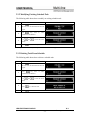
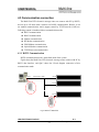
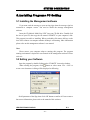
1
USER MANUAL FOR MOVING SIGN Series E2000 LED ELECTRONIC DISPLAY ©All Right Reserved Revision: 1.1 User manual of Multi-Line LED Electronic Message Center Outline Our Multi-line Electronic Message Centers(E200 Moving sign) offer an added level of flexibility to your information display system. They are excellent for detail and multi-tasking requirements. More specialized functions allow you to develop eye-catching messages that attract more customers and promote their organizations more effectively. They are easy to operate and install, can stand-alone as a single electronic display or network as an enterprise wide system of message centers. Based on a modular construction, they allow for a variety of lengths. They can apply to Corporate Communication, Event Listing, Retail Businesses, Medical Offices, Advertising, Waiting areas, Financial Information, Safety Awareness, Announcements and so on. And it brought more convenient for our life. Features We use the latest achievements in LED Electronic Message Centers. ♦ Display English or European characters as well as graphic symbols. ♦ 41 methods of displaying your message (Cyclic, Scroll up, Scroll down, Open to Center, Open from Right, Open from left, etc.) ♦ 9 Fonts, each with regular, bold and wide mode. User can add or modify the fonts. 67 pieces of other European characters ♦ Built-in timer to power on/off during the day ♦ Built-in real time clock. 4 kinds of time and 5 kinds of date formats. Customized time/date format are also available With memory capability of 16k bytes for text, 24k bytes for graphics, max. 250 text files and 250 graphic files. ♦ 8 programmable display speeds ♦ 8 pause periods from 0 to 60 seconds ♦ 3 different buzz sound can be added anywhere within the message. ♦ Count-down/count-up function ♦ Segmented display capability to allow separate control of sections of the display ♦ LED ELECTRONIC DISPLAY Date: 2007/06/15 V1.1 ©All Rights Reserved. -2- Sequencing multiple messages. Built-in scheduler for up to 30 tasks. 3 priority setting enables scheduling by week, month or year. ♦ Duplex function allows user read data from one sign by a PC and copy it to another sign ♦ Up to 128 units can network via RS422 communication ♦ Interface of the managing software can be in multiple languages ♦ Password protection. ♦ Low consumption ♦ Fixing methods: desk, wall or ceiling ♦ Display Real Temperature (optional) ♦ TCP/IP network control (optional) ♦ LED ELECTRONIC DISPLAY Date: 2007/06/15 V1.1 ©All Rights Reserved. -3- Thank you very much that you purchase our product After opens the packing box, please first inspects the fitting according to the detailed list of supply items. If there are something has damaged or lack, please contact your dealer as soon as possible! LED ELECTRONIC DISPLAY Date: 2007/06/15 V1.1 ©All Rights Reserved. -4- Catalog Foreword············································································································································· 8 0. Safety ········································································································································ 9 A: Safety guide ···················································································································9 B: Important Safety Precaution ·························································································10 C: Important Warning ·······································································································11 1. Introduction ··························································································································· 12 1.1 System Outline·····························································································12 1.2 Technical Specification················································································14 1.3 Function Information ··················································································15 1.3.1 Power-on Initialization ·················································································15 1.3.2 Sign ON/OFF Switching ··············································································15 1.3.3 Setting Default File ······················································································16 1.3.4 Display Text ·································································································16 1.3.5 Main Menu···································································································16 2. Function & Operation ·········································································································· 18 2.1 Text Program ·······························································································18 2.1.1 Creating New Text Files ···············································································18 2.1.2 Text File Commands·····················································································18 2.1.3 Edit Text Files ······························································································19 2.1.3.1 Text Editor Interface ············································································19 2.1.3.2 Text Editor Command Keys·································································20 2.1.3.3 Changing Character Font ·····································································20 2.1.3.4 Changing Display Method ···································································21 2.1.3.5 Using Bold Wide and Blink Font ·························································21 2.1.3.6 Changing Character Color ···································································21 2.1.3.7 Changing Message Moving Speed ·······················································22 2.1.3.8 Changing Message Pause Period ·························································22 2.1.3.9 Displaying Time and Date ···································································23 2.1.3.10 Displaying Graphics ··········································································23 2.1.3.11 Starting New Line··············································································23 2.1.3.12 Starting New Page ·············································································23 2.1.3.13 Multi-Window Function ····································································24 2.1.3.14 Including Existing Text Files ·····························································24 2.1.3.15 Changing Line Spacing······································································25 2.1.3.16 Fast Cursor Positioning······································································25 2.1.3.17 Deleting Large Number of Characters················································25 2.1.3.18 Sound with Text·················································································26 2.1.3.19 Inserting International Character························································26 2.1.3.20 Displaying Temperature·····································································26 LED ELECTRONIC DISPLAY Date: 2007/06/15 V1.1 ©All Rights Reserved. -5- 2.1.3.21 Create a Decounter or Incounter ························································26 3. 4. 2.2 Graphics Program ·······················································································27 2.2.1 Creating New Graphics Files········································································27 2.2.2 Graphics File Commands ·············································································27 2.2.3 Edit Graphics File·························································································28 2.2.3.1 Graphics Editor Command Keys··························································28 2.2.3.2 Changing Graphics Size·······································································29 2.2.3.3 Draw and Erase····················································································29 2.2.3.4 Clearing Entire Graphics File ······························································29 2.3 Program Schedule ·······················································································30 2.3.1 Adding New Task To Schedule ·····································································30 2.3.2 Modifying Existing Schedule Task ·······························································32 2.3.3 Deleting Task From Schedule ·······································································32 2.3.4 Enabling/Disabling Schedule Task ·······························································32 2.4 System Setup································································································32 2.4.1 Date & Time·································································································32 2.4.2 Serial ID Address ·························································································32 2.4.3 Baud Rate·····································································································32 2.4.4 Password ······································································································32 2.4.5 Auto Power ON/OFF····················································································32 2.4.6 Sound ON/OF·······························································································32 2.4.7 Backup ON/OF·····························································································32 2.4.8 Recover ON/OF····························································································32 2.4.9 Battery ON/OF ·····························································································32 2.4.10 Auto Demo ON/OF·····················································································32 2.4.11 Make Startup ······························································································32 2.4.12 Clear Startup·······························································································32 2.5 Other Functions···························································································32 2.5.1 Clear Memory ······························································································32 2.5.2 Clear Schedule······························································································32 2.5.3 Clear Graphics Files ·····················································································32 2.5.4 Clear Text Files ····························································································32 2.5.5 View Memory Information ···········································································32 2.5.6 Send Memory ·······························································································32 2.5.7 Backup Memory ···························································································32 2.5.8 Recover Memory··························································································32 Installation ····························································································································· 32 3.1 Overview ······································································································32 3.2 Common mounting method ········································································32 System Connection················································································································ 32 4.1 Data Interface ······························································································32 4.2 Power connection·························································································32 4.3 Communication connection ········································································32 LED ELECTRONIC DISPLAY V1.1 Date: 2007/06/15 ©All Rights Reserved. -6- 4.3.1 4.3.2 4.3.3 4.3.4 4.3.5 4.3.6 4.3.7 4.3.8 RS232 Communication ··································································32 RS422 communication···································································32 Modem communication ·································································32 RF modem communication ····························································32 GSM modem communication ························································32 Optical modem communication ·····················································32 USB communication······································································32 TCP/IP network(LAN) communication··········································32 5. Installing Programs PC Setting··························································································· 32 5.1 Installing the Management software ··························································32 5.2 Setting your Software ··················································································32 6. Maintenance & Troubleshooting························································································· 32 6.1 Maintenance·································································································32 6.2 Cleaning moving sign ··················································································32 6.3 Replacement·································································································32 6.4 Troubleshooting ···························································································32 6.5 Return and Repair·······················································································32 7. Appendix ································································································································ 32 Appendix A: Additional programming tips ······································································32 Appendix B: Listing of color····························································································32 Appendix C: Listing of symbol characters·······································································32 Appendix D: International characters ·············································································32 Appendix E: Remote keys description··············································································32 Appendix F: File Log·······································································································32 8. Statement································································································································ 32 LED ELECTRONIC DISPLAY Date: 2007/06/15 V1.1 ©All Rights Reserved. -7- FOREWORD Foreword The foreword partial has mainly outlined the User Manual of Multi-Line LED Electronic Message Centers. Mainly includes: About this Manual Information feedback About This Manual This Manual is about Multi-Line LED Electronic Message Centers(we often called it as Multi-Line Moving Sign or E2000). It explains the operation, system connection, installation, maintenance and troubleshooting of the display. Reader of the Manual This manual is for the user and the Maintenance of equipment personnel as well as who needs to purchase our product to write. Hope it will bring some help for you! Contents of the manual This manual includes seven parts: Introduction, Function & Operation, Installation, System Connection, Installing programs PC setting, Maintenance and Troubleshooting, Appendix, Statement. Introduction: Description the basic information needed to use the system of Multi-Line Moving Sign. Function & Operation: Description of the function and operation. User must red it before operation. Installation: Gives guidance on installing for moving sign. System Connection: Gives guidance on power cable connection and communication connection for whole system. Installing programs PC setting: Describes installing the program on PC and setting of software. Maintenance & Troubleshooting: Introduce such things as troubleshooting the sign, performing general maintenance. Appendix: List additional thing about this system. Statement: States the copyright. LED ELECTRONIC DISPLAY Date: 2007/06/15 V1.1 ©All Rights Reserved. -8- 0. Safety A: Safety guide Personal protection ☺ Ensure you understand and follow all the safety guidelines, safety instructions, warnings and notes mentioned in this manual. ☺ Wear a hard hat to reduce the risk of personal injury. ☺ Be careful while working with heavy loads. ☺ Mind your fingers while working with heavy loads. Installation personnel The installation must be performed by authorized and qualified technical personnel only. Accredited safety officers must ensure the safety of the site, construction, assembly, connection, use, dismantling, transport etc. of such safety critical systems. Notes Installation should be performed only after you are thoroughly familiar with all of the proper safety checks and installation instructions. Do not modify and/or replace any component. We uses specific materials and manufacturing processes in order to achieve part strength. Consult us for assistance with custom applications. Always follow our installation manual. Contact us if you should have any question regarding the safety of an application. Product care Structural and mounting components should be kept dry, clean and otherwise maintained in a manner consistent with part design. Our products must be used in a manner consistent with their design and inspected on a routine basis for security, wear, deformation, corrosion and any other circumstances that may affect the load handling capability of the part. This product should be operated from the type of power source indicated on the marking label. If you are not sure of power available, consult your dealer or local power company. LED ELECTRONIC DISPLAY Date: 2007/06/15 V1.1 ©All Rights Reserved. -9- SAFETY We recommends inspections at regular intervals for all installations and increasing in frequency for more critical installations. If a part is found to have damage, which may cause a decrease in load capability, the part must be removed for service or replaced immediately. B: Important Safety Precaution Read and understand these instructions. Heed all warnings. Follow all instructions. Personnel must be professional to installing and maintenance. Unplug this product from the electrical outlet before cleaning. Clean only with materials or chemicals that are inert, nonabrasive, noncorrosive and non-marking. Consult the manufacturer for further advice should any doubts exist regarding any cleaning procedure. Do not block ventilation openings. Avoid locations that are subject to direct sunlight (except outdoor models), excessive heat, moisture and dust such as radiators, heat registers, stoves, or other apparatus (including amplifiers) that produce heat. Don’t defeat the safety purpose of the polarized or grounding type plugs/sockets. If the provided sockets/plugs are damaged then replacement of the defective parts must be undertaken immediately. Protect the power/data cables from being walked on or pinched particularly at plugs, convenience receptacles, and the point where they exit from the apparatus. Replace damaged power/data cables immediately. Only use accessories specified by the manufacturer. Disconnect the power to this apparatus during lightning storms or provide suitable additional lightning protection. Unplug this apparatus when unused for long period of time. Refer all servicing to qualified service technicians/personnel. Servicing is required when the apparatus has been damaged in any way, such as power-supply cable or plug is damaged, the apparatus does not working normally, or has been dropped. Use only with systems or peripherals specified by the manufacturer. Use caution during lifting/moving or transporting to avoid damage by possible tipping. Please check truss installation when you mounting the moving sign. Must know the weight for this system before mounting. LED ELECTRONIC DISPLAY Date: 2007/06/15 V1.1 ©All Rights Reserved. - 10 - C: Important Warning Important warning: 1. Danger of electric shock Don’t open or touch! To reduce the danger of electric shock, don’t remove cover. The lightning flash with an arrowhead is intended to tell the user that parts inside the product may cause a danger of electrical shock to persons. 2. Danger of fire To protect against danger of fire by overloading of power cables. Power cable may be connected in parallel. Each power source cable supplying for moving sign should be protected by a circuit breaker or fuses rated. 3. Working environment Temperature: -10 to +40 (Indoor product ); -20 to +60 (Outdoor product ). Humidity: 15%~95% RH. 4. Electro-Static protect LED components used in moving sign are Electro-Static discharge sensitive. To prevent the possibility of destroying LED components do not touch either in operation or while switched off. Servicing or maintaining must be with anti-static instrument(such as ESD hand/heel straps). 5. The equipment must be earthed In order to protect against danger of electric shock, the installation should be properly grounded. We recommend a resistance to ground less than 10 ohms. 6. Power cables The power cables delivered with this system have special properties for safety. They are not user serviceable. If the power cables are damaged, replace only with new ones. Never try to repair a power cable. 7. 8. Data cables The data cables provided with this system have special properties for safety. They are not user serviceable. If the data cables are damaged, replace only with new ones. Never try to repair a data cable. Keep flammable materials away from the equipment (such as curtains). A lot of heat emanated from sign while working. Proper ventilation must be provided. LED ELECTRONIC DISPLAY Date: 2007/06/15 V1.1 ©All Rights Reserved. - 11 - INTRODUCTION 1. Introduction This part has introduced some elementary knowledge and the technical specification of the system. It including following content: System outline Technical specification Function information 1.1 System Outline This system is a Multi-Line LED Electronic Center. It is capable of displaying text and graphics. Messages are stored as files. The system has 16,384 bytes of memory for text files and 24,576 bytes for graphics files. Maximum number of stored text and graphics files is 250 each. Maximum size of a file can reach the entire memory size of the system. Following is something about the system: 16 color combinations: 3 basic colors 5 rainbow colors 8 mixture colors Automatic color rotation (ACL) 9 fonts: SS5, SS7, SF7, SF10, SS16, SF16, TM16, AR16, SMA. Plus all fonts may be BOLD and/or WIDE. 41 display modes: 6 slide modes 6 cover modes 6 roll modes 4 interlace-slide modes 6 interlace-roll modes 4 shutter modes 9 special effect modes AUTO display randomly selects one of available display modes SCROLL display mode for scrolling of large continuous messages ROTATE display mode for rotating of a continuous message 8 message moving speeds 8 pause periods from 0 to 60 seconds 3 kinds of audible beeps during text display LED ELECTRONIC DISPLAY Date: 2007/06/15 V1.1 ©All Rights Reserved. - 12 - 61 special international characters. 4 time and 5 date formats. Custom time/date format also available. 8-characters length file name. Maximum 250 text files and maximum 250 graphic files. Text Memory: 16k bytes 24k bytes graphics memory for 38 colorful graphics (or more) at 160*16 pixels. Flexible size of graphics files. INCLUDE function to call other text files from memory. Multi-WINDOW function allowing for different parts (windows) with different display modes. For example, freeze parts of the display while moving other parts. 30 schedule tasks with 3 priorities enable periodic tasks by week, month or year. User friendly interface and programming via infrared remote control. RS232 or RS422 interface. Modem is supported for long distance communication. Up to 255 signs in one network. Baud rates: 1200, 2400, 4800, 9600, 14400, 19200, 28800 and 57600. Duplex function allowing for reading stored data from the sign by PC and copying data from one sign to another Password security protects the sign from unauthorized access Automatic power ON / OFF schedule Memory Backup feature make the data storage more reliable LED ELECTRONIC DISPLAY Date: 2007/06/15 V1.1 ©All Rights Reserved. - 13 - INTRODUCTION 1.2 Technical Specification Table1 list the technical specification of our multi-line moving sign. Table1 Technical Specification Item Display Element Display Color Average LED lifetime PC Communication Communication Distance Technical Parameters φ 5mm(default), φ 3.75mm or φ 3.0mm LED dot matrixes or LED lamps for indoor use; φ 5 or φ 8 for window brightness. 1. Monochrome: Red, Yellow Green, Amber, Blue, Pure Green, or White etc. 2. RG Multi-color: Red, Green, and Amber, mix color, etc. Total 16 color combinations Over 100,000 hours RS232, RS422, Email, Modem, GSM Modem or Ethernet network. Max.15meters for RS232, 1200meters for RS422 Remote Control IR remote, 62 keys Viewing Angle 160°(H/v) for indoor models, 90°/40° (H/v) for window brightness Working Temperature Working Humidity Power Input -10°C to +40°C 15%-95% RH 100/220VAC , 60Hz/50Hz Memory Retention One year Housing Material Black Powder Coated Aluminum Optional Fittings RS232-RS422 convertor, Modem, RF Modem, GSM Modem, Ethernet adapter LED ELECTRONIC DISPLAY Date: 2007/06/15 V1.1 ©All Rights Reserved. - 14 - 1.3 Function Information This part is descriptive some basal information of operation for the system. 1.3.1 Power-on Initialization Upon power up the system initialization is performed as follows: (1) Install fonts from the font chip, reports NO FONTS CHIP on failure. (2) At initial startup, clear the memory, load default settings and set the real time clock to 1 Jan 2000, 00:00:00. (3) Close unsaved files when abnormal shutdown. Abnormal shutdown will occur when power fails or system halts during remote control programming or serial communication access. (4) Check the system data integrity. Despite the memory being backed up by a battery, it may become corrupted in some unusual circumstances. If the auto recover mode is off, the system will report VERIFY ERROR, and prompt for clearing of the affected data. If the auto recover mode is on, the memory will be recovered from the flash automatically without any prompt. (5) Initialize the modem to automatic answer mode if modem detected. 1.3.2 Sign ON/OFF Switching Switch the sign between ON and OFF States by pressing key. Power up the sign, it will perform the initialization and restore the conditions saved before the last power down. If the sign was in OFF State before last power down, the sign will still keep in OFF State and screen will be cleared; only one dot in the top-right corner will flash slowly. If the sign was in ON State before last power down, the sign will still keep in ON State and it will begin running preprogrammed files. Which file will run first? a. A default file will run when no other task in the schedule meets the running key. condition. Default file can be set with the b. If enable auto running demo, the DEMO file will run if no default file has been set. Otherwise the screen is black. c. Scheduled tasks of the highest priority will run when they meet the running condition. The key can turns the sign ON or OFF. When the sign is at OFF, it consumes low idle power even if it is still connected to the power source. LED ELECTRONIC DISPLAY Date: 2007/06/15 V1.1 ©All Rights Reserved. - 15 - INTRODUCTION 1.3.3 Setting Default File Presses key, input the file name or use and and is possible to input first few characters and then use finished setting. in the listing. Next presses or key to delete a character and Uses to select a file. It to find the file key to cancel the procedure. NOTES: After setting the default file, it may not run immediately. The scheduled tasks will run first. Disable or clear all scheduled tasks if you want to run the default file only. 1.3.4 Display Text Press key to turn OFF the sign. Press key The sign will display red, green and yellow on the entire screen. . 1.3.5 Main Menu Main Menu allows for easy programming of message files, arranging schedule tasks, configuring the sign etc.. Press key to call up the Main Menu. The sign will show the menu items as follows: PROGRAM TEXT Performs all text file operations: NEW, EDIT, RUN, DELETE, RENAME and COPY, view PROPERTY. PROGRAM GRAPHICS Performs all graphics file operations: NEW, EDIT, DELELTE, RENAME and COPY, view PROPERTY. PROGRAM SCHEDULE Performs all schedule operations: NEW, EDIT, DELETE and DISABLE/ENABLE. SETUP Performs system configurations: DATE AND TIME, SERIAL ADDRESS, BAUD RATE, PASSWORD, AUTO ON/OFF SOUND ON/OFF. OTHER Performs all other operations such as: CLEAR MEMORY, CLEAR SCHEDULE, CLEAR GRAPHICS, CLEAR TEXTS, MEMORY info, SEND MEMORY. LED ELECTRONIC DISPLAY Date: 2007/06/15 V1.1 ©All Rights Reserved. - 16 - Press key and to select an item. Available hot keys: Turn OFF the sign Open text file (creates new text file if there’s no existing file) Open graphics file (creates new graphics file if there’s no existing file) Close the main menu and return to the running mode LED ELECTRONIC DISPLAY Date: 2007/06/15 V1.1 ©All Rights Reserved. - 17 - FUNCTION & OPERATION 2. Function & Operation This section includes five parts: Text program Graphics program Program schedule System setup Other functions 2.1 Text Program PROGRAM TEXT when selected, will list text files in the second line of the screen. The first item of the file list will be “- NEW -”, which allows creating a new file. Use and to select a previously programmed text file. The file list is sorted by name, so by pressing the first character key of the name the selection may be key. faster. To select the first item (“NEW”), press 2.1.1 Creating New Text Files The following table shows how to create a new text file. STEP PROCEDURE 1 key to enter the main Press menu. The first menu item PROGRAM TEXT will appear. DISPLAY ON THE SIGN 2 Press key, the first item of file list “NEW” will be selected. The sign will create a new text file. Press 3 for file name, then press to start editing text file (for details, see chapter:2.1.3 EDIT TEXT FILE ) 4 Press key finish the text editing and return to the running mode. 2.1.2 Text File Commands After selecting a text file from the file list press key to display commands or key to select a command. Press key to execute it. menu. Uses Command and its meanings: EDIT RUN DELETE Edit current text file Set current text file as default and return to running mode Delete current text file. The screen will prompt: “DELETE TEXT A, ARE YOU SURE (Y/N)?”. Press “Y” to confirm, “N” to cancel. LED ELECTRONIC DISPLAY Date: 2007/06/15 V1.1 ©All Rights Reserved. - 18 - RENAME COPY PROPERTY Rename current text file Make a copy of current text file View current text file’s property such as size and modify time Available hot keys: Edit the text file Set the text file as default and return to running mode Delete the text file The following table shows how to edit an existing text file “B” (the text file “B” has been already created): PROCEDURE STEP Press 1 DISPLAY ON THE SIGN key to enter the main menu. The first menu item PROGRAM TEXT will appear. 2 3 Press key to select the text file “B” Press key to display the command menu. The first command EDIT will be shown. * 4 Press key to start editing the text file “B”. 5 * Pressing the Press key to finish the text editing and return to the running mode. key will cause the system to go to edit text file “B” immediately after step 2. 2.1.3 Edit Text Files 2.1.3.1 Text Editor Interface insertion mode TEXT uppercases INS CONTROL CAP FILE NAME Keyboard status: The contents of the text file will be displayed in a single line. The CURSOR is always located in the rightmost character of the screen. The file name will be displayed in the beginning of the text file and delimited by the character ‘>’. “CONTROLS” control display methods, fonts, colors and so on. They are often LED ELECTRONIC DISPLAY Date: 2007/06/15 V1.1 ©All Rights Reserved. - 19 - FUNCTION & OPERATION delimited by ‘[’ and ‘]’. The text is displayed in its actual font and color. The current keyboard status is shown in the bottom-left corner of the screen. 2.1.3.2 Text Editor Command Keys Close and save the file, and turn OFF the sign Close and save the file and run it as default Close and save the file and go to main menu Toggle between uppercase and lowercase Toggle between insertion mode and overwriting mode Hide / Show the keyboard status Move cursor left Move cursor right Move cursor to the front page Move cursor to the next page Delete one text character or control character Delete the current page 2.1.3.3 Changing Character Font Press key to insert the text FONT control character. Uses key to select one of the 9 fonts. or The following table list available fonts: FONT DESCRIPTION [SS5] SANS SERIF, 5 pixels height [SS7] SANS SERIF, 7 pixels height (Default) [SF7] SERIF, 7 pixels height [SF10] SERIF, 10 pixels height [SS16] SANS SERIF, 16 pixels height [SF16] SERIF, 16 pixels height [TM16] Times New Roman, 16 pixels height [AR16] Arial, 16 pixels height [SMA] Small Fonts, 8 pixels height LED ELECTRONIC DISPLAY Date: 2007/06/15 V1.1 ©All Rights Reserved. - 20 - 2.1.3.4 Changing Display Method METHOD control is used to change the display methods. key to insert the METHOD control character in the text. The sign Press has 41 display methods (including AUTO, SCROLL, ROTATE…etc). Press to select, or press or press for faster selection. or The table below list available display methods: DESCRIPTION METHOD [AUTO] Randomly selects one of the available display modes. (Default) [IMMED] Immediate display mode [SLIDE] Slide display modes (6 directions) [COVER] Cover display modes (6 directions) [ROLL] Roll display modes (6 directions) [INSLID] Interlace-slide display modes (4 kinds) [INROLL] Interlace-roll display modes (6 kinds) [SHUTT] Shutter display modes (4 kinds) [JUMP] Jump display mode [SNOW] Snow display mode [RANDOM] Random display mode [SHOOT] Shoot display mode [EXPLODE] Explode display mode [TWINKLE] Twinkle display mode [FLASH] Flash display mode [PACMAN] Pac-Man display mode [SCROLL] Scroll display mode, use to scroll a large continuous message [ROTATE] Rotate display mode, use to rotate a large continuous message 2.1.3.5 Using Bold Wide and Blink Font Press the text. Use key to insert the BOLD/WIDE/BLINK control character for or to select between BOLD, WIDE and BLINK. All text between two BOLD/WIDE/BLINK control characters will be displayed as bold/wide/blink font. 2.1.3.6 Changing Character Color Press key to insert the text COLOR control character. Uses key to select one of the color combinations. The following table list available combinations: LED ELECTRONIC DISPLAY Date: 2007/06/15 or V1.1 ©All Rights Reserved. - 21 - FUNCTION & OPERATION COLOR DESCRIPTION [ACL] Auto color, circularly change color when load a new page [RED] Red (Default) [GRN] Green [YEL] Yellow [RB1] Rainbow color 1 [RB2] Rainbow color 2 [RB3] Rainbow color 3 [RB4] Rainbow color 4 [RB5] Rainbow color 5 [MIX1] Mixture color 1 [MIX2] Mixture color 2 [MIX3] Mixture color 3 [MIX4] Mixture color 4 [MIX5] Mixture color 5 [MIX6] Mixture color 6 [MIX7] Mixture color 7 [MIX8] Mixture color 8 2.1.3.7 Changing Message Moving Speed key to insert the SPEED control character. The sign supports 8 Press and to select one of them. [SPEED1] is the lowest speed, speeds. Use and [SPEED8] is the fastest. Default speed is [SPEED5]. 2.1.3.8 Changing Message Pause Period Press key to insert PAUSE control character for the text. Uses key to select one of the available pause periods. PAUSE DESCRIPTION [NO PAU] No pause [PAU 1S] Pause 1 second [PAU 2S] Pause 2 seconds [PAU 3S] Pause 3 seconds [PAU 5S] Pause 5 seconds (Default) [PAU 10S] Pause 10 seconds [PAU 30S] Pause 30 seconds [PAU 60S] Pause 1 minute LED ELECTRONIC DISPLAY Date: 2007/06/15 V1.1 ©All Rights Reserved. - 22 - or 2.1.3.9 Displaying Time and Date Press key while in the edit text file mode. The system will display the time insertion menu as in the following table: MENU ITEM DESCRIPTION INSERT TIME Insert time, 4 formats: 23:59 (Default); 23:59:59; 12:59 AM; 12:59:59 AM INSERT DATE Insert date, 5 formats: 1 Jan 2000 (Default); Jan 1, 2000; 10/1/2000; 1/10/2000; 2000.1.10 INSERT HOUR-24 Insert hour in 24-hour mode INSERT HOUR-12 Insert hour in 12-hour mode INSERT MINUTE Insert minute INSERT SECOND Insert second INSERT AM/PM Insert AM/PM, 4 formats: e.g. AM (Default); A; am; a INSERT WEEK Insert day of week, 4 formats: e.g. Mon (Default); Monday; MON; MONDAY INSERT DAY Insert day of month INSERT MONTH Insert month, 5 formats: e.g. Jan (Default); January; 1; JAN; JANUARY INSERT YEAR Insert year, 2 formats: e.g. 2000; 00 Use or key to select the time element, then press key to key to cancel. insert it, or press or key to change the time After inserting the TIME control, uses element format. 2.1.3.10 Displaying Graphics Note: A graphics file must be created before it can be displayed. Please refer to Chapter 2.2 for details. Press key while in the editing mode. The system will prompt to input the graphics file name: Input the file name or use or keys to select a file. Then press key to cancel. key to insert the selected graphics file, or press 2.1.3.11 Starting New Line In the text edit mode press key to insert the NEWLINE control character ( ) in order to start a new line. 2.1.3.12 Starting New Page In the text editing mode press key to insert the NEWPAGE control character (---PAGE---) in order to start a new page. LED ELECTRONIC DISPLAY Date: 2007/06/15 V1.1 ©All Rights Reserved. - 23 - FUNCTION & OPERATION 2.1.3.13 Multi-Window Function This function allows to display a message in a selected screen area (window) and to align that message within the window by using WINDOW control functions. key while in the text edit mode. The screen will display a blinking Press box indicating the current window border. The coordinates for the top left corner, width and height of the window will be displayed in the center of the screen. Use the direction keys: to move the left and the top border of the window. Hold the key down while pressing one of the direction keys to move the right and the bottom border of the or in combination with key may be window. Keys used to modify the window box faster. Presses or key to save the window size and position. The WINDOW control character will be automatically inserted in the text. Pressing key will modify the window box again. Pressing and key will select the text alignment mode of the window as listed below: WINDOW TEXT ALIGNMENT T] Left align and top align [ C T] Center align and top align [ R T] Right align and top align [ L M] Left align and middle align [ C M] Center align and middle align (Default) [ R M] Right align and middle align [ L B] Left align and bottom align [ C B] Center align and bottom align [ R B] Right align and bottom align [ L 2.1.3.14 Including Existing Text Files Use this function to display a text file previously stored in the memory. Press key while in the text editing mode. The system will prompt for input of the filename of the text to be included: LED ELECTRONIC DISPLAY Date: 2007/06/15 V1.1 ©All Rights Reserved. - 24 - Input the file name or use or to select one from the list. Then press key to insert, or press key to cancel. INCLUDE control character will be displayed as [I: filename]. NOTES: The maximum depth of INCLUDE function is limited to 20. Cross-Including is not allowed. 2.1.3.15 Changing Line Spacing Press key to insert the VSPACE control character that allows control the line spacing. The default line spacing is [VS 0]. In this setting the system will leave 1 pixel space between two adjacent lines wherever possible. When [VS 1-15] is selected, the line space will be set from 1 to15 pixels. The VSPACE control character must be inserted in the beginning of a text line. Press key to select line spacing from [VS 0] to [VS 15]. 2.1.3.16 Fast Cursor Positioning Press key while in the text editing mode. The system will display the or keys to select a menu item as listed “GO TO” menu. Use below. Press to move the cursor to the selected position. MENU ITEM GO TO FILE BEGINNING GO TO END OF FILE GO TO PREV CONTROL GO TO NEXT CONTROL DESCRIPTION Move cursor to the file beginning Move cursor to the end of file Move cursor to the previous control character Move cursor to the next control character 2.1.3.17 Deleting Large Number of Characters Press key while in the text editing mode. The system will display the or keys to select a menu item as “CLEAR” menu. Use listed below. Press to execute the selected instruction. LED ELECTRONIC DISPLAY Date: 2007/06/15 V1.1 ©All Rights Reserved. - 25 - FUNCTION & OPERATION DESCRIPTION MENUITEM CLEAR ALL THIS FILE CLEAR TO FILE BEGINNING CLEAR TO END OF FILE CLEAR TO PREV CONTROL CLEAR TO NEXT CONTROL Delete all characters in the file Delete all characters from the cursor position to the file beginning Delete all characters from the cursor position to the file end Delete characters from the cursor position to the previous control character (not including the control character). Delete characters from the cursor position to the next control character (not including the control character). 2.1.3.18 Sound with Text Press key while in the text editing mode to insert the SOUND control and to select one of the 3 beep sounds: [BEEP1], character. Use [BEEP2] or [BEEP3]. The selected sound will be integrated with the edited text. 2.1.3.19 Inserting International Character While in the text editing mode, first input one of the characters from the left column as in the table below, then press or key to select an international character. For example: to input the character ‘€’, the character ‘$’ must be input first, then press key six times or press key once. Remark: Appendix D list the international character. 2.1.3.20 Displaying Temperature key to insert the TEMPERATURE control character to display Press temperature in the text file. Three formats temperature are available: Centigrade (°C), Fahrenheit (°F) and Kelvin (K), use or to select them. NOTES: This feature is avalable only for the sign that has installed temperature sensor. 2.1.3.21 Create a Decounter or Incounter We often use a decounter to wait for an important moment such as Year 2K, World Cup 2002, etc. We often use an incounter to count the safty running days, etc. You can create a decounter or incounter like this: Press when editing text file, a menu will appear: ADD DECOUNTER IN DAYS ADD DECOUNTER IN HOURS ADD DECOUNTER IN MINUTES ADD DECOUNTER IN SECONDS ADD INCOUNTER IN DAYS ADD INCOUNTER IN HOURS ADD INCOUNTER IN MINUTES ADD INCOUNTER IN SECONDS the result number is days to the given time the result number is hours to the given time the result number is minutes to the given time the result number is seconds to the given time the result number is days from the given time the result number is hours from the given time the result number is minutes from the given time the result number is seconds from the given time LED ELECTRONIC DISPLAY Date: 2007/06/15 V1.1 ©All Rights Reserved. - 26 - to continue, the screen will display: Choose the item you need, then press Set the time that will be count down to or count up from and press , a decounter or incounter now has been created. The decounter or incounnter add in text will display in a number from 0 to 65535. Larger number will display as ‘------’. The decounter will stop at 0 when the given time passed, and the incounter will display 0 even the time has not started. 2.2 Graphics Program Graphics programming is similar to that of text programming. 2.2.1 Creating New Graphics Files Follow the table below to create a new graphics file. Example filename: “A”: STEP PROCEDURE Press 1 DISLAY ON THE SIGN key to enter the main menu. The first menu item PROGRAM TEXT will appear. 2 Press Press 3 key to select the menu item “PROGRAM GRAPHICS”. key, the first item of file list “NEW ” will be created as a new graphics file. Press 4 for file name, then press to start editing. (For details, see chapter 3.3 EDIT THE TEXT FILE ) 5 Press key to finish the graphics editing and return to the running mode. 2.2.2 Graphics File Commands After selecting a graphics file from the file list, press key to display the or key to select a command. Press key to command menu. Uses execute it. LED ELECTRONIC DISPLAY Date: 2007/06/15 V1.1 ©All Rights Reserved. - 27 - FUNCTION & OPERATION Command and its meanings: EDIT Edit current graphics file DELETE Delete current graphics file. The screen will prompt “DELETE GRAPH A, ARE YOU SURE (Y/N)?”, press “Y” to confirm, “N” to cancel. RENAME Rename current graphics file COPY Make a copy of current graphics file PROPERTY View current graphics file’s property such as size and modification time. Available hot keys: Edit the graphics file Delete the graphics file The following table shows how to edit existing graphics file “B” (created previously): STEP PROCEDURE Press 1 DISPLAY ON THE SIGN key to enter the main menu. The first menu item PROGRAM TEXT will appear. 2 3 4 5 6 * Press Press key to select the menu item PROGRAM GRAPHICS. Press key to select graphics file “B”. Press key to display the command menu. The first command EDIT is shown. Press key to start editing graphics file “B”. Press key to finish graphics editing and return to the running mode. key to go to edit graphics file “B” immediately after step 3. 2.2.3 Edit Graphics File 2.2.3.1 Graphics Editor Command Keys Close and save the file and turn OFF the sign Close and save the file and return to running mode Close and save the file and go to main menu Move cursor left and up Move cursor up Move cursor right and up LED ELECTRONIC DISPLAY Date: 2007/06/15 V1.1 ©All Rights Reserved. - 28 - Move cursor left Move cursor right Move cursor left and down Move cursor down Move cursor right and down Toggle paint mode Select pen color Select pen color Toggle one point drawing 2.2.3.2 Changing Graphics Size In graphics editing mode, press Press key or or key to changes graphics size. to select “HEIGHT” or “WIDTH” for changing the size. Press key or to modify the value or or or to complete. to modify fast. Finally press It is also possible to adjust the graphics size by using the combined keys: key plus one of the cursor-moving keys . 2.2.3.3 Draw and Erase Press key to toggle the paint mode on/off. Use or key to select color, move the cursor, then you can draw a line, which follow the track of cursor. To erase the line move the cursor along the line once again (keep paint mode on, do not change cursor color). The line will be erased. The key is used to draw or erase one dot. 2.2.3.4 Clearing Entire Graphics File In graphics editing mode, press will prompt as shown below: key to clear the entire graphic. The screen Press “Y” to confirm, “N” to cancel. LED ELECTRONIC DISPLAY Date: 2007/06/15 V1.1 ©All Rights Reserved. - 29 - FUNCTION & OPERATION 2.3 Program Schedule PROGRAM SCHEDULE is the third item in the main menu. If no task exists in the schedule, the second line will display “- NEW -” prompting to create a new task. and key to select If there are some has programmed tasks already, use them. 2.3.1 Adding New Task To Schedule The following table shows how to create a new schedule task: STEP PROCEDURE Press 1 DISPLAY ON THE SIGN key to enter the main menu. The first menu item PROGRAM TEXT will appear. 2 Press key twice to select the “PROGRAM SCHEDULE”. 3 Press key to start adding new task. The following 7 steps are needed to create a new schedule task: Step 1 Input the text file name that will be run in task: Uses or key to select one, then press Step 2 Set the START DATE of the task: key to continue. The date format must be D-M-Y (date-month-year). Uses or key to to to modify, then press move the cursor, and press number keys from key to continue. If the year is set to 0, the year will be ignored and the task will start each year. For example, if START DATE is set to 01-05-0000, the task will start on May 1st of each year. LED ELECTRONIC DISPLAY Date: 2007/06/15 V1.1 ©All Rights Reserved. - 30 - If both, the year and the month are set to 0, the task will start each month. For example: START DATE 01-00-0000 means the task will start on the first day of each month. If all of the year, month and day are set to 0, the task will be run always. This is also the default setting of the system. Step 3 Set the END DATE of the task: The date format must be D-M-Y (date-month-year). Use or to move the cursor, and press number keys from to to modify, then press key to continue. If the year is set to 0, the year will be ignored and the task will end each year. For example, if END DATE is set to 31-10-0000, the task will end after 31 Oct of each year. If both the year and the month are set to 0, the task will end each month. For example, END DATE 10-00-0000 means the task will end after the 10th each month. If all of the year, month and day are set to 0, the task will never stop. This is also the system default setting. Step 4 Set the START TIME of the task: The time format must be hh: mm (hour: minute). Uses move the cursor, and press number keys from to key to continue. The default START TIME is 00:00. Step 5 Set the END TIME of the task: The time format must be hh: mm (hour: minute). Uses LED ELECTRONIC DISPLAY Date: 2007/06/15 or key to to modify, then press or key to V1.1 ©All Rights Reserved. - 31 - FUNCTION & OPERATION move the cursor, and press number keys from to key to continue. The default END TIME is 23:59. Stet 6 to modify, then press Set the running days of the week: Uses or key to move the cursor, and press or key to modify, then press key to continue. The default setting is run from Monday to Sunday (run on each day of the week). Step 7 Set the priority of the task: Uses or key to modify, then press key to finish adding new task. The three levels of priorities are: NORMAL, LOW and HIGH. key at any time. The new task This procedure can be canceled by pressing will be displayed on the task list immediately after these 7 steps (In the second line of the screen). LED ELECTRONIC DISPLAY Date: 2007/06/15 V1.1 ©All Rights Reserved. - 32 - 2.3.2 Modifying Existing Schedule Task The following table shows how to modify an existing schedule task: STEP PROCEDURE Press 1 DISPLAY ON THE SIGN key to enter the main menu. The first menu item PROGRAM TEXT will appear. 2 3 4 key Pres twice to select “PROGRAM SCHEDULE”. Use and to choose the task to modify. Press key start to modify the task. 7 steps are needed to modify the task, please refer to section 2.3.1 Adding New Task To Schedule 2.3.3 Deleting Task From Schedule The following table shows how to delete a schedule task. STEP PROCEDURE Press 1 DISPLAY ON THE SIGN key to enter the main menu. The first menu item PROGRAM TEXT will appear. 2 3 key Press twice to select “PROGRAM SCHEDULE”. Use and to select the task to delete. 4 Press key to delete the task. 5 Press to confirm deletion. LED ELECTRONIC DISPLAY Date: 2007/06/15 V1.1 ©All Rights Reserved. - 33 - FUNCTION & OPERATION 2.3.4 Enabling/Disabling Schedule Task The following table shows how to enable or disable a schedule task: STEP PROCEDURE key to enter the main menu. Press 1 DISPLAY ON THE SIGN The first menu item PROGRAM TEXT will appear. 2 3 twice to select “PROGRAM SCHEDULE”. and Use to select the task to enable/disable. Press 4 key Press ‘ key to disable the task. Symbol ’ indicates that the task has been disabled. key again to enable the task. Press 5 Symbol ‘ ’ indicates that the task has been enabled. 6 Press key then return to the running mode. 2.4 System Setup When selected, the setup menu command will be displayed in the second line of the screen. The setup menu commands: DATE & TIME Set current date and time SERIAL ADDRESS Set serial address BAUD RATE Set baud rate PASSWORD Set password AUTO ON/OFF Set automatic power on/off SOUND OFF/ON Toggle off/on the sound function AUTO BACKUP ON/OFF Toggle on/off the automatic backup memory mode AUTO RECOVER ON/OFF Toggle on/off the automatic recover memory mode BATTERY ON/OFF Toggle on/off the battery backup function AUTO DEMO ON/OFF Toggle on/off the automatic running demo function MAKE STARTUP Make the graphic file name “STARTUP” as startup picture CLEAR STARTUP Press key and Clear the startup picture to select the setup menu item, then press key LED ELECTRONIC DISPLAY Date: 2007/06/15 V1.1 ©All Rights Reserved. - 34 - to perform the selected function. Clearing memory or deleting graphic file “STARTUP” will not affect the system setup. 2.4.1 Date & Time Select DATE & TIME from SETUP to adjust the real time clock. The screen will display: Press key or to move the cursor, press key and to modify, then press key or to finish. The real time clock will be set to 01 Jan 2000, 00:00:00 when it runs for the first time. 2.4.2 Serial ID Address The serial address is a number from 1 to 255 that is used to identify the sign in the network. Select SERIAL ADDRESS from the SETUP to set the sign address. The screen will display: Press number keys from to to delete one character. Press key The default serial address is set to 1. for the serial address, or press key or when done. 2.4.3 Baud Rate Select BAUD RATE from the SETUP to set the baud rate of the serial communication. The screen will display: LED ELECTRONIC DISPLAY Date: 2007/06/15 V1.1 ©All Rights Reserved. - 35 - FUNCTION & OPERATION Press key finished. and key to changed. Then press key or to The default baud rate is 9600. Available baud rates are: 1200, 2400, 4800, 9600, 14400, 19200, 28800, and 57600. 2.4.4 Password Select PASSWORD from the SETUP to set the password. The screen will display: Enter the password and then press password again: key. The system will prompt to enter the Retype the password and press key. Now the password has been changed, and password protection function will be enabled automatically. The password protection will be disabled when it is set to null. Password is needed when using key to enter the main menu in password protection mode. Input the password key. and press NOTES: Remember or record the password! If the password gets lost, in order to regain access to the system, disconnect the sign and power supply, open the case and connect the SW2 on the main board to ground then power up the sign. 2.4.5 Auto Power ON/OFF Select AUTO ON/OFF from SETUP to activate or deactivate automatic power ON feature. The default setting is: Manual ON/OFF. Use key or to choose the desired setting, press key or to toggle MANUAL/AUTO. Set the Start time for the AUTO mode (default is 00:00, and to select between HH and MM. Use in HH:MM format). Use key and to modify time, press key to complete. key 2.4.6 Sound ON/OF Select SOUND ON/OFF from the SETUP to enable/disable the sound function. Default is ON. LED ELECTRONIC DISPLAY Date: 2007/06/15 V1.1 ©All Rights Reserved. - 36 - 2.4.7 Backup ON/OF Turn on/off the auto backup mode. Under auto backup mode, memory will be backup automatically when the memory content has been changed. Auto backup occur when the memory has been changed and the sign has been running for 10 minutes. Manually backup is necessary if the sign is often moved such as which install on a bus. Default is OFF. 2.4.8 Recover ON/OF Turn on/off the auto recover mode. Under auto backup mode, memory will be recovered automatically when the memory is found damaged. Otherwise, you must press or to confirm the clearing of the affected data. Auto recover mode is the best choice when the sign connect to PC. Default is ON. 2.4.9 Battery ON/OF Turn on/off the battery backup function. When the battery backup is on, memory content can keep for about 3 months without power supply. If you make sure that you don’t need to keep the memory content, for example, you use a PC software to control the display at real-time, you can disable this function. Default is ON. 2.4.10 Auto Demo ON/OF Turn on/off the auto running demo function. When auto running demo function is on, the system will run the DEMO file automatically when no scheduled task is running and no default file is set. The DEMO file is use to demonstrate the high preferment features of this product. Default is ON 2.4.11 Make Startup Make the graphic file name “STARTUP” as startup picture. User must prepare a graphic file name with “STARTUP” first. This picture will be displayed on the next time the power is on. 2.4.12 Clear Startup Clear the startup picture. Graphic file “STARTUP” will not be deleted by this function. Default startup screen will be displayed on the next time the power is on. 2.5 Other Functions When selected, the OTHER commands will be displayed in the second line of the screen. LED ELECTRONIC DISPLAY Date: 2007/06/15 V1.1 ©All Rights Reserved. - 37 - FUNCTION & OPERATION CLEAR MEMORY Clear all memory CLEAR SCHEDULE Clear the schedule CLEAR GRAPHICS Clear all graphics files CLEAR TEXTS Clear all text files MEMORY INFO View memory information SEND MEMORY Send out all memory contents through serial communication to other signs. If you execute this command, the memory contents of all signs in the same net will become identical BACKUP MEMORY Backup the memory to the flash memory. RECOVER MEMORY Recover the memory from the flash memory Note: To send memory contents to other signs, the baud rates of all signs must be the same. Press key execute it. and to select a command, and press key 2.5.1 Clear Memory All text and graphics files will be deleted, and the schedule will be cleared. The setup will not be affected. 2.5.2 Clear Schedule All tasks in the schedule will be deleted. 2.5.3 Clear Graphics Files All graphics files will be deleted. 2.5.4 Clear Text Files All text files will be deleted. 2.5.5 View Memory Information The system will display the text memory information first: Then the graphics memory information: LED ELECTRONIC DISPLAY Date: 2007/06/15 V1.1 ©All Rights Reserved. - 38 - to 2.5.6 Send Memory The SEND MEMORY command can perform the following functions: 1 Send out the “Clear Memory” command to other signs; 2 Send out all graphics files to other signs; 3 Send out all text files to other signs; 4 Send out the schedule to other signs; 5 Send out the “Set default Running File” command to other signs. 2.5.7 Backup Memory You should often backup the memory to avoid unforeseen data lost. The memory is battery powered and can be kept for only three months without power. The shaking of the sign during transportation may also damage the memory data. You can setup the sign to automatic backup mode. 2.5.8 Recover Memory The memory will be recovered automatically when it is damaged. You can recover the memory manually by this command too. You can setup the sign to automatic recover mode. Refer to Chapter 5 for auto recover mode. LED ELECTRONIC DISPLAY Date: 2007/06/15 V1.1 ©All Rights Reserved. - 39 - INSTALLATION 3. Installation 3.1 Overview Because every installation site is unique, there is no standard method of mounting. As manufacture of LED display, we don’t supply support structure, we can only provide recommending for the support structure design. It is customer’s responsibility to ensure that the structure and mounting hardware are able of supporting the Screen, and according with local laws. Support structure design depends on the mounting methods, screen size and its weight. The structure design is critical and should be done only by a qualified individual and organization. The following must be considered first before installation: Design support structure and groundwork; calculate carefully the needed strength according to local codes; especially note the wind load and the issue of Seismic Zone. For the reason of heat dissipation, the waterproof of the back of LED module is IP45; consider if any added shield needed for more protection. If LED Screen is enclosed in an enclosure or casing, air-conditions are needed for cooling when the environment temperature reach 30 oC. Keep enough space for maintains. Prepare for routing power lines and fiber connection. If it is used in outdoor, it is best to route 4 fiber cables. Two are used for data transmitting and the other two are saved for spares. It is doubtless to route power lines and fiber cables in two separate conduits. Grounding consideration, we recommend grounding resistance must be less than 10 ohms. The relations of the screen body size with the distance of installing. The screen body size and the viewing distance should have the suitable proportion relations. The ordinary circumstances viewing distance may take the screen body opposite angle line length 2~20 double, and the effect is better when the viewing distance is in 6~10 doubles. The angle of installing: When the screen body installs, should pay attention to the direction of LED element's light. When the screen body installs at highly, should make the screen body to maintain the certain inclination angle, that in order to causes the direction of shines direct to best viewing position. LED ELECTRONIC DISPLAY Date: 2007/06/15 V1.1 ©All Rights Reserved. - 40 - When the screen body installed, we should pay attention to the influence of outside electromagnetic radiation to the displays. 3.2 Common mounting method The shape and size of Multi-Line LED electronic message center are different; the use of them is diverse and the method of mounting is most changeful. There isn’t a unification standard of the mounting. Following we introduced several commonly used method of mounting. 1) Hang type Hang type include two types. One is hanging up at the ceiling or other truss (fig2.1a shows). The LED moving sign is hanging up at ceiling or truss by the bracket. Another is hanging on wall (fig2.1b shows). The LED moving sign is mounting on wall by the bracket. 2) Swing type Swing type is an especial of hang type. This method is hanging moving sign at wall by a bracket too. But the bracket have a suspend arm for Swing. Fig2.4 shows. 3) Desktop installation This method must design a pedestal to support the LED moving sign. And the LED moving sign is installed on the pedestal. Fig2.2 shows it. 4) Movable structure This method is base on desktop installation. It is different form desktop installation there are some wheels on the pedestal. So it can move easily. Fig2.3 shows it. 5) Insert type Insert type is a method that the moving sign is inserted in wall or other object. Fig2.5 shows it. This method is always using for looking more beautiful. Ceiling Ceiling Bracket Bracket Bracket Bracket Wall Wall Moving sign Moving sign Moving sign Face Moving sign Face Side Fig2.1 a Side Fig2.1 b Fig2.1 Hang type LED ELECTRONIC DISPLAY Date: 2007/06/15 V1.1 ©All Rights Reserved. - 41 - INSTALLATION Moving sign Moving sign Moving sign Moving sign Pedestal Pedestal Pedestal Pedestal Face Side Face Fig 2.2 Desktop installation Wheel Side Fig 2.3 Movable structure Suspend arm Wall Wall Wall Wall Moving sign Moving sign Face Open Side Close Fig 2.5 Insert type Fig 2.4 Swing type Above mentioned method is several commonly used method of mounting. The hang type is the most simply. And its realization is easily. The swing type is based on the hang type, and more complex than hang type. This method can open or close according as your circs. If the place of installation is far form wall or ceiling and the moving sign is big, you can use the desktop installation. If moving sign needs move frequently should use movable structure. In somewhere such as hospital, company, public etc using Moving-Sign for sign. There usually adopt the insert type for beautiful. Certainly, there are many other methods of mounting. We impossibility introduce all methods. User can choose an appropriate method of mounting according as your idiographic circs. Remark: All these methods are must think the weight of moving sign at first. User must make sure the backstop can support the weight of the display while mounting it. LED ELECTRONIC DISPLAY Date: 2007/06/15 V1.1 ©All Rights Reserved. - 42 - 4. System Connection There are two parts work of connection in the system: power cable connection and signal/data cable connection for system. Before connect you should read the data interface of this system. 4.1 Data Interface Multi-line Moving Sign support PC control and TCP/IP network control. There should used RS232 cable or RS422 cable. In general, the connecter of cable is DB-9 interface. Following fig shows DB-9 connecter. Male Female Fig4.1 DB-9 connecter Fig4.2 Pin arrange LED ELECTRONIC DISPLAY Date: 2007/06/15 V1.1 ©All Rights Reserved. - 43 - SYSTEM CONNECTION 4.2 Power connection The power cables connection for outside are very simply. There need have electrical outlet (a Plug AC female) near the moving sign installed. User only need insert the plug male on the plug AC female. The plug male is connected with LED moving sign by a power cable from the power input port on cabinet. The plug AC female is form power source. Following fig shows the power cable connection. Plug male Plug AC female Moving Sign From power source Fig4.3 Power connection LED ELECTRONIC DISPLAY Date: 2007/06/15 V1.1 ©All Rights Reserved. - 44 - 4.3 Communication connection The Multi-Line LED electronic message center can connect with PC by RS232, and can up to 128 units made a network via RS422 communication. Besides, it can use modem communication. And it support control by TCP/IP network (LAN) too. Following content is introduced these communication modes: RS232 communication RS422 communication Modem communication RF Modem communication GSM Modem communication Optical Modem communication TCP/IP network communication 4.3.1 RS232 Communication RS232 communication mode is the default mode of the system. Fig4.4 shows the Multi-Line LED electronic message center connect with PC by RS232 data interface, and fig4.5 shows the Circuit diagram connection of this communication mode. RS232 Cable length < 200m RS232 RS232 COM1 or COM2 RS232 DB9 Fig4.4 RS232 Connection LED ELECTRONIC DISPLAY Date: 2007/06/15 V1.1 ©All Rights Reserved. - 45 - SYSTEM CONNECTION SW1 1 2 3 OFF/ON 2 RxD 3 TxD SW2 1 2 3 422/232 JP8 Cable length < 200m 2 TxD 3 RxD 5 GND 2 4 6 8 10 1 3 5 7 9 5 GND 232_COMM COM1 or COM2 DB9 CPU board (MTP_M??) Address: 001 SW1 1 2 3 OFF/ON Remark: 1. Cable length must less 200 meter. 2. The default mode is RS232. 3. Some PC’s RS232 Data interface can’t driver so many LED displays. 4. SW2: jumper foe select RS232 or RS422, this mode select RS232 (2, 3). SW2 1 2 3 422/232 JP8 2 4 6 8 10 1 3 5 7 9 2 TxD 3 RxD 5 GND 232_COMM DB9 CPU board (MTP_M??) Address: 002 SW1 1 2 3 OFF/ON SW2 1 2 3 422/232 JP8 1 3 5 7 9 2 TxD 3 RxD 5 GND 2 4 6 8 10 232_COMM DB9 CPU board (MTP_M??) Address: N (N 15) < Fig4.5 Circuit diagram of RS232 connection LED ELECTRONIC DISPLAY Date: 2007/06/15 V1.1 ©All Rights Reserved. - 46 - 4.3.2 RS422 communication Usually, PC didn’t have the RS422 interface. When user want connect the LED display to control PC needs a RS232/RS422 adapter. This means is that RS422 communication mode must have a RS232/RS422 adapter. Fig 4.6 shows the connection of RS422 communication, and fig4.7 shows the circuit diagram connection of this communication mode. RS422 Twisted pair cable RS422 RS422 RS232/RS422 adapter COM1 or COM2 RS422 RS422 DB9 Fig4.6 RS422 Connection LED ELECTRONIC DISPLAY Date: 2007/06/15 V1.1 ©All Rights Reserved. - 47 - SYSTEM CONNECTION SW1 1 2 3 OFF/ON TxD PC Com1 or Com2 RxD GND SW2 1 2 3 422/232 JP7 RxD + RS232/RS422 RxD − GND Adapter TxD − TxD + 1 TxD + 2 TxD − 3 GND 4 RxD − 5 RxD + 2 4 6 8 10 1 3 5 7 9 422_COMM DB9 CPU board (MTP_M??) Address: 001 SW1 1 2 3 OFF/ON Remark: 1. Cable type: Twisted pair cable, a pair of TxD+ and TxD − ; a pair of RxD+ and RxD − . 2. Cable length < 1200m 3. SW1: Terminal resistance, and at the last display must connect this jumper for on (2, 3). 4. SW2: jumper select RS232 or RS422 and this select RS422 (1, 2). SW2 1 2 3 422/232 JP7 1 TxD + 2 TxD − 3 GND 4 RxD − 5 RxD + 2 4 6 8 10 1 3 5 7 9 422_COMM DB9 CPU board (MTP_M??) Address: 002 SW1 1 2 3 OFF/ON SW2 1 2 3 422/232 JP7 1 TxD + 2 TxD − 3 GND 4 RxD − 5 RxD + 1 3 5 7 9 2 4 6 8 10 422_COMM DB9 CPU board (MTP_M??) Address: N (N 225) < Fig4.7 Circuit diagram of RS422 connection LED ELECTRONIC DISPLAY Date: 2007/06/15 V1.1 ©All Rights Reserved. - 48 - 4.3.3 Modem communication This communication mode needs two modems, one connects with control computer, another one connects with LED display. Following fig shows connection of modem communication mode. RS232 Modem Modem COM1 or COM2 DB9 Fig4.8 Modem Connection LED ELECTRONIC DISPLAY Date: 2007/06/15 V1.1 ©All Rights Reserved. - 49 - SYSTEM CONNECTION Following fig shows the circuit diagram of modem connection. DSR 6 RTS 7 8 9 1 2 RxD 3 TxD 4 DTR 5 GND 1 2 TxD 3 RxD 4 DTR 5 GND DSR 6 RTS 7 8 9 SW1 1 2 3 OFF/ON SW2 1 2 3 422/232 JP8 2 4 6 8 10 1 3 5 7 9 232_COMM Modem (DB9, male) DB9 CPU board (MTP_M??) OR Fig4.9 Circuit diagram of modem connection LED ELECTRONIC DISPLAY Date: 2007/06/15 V1.1 ©All Rights Reserved. - 50 - 4.3.4 RF modem communication This communication need two RF modem, one connect with control computer and another one connect with LED display. RF Modem includes two types: one’s port is USB, another one’s port is DB9. In PC end, user can select using USB port type or DB9 port type. But in LED display end, we used the DB9 port type. USB RF Modem RF Modem DB9 OR RS232 RF Modem RF Modem COM1 or COM2 DB9 Fig4.10 RF modem connection LED ELECTRONIC DISPLAY Date: 2007/06/15 V1.1 ©All Rights Reserved. - 51 - SYSTEM CONNECTION PC end connection: If use USB port type RF Modem, user only need plug it to PC’s USB port. Following fig shows the circuit diagram of DB9 port type RF Modem with PC. RF Modem DB9 Control computer Fig4.11 Circuit diagram of RF modem connection LED display end connection: RF Modem DB9 Fig4.12 Circuit diagram of RF modem connection LED ELECTRONIC DISPLAY Date: 2007/06/15 V1.1 ©All Rights Reserved. - 52 - 4.3.5 GSM modem communication This communication mode needs two GSM modem. One connects with control computer and another one connects with LED display. Following fig shows connection of GSM modem communication mode. RS232 GSM Modem GSM Modem COM1 or COM2 DB9 Fig4.13 GSM modem connection Following fig shows circuit diagram of GSM modem connection. GSM Modem(DB9) CPU board: MTP_M?? Fig4.14 Circuit diagram of GSM modem connection LED ELECTRONIC DISPLAY Date: 2007/06/15 V1.1 ©All Rights Reserved. - 53 - SYSTEM CONNECTION 4.3.6 Optical modem communication This communication mode needs two optical modems. One connects with PC, and another one connects with LED display. Following fig shows connection of optical modem communication mode. RS232 or RS422 Optical Modem Optical Modem COM1 or COM2 DB9 Fig4.15 Optical modem connection Remark: If use RS422, need a RS232/RS422 adapter as same as a RS422 communication mode in PC end. There are Modelset switch on the modem. Use can select the RS232 or RS422 by the switch. Following fig shows circuit diagram of optical modem connection. Optical Modem(DB9) CPU board: MTP_M?? Fig4.16 Circuit diagram of optical modem connection LED ELECTRONIC DISPLAY Date: 2007/06/15 V1.1 ©All Rights Reserved. - 54 - 4.3.7 USB communication This communication mode needs a USB/RS232 adapter. Following fig shows connection of USB communication mode. USB Port DB9 Fig4.17 USB connection Following fig shows circuit diagram of USB connection. DB9 CPU board: MTP_M?? Fig4.18 Circuit diagram of USB connection Remark: If there is no enough RS232 port of control compute while use other communication, user can use USB/RS232 adapter instead of RS232 port. LED ELECTRONIC DISPLAY Date: 2007/06/15 V1.1 ©All Rights Reserved. - 55 - SYSTEM CONNECTION 4.3.8 TCP/IP network(LAN) communication This communication mode needs a TCP/IP adapter for each LED display. Following fig shows connection of TCP/IP network communication mode. Twisted pair cable RJ45 jack RJ45 plug TCP/IP adapter DB9 Fig4.19 TCP/IP network connection Remark: The cable between HUB and TCP/IP adapter is the standard network cable(twisted-pair). LED ELECTRONIC DISPLAY Date: 2007/06/15 V1.1 ©All Rights Reserved. - 56 - Following fig shows circuit diagram of TCP/IP network connection. Adapter DB9 DB9 CPU board: MTP_M?? Fig4.20 Circuit diagram of TCP/IP network connection LED ELECTRONIC DISPLAY Date: 2007/06/15 V1.1 ©All Rights Reserved. - 57 - SYSTEM CONNECTION 5. Installing Programs PC Setting 5.1 Installing the Management software If you want send the message to your moving sign when the message sign has connected to computer correct. You need to install the message management software. Insert the CD labeled “Multi-Line LED” into your CD disk drive. Double click the icon of your CD, then copy the file named “E2000TP” to your computer’s disk. This program is needn’t to installing. When you double click mouse left-key on the icon of the software on computer monitor desktop it will running. More information please refers to this management software’s user manual. Note: Please ensure your computer adapt to running this program. The program running environment is depicted in user manual of the management software. Please refer to it. 5.2 Setting your Software Open the program by double clicking on the “E2000TP” icon on the desktop. button or select menu ‘File > New’ to When running the program, click create a new document. A dialog will be displayed as following. Set all parameter of the Sign, then click ‘OK’ button to confirm it. If user wants to know more information, please refer to the manual of this software. LED ELECTRONIC DISPLAY Date: 2007/06/15 V1.1 ©All Rights Reserved. - 58 - 6. Maintenance & Troubleshooting Important Notes: Power must be turned off before any repair or maintenance work is done on the Display. Qualified service personnel must make any access to internal Display electronics. Study foregoing sections to understand configuration of the Display and the routing flow of power and signal. 6.1 Maintenance A yearly inspection should be completed to maintain safe and dependable Display operation. This inspection should address the following issues: Loose hardware Verify fasteners, such as bolts and rivets, have not come loose. Fasteners should be checked and tightened or replaced as required. Excessive Dust Buildup Occasionally it may be necessary to vacuum the inside of the Display cabinet to remove dust/dirt buildup that may interface with airflow. Water Intrusion Water can enter the Display where weather seal has come loose or deteriorated or where fasteners has come loose allowing gaps in the panels or where moisture may be entering around hardware. Be sure to check around the lift eyes and bolts to ensure that water has not entered there. If so, replace hardware immediately to prevent more water from entering the Display. Also, check electronic components for possible corrosion. Corrosion Check the paint, and look for possible corrosion especially at footings, structure tie points and ground rods. Fans Failure Every fan installed on the backdoor of cabinet is controlled by a thermal switch and is turned on when the surface temperature of the cabinet reaches about 45oC. Fans should be checked more often if the moving sign is located in a dusty environment. Fan blades and filters must be kept clean. LED ELECTRONIC DISPLAY Date: 2007/06/15 V1.1 ©All Rights Reserved. - 59 - MAINTENANCE & TROUBLESHOOTING 6.2 Cleaning moving sign Due to use the moving sign are exposed to all kinds of weather conditions. Sand, dust, smog and other dirt adhere on the moving sign and because of that the performance of the moving sign is reduced. So we recommend cleaning moving sign at regular intervals. Necessary tools • Damp cloth with a non aggressive detergent. • Soft hand brush with long hair. • Compressed air. Cleaning process 1. Seal up the data and power sockets of the cabinet with a power and data cable. Make sure that all plug holder clamps are locked firmly. 2. Ensure that the unused output ports of cabinet are sealed with a dummy plug. 3. Use damp cloth with a non aggressive detergent to cleaning moving sign. Warning: Don’t use industrial grease removers. Use only materials or chemicals that are inert, nonabrasive, noncorrosive and non-marking. 4. Brush down all dirt of the LED’s and the shaders using a soft hand brush. Warning: Don’t use a hard bristled brush. 5. Repeat from step 3 until the cabinet is clean. 6. Blow the surface dry with compressed air. LED ELECTRONIC DISPLAY Date: 2007/06/15 V1.1 ©All Rights Reserved. - 60 - 6.3 Replacement Replacing LED modules 1. Read follow the safety instruction in section 0. 2. Disconnect the power and data cables and all the cable strings from LED modules. 3. Loose these screws that fixed LED modules on grid of cabinet. 4. Pushing the LED modules forward out of the grid. Warning: Ensure you have a good grip on the LED module while releasing the module. We recommend there has one people hold the module in front at the same time while pushing. 5. Hand over the released LED module in front of the moving sign. Note: It’s possible to pull back the LED module through the grid opening if required. 6. Snap in a new LED module from the front of the sign. Warning: Ensure to orient the LED module correctly while snapping in. The louvers on LED cluster modules must be upwards. And the weather-stripping on the back edge of the module must be intact and implanted in the slot of plastic module box 7. Use screws fixed new LED modules onto grid. Warning: The module should be firmly seated against the grid of cabinet. 8. Connect the new LED modules with cables. Warning: Ensure to fasten the captive lock of the plug. Replacing driver card Sometimes driver card is regarded as one part of LED module, it is fixed at rear of LED module by socket. To remove a driver card from module, disconnect cables and wires attached, then plug out the driver card from socket. When installing a driver card to module, reverse the previous steps. Replacing control card and scan card There is no special handwork to replace these card but loose screws for fixing and disconnect the cables and wires attached, then you can take out it easily. When installing a driver card to module, reverse the previous steps. LED ELECTRONIC DISPLAY Date: 2007/06/15 V1.1 ©All Rights Reserved. - 61 - MAINTENANCE & TROUBLESHOOTING 6.4 Troubleshooting There are some symptoms that may be encountered in the displays. This list does not include every possible symptom, but does represent common situations that may occur. Symptom/Condition No display Not response to remote control No display but response to the remote control One or few rows of Display do not update information. Possible Cause/Remedy Check if the power socket located at the back of the sign is connected. Check if the AC power plug is plugged into the wall outlet. Check if the main power of the AC outlet is normal. Check if the auto on/auto off time setting is correct. Check if the batteries of the remote control still have enough energy. If user is not sure, please replace all the batteries. Check if the batteries of the remote control are placed at right polarity. Please follow the markings in the battery compartment. Check if there is anything between the remote and the sign blocking the remote signal. Check if the auto on/auto off time setting is correct. Check if the data in the files are valid. If you are not sure, you can enter the edit mode and press ‘CLR’ key of the remote control, select ‘DEL ALL’ to erase all data, this will reset the sign to display the default demo messages. Check internal RS232/RS422 cable. Replace CPU board. If the above procedures do not work, please contact your dealer. LED ELECTRONIC DISPLAY Date: 2007/06/15 V1.1 ©All Rights Reserved. - 62 - 6.5 Return and Repair Parts that are replaced by spare parts can be returned to us for repair. Please enclose your name, address, phone number, and a clear description of symptoms. When getting returned parts, we will inspect, test and repair it and send it back as soon as possible. The repairing work is free for a period of two years from the date of shipment. Each will pay the transportation charges. This means, user will pay charges for transporting goods to us and we will pay charges for return. We retain the right to refuse part that has been damaged due to the acts of nature or causes other than normal wear and tear. If you have any other question to ask or need any other service, feel free to contact with us or your agent. LED ELECTRONIC DISPLAY Date: 2007/06/15 V1.1 ©All Rights Reserved. - 63 - APPENDIX 7. Appendix Appendix A: Additional programming tips Function Code METHOD COLOR Definition Display Option Alters the color of text FONT Changes the shape and size of characters SPEED Changes the Speed of the display Scrolling PAUSE Generates a pause within the programmed message Possibilities/ Description Control Randomly selects one of the available display modes. (Default) Immediate display mode Slide display modes (6 directions) Cover display modes (6 directions) Roll display modes (6 directions) Interlace-slide display modes (4 kinds) Interlace-roll display modes (6 kinds) Shutter display modes (4 kinds) Jump display mode Snow display mode Random display mode Shoot display mode Explode display mode Twinkle display mode Flash display mode Pac-Man display mode Scroll display mode, use to scroll a large continuous message Rotate display mode, use to rotate a large continuous message [AUTO] [IMMED] [SLIDE] [COVER] [ROLL] [INSLID] [INROLL] [SHUTT] [JUMP] [SNOW] [RANDOM] [SHOOT] [EXPLODE] [TWINKLE] [FLASH] [PACMAN] [SCROLL] [ROTATE] See Appendix B SANS SERIF, 5 pixels height SANS SERIF, 7 pixels height (Default) SERIF, 7 pixels height SERIF, 10 pixels height SANS SERIF, 16 pixels height SERIF, 16 pixels height Times New Roman, 16 pixels height Arial, 16 pixels height Small Fonts, 8 pixels height Speed 1 (Slowest) Speed 2 Speed 3 Speed 4 Speed 5 (default) Speed 6 Speed 7 Speed 8 (Fastest) No pause Pause 1 second Pause 2 seconds Pause 3 seconds Pause 5 seconds (Default) Pause 10 seconds Pause 30 seconds Pause 1 minute LED ELECTRONIC DISPLAY Date: 2007/06/15 [SS5] [SS7] [SF7] [SF10] [SS16] [SF16] [TM16] [AR16] [SMA] [SPEED 1] [SPEED 2] [SPEED 3] [SPEED 4] [SPEED 5] [SPEED 6] [SPEED 7] [SPEED 8] [NO PAU] [PAU 1S] [PAU 2S] [PAU 3S] [PAU 5S] [PAU 10S] [PAU 30S] [PAU 60S] V1.1 ©All Rights Reserved. - 64 - Appendix B: Listing of color COLOR DESCRIPTION [ACL] Auto color, circularly change color when load a new page [RED] Red (Default) [GRN] Green [YEL] Yellow [RB1] Rainbow color 1 [RB2] Rainbow color 2 [RB3] Rainbow color 3 [RB4] Rainbow color 4 [RB5] Rainbow color 5 [MIX1] Mixture color 1 [MIX2] Mixture color 2 [MIX3] Mixture color 3 [MIX4] Mixture color 4 [MIX5] Mixture color 5 [MIX6] Mixture color 6 [MIX7] Mixture color 7 [MIX8] Mixture color 8 Appendix C: Listing of symbol characters Note: The actual symbol appear in brackets (“[ ]”) during the programming mode. Sunny Cloudy Rainy Clock Phone Glasses Faucet Rocket Alien Key Sweater Helicopter Car Tank House Teapot Trees Duck Motorcycle Bike Crown Hearts Right Arrow Left Arrow Lower Left Arrow Upper Left Arrow Mug Chair Shoe Martini Glass LED ELECTRONIC DISPLAY Date: 2007/06/15 V1.1 ©All Rights Reserved. - 65 - APPENDIX Appendix D: International characters General Character A C D E I N O S U Z A C D E I N O S U Y Z ? ! $ International Characters ÄÅÆÁÀà ÇĆČ Đ ÉÊ Í Ñ ÖÕ Š Ü Ž âäàåæáªã çćč đ éêëè ïîìí ñ ôöòó º õ š üûùú ÿ ž ¿ ¡ ¢£¥₧ƒ€ Appendix E: Remote keys description 1. ON Power On / Off. If there is no file in 01 to 99, it will run file 00. If there is file in 01 to 99, it will display the last saved file. 2. PROG Enter the Edit Program Mode. Select 01 to 99 to enter message. (File 00 for power on E1000 series demonstration, it can’t be edited.) Remark: [Edit Program Mode] The pressed key will be shown in [Command] within the message. [In edit Program Mode] The pressed key will do some operation. 3. [Edit Program Mode] CPW Use for edit or reset password. (Use PREV and NEXT to select (a) to (d)) (a) UNUSE PASS Turn off password security. (b) USE PASS Turn on password security. (c) RES PASS Reset password to factory default password ″000″ (d) CHANGE PASS Change to new password. 4. [Edit Program Mode] MET To select the 25-display method. LED ELECTRONIC DISPLAY Date: 2007/06/15 V1.1 ©All Rights Reserved. - 66 - (Use PREV and NEXT to select (1) to (25) methods) 5. [In Edit Program Mode] PREV Select option backward. 6. [In Edit Program Mode] NEXT Select option forward. 7. [In Edit Program Mode] CAP Toggle between Capital letter and lower case character. 8. [Edit Program Mode] TIME to select time option. (Use PREV and NEXT to select the following options: ) (a) SET TIME Set the current time. (b) SET DATE Set the current date. (c) ALARM Set alarm times and interval. e.g. C: 123M:001 means there will be 123 times of alarm signal at 1-minute interval. (d) HOURLY ALARM Set the hourly alarm On / Off. (e) 12- HOUR The time will be displayed in 12-hour format. (f) 24- HOUR The time will be displayed in 24-hour format. (g) ADD TIME Add time screen in display message. (h) ADD DATE Add date screen in display message. (i) OFF TIME Turn off the single line LED display at the programmed time. (j) ON TIME Turn on the single line LED display at the programmed time. (k) ADD TEMP Add temperature in display message. (Only available for models have temperature function installed.) 9. [Edit Program Mode] SPE to select the display speed of the message. (Use PREV and NEXT to select the different speed.) 10. [Edit Program Mode] FONT to select the font size of the display message. (Use PREV and NEXT to select the different font size.) 11. [Edit Program Mode] COL to select the color of the display message. (Use PREV and NEXT to select the different color of the display message.) 12. [Edit Program Mode] SYM to select 30 built-in symbols. (Use PREV and NEXT to select the different symbol.) 13. [In Edit Program Mode] CLR erase option. (Use PREV and NEXT to select the following options: ) (a) DEL ALL Clear all messages. (b) DEL MSG Clear the current message. (c) DEL FILES?? Delete the specified file (01 to 99) or sequence file (S0 to S9) (d) DEL ON/OFF Delete the Auto ON/ OFF timer function. (e) DEL ALARM Delete the alarm function. 14. [Edit Program Mode] GRA select graphic option. (Use PREV and NEXT to select the following options: ) LED ELECTRONIC DISPLAY Date: 2007/06/15 V1.1 ©All Rights Reserved. - 67 - APPENDIX (a) GET GRAPH Place the graphic in the message. Use PREV and NEXT to select GRAPH A to GRAPH H. (b) MAKE GRAPH Create a new graphics in location GRAPH A to GRAPH H. (c) EDIT GRAPH Edit GRAPH A to GRAPH P and store in one of the location of the location of GRAPH A to GRAPH H. Remark: Please refer to 28. Cursor direction pointer to make and edit graphic. 15. [In Edit Program Mode] <= Moving the message and command to the right. 16. [In Edit Program Mode] => Moving the message and command to the left. Remark: If you want to delete message or command in the edit program mode. Please use above key to move that message or command to the left-most position and press DEL. If you want to insert message or command in the edit program mode, Please use above keys to move that message or command to the left-most position and: (1) press INS to insert. (2) Type in your message or command key. It will insert automatically. 17. [In Edit Program Mode] ALT uses the alternative symbol in the keyboard. 18. [Edit Program Mode] PAU generates a pause within the programmed message. (Use PREV and NEXT to select PAUSE 1 to PAUSE 8.) 19. [Edit Program Mode] PHR select a programmed animation in the message. (Use PREV and NEXT to select ANIM 1 to ANIM 8.) 20. [Edit Program Mode] BEEP Select beep sound in the message. (Use PREV and NEXT to select BEEP 1 to BEEP 3.) 21. ENT accepts the selected option. 22. [In edit Program Mode] ESC return to the upper manual in the edit program mode. 23. [In edit Program Mode] INS refers to 15 and 16. 24. [In edit Program Mode] DEL refers to 15 and 16. 25. [Edit Program Mode] SPA inserts space in the message. 26. RUN (1)In edit program mode, press RUN to save and run the current message. (2)In display mode, press RUN and enter 01 to 99 to select other message for display. 27. [Edit Program Mode] S please refers to the topic: Programming a sequence file. 28. D E F I J K N O P Cursor direction pointer. J toggle cursor on /off. Remark: The direction point only work in graphic edit mode. LED ELECTRONIC DISPLAY Date: 2007/06/15 V1.1 ©All Rights Reserved. - 68 - Appendix F: File Log File No. Descriptions LED ELECTRONIC DISPLAY Date: 2007/06/15 V1.1 ©All Rights Reserved. - 69 - STATEMENT 8. Statement User must read the manual before use our product. Besides lists fitting along with the product disposition, the content of this manual contains doesn’t represent pledge of the company. This manual may contain technical inaccuracies or typographical errors. Changes are periodically made to the information in this manual; these changes are incorporated in new editions of this manual. All rights reserved. Our company retains the authority that we can revision related documents of this series product at any time and not beforehand informs. LED ELECTRONIC DISPLAY Date: 2007/06/15 V1.1 ©All Rights Reserved. - 70 -