1
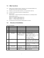
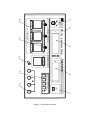
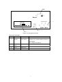
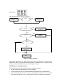
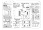
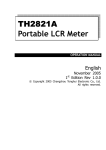
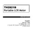
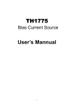
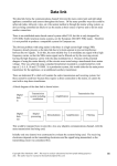
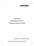
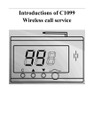
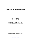
OPERATION MANUAL
TH2773A
Inductance Meter
Content
Chapter 1 General Introduction.........................................................................................................3
1.1
Product Introduction..............................................................................................................3
1.2
Specifications ........................................................................................................................3
1.3
Main functions ......................................................................................................................4
1.4
Structure & Installation .........................................................................................................4
Chapter 2 Operation Instruction........................................................................................................7
2.1 Notice..........................................................................................................................................7
2.2 Operation.....................................................................................................................................7
2.2.1 Power ...............................................................................................................................7
2.2.2 Connecting the DUT ........................................................................................................7
2.2.3 Display .............................................................................................................................7
2.2.4 Sorting function................................................................................................................8
2.2.5 Short correction function..................................................................................................9
2.2.6 Error ...............................................................................................................................10
Chapter 3 Maintenance & Repair....................................................................................................11
3.1 Maintenance ..............................................................................................................................11
3.1.1. Notice ............................................................................................................................ 11
3.1.2 Performance checking.................................................................................................... 11
3.1.3 Troubleshooting ............................................................................................................. 11
3.1.4 Signal checking ..............................................................................................................12
3.1.5 Standard .........................................................................................................................12
Chapter 4 Product package & Warranty..........................................................................................13
4.1 Product package ........................................................................................................................13
4.2 Warranty....................................................................................................................................13
2
Chapter 1 General Introduction
1.1
Product Introduction
Applying the most advanced measurement principle, TH2773A is a simple and intelligent
inductance meter with predominant function design, economic price, and fast
measurement speed (8 times/sec). It can measure inductance of different ranges under
different frequencies. It is a good choice for inductor incoming inspection and fast sorting
on product line.The instrument’s outstanding function is its sorting function, which has
simply-operated parameter setting, direct result indication, and beeper function, which can
easily tell the result.
1.2
Specifications
1.2.1
Measurement parameter
L: inductance
Q: quality factor
1.2.2
Test frequency:
1kHz±0.02%
100Hz±0.02%
1.2.3
Basic measurement accuracy:
L: ±[1uH+0.3%(1+0.2mH/L+L/20H)](1+1/Q)
Q: ±0.2%
1.2.4
Measurement range:
L: 0.1uH~100H
Q: 0.1~999.9
1.2.5
Test level: 0.3Vrms (no load)
1.2.6
Measurement speed: approx. 8times/sec
1.2.7
Pre-set range (BCD switch):
Nominal inductance: 0.01uH~990H
Inductance error limit: -99.9~99.9%
Quality factor limit: 0~99.9
1.2.8
Temperature: 0°C~40°C
Humidity: ≤80%RH
1.2.9
Power voltage: 220V±10%
Frequency: 50Hz±5%
Power consumption: ≤30W
Dimensions and weight
Dimensions: 270×130×300
Weight: approx. 5Kg
3
1.3
Main functions
1.3.1
Display mode: two display windows. Inductance (L) (or percentage deviation ∆%) ,
and quality factor (Q) are synchronously displayed.
1.3.2
Frequency: 100 Hz (conversion switch on), 1 kHz (conversion switch off)
1.3.3
Correction: Perform short correction by operating this key.
1.3.4
Sorting function:
When Q and ∆% meet limit requirement, PASS indicator is on, and beeper alarms
(can be turned on or off);
When Q is not qualified, QNG indicator is on;
When ∆% ≥ high limit, OVER indicator is on;
When ∆% ≤ low limit, DOWN indicator is on.
1.3.5
The instrument has strong protective design against concussion.
1.4
Structure & Installation
Front panel description
No.
Name
Description
Function
1
Power
2
Trademark & Model
3
Display
4 1/2-digit display
L & △% are displayed
4
Display
4-digit display
Value of Q is displayed
5
Manufacturer
6
Key switch
to select correction
display L-Q or △%-Q;
to select frequency
L: inductance value;
△%: percentage deviation
When L and △% are off, BCD
switch reading is measured.
CLR: short correction
f: on: 100Hz off: 1KHz
7
BCD switch
8, 4, 2, 1 BCD code
respectively
corresponding
to
inductance limit, quality factor limit,
high limit and low limit of inductance
8
LED indicator
9
Test terminal
HD, HS, LD, LS signal
test terminals
HD: high driving HS: high sampling
LD: low driving LS: low sampling
10
Grounding terminal
connecting ground line
terminal
connecting the ground line of the
device under test
Press to ON, to turn on power
PASS,
OVER,
DOWN,
QNG
respectively on according to the
sorting result
4
1
R
2
TONGHUI
ELECTRONICS
INDICATION
3
x□
x □
x
Q:
□
QNG
T H 27 7 3 A Inductance Meter
L
SORTING
DOWN
x□
x □
x%
LO:- □
LIMITS SETUP
7
mH
H
∆%
Q
STANDARD VALUE
※(0.XX*10 n)µΗ
x □
x □
n
Lm: □
9
HD
5
4
△%
HS
L
!
LS
CLR
UNKNOWN
8
PASS
f
1kHz
100Hz
LD
7
5
POWER
ON
OVER
x□
x □
x%
HI: □
OFF
6
Figure 1-1 Front panel overview
1
Beeper
2
220V 50Hz
S/N: 98008
Changzhou Tonghui Electronic Co., Ltd.
3
4
Figure 1-2 Rear panel overview
Rear panel description
No.
Name
1
Beeper
2
Power
outlet
3
Fuse
4
Nameplate
Description
2-bit switch
Function
ON: When the inductor is qualified, PASS
indicator is on, beeper alarms (it doesn’t in
other states).
OFF: Beeper is turned off.
fuse of 1A
6
Chapter 2 Operation Instruction
2.1 Notice
2.1.1 After unpacking, check with product package list.
2.1.2 Before operating the instrument, please read the manual thoroughly, or operate the
instrument under professional personnel’s instruction.
2.1.3 Line and neutral line through which power inputs should be of the same model as
those on the instrument’s power plug.
2.1.4 Connect test fixtures or test cable with four test terminals (HD, HS, LS, LD) on front
panel. When test cable is used, HD & HS, LD & LS should have short connection. For the
device under test (DUT) with guard shield, shielding plate should be connected with
grounding terminal of the instrument.
2.1.5 The instrument should be operated in the prescriptive environment. The instrument,
especially test leads connecting with the DUT, should be kept away from strong magnetic
field, to avoid interference.
2.1.6 When the measurement completes or it’s necessary to open the cover of the
instrument, power switch should be pressed to OFF, and please disconnect the instrument
from the power source.
2.2 Operation
2.2.1 Power
Perform the following steps to turn on the instrument:
1. Connect the instrument with the power source;
2. Press power switch to ON;
3. Numbers display in windows. Otherwise, restart the instrument;
4. Warm up for 15 minutes to the state of heat balance.
2.2.2 Connecting the DUT
Connect the DUT, and choose suitable test fixtures or cable. When cable is used, HD &
HS, LD & LS should have short connection. And the DUT’s lead should be clean to keep
good connection with test terminals.
2.2.3 Display
2.2.3.1 Press key switch to select display mode to L (inductance) or △% (percentage
deviation).
L: The instrument doesn’t directly display obtained measurement value in window after the
DUT is inserted, but judge whether the best range is selected. Only when the best range is
selected, are the data sent to be displayed. The inductance is displayed in 4.5-digit, and
7
quality factor (Q) in 4-digit.
△%: The instrument selects range according to the set value on BCD, and the result is
output after each measurement. The measurement speed is fast up to 8 times/sec. So the
mode is applied to fast measure batches of devices. The output result is displayed in
3-digit percentage, and quality factor in 4-digit. And ∆%=[(Lx-L)/L]×100%, where L is
nominal value, and Lx is measurement value.
In △% mode, nominal inductance is set in the mode of L×10n uH. For example, when the
nominal inductance is 47 mH, 47mH=47×103 uH=0.47×10⁵ uH,
The set value should be transformed into two-digit decimal and one-digit power, as the
following figure shows:
2.2.3.2 If L and △% are synchronously off, the instrument is in the state of measuring
BCD switch reading. The set inductance nominal value (L), high limit value (L-), low limit
value (L-), and quality factor limit value (Q-) are displayed, then press L or △% mode key.
The instrument will automatically enter the measurement state after this measurement
completes.
2.2.4 Sorting function
2.2.4.1 At the time of producing inductor or incoming inspection, a large number of
inductors of the same model need measuring. And it needs to be known whether the
component’s parameter is in some particular range, instead of its detailed value. This is
sorting. What the instrument is asked to do is to get the result fast and simply. TH2773A
provides the functions of one-bin inductance sorting and quality factor qualification sorting.
In all the modes of inductance direct reading (L), percentage deviation (△%), and quality
factor (Q), sorting function is valid.
2.2.4.2 Percentage limit and quality factor limit setting
When setting bin limit, inductance qualified bin that data on BCD switch denote is in the
form of percentage, and the default high limit is positive, low limit negative.
For example, the inductance bin limit is set from -12.3% to 45.6%, shown as the following
figure:
And quality factor limit is set to 10.2, shown as the following figure:
8
quality factor
The sorting procedure is shown in figure 2-1:
QNG
NO
indicator on
Qx≥Q—
YES
QNG
indicator off
NO
∆%≤L
—
OVER
indicator on
YES
NO
∆%≥L—
DOWN
indicator on
YES
NO
Qx≥Q—
YES
PASS
indicator on
RET
Figure 2-1 Sorting procedure
After setting inductance and quality factor limit, insert the inductance, to observe the
indicators on panel to judge whether the inductance is qualified or not. If beeper on rear
panel is turned on, beeper alarms when PASS signal is output.
2.2.5 Short correction function
TH2773 has short correction function. Perform the following steps:
1. Set the instrument’s test terminals to the short state;
2. Press correction key (CLR), and short distributing parameter Lo is measured out;
3. After connecting with the DUT Lx, the actual inductance value can be calculated
according to the formula: Lx=Lx’ (measurement result)-Lo (distributing parameter).
9
2.2.6 Error
The instrument’s operating environment and power supply are listed in Chapter 1.2.
Because range of L’s basic accuracy 0.3% and Q’s basic accuracy 0.2% is limited, please
precisely evaluate the instrument’s error when measuring inductor of some inductance
according to Chapter 1.2.3. In different frequencies, ranges that meet basic accuracy are
as follows (Q is considered infinite in ideal state):
1KHz: 100 uH ~ 1 H
100Hz: 1 mH
~ 10 H
Error factor (1+1/Qx) is omitted, and value of Q is little, so effect of Q should be
considered. If according to the formula, L’s accuracy is calculated to be 0.8%, and Q is
100, actual accuracy should be 0.808%.
Figure 2-2 Curve of the error
10
Chapter 3 Maintenance & Repair
3.1 Maintenance
3.1.1. Notice
3.1.1.1 The instrument should be maintained by experienced professional personnel.
3.1.1.2 At the time of maintenance, nominal frequency, resistance components, and
adjustable potentiometer can’t be adjusted or changed.
3.1.1.3 If the instrument is damaged because of user’s blindfold maintenance or changing
parts, the user should afford the maintenance charge.
3.1.2 Performance checking
3.1.2.1 Press display conversion key, to correctly change functions.
3.1.2.2 The instrument has checked all the working circuits, and it’s not necessary to
re-debug, because frequency and resistance standards are stabile. The following
components are optional to generally check the instrument’s operation.
3.1.2.3 Data’s validity
It’s one of the commonly-used methods to check the instrument’s operation according to
displayed data’s flicking. And the following notices should be paid attention to:
a. Observe after warming up for 15 minutes;
b. The chosen inductor should be stable, and standard inductor is the best choice;
c. The last number is allowed to flick in the range of accuracy’s 1/3 (The inductor under
test should be stable).
3.1.3 Troubleshooting
3.1.3.1 Safety precaution
a. Power should be cut off when opening the cover of the instrument.
b. Before maintenance, the instrument’s working principle, framework figure, circuit
principle figure, and installation figure should be known well.
c. Digital signal level should be less than 0.5V or more than 3V, or quickly convert
impulse signal between the two states.
d. If some digital signal is not normal, current level of about +2V is usually produced on
signal line.
e. If any trouble happens to microcomputer part, please send to local service office or
our company soon.
3.1.3.2 Common trouble
a. If the instrument doesn’t work, it can be tried to turn on and off power several times. If
the instrument still can’t recover, R101 or C101 on A1 control PCB, or power of +5V, is
11
usually checked.
b. Inductance’s high voltage may damage V205-V208, which may cause mistake of
instrument’s reading, or data’s quick flicking. This is usually because R213 (3Ω 1W)
is open or resistance increases.
c. If the inductance’s reading is normal, but quality factor obviously increases, there are
probably two reasons:
1. The test terminals don’t connect well or the test fixtures aren’t clean;
2. Performance of N207 (CD4052) gets poor.
d. If measurement in one range goes well, but reading mistake happens in another range,
there must be some problems with N206 (BU4053).
e. Mistake happens in display panel: 1. If there is no display at all, please check link’s
connection; 2. If there is no display at one segment, please change LED.
3.1.4 Signal checking
If there’s still problem that can’t be solved according to 3.1.3.2, further check and analysis
are needed.
3.1.4.1 Power
Please first check power according to the following table:
Pin No.
Standard
Voltage
Function
X105-1
+5V
+5V±0.3V
to supply digital circuit
X105-3
DGND
0V
digital ground
X204-1
+5V
+5V±0.3V
to supply analog circuit
X205-1
AGND
0V
Analog ground
X205-2
-8V
-8V±0.4V
to supply analog circuit
X205-3
+8V
+8V±0.4V
to supply
analog circuit
Table 3-1 Power tip of PCB
3.1.5 Standard
Analog signal’s nominating, happening and A/D conversion & comparison have close
relationship with instrument’s standard. And TH2773A’s +5V standard consists of
regulator V223, dynatron V224, and peripheral circuit.
Observed through oscilloscope, pin e of V224 should be direct current signal of +5V, or
measured through digital multimeter, it should be direct current signal of precise +5V.
Note
Analog signal ground (AGND) and digital signal ground (DGND) are absolutely separate.
At the time of maintenance, don’t connect them, otherwise, unexpected mistake will
happen.
12
Chapter 4 Product package & Warranty
4.1 Product package
The product package should include the following item:
1. TH2773A inductance meter
1
2. TH26004-1 4 terminal Kelvin test leads
1
3. three-core power cord
1
4. fuse
2
5. operation manual
1
6. product qualified certificate
1
7. warranty card
1
8. package list
1
9. testing report
1
After receiving the instrument, user should unpack to check. If there’s any problem, please
contact Tonghui Electronic Co., Ltd. or sales office at once.
4.2 Warranty
This instrument has 18 months’ free warrant, and lifetime’s maintenance. Please show
warranty card at the time of maintenance.
During the period of free warrant, if the instrument is damaged because of use’s misuse or
wrong operation, user should afford the maintenance charge.
13