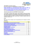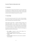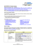
1
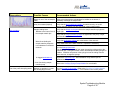
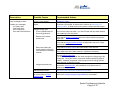
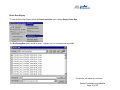
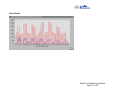
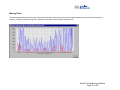
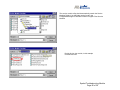
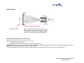
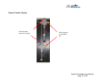
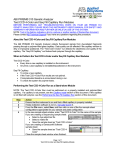
3700 Instrument-Spatial Troubleshooting Module
The purpose of this module is to guide the user through troubleshooting a spatial. The software instructions are for Data Collection
Software V2.0.
BEFORE PERFORMING ANY TROUBLESHOOTING WORK ON YOUR 3700 INSTRUMENT, PLEASE READ THE ABI PRISM® 3700
DNA ANALYZER USER'S MANUAL FOR SAFETY AND WARRANTY INFORMATION AND FURTHER DETAILS ON USE OF THE
SYSTEM.
Please contact technical support if you have any questions regarding the document.
The use of Service Tools is advised only under the recommendation of an Applied Biosystems’ representative.
Checking the array for broken capillaries
Before installing a new array it is recommended to check the array for broken capillaries, the loading end, the length of the array and the
detection end. Refer to the array diagram for specific areas. If the array is broken, please report the problem to technical support.
Preparing for a Spatial
Before starting a spatial it is important to ensure that the instrument is running properly and the reagents are fresh.
Follow the checklist below:
♦Perform system maintenance. Refer to the 3700 Instrument Maintenance Module.
♦Check for bubbles in the cuvette, if present run the cuvette flush module. Refer to the Checking CCD view module
♦Spatial reagents should be fresh. If reagent age is unknown or was stored improperly (recommended storage is 2°-8°C), order a new
spatial calibration standard, part number 4325775. The spatial buffer can be made by combining 100uL of 3700 10X buffer and 900uL
of fresh HiDi formamide.
♦Ensure that the correct run module is being used for the polymer and run type.
SpatSQ2_POP5DefaultModule for sequencing applications using POP5 polymer
SpatSQ2_POP6DefaultModule for sequencing applications using POP6 polymer
SpatGS2_POP6DefaultModule for fragment analysis applications using POP6 polymer
SpatSNP2_POP5DefaultModule for the SNPShot applications using POP5 polymer
Monitoring a spatial run
During a spatial run, it is possible to monitor the run through the array view page. This page provides a quick overview of a run and is
useful in identifying hardware related issues that can affect the spatial.
If a spatial run has failed the spatial information can only be viewed through the entire run display window in Data Collection Software
v2.0.
Spatial Troubleshooting Module
Page 1 of 30
Spatial Passes but quality is questionable. Another spatial will have to be performed after performing the recommended
actions.
Observations
Possible Causes
Recommended Actions
Left to Right Variation has a ratio
greater than 1:3.
Bubble in the cuvette
Run the Cuvette Flush module. Refer to the Checking for Bubbles Module
and the Checking for Leaks Module if the bubbles in the cuvette persist.
Cuvette temperature needs
optimization
Optimize cuvette temperature in +/- 3°C increments. The temperature can
range from 35° to 50°C.
Refer to page 4-16 of the ABI Prism® 3700 DNA Analyzer User Guide for
instructions on optimizing the temperature.
Capillary array alignment
problem
Verify that the array loading-end header is seated correctly, not under
tension, and the capillary tips are positioned in their injection wells.
click to enlarge
Set of four pattern
Verify that the thumbscrews on the detection end base are not too tight,
finger-tight is sufficient, and are screwed on with equal tightness.
Capillary array damage
Check the loading end of the array for damage and if necessary, remove the
array and check the detection end for broken capillaries. If observed, install
a new array.
Improperly preparing the spatial
standard.
Prepare the 200uL of each color standard in a single tube, vortex or pipettemix, and then pipette 100uL of standard into 2 tubes for running. This
ensures that each tube is identical. Spin down samples before placing on
the instrument.
Sample loading issue
Bubbles in the sample wells
click to enlarge
Or
Bubbles in the sample
transfer lines
Spin down samples before placing on the instrument. Inspect the tubes for
bubbles in the bottom of the well.
Verify that the fittings on the ports above the sample transfer syringes are
finger tight.
Spatial Troubleshooting Module
Page 2 of 30
Observations
Possible Causes
Recommended Actions
Pattern of highs and lows
Verify that the sample transfer syringes are tightened to the pump. Finger
tight should be sufficient.
(in this case, eight high signals and
eight low signals)
Verify that the fluid line sinkers are at the bottom of the reservoir.
Verify water levels in the water reservoir. Replenish if necessary.
Run the Change tips wizard.
This will prime the syringes and flush water through the tubing going to the
loading tips. During the wizard, monitor both sample transfer syringes for
bubbles. If bubbles are present in the syringe but not the tubing from the
water reservoir, change the syringe.
click to enlarge
Broad peaks
Clogged autoloader tips
Replace the autoloader tips. Refer to the change tips wizard for instructions.
A non-functioning sample
transfer pump
Refer to the Verifying Syringe Pumps Module for more details.
No Sheath Flow
Check the sheath flow syringe for leakage, replace syringe if necessary.
Check for leakage around the sheath flow syringe fittings. Clean the area
with a lint free tissue moistened with DI water and tighten the fittings until
finger tight. Refer to the Checking for Leaks Module.
The syringe pump may not be moving. Refer to the Verifying Syringe Pump
Module to troubleshoot.
click to enlarge
Missing
peaks
Run the Cuvette Flush module. Refer to the Checking for Bubbles Module
and the Checking for Leaks Module if the bubbles in the cuvette persist.
Improperly mixed red standard
Prepare the 200uL of each color standard in a single tube, vortex or pipettemix, and then pipette 100uL of standard into 2 tubes for running. This
ensures that each tube is identical. Spin down samples before placing on
the instrument.
Spatial Troubleshooting Module
Page 3 of 30
Observations
click to enlarge
Possible Causes
Recommended Actions
Bubble in one of the red sample
tubes
Inspect the tubes with the red standard for bubbles in the bottom, if
necessary centrifuge the sample tube.
Array is not seated properly
Verify that the array loading-end header is seated correctly, not under
tension, and the capillary tips are positioned in their injection wells.
Sample loading issue
Bubbles in the lines of one of
the sample transfer tips.
Verify that the fittings on the ports above the sample transfer syringes are
finger tight.
Verify that the sample transfer syringes are tightened to the pump. Finger
tight should be sufficient.
Water lines feeding the
sample transfer pumps are
not underwater in the water
reservoir
A clogged autoloader tip
A non-functioning sample
transfer pump
Part of the profile has spiky peaks
Bubbles or particles in cuvette
are causing bright events.
Verify that the fluid line sinkers are at the bottom of the reservoir.
Verify water levels in the water reservoir. Replenish if necessary.
Run the Change tips wizard.
This will prime the syringes and flush water through the tubing going to the
autoloader tips. During the wizard, monitor both sample transfer syringes for
bubbles. If bubbles are present in the syringe but not the tubing from the
water reservoir, change the syringe.
Replace the autoloader tips. After installation verify that the tips are
tightened until finger tight.
Refer to the Verifying Syringe Pumps Module for more details.
Run the Cuvette Flush module. Refer to the Checking for Bubbles Module
and the Checking for Leaks Module if the bubbles in the cuvette persist.
Spatial Troubleshooting Module
Page 4 of 30
The next set of observations is for spatials that generate the following message:
The message can be accompanied by the following errors:
Red Profile Error
Blue Profile Error
Blue and Red Profile Error
End Caps Blocked
No Alignment Found
Non Unique Alignment
Cap Spacing Out of Range
Too Many Caps
No Caps Found
In these cases the spatial fails and does not display a profile in Data Collection V2.0 software. It will be necessary to use the “Entire
Run Display” feature to assist with troubleshooting. Another spatial will have to be performed after performing the recommended
actions.
Spatial Troubleshooting Module
Page 5 of 30
Observations
Possible Causes
Entire run display is blank
Loss in communication
Possible error messages:
No Caps Found
Red Profile Error
Blue Profile Error
Blue and Red Profile Error
Optics
Recommended Actions
Restart the system
Check the CCD window, for raman lines. Refer to the Checking CCD
Window module. If raman lines are not present, contact technical support.
Sample loading issue
The four spatial tubes are
incorrectly positioned
Place the four tubes into wells 1–4 of the left 8-bar and spin down samples
before placing on the instrument.
Bubbles in the sample
transfer lines
Verify that the fittings on the ports above the sample transfer syringes are
finger tight.
Verify that the sample transfer syringes are tightened to the pump. Finger
tight should be sufficient.
Water lines feeding the
sample transfer pumps are
not underwater in the water
reservoir
Verify that the fluid line sinkers are at the bottom of the reservoir.
Verify water levels in the water reservoir. Replenish if necessary.
Run the Change tips wizard.
This will prime the syringes and flush water through the tubing going to the
loading tips. During the wizard, monitor both sample transfer syringes for
bubbles. If bubbles are present in the syringe but not the tubing from the
water reservoir, change the syringe.
Clogged autoloader tips
Replace the autoloader tips. After installation verify that the tips are
tightened until finger tight.
Electrophoresis Issues
Refer to the Electrophoresis Troubleshooting Module
A non-functioning sample
transfer pump
Refer to the Verifying Syringe Pumps Module for more details.
Spatial Troubleshooting Module
Page 6 of 30
Observations
Possible Causes
Recommended Actions
Entire run display has only one
color, blue or red.
Improperly prepared spatial
standard.
Prepare the 200uL of each color standard in a single tube, vortex or pipettemix, and then pipette 100uL of standard into 2 tubes for running. This
ensures that each tube is identical. Spin down samples before placing on
the instrument.
Sample loading issue
Bubbles in the sample
transfer lines
Verify that the fittings on the ports above the sample transfer syringes are
finger tight.
Possible error messages:
Red Profile Error
Blue Profile Error
Blue and Red Profile Error
End Caps Blocked
No Alignment Found
Water lines feeding the
sample transfer pumps are
not underwater in the water
reservoir
Clogged autoloader tips
Verify that the sample transfer syringes are tightened to the pump. Finger
tight should be sufficient.
Verify that the fluid line sinkers are at the bottom of the reservoir.
Verify water levels in the water reservoir. Replenish if necessary.
Run the Change tips wizard.
This will prime the syringes and flush water through the tubing going to the
autoloader tips. During the wizard, monitor both sample transfer syringes for
bubbles. If bubbles are present in the syringe but not the tubing from the
water reservoir, change the syringe.
Replace the autoloader tips. After installation verify that the tips are
tightened until finger tight.
Random capillaries do not have
signal present.
Possible error messages:
End Caps Blocked
No Alignment Found
A non-functioning sample
transfer pump
Refer to the Verifying Syringe Pump Module.
Bubbles in the cuvette
prevented fluorescence from
some capillaries from being
detected
Verify that there is enough polymer in the polymer bottle for the run.
Run the CuvetteFlush.mod service module. Refer to the Checking the CCD
Window Module to determine if bubbles are still in the cuvette.
Refer to the Checking for Bubbles Module if bubbles remain in system.
Spatial Troubleshooting Module
Page 7 of 30
Observations
Possible Causes
Non Unique Alignment Cap
Spacing Out of Range
Recommended Actions
Replace the inline filter.
Array is not seated properly
Verify that the array loading-end header is seated correctly, not under
tension, and the capillary tips are positioned in their injection wells.
Broken capillaries on the array
Check the array for broken capillaries at the loading end, the length of the
array and the detection end of the array. If breakage is observed, replace
the array.
Capillary Array has dried out and Run the Regenerate part of the Change Array wizard to clear the blockage, it
may not work depending on the severity of the block.
capillaries are blocked with
polymer.
Replace with a new capillary array.
Bright events are present in the
cuvette which are detected as false
peaks
Possible error messages:
Non Unique Alignment
Cap Spacing Out of Range
Too Many Caps
A few peaks have greater intensity
than the others
Leaking sheath flow syringe
Inspect the sheath flow syringe for leakage at ports and within the barrel.
Replace sheath-flow syringe if leakage is found.
Leaking inline filter
Inspect the tubing around the inline filter for leakage, indicated by dried
polymer. If leaking is observed, replace the inline filter and run the Cuvette
Flush module. Refer to the Checking for Bubbles Module and the Checking
for Leaks Module if the bubbles in the cuvette persist.
Particles in the cuvette
Inspect the tubing around the inline filter for leakage, indicated by dried
polymer. If leaking is observed, replace the inline filter.
Run the CuvetteFlush.mod service module.
Capillary array may be
misaligned
Verify that the thumbscrews on the detection end base are not too tight and
are screwed on with equal tightness.
Bubbles in the cuvette.
Run the Cuvette Flush module. Refer to the Checking for Bubbles Module
and the Checking for Leaks Module if the bubbles in the cuvette persist.
Spatial Troubleshooting Module
Page 8 of 30
Observations
Possible Causes
Recommended Actions
Presence of reflective particles
in the cuvette
Inspect the tubing around the inline filter for leakage, indicated by dried
polymer. If leaking is observed, replace the inline filter.
Run the CuvetteFlush.mod service module.
Capillaries on one side of the array
have no fluorescence
Bubbles in the cuvette
Run the Cuvette Flush module. Refer to the Checking for Bubbles Module
and the Checking for Leaks Module if the bubbles in the cuvette persist.
or
Cuvette temperature needs
optimization
Optimize cuvette temperature in +/- 3°C increments. The temperature can
range from 35° to 50°C.
Refer to page 4-16 of the ABI Prism® 3700 DNA Analyzer User Guide for
instructions on optimizing the temperature.
Array is not seated properly
Verify that the array loading-end header is seated correctly, not under
tension, and the capillary tips are positioned in their injection wells.
Sample loading issue
Bubbles in the sample
transfer lines
Verify that the fittings on the ports above the sample transfer syringes are
finger tight.
A large group of capillaries have a
very low signal
Possible error messages:
Red Profile Error
Blue Profile Error
Blue and Red Profile Error
End Caps Blocked
No Alignment Found
Verify that the sample transfer syringes are tightened to the pump. Finger
tight should be sufficient.
Water lines feeding the
sample transfer pumps are
not underwater in the water
reservoir
Verify that the fluid line sinkers are at the bottom of the reservoir.
Verify water levels in the water reservoir. Replenish if necessary.
Run the Change tips wizard.
This will prime the syringes and flush water through the tubing going to the
autoloader tips. During the wizard, monitor both sample transfer syringes for
bubbles. If bubbles are present in the syringe but not the tubing from the
water reservoir, change the syringe.
Clogged autoloader tips
Replace the autoloader tips. After installation verify that the tips are
tightened until finger tight.
Spatial Troubleshooting Module
Page 9 of 30
Observations
Wide peaks
Possible Causes
Recommended Actions
A non-functioning sample
transfer pump
Refer to the Verifying Syringe Pump Module.
No sheath flow (the most
common cause)
Check the sheath flow syringe for leakage, replace syringe if necessary.
Possible software messages:
No Alignment Found
Non Unique Alignment
Cap Spacing Out of Range
Check for leakage around the sheath flow syringe fittingsT. Clean the area
with a lint free tissue moistened with DI water and tighten the fittings until
finger tight. Refer to the Checking for Leaks Module.
The syringe pump may not be moving. Refer to the Verifying Syringe Pump
Module to troubleshoot.
If problem persists, please contact technical support.
Contacting Technical Support
By phone:
By email:
1-800-831-6844, option 5
[email protected]
Spatial Troubleshooting Module
Page 10 of 30
The Array View
The array view is an option in the Data Collection software, which allows monitoring of the data during or after a run. It is provides a
quick overview of a run and is useful in identifying hardware related issues that can affect the samples. See the Array View Colors
Troubleshooting Module for more information.
How is the array view accessed in Data Collection V2.0?
During a run
1) Select the Run Status tab > select Array View.
Caution Always exit the Array View when you are finished viewing. Do not leave the window open for extended periods during a
run as this may cause unrecoverable screen update problems.
Spatial Troubleshooting Module
Page 11 of 30
Entire Run Display
To view the Entire Run Display select the Data Acquisition menu >select Display Entire Run.
The RunDisplayData folder should be open. Highlight your run of interest and select OK.
This window will display the entire run.
Spatial Troubleshooting Module
Page 12 of 30
Two different oligomers, one labeled
with dROX (Red) and the other labeled
with dR110 (Blue), are loaded to all
104 capillaries in a special pattern.
– Caps 1 - 4: receive red dye
– Caps 5 - 100: receive blue and red,
alternating by capillary
– Caps 101 - 104: receive blue dye
Spatial Troubleshooting Module
Page 13 of 30
Left to Right Variation
Optimized spatial. Note the uniformity across the array.
Although a peak is missing, the software will
extrapolate the position of this capillary.
Spatial Troubleshooting Module
Page 14 of 30
Severe Left to Right Signal Variation
Optimize the cuvette temperature in +/- 3°C increments. Temperature gradients in the cuvette cause deviation of the
laser beam. If a bubble is not present in the cuvette, try modifying the method by changing the cuvette temperature in +/- 3°C
increments. From the default temperature of 40°C, initially try 37°C and 43°C cuvette temperature when running the Spatial Calibration.
Running at both temperatures will help to determine if it is necessary to increase or decrease the temperature incrementally. Continue
to change the temperature incrementally to get an optimal spatial. The temperature range should be from 35°C to 50°C, do not go
lower than 34°C as the instrument may error. A high ambient temperature can prevent the instrument from reaching temperatures
below 34°C. Once the temperature is optimized, run the spatial and all subsequent runs using this array with the optimized
temperature. Temperature gradient problems may show other possible profiles such as higher signal on the left than on the right, or a
“smile” pattern.
Spatial Troubleshooting Module
Page 15 of 30
Set of Four
Set of Eight
Spatial Troubleshooting Module
Page 16 of 30
Broad Peaks
Spatial Troubleshooting Module
Page 17 of 30
Missing Peaks
The spatial passed despite missing many red plumes because the spacing was correct and the spatial algorithm could guess the missing plume
positions. Although it passed, this profile is indicative of a problem, and the spatial should be rerun.
Spatial Troubleshooting Module
Page 18 of 30
Running service modules within Data Collection V2.0
Step 1: Go to the Instrument menu > Select
Utilities > Select Run Service Module >
Step 2:Click the Select Module button
Spatial Troubleshooting Module
Page 19 of 30
The service module utility should automatically search the Service
Modules Folder, if not the folder can be found in the
D://AppliedBio/Support Files/Data Collection Support Files/ Service
Modules
Double click on the module, in this example
CuvetteFlush.mod.
Spatial Troubleshooting Module
Page 20 of 30
After selecting run method, the steps of the service module will be listed.
The module selected should be listed.
Select Run Method.
Spatial Troubleshooting Module
Page 21 of 30
When this window appears the module has completed, if there is an error during the module,
please contact technical support.
Spatial Troubleshooting Module
Page 22 of 30
ARRAY
Loading End of Array
The loading-end header is the unit that holds the capillaries at the sample-loading end of the capillary array and aligns them with the injection wells of
the loading bar.
The diagram below shows how the loading-end header is held in the loading block.
Spatial Troubleshooting Module
Page 23 of 30
Array Diagram
Loading end of array
Broken capillaries along the length of the array can
be problematic if the array is not changed. Polymer
will still flow through the capillary causing buildup of
polymer in the area and affecting other capillaries.
Exposing the Detection end of the array
Step 1: While holding the detection-end base in front of you:
a. Pull the tip-cover clips laterally.
b. Carefully slide the tip cover downwards to expose the tips and O-ring.
IMPORTANT With the cover retracted, the fragile ends of the capillaries are exposed. Any trauma to the tips, such as pressure from fingers during
handling, will cause the tips to break and make the array unusable.
The tips should appear uniform in height. Before installing the array on the instrument, return the tip-cover to its original position.
Spatial Troubleshooting Module
Page 24 of 30
The capillary tips. Do
not touch the capillary
tips as they are delicate
and may break.
Thumbscrews
Thumbscrews
These should be tightened until finger tight
Spatial Troubleshooting Module
Page 25 of 30
Sheath Flow syringe and pump
The red arrows identify areas of possible leaks.
Port 8: From polymer bottle to syringe
Port 9: From syringe to cuvette
Minimal leakage. Syringe may still be used but
should be cleaned regulary and monitored. If
problems persists, change syringe.
Severe leakage. Replace syringe.
Dried polymer appears as a white residue inside of the barrel.
If present the dried polymer acts as an abrasive against the
plunger and can damage the seal to the glass barrel. If the
seal is damaged, bubbles can be introduced at this stage.
Replace the syringe using the Change syringe wizard.
Spatial Troubleshooting Module
Page 26 of 30
Sample Transfer Syringe
Port from water
reservoir to syringe
Port for syringe
to autoloader
tips
Spatial Troubleshooting Module
Page 27 of 30
Running the wizard
Step 1: Select Instrument
Step 2: Select Wizards
Step 3: Select the appropriate wizard.
Autoloader Tips
Autoloader tips
Tips should be wiped in a downward direction to prevent
clogging during cleaning.
Spatial Troubleshooting Module
Page 28 of 30
Fluid Line Sinkers
Fluid line sinkers
Inline Filter
Dried polymer will
appear in these areas.
Inline filter
Spatial Troubleshooting Module
Page 29 of 30
Restarting the 3700 DNA Analyzer
IMPORTANT To prevent firmware and software memory problems, we recommend that you restart the instrument and the software once a week.
To shut down and restart the instrument:
Step 1: The instrument should not be running or extracting data.
Step 2: Close the 3700 Data Collection software by selecting Shutdown from the File menu.
Note You cannot use the Close button to exit the software.
Step 3: Close the OrbixWeb Daemon software by right-clicking on its button in the taskbar and selecting Close from the pop-up menu. If you get a
run-time message, click OK to close the message.
IMPORTANT Do not shut down the OrbixWeb™ Daemon until after you have shut down the Data Collection program.
Step 4: Restart the computer. After logging in, OrbixWeb™ Daemon should have automatically launched. Do not start Data Collection at this time.
Step 5:
a. Turn off the instrument using the On/Off button.
b. Wait 30 seconds.
c. Turn on the instrument.
Step 6: When the green status light is steady, wait 1 minute.
Step 7: Restart the 3700 Data Collection software.
Spatial Troubleshooting Module
Page 30 of 30