1
2
Contents
1. Introduction......................................................................... 4
2. Features ................................................................................ 6
3. Technical Specification ...................................................... 7
4. Measure of Appearance .................................................... 9
5. Front Panel ........................................................................ 10
6. Rear Panel ......................................................................... 14
7. How to Install .................................................................... 15
8. Calibration Mode ............................................................. 16
9. Set Mode ............................................................................ 24
10. Test Mode......................................................................... 43
11. Weighing Mode............................................................... 47
12. Serial Interface(COM1, COM2) ................................ 63
13. Options ............................................................................. 67
3
1. Introduction
Thank you for purchasing the CAS CI-6000A weighing indicator.
We have designed this equipment with many advanced features, high quality construction, and userfriendly menu driven programming.
CAS indicator is shaped firmly and delicately designed to coincide with the special requirements of
several industrial fields and includes many functions and various external interfaces. Also, it contains
help display functions to be used easily.
Before using CI-6000A, It is recommended to read this manual carefully and to apply
the function application fully.
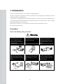
Precautions
Observe the following safety precautions :
Warning
When any damage or defect
occurs, contact your CAS
authorized dealer immediately
for proper repair.
Do not pull the plug by its cord
when unplugging. Damaged
cord could cause electric shock
or fire.
Insert plug firmly to wall outlet to Scale must be grounded to
prevent electric shock.
minimize electricity static. This
will minimize defect or electric
shock.
To prevent from fire occurring,
Do not place or use the scale
near flammable or corrosive
gas.
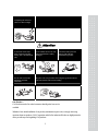
4
To reduce electric shock or
incorrect reading, Do not spill
water on the scale or place it in
humid condition.
Avoid placing the scale near
heather or in direct sunlight.
Attention
For consistent and accurate
reading, maintain periodical
check by your CAS authorized
dealer.
Avoid sudden shock to the scale.
Internal mechanism could by
damaged.
Place the scale on firm and
temperature consistent
environment.
Keep the scale away from the electromagnetic generation devices.
This may interfere with accurate reading.
Attach the rubber pad to the
bottom of the indicator.
Elimination is possible.
Our Dealers :
CAS feels that each of its valued customers should get the best service
available.
Whether it’s the initial installation of our product, maintenance/repair work, or simply answering
questions about our products, CAS Corporation and all of its Authorized Dealers are highly trained to
assist you with any need regarding CAS products.
5
2. Features
1) Features
■ High speed, High accuracy
■ The adoption of high speed micro processor
■ A/D conversion speed : Maximum 200 times/sec
■ Appropriate for weighing and measurement system
■ Easy operation and various options
■ Simple and prompt Full Digital Calibration
(SPACTM : Single pass automatic span calibration)
■ RFI/EMI screened
■ WATCHDOG circuitry (System restoration)
■ WEIGHT BACK-UP
(Weight memory at sudden power failure)
2) Main Functions
■ Save date, time and calculated data at sudden power failure
■ Various specification of weight conversion speed
(Digital filter function)
■ Various printer connection (RS-232C Serial printer)
■ Tare weight setting with keys
■ Storage of measured times
■ Read / Write Set-point values(7) through the PC
- each to set-point code(0~49)
■ Read / Write Set Mode values(23) through the PC
■ External 6 relays for input / 8 relays for output
■ Users can set the max. weight and a division freely
■ Control various external equipment by inner external input/output
■ Print date and time by built-in clock
■ Self hardware test.
6
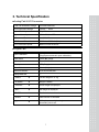
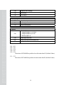
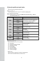
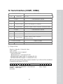
3. Technical Specification
■ Analog Part & A/D Conversion
Load Cell Excitation Voltage
8 x 350Ω load cells
Zero Adjustment Range
0.05mV ∼ 20mV
Input Sensitivity
0.6μV/D
System Linearity
Within 0.01% of FS.
A/D Internal Resolution
1 / 1,000,000
A/D External Resolution
5,000 dd, 10,000 dd (Max)
A/D Conversion Speed
Maximum 200 times/sec
■ Digital Part
Span Calibration
Full Digital Calibration : SPAC™
(Single pass automatic span calibration)
Input Noise
Under ±0.3μVpp
Input Impedance
Over 10M Ω
Display
VFD (7 digit)
Size of letter
13mm (Height)
Minimum division
x1, x2, x5, x10, x20, x50
Display below zero
“-”
"ZERO"
▼
Current weight of “0” kg
"STABLE"
▼
Weight is stable
"GROSS"
▼
Gross weight is displayed
"NET"
▼
Net weight is displayed
"TARE"
▼
Tare function is activated
"HOLD"
▼
Hold function is activated
"*"
▼
" * " key is pressed (print key)
Automatic print is set.
7
■General Specification
AC 100 ~ 240V (50/60 Hz) Input
Power
Product Size
DC +3.3V
Digital Logic
DC +24V
External I/O
DC +5V
Analog, Load Cell
AC 3.6V
VFD
192(W) x 189(D) x 96 (H)
Temperature Range
-30℃ ~ +60℃
Product Weight
Approx. 2.4 kg
8
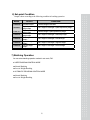
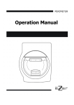
4. Measure of Appearance
9
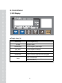
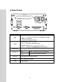
5. Front Panel
1) VFD Display
■ Display Lamp(▼)
ZERO lamp
ST lamp
GROSS lamp
NET lamp
TARE lamp
Current weight is 0 kg
Weight is stable
Current weight is gross weight
Current weight is net weight
Tare weight is saved
HOLD lamp
Lamp is on when HOLD function is activated
* lamp
Lamp is on only when “*” key is pressed. And F23 is
set to “1” in the set mode
Automatic print should be set to “1” in set mode
(F41 = 1 or 2, F42 = 1)
10
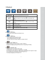
2) Keyboard
You can use these keys as numeric keys
Change the set value
key increases set value and
key decreases set
value
Change the position of cursor
key moves one digit to right,
key moves one digit
to left
Use 1
Enter tare weight
Use 2
Enter set-point value
Use 3
Enter the set value in TEST, CAL, SET mode
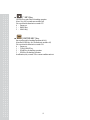
■
[ ZERO ]Key
Used to remove small variations in the indicator’s zero
■
[ TARE ] Key
Used to weigh an item by using the container
Current weight is memorized as tare weight
If you press TARE key in unload condition, tare setting is released
■
[ KEY TARE ] Key
When you already know the tare weight, press KEY TARE Key
and enter tare weight by pressing arrow keys and save it by pressing ENTER key
■
[ G/N KEY ] Key
Toggles the display between gross and net weight
G. weight lamp on - gross weight / N. weight lamp on - net weight
If tare weight is saved, tare plus item's weight is gross weight and only item's weight is net weight
You can prohibit using of keyboard by pressing G/N key for 5 sec.
To use keyboard again, press G/N key for 5 sec
11
■
[ * KEY ]Key
Used to set set-point value for batching operation.
(Press * key for 3 seconds more and take off)
You can select this function in set mode F23
0 : Do not use.
1 : PRINT Key.
2 : HOLD Key
■
[ ENTER KEY ] Key
Set set-point code for batching operation.(00~49)
(Press the ENTER key for 3 seconds more and take off)
You can select this function in set mode F24.
0 : Do not use.
1 : TOTAL PRINT key.
2 : START key for batching operation.
3 : STOP key for batching operation.
In calibration, test, set mode : Save current condition and exit
12
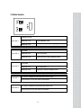
3) Slide Switch
Calibration mode
SW1 DIP 1
Switch DIP 1 on
Go to calibration mode
Switch DIP 1 off
After calibration, it returns to weighing mode
Set mode
SW1 DIP 2
Switch DIP 2 on
Go to set mode.
Switch DIP 2 off
After set mode, it returns weighing mode.
Test mode
SW1 DIP 3
SW2 DIP 1
Switch DIP 3 on
Go to test mode.
Switch DIP 3 off
After test, it returns to weighing mode
It is used in calibration mode when zero value is high
If you set DIP 1 to on, zero value is decreased.
SW2 DIP 2
It is used in calibration mode when zero value is low
If you set DIP 2 to on, zero value is increased
13
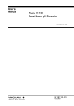
6. Rear Panel
OPTION
AC
LOADCELL
T250mA
L250V
COM1
COM2
CONTROL I/O
RS-232 cable( 2 : TxD, 3 : RxD, 5,7 : Gnd )
COM1
- F33 = 1 ~ 4 function is enable (both of Set-point and Setmode) to read and write
- Computer, sub-display and printer
RS-232 cable( 2 : TxD, 5,7 : Gnd)
COM2
- F36 = 1 ~ 2 function is enable to read only
RS-485/422 cable( 6 : Rx+, 7 : Rx-, 8 : Tx+, 9 : Tx- )
- F36 = 1 ~ 4 function is enable(Set-point) to read and write
LOAD CELL
CONTROL I/O
OPTION
AC
FUSE
Port for connecting. 4-wires, 6-wires load cell
External
input
External
output
ZERO, TARE,START,STOP,*,ENTER key
External output for batching operation
When option is used, please connect
100 ~ 240VAC are available
T250mA L250V
14
7. How To Install
1) Load cell connection
Connect load cell connector to load cell port which is in the backside CI-6000A
* Connecting method
PIN
1 (EXC+)
2 (SEN+)
3 (EXC-)
4 (SEN-)
5 (SIG+)
6 (SIG-)
7 (SHIELD)
Note 1. In case of 4 wires L/C connect EX+ with SEN+, and connect EX- with SEN-.
Note 2. Wire color can be different depending on the load cell’s manufacturer or its model
2) Power
Adjusted to 220V 50/60Hz at factory.
(If you want to use 110V, adjust 110V/220V jump wire which is located
in the inner part of CI-6000A)
15
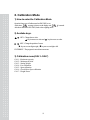
8. Calibration Mode
1) How to enter the Calibration Mode.
Open the front cover of indicator and set SW1 DIP1 to on.
At this time,
message is shown on the display and
After done and off the SW1 DIP1, back to the weighing mode.
is started.
2) Availabe keys.
KEY : Change the set value.
key increases set value and
key decreases set value.
KEY : Change the position of cursor.
key moves one digit to right, key moves one digit to left.
ENTER KEY : The program is moved into next menu.
3) Calibration menu(CAL1~CAL7)
CAL 1 : Maximum capacity
CAL 2 : Minimum division
CAL 3 : Setting Weight
CAL 4 : Zero calibration
CAL 5 : Span calibration
CAL 6 : Check Micro Span calibration
CAL 7 : Weight Factor
16
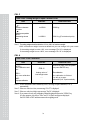
CAL 1
FUNCTION : Maximum Capacity Set (Range : 1 ~ 99,999)
KEY
:
Increase or decrease
of number
:
Shift of cursor position
ENTER :
Save and go to next
menu
DISPLAY
DESCRIPTION
C = 05000
5000 kg
C = 0500.0
500.0 kg(First decimal point)
C = 050.00
50.00 kg (Second decimal point)
Note 1. The maximum capacity means the maximum weight of the indicator.
Note 2. The max. weight is changed depending on the decimal point.
CAL 2
FUNCTION : Minimum Division Set (Range : 0.001 ~ 50)
KEY
:
Increase or decrease
of number
ENTER :
Save and go to next
menu
DISPLAY
d=1
DESCRIPTION
1 kg
d = 0.2
0.2 kg (First decimal point)
d = 0.05
0.05 kg (Second decimal point)
d = 0.001
0.001 kg (Third decimal point)
Note 1. The minimum division means the value of one division.
Note 2. The value of one division is changed depending on the decimal point.
Note 3. External resolution is obtained by dividing the maximum capacity into the min. division.
Set the resolution to be within 1/10,000.
If it is over 1/10,000, error message "Err 20" is displayed
17
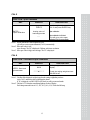
CAL 3
FUNCTION : Setting Weight In Span CALIBRATION
KEY
:
Increase or decrease
of number
:
Shift of cursor position
ENTER :
Save and go to next
menu
DISPLAY
DESCRIPTION
L=05000
5000 kg
L=0500.0
500.0 kg (First decimal point)
Note 1. The setting weight should be within the 10 % to 100 % of maximum weight
100% of maximum weight is set as a default but you can change it for your needs
If the setting weight is under 10%, error message "Err 22" is displayed
If the setting weight is over 100%, error message "Err 23" is displayed
CAL 4
FUNCTION : Zero Calibration
KEY
ENTER :
Zero calibration and
next
ZERO :
Only zero calibration
TARE :
Only span calibration
DISPLAY
CAL 4
Analog value of
load weight state
---
DESCRIPTION
Remove an item from the platter
and press ENTER key.
Zero calibration.
Zero calibration is finished.
You will go to span
calibration(CAL 5)automatically.
Note 1. If Zero calibration is done without any error, You will go to span calibration (CAL 5)
automatically.
Note 2. If the zero value is too low, error message "Err 27" is displayed.
Note 3. If the zero value is too high, error message "Err 26" is displayed.
Note 4. If you want to do only zero calibration, unload the platter and press the "ZERO" key.
In a few moment, you will see "ZEro" and "CAL End" messages are displayed.
Set SW1 DIP1 to OFF and then return to the weighing mode.
18
CAL 5
FUNCTION : Span Calibration
KEY
DISPLAY
CAL 5
ENTER :
Span calibration
Analog value of
load weight state
DESCRIPTION
Load the weight which was set in
CAL 3 and press ENTER key.
Span calibration.
Span calibration is finished.
You will go to micro span
calibration(CAL 6) automatically.
---
Note 1. If span calibration is done without any error,
you will go to micro span calibration (CAL 6) automatically.
Note 2. If the span value is low,
error message "Err 24" is displayed. Calibrate with lower resolution.
Note 3. If the span value is high, error message "Err 25" is displayed.
CAL 6
FUNCTION : Check Micro Span Calibration
KEY
DISPLAY
500.0
ENTER : Save and
go to next menu
DESCRIPTION
Setting weight is shown on the
display.
▽▽▽▼▽▽▽
Check the setting weight and set
SW1 DIP1 to off.
Note 1. Confirm if the displayed weight is equal to the setting weight that you have
set in CAL 3 and remove the weight from the platter.
If "0" is displayed, set SW1 DIP1 to OFF then you will go to normal mode.
Note 2. The bias is "0" when the central lamp lights up as above display.
Each lamp means the bias of -0.3, -0.2, -0.1, 0, 0.1, 0.2, 0.3 from the left lamp
19
CAL 7
FUNCTION : Weight Constant Calibration
KEY
:
Enter password.
ENTER : Exit
DISPLAY
FACtor
DESCRIPTION
Enter password.
Note 1. Users do not have to use this menu, since it is used for calibration test without a
weight.
20
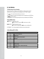
4) Error Message (In CAL Mode)
Error 20
▣ Reason
The resolution exceeds 1/10,000
☞ Solution
Lower the resolution.
The resolution = allowed weight/one division.
Modify the allowed weight in CAL1 or modify the division in CAL2 so that
the resolution is below 1/10,000
Error 22
▣ Reason
The weight for span calibration is lower than 10% of the maximum
capacity of the indicator
☞ Solution
Set the weight for span calibration in CAL 3 to be greater than 10% of the
maximum capacity
Error 23
▣ Reason
The weight for span calibration exceeds 100% of the maximum capacity
of the indicator
☞ Solution
Set the weight for span calibration to be within the maximum capacity of
the indicator in CAL 1
Error 24
▣ Reason
Span value is too low
☞ Solution
Load cell is damaged or setting of current resolution is not possible.
Calibrate with less resolution
21
Error 25
▣ Reason
Span value is too high
☞ Solution
Load cell is damaged or setting of current resolution is not possible.
Calibrate with less resolution
Error 26
▣ Reason
Zero value is too high
☞ Solution
Check whether the platter is empty
Remove the setting cover and set SW2 DIP2 to on so that the zero value is
increased. Proceed calibration again after checking in test mode 3
Error 27
▣ Reason
Zero value is too low
☞ Solution
Check whether the platter is empty.
Remove the setting cover and set SW2 DIP1 to on so that the zero value is
decreased. Proceed calibration again after checking in test mode 3
Error 28
▣ Reason
The weight is unstable
☞ Solution
Check whether load cell is properly connected
22
5) Sealing Method
① Sealing method of cal switch
② Sealing method of Load Cell Connector
23
9. Set Mode
1) How to go to set mode
Open the front cover of indicator. set SW1 DIP2 to on. Then set mode is started.
At this time, F01 message is shown on the display after “SET Mod” message.
①
: You can select the menu that you want to set
② Enter number of set menu by pressing the arrow keys and then press ENTER key.
③
: F01 is set to 1.
④ Enter number of set menu by pressing the arrow keys and then press ENTER key.
2) Availabe keys.
KEY : Change the set value.
key increases set value and
key decreases set value.
KEY : Change the position of cursor.
key moves one digit to right,
key moves one digit to left.
ENTER KEY : Save current setting value and go to menu selection mode.
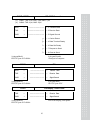
3) Set Menu(F01~F59)
General setting
F01
Decimal Point Adjustment
F02
Weighing Unit
F03
Analog to Digital Conversion Speed
F04
Digital Filter
F05
Motion Detection Condition
F06
Automatic Zero Tracking Compensation
F07
Weight Backup
F08
Set Zero Range
F09
Conditions of ZERO, TARE & START Keys
F10
Set Hold Type
24
Batching Operation Function
F11
Zero Band
F12
Optional Preliminary Weight
F13
Preliminary Weight
F14
Final Weight
F15
Free Fall Weight
F16
High Limit Weight
F17
Low Limit Weight
F18
Timer - Start Delay Time
F19
Timer - Operating Delay Time of Finish Signal
F20
Measurement Mode
F21
Timer - Start Delay Time of Finish Signal
F22
Off Range of Finish Signal
F23
A Use of "*" key
F24
A Use of ENTER key
Serial Interface (COM1, COM2)
F30
Device ID
F31
COM1 Baud Rate
F32
COM1 Usage
F33
COM1 Output Mode
F34
COM2 Baud Rate
F35
COM2 Usage
F36
COM2 Output Mode
F37
Output Format of COM1 & COM2
F38
Parity Bit
Print Function
F40
Line Feed
F41
Printer
F42
Automatic / Manual Print
F43
Printing Format
25
F44
Output the user’s message
F45
Date Change
F46
Time Change
User’s Utility
F50
Set-point input type selection
F51
Load cell type selection
F52
Buzzer On/Off selection
Options
F55
Select the Option
Analog Out (Option -1) : 4~20mA
Analog Out (Option -2) : 0~10V
F56
Output Logic of BCD Out
F57
Analog Output Adjustment at Display Zero
F58
Analog Output Adjustment at Maximum Capacity
BCD Out (Option -3) :
F01 ~ F03
F05 ~ F10
F18 ~ F24
F40 ~ F43
F50 ~ F52
These items of SET MODE are possible to be red & written from PC (Set Mode Values)
F11 ~ F17
These items of SET MODE are possible to be red & written from PC (Set Mode Values)
26
① General function
F01
FUNCTION : Decimal Point Adjustment
DISPLAY
F01
Set value
(0~3)
F01
0
1
DESCRIPTION
No Decimal Point
(ex : 12345)
10
1
(ex : 1234.5)
(ex : 123.45)
(ex : 12.345)
F01
2
10
2
F01
3
10
3
F02
FUNCTION : Weighing Unit
DISPLAY
Set value
( 0, 1 )
DESCRIPTION
F02
0
Kilogram (kg)
F02
1
Ton (t)
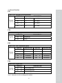
F03
FUNCTION : A/D Conversion Speed
DISPLAY
Set value
(0~9)
DESCRIPTION
DISPLAY
F03
0
20 times/sec.
F03
5
120 times/sec.
F03
1
40 times/sec.
F03
6
140 times/sec.
F03
2
60 times/sec.
F03
7
160 times/sec.
F03
3
80 times/sec.
F03
8
180 times/sec.
F03
4
100 times/sec.
F03
9
200 times/sec.
F04
FUNCTION : Digital filter
DISPLAY
Set value
( 00 ~ 99 )
DESCRIPTION
DESCRIPTION
F04
10
10 time average value
F04
50
50 times average value
F04
99
99 times average value
Note 1. Adjust the set value according to the condition.
27
F05
FUNCTION : Motion Detection Condition
DISPLAY
Set value
( 00 ~ 99 )
F05
12
F05
56
F05
88
DESCRIPTION
Stable lamp is off even with the change of only 1 division for 1
sec.
Stable lamp is on with changing of the weight below 5 division
for 3sec.
Stable lamp is on with changing of the weight below 8 division
for 4sec.
Note 1. The first digit indicates division and the second digit indicates sec.
but have to divide it into 2 on the display.
F06
FUNCTION : Automatic Zero Tracking Compensation
DISPLAY
Set value
(0~9)
DESCRIPTION
F06
0
None
F06
1
0.5 digit
F06
5
2.5 digit
F06
9
4.5 digit
Auto-zero tracking will remove small
variations automatically
F07
FUNCTION : Weight backup
DISPLAY
Set value
(0,1)
DESCRIPTION
F07
0
Weight backup is OFF
F07
1
Weight backup is ON
Note 1. Memorize the current weight at sudden power failure.
F08
FUNCTION : Set Zero Range
DISPLAY
Set value
( 0, 1 )
DESCRIPTION
F08
0
Zero key is operated within 2% of max. weight
F08
1
Zero key is operated within 10% of max. weight
28
F09
FUNCTION : ZERO, TARE & START keys Availability
DISPLAY
Set value
(0,1)
DESCRIPTION
F09
0
Always
F09
1
Works when weight is stable
F10
FUNCTION : Set Hold Type
DISPLAY
Set value
(0~2)
F10
0
F10
1
F10
2
DESCRIPTION
Average hold :
Compute the average weight of oscillating weights
Peak hold :
Compute the maximum weight among oscillating
weights
Sampling hold :
Compute the moment weight of oscillating weights.
Note 1. You have to set F23 to 2 in set mode.
Note 2. The hold function is released when it is in zero range or over load automatically.
② Batching operation function
F11
FUNCTION : Zero Band
Set zero band value which will be used in batching operation
F12
FUNCTION : Optional Preliminary Weight
Set optional preliminary weight which will be used in batching operation
F13
FUNCTION : Preliminary Weight
Set preliminary weight which will be used in batching operation
F14
FUNCTION : Final Weight
Set final weight which will be used in batching operation
29
F15
FUNCTION : Free Fall Weight
Set free fall weight which will be used in batching operation
F16
FUNCTION : High Limit Weight
Set high limit weight which will be used in batching operation
F17
FUNCTION : Low Limit Weight
Set low limit weight which will be used in batching operation
F18
FUNCTION : Timer – Start Delay Time
DISPLAY
Set value
( 00 ~ 99 )
DESCRIPTION
F18
00
No delay
F18
01
0.1 sec
F18
99
9.9 sec
F19
FUNCTION : Timer – Operating Delay Time of Finish Signal
DISPLAY
Set value
( 00 ~ 99 )
DESCRIPTION
F19
00
Do not use
F19
10
1.0 sec
F19
99
9.9 sec
Note 1. This function is used to decide the time of signal output which batching operation is
completed.
Note 2. You have to set F19 to 00 if you want to use the F22 function.
If F19 & F22 are set any values at the same time, F22 is disregarded.
Because the priority of F19 is high.
30
F20
FUNCTION : Measurement Mode
DISPLAY
Set value
(0~4)
DESCRIPTION
F20
0
Do not use.
F20
1
F20
2
Customer Programmed
Control mode
F20
3
F20
4
Built-in automatic
Program mode
Normal batching
Loss-in-Weight batching
Normal batching
Loss-in-Weight batching
F21
FUNCTION : Timer – Start Delay Time of Finish Signal
DISPLAY
Set value
( 00 ~ 99 )
DESCRIPTION
F21
00
No delay time
F21
10
1.0 sec
F21
99
9.9 sec
Note 1. This function is used to decide the delay time of start- signal of output which the batching
operation is completed
F22
FUNCTION : Off Range of Finish Signal
DISPLAY
Set value
( 00 ~ 99 )
DESCRIPTION
F22
00
F22
01
Finish signal is off when the weight is within one division
99
Finish signal is off when the weight is within ninety nine
division
F22
Do not use
Note 1. This function is used to decide the size of output signal which batching- operation is
completed.
Note 2. You have to set F19 to 00 if you want to use the F22 function.
If F19 & F22 are set any values at the same time, F22 is disregarded.
Because the priority of F19 is high
31
F23
FUNCTION : A Use of “*” key
DISPLAY
Set value
(0~2)
DESCRIPTION
F23
0
Do not use
F23
1
PRINT key
F23
2
HOLD key
Note 1. It is possible to print key (COM1 only) when the usage of COM2(F35) is to set 0.
(F35 = 0). That is, F35 is setting to printer.
F24
FUNCTION : A Use of “ENTER” key
DISPLAY
Set value
(0~2)
DESCRIPTION
F24
0
Do not use
F24
1
TOTAL PRINT key
F24
2
START key in batching operation
F24
3
STOP key in batching operation
Note 1. It is possible to print key (COM1 only)
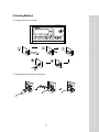
③ Serial Interface (COM1, COM2 )
Reference
RS-232C Cable
Connector
Print Key(F23=1,F24=1)
Comm. Spec.
Command
COM1(2,3,5&7)
To be set F35 = 0
TxD, RxD
Read/Write
COM2(2,5&7)
Stream,
Transmit weight when it is stable
TxD
Read
RS-422/485
Connector
Print Key(F23=1,F24=1)
COM2(6,7,8,9)
To be set F35 = 0
Comm. Spec.
TxD, RxD
32
Command
Read/Write
F30
FUNCTION : Device ID
DISPLAY
Set value
( 00 ~ 99 )
DESCRIPTION
F30
01
Device No. 01
F30
99
Device No. 99
Note 1. It is used for identification of the indicator when system is connected.
F31
FUNCTION : Baud Rate of COM1
DISPLAY
Set value
(0~5)
DESCRIPTION
F31
0
600 bps
F31
1
1200 bps
F31
2
2400 bps
F31
3
4800 bps
F31
4
9600 bps
F31
5
19200 bps
F32
FUNCTION : A Use of COM1
DISPLAY
Set value
( 0 ,1 )
DESCRIPTION
F32
0
Connection with sub-display or computer
F32
1
Connection with printer
33
F33
FUNCTION : Output Mode of COM1 (RS-232)
DISPLAY
Set value
(0~4)
DESCRIPTION
F33
0
No data output
F33
1
F33
2
F33
3
Stream mode
Transmit one time only in stable condition after
Unloading to zero
Transmit when data is required
* Signal : device ID (F31 : Device ID)
F33
4
Command Mode
Note 1. in the case of F33=3, if the Device ID is “01”, send to the “01” in the hexa mode in the
RS232C Simulator or “ALT”+”1” in the Hyper Terminal.
Note 1 : COM 1 : F33 = 4, COM2 : F35 = 1, F36 = 4 Command Mode
Command to CI-6000A
0 1 2 3 4 5 6 7 8 9 10 11
Command
description
Indicator to PC
D
ID
K
Z CR LF
ZERO key
Return the received
D
ID
K
T CR LF
TARE key
Return the received
D
ID
K
G CR LF
GROSS key
Return the received
D
ID
K
N CR LF
NET key
Return the received
D
ID
K
S CR LF
START key
Return the received
D
ID
K
P CR LF
STOP key
Return the received
D
ID
K
B CR LF
Print key
Return the received
D
ID
K
C CR LF
Total print key
Return the received
D
ID
K
W CR LF
Request weight data Return the received
D
ID
H
T CR LF
Request set-point
SEND Format 2
D
ID
H
Z
0
0
0
0
0 CR LF Zero band
Return the received
D
ID
H
O
0
0
0
0
0 CR LF Optional pre.
Return the received
D
ID
H
P
0
0
0
0
0 CR LF Preliminary
Return the received
D
ID
H
F
0
0
0
0
0 CR LF Final weight
Return the received
D
ID
H
R
0
0
0
0
0 CR LF Free fall weight
Return the received
D
ID
H
I
0
0
0
0
0 CR LF High limit weight
Return the received
D
ID
H
L
0
0
0
0
0 CR LF Low limit weight
Return the received
D
ID
H
E
0
0
0
0
0 CR LF Set-point code
Return the received
D
ID
S
T CR LF
Set Mode Value
34
SEND Format 4
(D, ID : 00~99, CR:0x0d, LF:0x0a)
It is impossible to test with Print Key ( + Total Sum Print Key) ( Only possible when F35 = 0)
■ Format 1 [ Set Point Write :: COM1/COM2 Port available ]
Write the Set-Point values to the CI-6000A with PC
- Writing(Command) & Response Format
0
1
D
17
2
ID
18
19
3
4
H
A
20
21
5
35
36
,
47
37
22
23
,
38
49
50
51
Lo Limit Weight
8
9
24
25
10
39
40
41
53
CR
LF
12
26
27
43
13
28
29
30
15
45
31
16
,
32
33
Final Weight
,
44
14
Zero Band
Hi Limit Weight
,
52
42
11
,
Preliminary Weight
Free Fall Weight
48
7
Set Point Code
Opt. Preli, Weight
34
6
46
,
Note 1 : When you input the Set Point Value, you have to input without decimal point
■ Format 2 [ Set Point Read :: COM1/COM2 Port available ]
Read the Set-Point values from CI-6000A with PC
- Command Format
0
1
D
2
ID
3
4
5
6
H
T
CR
LF
3
4
5
H
T
20
21
- Response Format
0
1
D
17
2
ID
18
19
Opt. Preli, Weight
34
35
,
47
36
37
6
22
39
Free Fall Weight
48
49
50
Lo Limit Weight
23
,
38
51
7
8
9
Set Point Code
24
25
10
26
27
Preliminary Weight
40
41
53
CR
LF
43
28
29
44
13
14
15
45
30
31
46
,
16
,
32
Final Weight
,
Note 1 : All of Set Point Values are numeric without decimal point.
35
12
Zero Band
Hi Limit Weight
,
52
42
11
,
33
■ Format 3 [ Set Mode Write :: COM1 Port only ]
Write the Set-Mode values [F01~F10, F18~F24, F40~F43, F50~F52]
from CI-6000A with PC
- Writing(Command) & Response Format
0
1
2
3
S
F
F01
F02
F03
16
17
18
19
20
21
22
30
31
32
33
34
F50
F51
F52
CR
LF
D
ID
15
F18
4
F19
5
F20
6
7
F21
8
9
F05
23
F22
10
11
12
13
14
F06
F07
F08
F09
F10
24
25
26
27
28
29
F23
F24
F40
F41
F42
F43
10
11
12
13
14
■ Format 4 [ Set Mode Read :: COM1 Port only ]
Read the Set-Mode values from CI-6000A with PC
- Command Format
0
1
D
2
ID
3
4
5
6
S
F
CR
LF
4
5
- Response Format
0
1
2
3
S
F
F01
F02
F03
16
17
18
19
20
21
22
30
31
32
33
34
F50
F51
F52
CR
LF
D
ID
15
F18
F19
F20
6
F21
36
7
8
F05
23
F22
9
F06
F07
F08
F09
F10
24
25
26
27
28
29
F23
F24
F40
F41
F42
F43
F34
FUNCTION : Band Rate of COM2
DISPLAY
Set value
(0~5)
DESCRIPTION
F34
0
600 bps
F34
1
1200 bps
F34
2
2400 bps
F34
3
4800 bps
F34
4
9600 bps
F34
5
19200 bps
F35
FUNCTION : Usage of COM2
DISPLAY
Set value
( 0 ,1 )
DESCRIPTION
F35
0
Connection with printer
F35
1
Connection with sub-display or computer
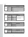
F36
FUNCTION : Output Mode of COM2 (RS-232, RS-422/485)
DISPLAY
Set value
(0~4)
DESCRIPTION
F36
0
No data output
F36
1
F36
2
F36
3
Stream mode
Transmit one time only in stable
condition after Unloading to aero
Transmit when data is required
* Signal : device ID
(F31 : Device ID)
F36
4
Command Mode
RS-232,RS-422/485
RS-232,RS-422/485
RS-422/485
RS-422/485
Note 1. COM2 connector of rear plate have two mode. One is a RS-232(F36=1, 36=2) mode.
Another is a RS-422/485 (F36=1 ~ F36=4).
Note 2. in the case of F36=3, if the Device ID is “01”, send to the “01” in the hexa mode in
the RS232C Simulator or “ALT” + “1” in the Hyper Terminal.
37
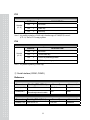
F37
FUNCTION : Output Format of COM1 and COM2
DISPLAY
DESCRIPTION
Set value
(0~2)
F37
0
F37
1
Transmit 22 byte of CAS Format
Transmit 10 byte of CAS Format
F37
2
Transmit 18 byte of AND Format
F38
FUNCTION : Parity Bit
DISPLAY
Set value
(0~2)
DESCRIPTION
F38
0
F38
1
Data bit 8, Stop bit 1, Non parity
Data bit 7, Stop bit 1, Even parity
F38
2
Data bit 7, Stop bit 1, Odd parity
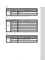
④ Printer Function
F40
FUNCTION : Line Feed
DISPLAY
Set value
(1~9)
DESCRIPTION
F40
1
1 Line feed
F40
9
9 Line feed
F41
FUNCTION : Printer
DISPLAY
Set value
(0~2)
DESCRIPTION
F41
0
Do not use
F41
1
CAS TOP printer (P202)
F41
2
CP-7000 Series Printer (CP-7000D/P, CP-7024P)
F42
FUNCTION : Automatic / Manual Print
DISPLAY
Set value
(0~1)
F42
0
Manual print
F42
1
Automatic print
DESCRIPTION
Note 1. If .F42 is set to 1, printing is done without pressing PRINT key.
It is possible to print again only after the weight is returned to zero (unload)
38
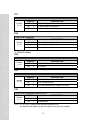
F43
FUNCTION : Printer Format
DISPLAY
Set value
(0~2)
DESCRIPTION
F43
0
Printing format 0
F43
1
Printing format 1
F43
2
Printing format 2
【 Form 0 】
Date, Time
Serial No., Net weight
【 Form 1 】
Date, Time
Serial No., Net weight
02. 1. 1
001,
002,
003,
02. 1. 1
001,
02. 1. 1
002,
02. 1. 1
003,
12:30
50.0 kg
100.0 kg
200.5 kg
----------------------------------TOTAL 350.5kg
【 Form 2 】
Date, Time
Gross weight, Tare weight,
Tare weight
12:30
50.0 kg
12:40
50.0 kg
12:50
50.0 kg
----------------------------------TOTAL 150.0kg
02. 1. 1
12:30
Gross :
1000.0 kg
Tare :
0.0 kg
Net :
1000.0 kg
02. 1. 1
12:40
Gross :
2000.0 kg
Tare :
500.0 kg
Net :
1500.0 kg
----------------------------------Net TOTAL 2500.0kg
Note 1. The serial number is initialized to 001 after total printing or power off and on.
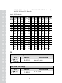
F44
FUNCTION : Input user's Information to Printing Format
Used key
:
Data
Designation *
key :
Increase
coordinate
DISPLAY
P12-065
P00-032
P18-255
DESCRIPTION
th
Set ‘A’ (ASCII code 65) in 12 data
Set blank to 0th character
This 0th code decides to print dead message.
Set 255 to 18th character.
This code indicates the end of data to be printed.
Note 1. You can add user’s information in printing format.
(Ex : Company name, phone no.)
Note 2. The range of coordinate is from 0 to 71. 0th code determines whether head message is
printed or not.(032 : print, others : Do not print) Actually 1st data to 255 is printed.
Note 3. Designate as follows if you want to add company name “CAS” on print format.
P00-032( ASCII code 32 : Data start), P01-067( ASCII code 67 : character C)
39
P02-065( ASCII code 65 : character A),P03-083( ASCII CODE 83 :character S)
P04-255( ASCII code 255: Data end)
Note 4. ASCII code table
CHA CODE CHA CODE CHA CODE CHA CODE CHA CODE CHA CODE
SPACE
32
0
48
@
64
P
80
`
96
p
112
!
33
1
49
A
65
Q
81
a
97
q
113
“
34
2
50
B
66
R
82
b
98
r
114
#
35
3
51
C
67
S
83
c
99
s
115
$
36
4
52
D
68
T
84
d
100
t
116
%
37
5
53
E
69
U
85
e
101
u
117
&
38
6
54
F
70
V
86
f
102
v
118
‘
39
7
55
G
71
W
87
g
103
w
119
(
40
8
56
H
72
X
88
h
104
x
120
)
41
9
57
I
73
Y
89
i
105
y
121
*
42
:
58
J
74
Z
90
j
106
z
122
+
43
;
59
K
75
[
91
k
107
{
123
,
44
<
60
L
76
\
92
l
108
|
124
-
45
=
61
M
77
]
93
m
109
}
125
.
46
>
62
N
78
^
94
n
110
~
126
/
47
?
63
O
79
_
95
o
111
END
255
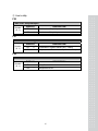
F45
FUNCTION : Date Change
KEY
key
: Enter Data
DISPLAY
02.01.10
DESCRIPTION
JAN. 10TH, 2002
F46
FUNCTION : Time Change
KEY
key
: Enter Data
DISPLAY
11.30.10
40
DESCRIPTION
11 : 30 : 10 AM
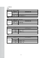
⑤ User’s utility
F50
FUNCTION : Set-point Input
Set value
(0,1)
DISPLAY
DESCRIPTION
F50
0
Disable external Set-point input
F50
1
Enable external Set-point input
F51
FUNCTION : Load cell type
Set value
(0,1)
DISPLAY
DESCRIPTION
F51
0
Compression or Tension Load cell ( 0mV ~ +40mV)
F51
1
Compression and Tension Load cell (-- 20mV ~ +20mV)
F52
FUNCTION : Buzzer On/Off
Set value
(0,1)
DISPLAY
DESCRIPTION
F52
0
Always Buzzer is ON.
F52
1
Always Buzzer is OFF.
41
⑥ Options
F55
FUNCTION : Select of Option
DISPLAY
Set value
(0,2)
DESCRIPTION
F55
0
Do not use
F55
1
Analog Out(Option – 1,2)
F55
2
BCD Out(Option – 3)
F56
FUNCTION : Output Logic – BCD Out
Set value
(0,1)
DISPLAY
DESCRIPTION
F56
0
Positive Logic
F56
1
Negative Logic
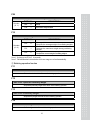
F57
FUNCTION : Analog Output Adjustment at Display Zero
DISPLAY
Set value
( 0~4000 )
DESCRIPTION
L 00000
0mA,
0V
L 04000
4.000mA, 2V
L 04015
4.015mA, 2.007V
F58
FUNCTION : Analog Output Adjustment at Maximum Capacity
DISPLAY
Set value
( 0~24000 )
DESCRIPTION
H 10000
10mA,
H 20000
20.000mA, 8.33V
H 24000
24.000mA, 10V
42
4.16V
10. Test Mode
1) How to go to Test Mode
Open the front cover of indicator. set SW1 DIP3 on.
①
: Select test menu that you wish to test.
② Please select test menu with arrow keys and press ENTER key.
③
: Test menu is selected. Proceed key test.
④ When test is done, Press ENTER key.
To finish test mode, set DIP3 off.
2) Test Menu (TEST 1 – TEST 8)
TEST 1 : Key test
TEST 2 : VFD display test
TEST 3 : A/D conversion test
TEST 4 : Serial interface test (COM1, COM2)
TEST 5 : Printer test (COM2)
TEST 6 : External input/output test
TEST 7 : Analog Out Test(Option)
TEST 8 : BCD Out Test(Option)
TEST 1
FUNCTION : Key test
KEY
DISPLAY
DESCRIPTION
ENTER: Go to menu
Selection mode
tESt
1
TEST 1 condition
Other keys : Perform test
1
1
Press any key to test then the display
shows its number and code.
Note 1. External input key test is TEST 6.
< Key list >
KEY
NO.
CODE
KEY
NO.
CODE
KEY
NO.
CODE
ZERO
1
1
TARE
2
2
K.T
3
3
G/N
4
4
*
5
5
ENTER
6
6
43
TEST 2
FUNCTION : Display test
KEY
DISPLAY
ENTER: Go to menu
Selection mode
tESt
Other keys : Perform test
8888888
2
DESCRIPTION
TEST 2 condition
TEST 2 is performed
TEST 3
FUNCTION : A/D Conversion test
KEY
: Change gain.
: Change filter
ENTER: Go to menu
Selection mode
DISPLAY
tESt
3
97853
DESCRIPTION
TEST 3 condition
Shows digital value of current weight.
This value means converted digital value.
Note 1. Check whether digital value is changing. If the digital value is fixed or zero is
displayed, please check the connection of load cell.
TEST 4
FUNCTION : RS-232C test with computer (COM1)
KEY
: Transmit to PC
after increasing
value.
: Transmit to PC
after increasing
value
ENTER: Go to menu
Selection mode
DISPLAY
tESt
4
DESCRIPTION
TEST 4 condition
00------00
Wait for transmission and reception
03------00
Transmit : 3, Receive : none
08------49
Transmit : 8, Receive : 1
Note 1. Do this test in Hyper Terminal of PC after the connecting serial port with PC.
- Port Selection in Hyper Terminal has the Flow Control item, you have to set nothing.
Note 2. Send no.1 in computer keyboard and check if indicator receives no.49
Send no.8 in indicator key( ) and check if computer receives no.8
Note 3. Baud rate should be specified in SET mode before testing.(F31)
44
TEST 5
FUNCTION : Printer test (COM1)
KEY
ENTER: Go to menu
Selection mode
Other keys : Perform test
DISPLAY
tESt
DESCRIPTION
5
TEST 5 condition
Good
No error in printer.
Note 1. Please set F35 to 0 in SET mode.
Note 2. Please set F41(the kind of printer) in SET mode.
Note 3. “Good” message is displayed if the printer connection is done correctly.
Note 4. The test output format of printer is as follows:
Computer Aided System
CAS Corporation
TEL 82-2-2225-3500
FAX 82-2-475-4668
TEST OK
TEST 6
FUNCTION : External input /output test
KEY
: Move external
Output
External input :
Shows external key
ENTER: Go to menu
Selection mode
DISPLAY
tESt
DESCRIPTION
6
TEST 6 condition
In1 : If you press 1, 1 is displayed
oUt3 : Indicate the condition of external
output.
Output no.3 is On.
In1oUt3
45
TEST 7
FUNCTION : Analog Output Test
KEY
: Output high value
(20mA)
: Output high value
(20mA)
ENTER: Go to menu
Selection mode
DISPLAY
tESt
Hi
7
Lo
DESCRIPTION
TEST 7 condition
▲(Hi) (Lo) ▼
HiGH : Output maximum weight.
(Adjust to 20mA)
ZEro : Output zero value
(Adjust to 4mA)
HiGH
Zero
TEST 8
FUNCTION : BCD Output Test
KEY
: All output is ON
: All output is OFF
ENTER: Go to menu
Selection mode
DISPLAY
DESCRIPTION
tESt
8
ALL
ON
The state of All Output is ON (Defult)
ALL
OFF
The state of All Output is OFF
46
TEST 8 condition
11. Weighing Mode
1) How to move
Turn POWER switch on, and you will go to the Weighing Mode.
2) Available keys
KEY
DESCRIPTION
1. Used to remove small variations in the indicator’s zero.
1. Used to weigh an item by using the container.
2. Save tare weight and shows net weight.
1. Used to enter tare weight manually
2. If you press this key, “t 00000” is shown on the display.
3. Enter tare weight with arrow keys and save it by pressing the
ENTER key.
1. Toggles between gross weight and net weight
2. You can prohibit using of keyboard by pressing G/N key for 4 sec
to use keyboard again, press G/N key for 4 sec
1. “*” is used in various way.
2. Used to input the set-point value for batching operation
(Press * key for 2 seconds)
3. You can select this key’s function in SET mode F23.
0. Do not use.
1. PRINT Key.
2. HOLD Key.
1. ENTER key is used in various way.
2. You can select this key’s function in SET mode F24.
0. Do not use
1. TOTAL PRINT key.
2. START key for batching operation
3. STOP key for batching operation
3. Set set-point code for batching operation.(00~49)
(Press the ENTER key for 2 sec.)
47
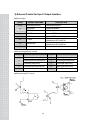
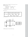
3) External Control for Input / Output Interface
■ External input
Pin No.
24, 25
SIGNAL LINE NAME
DESCRIPTION
GND (Input common)
External input common
16
ZERO input
ZERO key operation
17
TARE input
TARE key operation
18
START input
Used as START key in batching operation
19
STOP input
20
“*” input
21
ENTER input
Used as STOP key in batching operation
“*” is used in various way
(Set this key in SET mode F23)
“*” is used in various way
(Set this key in SET mode F24)
22, 23
Buffer
Enable to add the Key function
■ External output (Relay contact)
Pin No.
SIGNAL LINE NAME
Pin No.
SIGNAL LINE NAME
3
Zero band signal output (Out 1)
7
High limit signal output (Out 5)
4
Optional preliminary output (Out 2)
8
Low limit signal output (Out 6)
5
Preliminary output (Out 3)
9
Finish signal output (Out 7)
Final weight signal output (Out 4)
10
Stable signal output (Out 8)
6
11, 12
Output common
■ External control I/O circuit
48
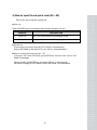
4) How to input the set-point code (00 ~ 49)
There are two ways to input the set-point code
■ First way
Press the ENTER key for 2 seconds to enter set-point (Set-point : 00~49)
DISPLAY
DESCRIPTION
Code = 00
Set – point Code Number=00 in weighing control
Code = 49
Set – point Code Number=49 in weighing control
■ Second way
You can enter set-point by using RS-232C, RS-485 Communication
Refer to SET Mode. (In the case of F33 = 4 or F36 = 4, Command Mode )
■ How to clear the Set-Point value (00 ~ 49 )
After input “F88” in the SET Mode, press ENTER key and can see the “Factor” and
“0000” on the display
After input “2007” and ENTER key, can see the “SP init”. In a few seconds,
can see the message of “End” and then exit the SET Mode. It is accomplished
49
5) How to input the set-point value
There are four ways to input the set-point value
■ First way (F50 = 0 )
To enter set-point, press the * key for 2 seconds in weighing mode
Note 1. Set F50 to 0 in set mode
Note 2. Shift the position of cursor with
,
key and enter set value with
,
key to
go to next step, press the * key
STEP
DISPLAY
STEP1
ZEro bA
DESCRIPTION
Zero Band
Shift the position of cursor with , key and
, key
Enter Zero band value with
To go to next step, press the * key
Point
1 - 00000
STEP2
STEP3
STEP4
STEP5
STEP6
STEP7
oP - Pre
Optional Preliminary
Input first weight
2 - 00000
PrELiM
Preliminary weight
Input Preliminary weight
3 - 00000
FinAL
Final weight
Input final weight
4 - 00000
FALL
Free Fall Weight
Input free fall weight
5 - 00000
H - LiMit
High Limit Weight
Input high limit weight
6 - 00000
L - LiMit
Low Limit Weight
Input low limit weight
7 - 00000
■ Second way (F50 = 0 )
Enter set value from F1 to F17 in set mode.
F11 : Zero Band
F12 : Optional Preliminary Weight
F13 : Preliminary Weight
F14 : Final Weight
F15 : Free Fall Weight
F16 : High Limit Weight
F17 : Low Limit Weight
■ Third way
Enter set-point by using RS-232, RS-485 Communication
Set F33 to 4 in set mode. Refer to set mode. (F33)
50
6) Set-point Condition
Output is done according to the following condition in batching operation.
MODE
COMMON
NORMAL
Loss – in
COMMON
COMMON
COMMON
COMMON
OUTPUT
Zero band output
Optional preliminary
weight output
Optional preliminary
weight output
Preliminary
weight output
Final weight
Output
High limit weight
Output
Low limit weight
Output
CONDITION
GROSS weight ≤ Zero band
NET weight ≥ Final weight – Optional preliminary weight
GROSS weight > Optional preliminary weight
NET weight ≥ Final weight - Preliminary weight
NET weight ≥ Final weight - Free fall weight
NET weight > Final weight + High limit weight
NET weight < Final weight - Low limit weight
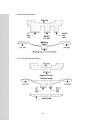
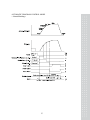
7) Batching Operation
You can select batching operation method in set mode, F20.
a. USER PROGRAM CONTROL MODE
■ Normal Batching
■ Loss-in-Weight Batching
b. AUTOMATIC PROGRAM CONTROL MODE
■ Normal Batching
■ Loss-in-Weight Batching
51
< Normal Batching Diagram >
< Loss-in-Weight Batching Diagram >
52
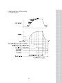
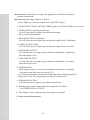
USER PROGRAM CONTROL MODE
< Normal Batching >
53
■ You can operate external control for your needs in user program control mode.
■ External input and output signal is as follows.
1. Press TARE key so that the display shows 0kg (NET weight).
2. FIRST OUTPUT(Optional preliminary) :
It is ON when the net weight is greater than the weight
(Final - Optional preliminary).
3. SECOND OUTPUT(Preliminary) :
It is ON when the net weight is greater than the weight (Final - Preliminary).
4. THIRD OUTPUT(Final) :
It is ON when the net weight is greater than the weight (Final - Free fall).
5. HIGH LIMIT OUTPUT :
It is ON when the net weight is greater than the weight (Final + High limit)
after third output is ON.
6. LOW LIMIT OUTPUT :
It is ON when the net weight is greater than the weight (Final - Low limit)
after third output is ON.
7. FINISH SIGNAL :
When weight is stable, It is ON after passing the certain time of start delay
(You can set start delay time in set mode, F21.)
It is OFF after passing the certain time of operating delay or Finish Signal OFF
Range (F22). (You can set operating delay time in set mode, F19.)
8. ZERO BAND OUTPUT :
It is ON when gross weight is lower than zero band value.
9. Discharge gate control signal is not supplied in CI-6000A.
- Use FINISH SIGNAL OUTPUT.
10. Prepare for next batching operation.
54
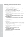
USER PROGRAM CONTROL MODE
< Loss-in-Weight >
55
■ You can operate external control for your needs in user program control mode.
■ External input and output signal is as follows.
1. FIRST OUTPUT(Optional preliminary) :
It is ON when the gross weight is greater than optional preliminary weight.
It is OFF when the gross weight is lower than final weight.
- Fill in the hopper by using first output signal.
2. Press TARE key so that the display shows 0kg (NET weight).
3. SECOND OUTPUT(Preliminary) :
It is ON when the net weight is greater than the weight (Final - Preliminary).
4. THIRD OUTPUT(Final) :
It is ON when the NET weight is more than the weight (Final - Free fall).
5. HIGH LIMIT OUTPUT :
It is ON when the net weight is greater than the weight (Final + High limit)
after third output is ON.
6. LOW LIMIT OUTPUT :
It is ON when the net weight is greater than the weight (Final - Low limit)
after third output is ON.
7. FINISH SIGNAL :
When weight is stable, It is ON after passing the certain time of start delay
(You can set start delay time in set mode, F21.)
It is OFF after passing the certain time of operating delay or Finish Signal OFF
Range (F22). (You can set operating delay time in set mode, F19.)
8. ZERO BAND OUTPUT :
It is ON when the gross weight is lower than zero band value.
9. Discharge gate control signal is not supplied in CI-6000A.
- Use FINISH SIGNAL OUTPUT.
10. Prepare for next batching operation.
56
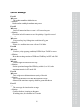
AUTOMATIC PROGRAM CONTROL MODE
< Normal Batching >
57
■ Output/input is controlled according as the program of an indicator in utomatic
program control mode.
■ External input and output signal is as follows.
1. Press TARE key so that the display shows 0kg (NET weight).
2. START INPUT: FIRST, SECOND, THIRD output is ON when START key is pressed.
3. FIRST OUTPUT (Optional preliminary) :
It is OFF when the net weight is greater than the weight
(Final - Optional preliminary).
4. SECOND OUTPUT (Preliminary) :
It is OFF when the net weight is greater than the weight (Final - Preliminary).
5. THIRD OUTPUT (Final) :
It is OFF when the net weight is greater than the weight (Final - Free fall).
6. HIGH LIMIT OUTPUT :
It is ON when the net weight is greater than the weight (Final + High limit)
after third output is ON.
7. LOW LIMIT OUTPUT :
It is ON when the net weight is greater than the weight (Final - Low limit)
after third output is ON.
8. FINISH SIGNAL :
When weight is stable, It is ON after passing the certain time of start delay.
(You can set start delay time in set mode, F21.)
It is OFF after passing the certain time of operating delay or Finish Signal OFF
Range (F22). (You can set operating delay time in set mode, F19.)
9. ZERO BAND OUTPUT :
It is ON when gross weight is lower than zero band value.
10. Discharge gate control signal could not be supplied in CI-6000A.
- Use FINISH SIGNAL OUTPUT.
11. Data Output : Data is outputted after finish signal is outputted.
12. Prepare for next batching operation.
58
AUTOMATIC PROGRAM CONTROL MODE
< Loss-in-Weight >
59
■ Output/input is controlled according as the program of an indicator in
automatic program control mode.
■ External input and output signal is as follows.
1. FIRST OUTPUT (Optional preliminary) :
It is ON when the gross weight is greater than optional preliminary weight.
It is OFF when the gross weight is lower than final weight.
- Fill in the hopper by using first output signal.
2. Press TARE key so that the display shows 0kg (NET weight).
3. START INPUT: FIRST, SECOND, THIRD output is ON when START key is pressed.
4. SECOND OUTPUT (Preliminary) :
It is OFF when the net weight is greater than the weight (Final - Preliminary).
5. THIRD OUTPUT(Final) :
It is OFF when the net weight is greater than the weight (Final - Free fall).
6. HIGH LIMIT OUTPUT:
It is ON when the net weight is greater than the weight (Final + High limit)
after third output is ON.
7. LOW LIMIT OUTPUT:
It is ON when the net weight is greater than the weight (Final - Low limit)
After third output is ON.
8. FINISH SIGNAL:
When weight is stable, It is ON after passing the certain time of start delay. (You
can set start delay time in set mode, F21.)
It is OFF after passing the certain time of operating delay or Finish Signal OFF
Range (F22). (You can set operating delay time in set mode, F19.)
9. ZERO BAND OUTPUT: It is ON when gross weight is lower than
zero band value.
10. Discharge gate control signal is not supplied in CI-6000A.
- Use FINISH SIGNAL OUTPUT.
11. Data Output : Data is outputted after finish signal is outputted.
12. Prepare for next batching operation.
60
8) Error Message
Error 01
▣ Reason
The weight is unstable to initialize the scale
☞ Solution
Put the scale on a stable place and turn on the power
Error 02
▣ Reason
Load cell connection failure or error in A/D conversion part.
☞ Solution
Check the load cell connector to see if the polarity of signal is reversed
Error 05
▣ Reason
You pressed any key for long time or problem of key part
☞ Solution
If there is no problem in key part, call your CAS dealer
Error 08
▣ Reason
You have set the operating condition of ZERO key or TARE key not to
operate when the indicator is not stable.
☞ Solution
Reset the operating condition of ZERO and TARE key in SET mode F09
Error 09
▣ Reason
Current weight deviates from zero range
☞ Solution
Set the operational range of the ZERO key within 2% or 10% of the
maximum capacity in SET mode F08
Error 10
▣ Reason
Tare weight exceeds the maximum capacity of the scale
☞ Solution
Tare weight should be lower than the maximum capacity.
Otherwise, the maximum capacity should be greater than the tare
Error 13
▣ Reason
The zero range deviates from the set range
☞ Solution
Confirm that there is nothing on the platter.
If nothing exists, do calibration in CAL mode
61
Error 14
▣ Reason
Gross weight is lower than final Weight in Loss-in-weight batching of
Built-in automatic program mode
OVER
▣ Reason
The weight is exceeds maximum capacity of the indicator
☞ Solution
Do not load the item exceeds the maximum tolerance.
If the load cell is damaged, the load cell should be replaced
62
12. Serial Interface (COM1, COM2)
COM1,COM2
F30
Baud Rate
Device ID
00 ~ 99
COM1
Transmission Mode
F31
Baud Rate
F32
A Use of COM1
F33
Output Mode
600, 1200, 2400, 4800, 9600, 19200 bps
Printer, Sub-display or Computer
Stream, Stable, Data is required, Command mode
COM2
Transmission Mode
F34
Baud Rate
600, 1200, 2400, 4800, 9600, 19200 bps
F35
A Use of COM2
Printer, Sub-display or Computer
F36
Output Mode
Stream, Stable, Data is required,
Command mode
COM1,COM2
F37
Data Format
Data Out Format
22bytes and 10bytes of CAS, 18bytes of AND
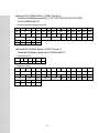
①. 22 bytes of CAS
- Data bit : 8, Stop bit : 1, Parity bit : None
- Code : ASCII
- When the data is sent to computer?
Select in SET mode
■ Transmit always : 1 is selected in F33, F36.
■ Transmit when weight is stable : 2 is selected in F33, F36.
■ Transmit when data is required : 3 is selected in F33, F36.
Indicator print output format when computer transmits 1 byte of device ID to an indicator.
- Transmission data format (22 BYTE)
.
└──┘
.
└──┘
DATA (8byte)
.
│
└──────┐
US(Unstable) GS(GROSS weight) Device ID
ST(Stable)
NT(NET weight)
OL(Overload)
Lamp condition byte
63
CR
│
└──┘
Empty Unit (kg/t)
LF
- Device ID : Transmit 1 byte of device ID so that the receiver can receive data
selectively which indicator send.(Device ID is set in F30 .)
- Lamp condition byte : Indicate on/off
Bit 7
Bit 6
Bit 5
Bit 4
Bit 3
Bit 2
Bit 1
Bit 0
1
Stable
0
Hold
Print
Gross
Tare
Zero
- Data(8 byte) : If 13.5kg, Each ASCII code ‘0’, ‘0’, ‘0’, ‘0’, ‘1’, ‘3’, ‘.’, ‘5’
is transmitted by 8 byte.
- Output error message
Byte 1
Byte 2
Byte 3
E
R
R
Byte 4
Byte 5
Byte 6
Byte 7
Error code
② 10 bytes of CAS
- Data bit : 8, Stop bit : 1, Parity bit : None
- Code : ASCII
- Transmission data format (10 BYTE)
DATA (8 byte)
CR
LF
③ 18 bytes of AND
- Data bit : 8, Stop bit : 1, Parity bit : Even
- Code : ASCII
- Transmission data format (18 BYTE)
.
└──┘
.
DATA (8byte)
└──┘
CR
└──┘
US(Unstable) GS(GROSS weight)
ST(Stable)
NT(NET weight)
OL(Overload)
Unit (kg/t)
64
LF
Byte 8
Byte 9
CR
LF
COM1, COM2
(1)
(2)
RS-232C Connection
COM1 - TXD : 2 pin, RXD : 3 pin, GND : 7 pin
COM2 - TXD : 2 pin, GND : 5 pin
RXD
ㅇ
-----------------------------
ㅇ 3 Transmit Data
TXD
ㅇ
-----------------------------
ㅇ 2 Receive Data
GND
ㅇ
-----------------------------
ㅇ 5 Signal Ground
┌─
ㅇ 1 Carrier Detect
├─
ㅇ 4 Data Terminal Ready
└─
ㅇ 6 Data Set Ready
┌─
ㅇ 7 Request to Send
└─
ㅇ 8 Clear to Send
9 pin port(Male)
RS-232C port of Cl-6000A
9 pin port(Female)
Serial port of computer
COM1
PC
RXD
ㅇ
-------------------------
ㅇ
Transmit Data
TXD
ㅇ
--------------------------
ㅇ
Receive Data
GND
ㅇ
--------------------------
ㅇ
Signal Ground
9 pin port(Male)
RS-232C port of Cl-6000A
9 pin port(Male)
RS-232C port of PC
COM2
Sub-display, Serial Printer
TXD
ㅇ
--------------------------
ㅇ
Receive Data
GND
ㅇ
--------------------------
ㅇ
Signal Ground
9 pin port(Male)
RS-232C port of Cl-6000A
Port of sub-display, serial printer
65
COM2
RS-422 Connection
COM 2 - OUT (+)
IN(+)
: 8pin,
: 6pin,
OUT(-) : 9pin
IN(-)
: 7pin
- Transfer Mode : Same to the RS-232C interface
F30
Device ID
00 ~ 99
F34
Baud Rate
600,1200,2400,4800,9600,19200bps
F36
Output Mode
Stable, Stable or Unstable, Command mode
Data Format : Same to the RS-232C interface(Only Tx of Indicator)
- How to connect to the RS-485 port
Rx(+):IN(+)⑥
---┒
Tx(+):OUT(+)⑧
---┚
DATA +
( TRX +)
-----------RS –
232C
Rx(-):IN(-) ⑦
---┒
Tx(-):OUT(-)⑨
---┚
9pin port (Male)
PC
------------
DATA ( TRX -)
RS-485
Convertor
RS-485 port of CI-6000A
- How to connect to the RS-422 port
TX+ :Out(+)
⑧
-------
Rx+
TX- :Out(-)
⑨
-------
Rx-
RS-
----------------
RX+ : IN(+)
⑥
-------
Tx+
232C
----------------
RX- : IN(-)
⑦
-------
Tx-
PC
9pin port (Male)
RS-422 Convertor
RS-422 port of CI-6000A
66
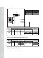
13. OPTIONS
OP-1
Analog Output Interface (Current Output)
■ Set F56 to 1 in set mode.
■ Specification
4 – 20mA, 0 – 20mA, 0 – 24mA
Output Current
More than 1/2000
Resolution
Temperature Coefficient
0.01%
Maximum Load Resistor
500Ω MAX.
■ When the display weight is "0", the output current is 0mA or 4mA.
When the display weight is maximum capacity of the indicator, the output current is
20mA or 24mA.
■ To use current to voltage
If you add a 250Ω shunt resistor, voltage output will be 1 - 5V or 0 – 5V or 0 – 6V.
(250Ω * 4mA ∼ 250Ω * 20mA)
+ 15V
HI
LO
Shunt Resistor
67
■ Switch setting
SW1
1
0
1
Fixing or Flexibility
Fixing
Setting
SW2
1
1
0
Set Mode
SW4
SW5
SW1
SW2
0
0
1
1
Output
0 – 24mA
0 – 20mA
4 – 20mA
Output
Current
F57(Min)
F58(Max)
4000
20000
4 – 20mA
0000
20000
0 – 20mA
0000
24000
0 – 24mA
When you use the Fixing Mode (SW4=SW5=0),
you have to set one(1) of the SW1 & SW2 and
you have to set the values what you want to out in the SET MODE (F57 & F58)
Fixing or Flexibility
Flexibility
SW4
SW5
1
1
Setting
Set Mode
SW1
SW2
1
1
0
1
1
0
F57(Min)
F58(Max)
0000
24000
0 – 24mA
When you use the Flexibility Mode (SW4=SW5=1),
you select to set the setting switches what you want to out
If the output current is not correct, you need to adjust the volume resistors of VR1 & VR2.
VR1 is used to adjust to zero value. VR2 is used to adjust to Max. value.
68
Output
Current
0 – 20mA
4 – 20mA
OP-2
Analog Output Interface (0-10V)
■ Set F56 to 1 in set mode.
■ Specification
0 – 10V
Output Voltage
More than 1/2000
Resolution
Temperature Coefficient
0.01%
■ The output voltage is 0V when the display weight is "0".
And the output voltage is 10V when the display weight is maximum capacity of the indicator.
SW1
0
Fixing or Flexibility
Flexibility
Setting
SW2
0
Set Mode
SW4
SW5
SW1
SW2
F57(Min)
F58(Max)
0
0
0
0
0000
24000
You have to set zero(0) of the SW1, SW2, SW4 and SW5
69
Output
0 – 10V
Output
Current
0 – 10V
OP-3
BCD Output Interface
Parallel BCD output is the interface that transmits the weight as BCD code.
Inner circuit of input/output circuit is electronically disconnected by photo-coupler
■ Set F55 to 2 in set mode.
■ Transmission mode
F56
Output Logic
Positive Logic, Negative Logic
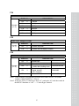
■ Pin Connection
PIN
1
SIGNAL
Ground (GND)
PIN
26
SIGNAL
High : Net, Low : Gross
2
1 x 10
0
3
2 x 10
27
N.C.
0
28
4
4 x 10
N.C.
0
29
5
8 x 10
N.C.
0
30
6
1 x 10
N.C.
1
31
N.C.
1
32
N.C.
1
33
N.C.
1
34
N.C.
2
35
N.C.
2
36
N.C.
2
37
External Vcc
2
38
N.C.
3
39
External Vcc
3
40
N.C.
3
41
N.C.
3
42
High : +, Low : -
4
43
Decimal point : 10
4
44
Decimal point : 10
4
45
Decimal point : 10
4
46
Over Load
5
47
N.C.
5
48
N.C.
5
49
Busy
5
50
7
2 x 10
8
4 x 10
9
8 x 10
10
1 x 10
11
2 x 10
12
4 x 10
13
8 x 10
14
1 x 10
15
2 x 10
16
4 x 10
17
8 x 10
18
1 x 10
19
20
2 x 10
4 x 10
21
8 x 10
22
1 x 10
23
2 x 10
24
4 x 10
25
8 x 10
70
1
2
3
■ 50 pin connector : CHAMP 57-40500(Amphenol) Female
■ TTL Open-Collector Output
■ SIGNAL LOGIC
1. BCD data output : Positive, Negative logic
2. Polarity output : “+” = High
3. OVER output
: “OVER" = High
4. BUSY output
: “BUSY” = High
■ Standard Accessory :
Mating connector 57-30500(Amphenol) Male 1EA.
■ Weight Data
WEIGHT DATA
BUSY SIGNAL
■ BCD output circuit
+V
Voltage
+V
+V
CI-6000A1
■ BCD output circuit is Open Collector Type.
71
30V max.
Current
30mA max.
Output Voltage
when ON
0.2V Txp
MEMO
72
MEMO
73
MEMO
74
75