1
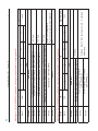
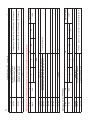
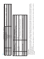
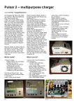
www.lowcarbon-idea.com
[email protected]
Manual 8kW
User’s Manual
8kW Fast Charging Battery Charger
With CAN interface
IGBT power modules inside
P.1
www.lowcarbon-idea.com
[email protected]
Manual 8kW
contents
Overview......................................................................................................................P3
Performance................................................................................................................P4
Specification.................................................................................................................P5
Front operation panel...................................................................................................P6
Rear operation panel...................................................................................................P7
Inner structure & packing.............................................................................................P8
P.2
www.lowcarbon-idea.com
[email protected]
Manual 8kW
Overview
This smart charger for electric vehicle uses high-frequency switching power supply technology, which
learn from and absorb the advanced control technology designed. It is a practical, functional and reliable
products.This electric vehicle charger is light weight, small size, charge stability, high efficiency,
anti-seismic capability, safety and reliability. And it has under voltage, over voltage, reverse polarity,
short circuit, overload protection. Curve with a reasonable charge and SCM control the charging process
to ensure that the battery is fully charged, and extend the battery life.
The principle of introduction:
This charger apply full bridge rectification principle. AC input rectifier bridge for the first time into the
rectifier filter, resulting in a smooth DC voltage, and the DC voltage through full bridge inverter, generate
high frequency AC signal, then the high-frequency alternating current after the second rectifier filter,
produces a smooth DC.
65C thermal protection
AC input
DC output
Control PCB
First filtering
First rectify
Second rectify
Second filtering
P.3
Full bridge convert
www.lowcarbon-idea.com
[email protected]
Manual 8kW
The charge curve
Charging process description:
1.Preconditioning Charge: when charging machine starts, first 3-5A charging current for four minutes,
and then high current charging. Four minutes is a small current to activate the battery charging purposes
the chemical reaction inside the battery fully established, to avoid charging the battery in the cold state;
2.After four minutes the end of a small current, the charging unit into the preset current (eg 20A) constant
current charging phase. When the voltage charge to a preset voltage (eg 400V), the charger reduces the
charge without entering the voltage constant current value of the stage. Since then continue to detect the
charging voltage, when the battery voltage again reaches 400V, the charger reduces the charge current
once again (each time decreasing 2A), repeatedly until the charging current over the charging process to
2A, the charger that the battery is fully charged and shut down;
3. Charging authorities in the no-load machine just off the charge rather than the whole state down.
P.4
www.lowcarbon-idea.com
[email protected]
Manual 8kW
Working conditions:
1. Suitable the battery type: Lead-acid battery, Li-FePO4 battery, NI-MH battery.
2. Altitude: not exceeding 1,200 m.
3. Ambient temperature: -20 °C ~ +50°C .
4. Relative humidity: 30%~90%.
5. To ensure placement in the No explosive material charge location, there is no corrosion of metal and
insulation damage to the gas or steam, dry and ventilated environment.
6.No severe vibration and shock, the vertical gradient of not more than 5%.
7.the grid voltage fluctuation range of continuing convergence value does not exceed the rated ± 5%,
short-term fluctuations (less than 1 second) does not exceed 10% of the fundamental peak
instantaneous volatility of not more than 20%.
Features:
1.According to the design characteristics of the battery charge a reasonable curve, both full of batteries
and can extend battery life.
2.Easy to use, simple maintenance, intelligent charging, without human duty.
3.the protection function. Over voltage, under voltage, over current, over heating, short circuit, output
reverse polarity protection, etc.
4.Intuitive and strong. Charging process and the failure by the LCD screen display, can at a glance.
5.Using high-frequency soft switch technology, making the charger and high efficiency, small size, light
weight.
6.Charger fan switch control by the temperature 45 °C, when the radiator temperature is below 45 °C, the
fan does not rotate. When the radiator temperature is higher than 45 ? , the fans began to turn, can
reduce noise and extend fan life.
The major technical specification:
1) The input is AC380V (three-phase three-wire);
2) Input voltage and frequency to adapt to wide range of power in the AC 380V ± 10%, and frequency of
50Hz ± 10% enter the work can be stable and reliable;
3) DC output value from 40-400V continuously adjustable.
4) Output DC Current value from 5-20A potentiometer continuously adjustable;
5) Load regulation: ≤ 1%;
6) voltage regulation rate: ≤ 1% load regulation: ≤ 1%;
7) Ripple Voltage: ≤ 1%;
8) Leakage current: ≤ 10mA;
9) Duty cycle: 100%;
10) the overall efficiency: ≥ 92% (full load);
11) Power factor: ≥ 0.80 (full load);
12) Insulation resistance: DC1000V test ≥ 50MΩ;
13) Charging Mode: Auto + Manual;
14) With charging voltage, current, charge status, display and parameter setting functions;
15) With failure alarm and display;
16) With pre-constant current charging, constant voltage float late, full auto-stop function;
17) Protection class: IP32;
18) Cooling: Air Cooled;
19) With the protection function of fatal error (such as load reverse polarity, input and output short circuit)
P.5
www.lowcarbon-idea.com
[email protected]
Manual 8kW
shutdown, the general error alarm function;
20) With over voltage, under voltage, over current, over heating, lack phase, corresponding to
short-circuit protection;
Front operation panel
Front operation panel introduction
ON / OFF switch: When to start charging machine, please switch to the ON position, when the charger
need to turn off, please the switch to the OFF position.
REMOTE / LOCAL: When the switch to the REMOTE position, the charger from the CAN control,
manual operation is not Work; when the switch on the LOCAL position: CAN communication cut off,
charging into the machine by manual operation way.
SET / WORK: When the manual operation, first press the SET switch position, the voltage and current
values can be set manually. When the voltage and current value finish setting, put the switch to the
WORK position to start charging machine according to previous setting .
VOLAGE (V): Display the actual output of charging voltage value.
CURRENT (A): Display the actual output current work.
VOLTAGE: Voltage adjustment potentiometer to change the voltage value.
CURRENT: Current adjustment potentiometer to change the current value.
BATTREY: This LED will be light after the battery connections correctly.
CHARGE: When charging is normal this LED will be light.
ERROR: When the reverse or short circuit
P.6
www.lowcarbon-idea.com
[email protected]
Manual 8kW
Rear operation panel introduction
40
0m
m
390mm
300mm
AC INPUT: AC 3-phase 380V;
OUTPUT: DC output, the red terminal is positive, the black terminal is negative;
CAN: CAN communication, 1 foot (red line) is high, 2 feet (black line) is low.
Wiring connection:
1.Firstly, take the charger and the battery connected, the red terminal is positive output, access to
battery positive, black-side output is negative, access to the battery negative.
2.the AC input connected, the input for the three-phase 380V, three-phase for the firing line, there is no
zero line.
3.Please take a good ground to avoid danger.
4.Turn on the AC switch, charger start.
Operation option
1.Firstly, open the voltage switch, then select the charging mode.
2.When the manual operation, please select LOCAL mode, if controled through the CAN, select
REMOTE mode;
3. When you select LOCAL mode, turn the SET / WORK switch to the SET position, according to your
need to set the voltage, current, and the turn to WORK position then the charger start to work.
4.When you select REMOTE mode, please connect the CAN communication lines with the BMS or outer
company.
P.7
www.lowcarbon-idea.com
[email protected]
Manual 8kW
Inner structure
main PCB
control PCB power
switch
cooling fin
IGBT
resistor
IGBT drive board
Transformer
capacitor
Packing
m
560m
470mm
400mm
1
P.8
Version˖0A
27
28
24
1
DP
23
8
22
7
21
6
20
5
19
4
PDU FORMAT(PF)
18
3
I
D
E
S
R
R
17
2
1
16
PF
15
8
14
7
13
6
12
5
11
4
10
3
PDU SPECIFIC(PS)
9
2
8
1
IDENTIFIER EXTENSION
7
8
6
7
5
6
4
5
3
4
2
3
1
2
SOURCE ADDRESS(SA)
18BYTES
1
0
1
239(0xEF)
244(0xF4)
229(0xE5)
230(0xE6)
80(0x50)
Motor Controller
Battery Management System˄BMS˅
Charger Control System˄CCS˅
Charger Control System 2˄CCS2˅
Broadcast Address˄BCA˅
Node Name
SOURCE ADDRESS(SA)
CAN Network Address Distribution
Obtain the node address of CAN Bus from the definition of J1939 Standard˖
›There is a name and an address for every node which accesses to the network. The name is used for nodes identification and address arbitration. The
address is used for data communication to node.
›Every node has at least one function. Multiple nodes might have the same function or one node might have multiple functions.
Herein, Priority has 3-bit and there can be 8 priority levels. R is generally fixed as 0. DP is fixed as 0 at present. 8-byte PF is the code for message. 8-byte PS
refers to destination address or array extension. 8-byte SA refers to the source address for sending messages.
26
25
1
2
3
1
R
PRIORITY
IDENTIFIER 11BYTES
I
D
E
S
R
R
1ˊ
ˊCommunication Specification
The principle for data link layer.
Communication speed for bus line: 250Kbps.
The provision for data link layer: Refer to the related regulation of CAN2.0B and J1939.
Use and redefine 29 identifiers of CAN extended frame. The distribution of 29 identifiers are listed below:
BMS: CAN BUS COMMUNICATION SPECIFICATION
Document Number˖0010
0
6
Max Allowable Charging Terminal Voltage Low Byte
(VOL_SET_L)
Max Allowable Charging Current High Byte
(VOL_SET_H)
Max Allowable Charging Current Low Byte
(VOL_SET_L)
Control
Reserved
Reserved
Reserved
BYTE2
BYTE3
BYTE4
BYTE5
BYTE6
BYTE7
BYTE8
ID
CCS
BMS
Position
IN
OUT
Data Name
0
6
Data
R
P
ID
1000
offset:0 e.g. Iset=582, its corresponding 58.2A
offset:0 e.g. Vset=3201, its corresponding 320.1V
6
PF
Cycle Time (ms)
2
0
DP
6
PF
1000
Cycle Time(ms)
0: Charger is open and on charge. 1:Battery protection, the
charger closes its output.
0.1A/byte
0.1V/byte
0
DP
Message 10: (ID: 0x1806E6F4) new added message( only available for charging station)
Max Allowable Charging Terminal Voltage High
Byte(VOL_SET_H)
BYTE1
Data
R
P
Data Name
CCS
BMS
Version˖0A
Position
IN
OUT
Message Format
Message1: (ID: 0x1806E5F4)
Document Number˖0010
Max Allowable Charging Terminal Voltage Low Byte
(VOL_SET_L)
Max Allowable Charging Current High Byte (CUR_SET_H)
Max Allowable Charging Current Low Byte (CUR_SET_L)
Control
(CONTROL_FLG)
Max Allowable Discharging Current
(DISCUR_MAX)
Reserved
page=1
BYTE2
BYTE3
BYTE4
BYTE5
BYTE6
BYTE7
BYTE8
Battery Actual AH High Byte
Battery Actual AH Low Byte
BYTE3
BYTE4
Single Battery Max Protection Voltage High Byte
(VOL_CELL_OV_protect_H)
Single Battery Max Protection Voltage Low Byte
(VOL_CELL_OV_protect_L)
Battery Numbers (BATTER_NUM)
page=2
BYTE5
BYTE6
BYTE7
BYTE8
(AH_actual_L)
(AH_actual_H)
Battery Nominal AH Low Byte (AH_marker_L)
(AH_marker_H)
BYTE2
Battery Nominal AH High Byte
BYTE1
0
6
Data
R
P
Data Name
CCS
BMS
Position
IN
OUT
ID
offset:0 e.g. Iset=582, its corresponding 58.2A
offset:0 e.g. Vset=3201, its corresponding 320.1V
3
=1
10A/byte
0
=2
1-255
6
PF
1000
0: Invalid Information, refer to page 5.
1mV /byte
0.1AH/byte
0.1AH/byte
DP
Cycle Time(ms)
offset:0 e.g. Iset=2, its corresponding 20A
0: Charger is open and on charge. 1:Battery protection, the
charger closes its output.
0.1A/byte
0.1V/byte
Message 11: (ID: 0x1806E6F4) new added message( only available for charging station)
Max Allowable Charging Terminal Voltage High Byte
(VOL_SET_H)
Version˖0A
BYTE1
Document Number˖0010
Version˖0A
Single Battery Min Protection Voltage High Byte
Single Battery Min Protection Voltage Low Byte
BYTE5
BYTE6
0
DP
(VOL_CELL_ULV_protect_L)
(VOL_CELL_ULV_protect_H)
(VOL_CELL_MIN_L)
0
6
Battery Pack Total Voltage High Byte (VOL_BATTER_H)
Battery Pack Total Voltage Low Byte (VOL_BATTER_L)
Actual Charging Current High Byte
(CUR_CHARGE_H)
Actual Charging Current Low Byte
(CUR_CHARGE_L)
BYTE1
BYTE2
BYTE3
BYTE4
Data
R
P
Data Name
CCS
BMS
Position
IN
OUT
ID
6
PF
1000
Cycle Time(ms)
4
=3
Max byte means mark.
6
PF
0: charging;
1000
1:
Cycle Time(ms)
Byte0˖over-voltage mark,
Byte1:under-voltage mark. Normal:0x00
1mV /byte
1mV /byte
1mV /byte
0.1A/byte offset:0
discharging
0.1V/byte
0
DP
Message 13: (ID: 0x1806E6F4) new added message( only available for charging station)
page=3
Single Battery Min Voltage Low Byte
BYTE4
(VOL_CELL_MIN_H)
BYTE8
Single Battery Min Voltage High Byte
BYTE3
(VOL_CELL_MAX_L)
Battery State ˄BATTER_STATE˅
Single Battery Max Voltage Low Byte
BYTE2
ID
(VOL_CELL_MAX_H)
BYTE7
Single Battery Max Voltage High Byte
BYTE1
0
6
Data
R
P
Data Name
CCS
BMS
Position
IN
OUT
Message 12: (ID: 0x1806E6F4) new added message( only available for charging station)
Document Number˖0010
0
6
Output Voltage High Byte
Output Voltage Low Byte
BYTE1
BYTE2
0
6
Data
R
P
Data Name
BCA
CCS
Position
IN
OUT
Message 2: (ID: 0x18FF50E5)
BYTE8
BYTE7
BYTE6
BYTE5
BYTE4
page=5
Battery Numbers Low Byte (BATTER_NUM _L)
BYTE2
BYTE3
Battery Numbers High Byte (BATTER_NUM_H)
BYTE1
Data
R
P
Data Name
CCS
BMS
Position
IN
OUT
ID
ID
0
DP
0.1V/byte
=5
0xFF
PF
6
1000
Cycle Time(ms)
1000
offset:0 e.g. Vout=3201, its corresponding 320.1V
0: Invalid Information
0
DP
Message 14: (ID: 0x1806E6F4) new added message( only available for charging station)
PF
义 page=4
BYTE8
Cycle Time(ms)
1 degree/byte, offset 100. eg: 0:-100 degree, 125: 25degree
Battery Min Temperature
(TEMPERATURE_MIN)
BYTE7
=4
1 degree/byte, offset 100. eg: 0:-100 degree, 125: 25degree
Battery Max Temperature
(TEMPERATURE_MAX)
BYTE6
0-100
5
Present soc (SOC)
Version˖0A
BYTE5
Document Number˖0010
Reserved
Reserved
Reserved
BYTE6
BYTE7
BYTE8
Communication State
6
0.1A/byte offset:0 e.g. Iout=582, its corresponding 58.2A
Max byte means mark. 0: charging; 1: discharging
0: Communication is normal. 1: Communication receive time-out.
0: The charger detects the voltage of the battery and enter into starting
state. 1: The charger stays closed (to prevent reverse polarity)
0: Input voltage is normal. 1. Input voltage is wrong, the charger will stop
working.
0: Normal. 1: Over temperature protection
0: Normal. 1: Hardware Failure
Version˖0A
Operation Mode
1. BMS send operating information (Message 1) and (Message 10+Message 11+Message 12) to charger at fixed interval of 1s. After receiving the message,
the charger will work under the Voltage and Current in Message. If the Message is not received within 5s, then it will enter into communication error state and
the output will be closed.
2. The charger send broadcast message (Message 2) at intervals of 1s. The display meter can show the status of the charger according to up-to-date
information.
Bit 7
Bit 6
Bit 5
Bit 4
Bit 3
Stating State
Input Voltage
Temperature of Charger
Bit 1
Bit 2
Hardware Failure
Bit 0
Description
Status Flags
BYTE5
Mark
Output Current Low Byte
BYTE4
STATUS
Output Current High Byte
BYTE3
Document Number˖0010