1
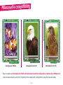
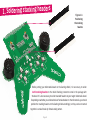
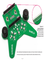
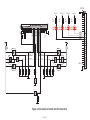
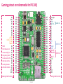
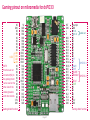
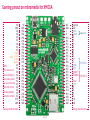
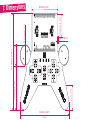
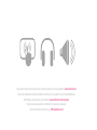
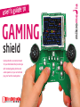
to
GAMING
shield
Gaming shield is an extension board
for your mikromedia that provides you
with standard gaming buttons and
audio speakers, so you can build and
play your favorite arcade games.
mikrome ia
user's guide
TO OUR VALUED CUSTOMERS
I want to express my thanks to you for being interested in our products and for having
confidence in Mikroelektronika.
The primary aim of our company is to design and produce high quality electronic products
and to constantly improve the performance thereof in order to better suit your needs.
Nebojsa Matic
General Manager
The Microchip, Atmel, NXP and CYPRESS name, logo and products names are trademarks of Microchip, Atmel, NXP and CYPRESS Inc. in the U.S.A and other countries.
Table of Contents
Introduction to mikromedia GAMING shield
4
Mikromedia compatibility
5
Key Features
6
System Specification
7
1. Soldering stacking headers
8
2. Connecting to mikromedias
10
3. Connecting to other shields
11
4. Control Buttons and signal LEDs
12
5. Audio module
14
6. Gaming pinout on supported mikromedia boards
16
Gaming pinout on mikromedia for PIC18FJ
16
Gaming pinout on mikromedia for dsPIC33
17
Gaming pinouton mikromedia for XMEGA
18
7. Dimensions
Page 3
19
ING
Introduction to mikromedia GAM
mikromedia GAMING shield is an extension
board pin-compatible with several mikromedia
boards from mikroElektronika that enables
users to provide button controls and audio
interface to your base mikromedia board,
which is specially suitable for creating your
own gaming console. GAMING Shield comes
with convenient stacking connectors, so you
can easily connect not only mikromedia, but
other shields as well, such as Battery boost
shield. It’s carefully designed to fit perfectly
into anyone’s hands, and it has convenient
holders which provide great stability when
board is connected to mikromedia.
Page 4
shield
Mikromedia compatibility
mikromedia for XMEGA
mikromedia for dsPIC33
mikromedia for PIC18FJ
Board is compatible with mikromedia for PIC18FJ v105, mikromedia for dsPIC33 v105 & v106 and mikromedia for XMEGA v110.
All of the mentioned boards can exploit the full potential of the Gaming Shield, including buttons, signal LEDs and audio speakers.
Page 5
Key Features
01
01 Top connections pads
03
02
02 Left Audio Channel amplifier circuit
03 Right Audio Channel amplifier circuit
04 Bottom connections pads
06
04
05 Left Speaker
06 Right Speaker
11
05
07 Navigation Joystick
08 Action Joystick
09 Reset Button
09
08
07
10
10 Start Button
11 Indicator LEDs
12 Left hand grip
13 Right hand grip
12
Page 6
13
System Specification
power supply
Over a USB cable (5V DC)
power consumption
50mA in idle state
(when on-board modules are off)
board dimensions
15.2 x 15.1cm (5.98’’ x 5.94’’)
weight
~74g (0.16 lbs)
Page 7
1. Soldering stacking headers
Figure 1-1:
Positioning
the stacking
headers
Before putting your mikromedia board on the Gaming shield, it is neccessary to solder
1x26 stacking headers to the shield. Stacking connectors come in the package with
the board. It is also necessary to solder standard headers to your target mikromedia board.
Depending on whether you soldered male or female headers to the mikromedia, you should
position the stacking headers on the Gaming shield accordingly, so they can be connected
together in a male-female (or female-male) pattern.
Page 8
Figure 1-2:
Correctly soldered
stacking connectors
on the back side
with just enough
soldering wire used
When soldering the stacking headers, make sure not to put too much soldering wire
on the pins, because you won’t be able to stack the desired shields correctly.
Page 9
2. Connecting to mikromedias
Once you have soldered the stacking headers, you can
connect your mikromedia to the gaming shield. Make sure
to connect the boards so that the shapes of mikromedia
and top of the gaming shields are aligned.
Figure 2-1: mikromedia
board correctly placed on
the gaming shield
Page 10
3. Connecting to other shields
When front side is connected with mikromedia, the
rear side of the board can be used for stacking other
mikromedia shields, such as the Battery Boost shield.
Make sure to solder the appropriate headers to this addon shield, and make sure to match the board outlines
when connecting them together.
Figure 3-1: Battery
Boost shield correctly
placed on the gaming shield
Page 11
4. Control Buttons
and signal LEDs
mikromedia Gaming shield provides standard
button controls required in most arcade games.
There are two sections of buttons for standard
gaming functions: steering (left,
right, up, down), actions
(triangle, square, x, and
circle), but we also added
Start and Reset buttons.
Board features four signal
LEDs which can be used as
indicators of game status,
or other activities.
Figure 4-1: Buttons
and indicator LEDs are
convenient for gameplay
Page 12
VCC-5V
VCC-3.3
VCC-3.3
R3
4K7
R2
4K7
R1
4K7
R0
4K7
LD3
RED
LD2
RED
LD1
RED
LD0
RED
LED-0
LED-1
LED-2
LED-3
T1
T3
VCC-3.3
VCC-3.3
L
R
JOY1-L
JOY1-U
JOY1-D
JOY1-R
JOY2-L
JOY2-U
JOY2-D
JOY2-R
START
RST
S1X26
VCC-3.3
T5
T2
JOY1-U
JOY2-U
JOY1-L
JOY2-R
JOY1-R
JOY2-L
JOY1-D
JOY2-D
T6
T8
T4
T7
R16
100K
R15
100K
R14
100K
R13
100K
R17
100K
R9
100K
R18
100K
R19
100K
R20
100K
T9
T10
START
R21
100K
Figure 4-2: Schematics of button and LED connections
Page 13
VCC-3.3
S1X26
5. Audio module
Figure 5-1:
LM4864 audio
amplifier circuit
Board is equipped with two
LM4864 300mW audio power
amplifiers, which are connected one
to each speakers, thus making a stereo
audio system. Left and right audio signals are
brought to the board directly from the mikromedia
board via two connections pins.
Page 14
U2
C1
100nF
E1
10uF
R8
LEFT
20K
C2
100nF
SHUTDOWN
VO2
BYPASS
GND
+IN
VDD
-IN
VO1
SP1+
SP1
+
VCC-3.3
C5
VCC-3.3
SP1-
-
100nF
EMB3008A
LM4864
R6
75K
U3
C3
100nF
E2
10uF
R5
RIGHT
20K
C4
100nF
SHUTDOWN
VO2
BYPASS
GND
+IN
VDD
-IN
VO1
SP2+
SP2
+
C6
VCC-3.3
SP2-
EMB3008A
LM4864
R7
75K
Figure 5-2: Left and right audio amplifier circuit schematics
Page 15
VCC-3.3
100nF
Gaming pinout on mikromedia for PIC18FJ
NC
GND
NC
NC
NC
NC
NC
NC
NC
LD0
LD1
LEDS
LD2
LD3
NC
NOTE:
NC
Pins that are not
NC
connected (NC) to NC
the gaming shield NC
NC
can be used on the NC
NC
other side of the
stacking headers NC
NC
with other shields NC
3.3V
GND
5V
GND
RA2
RA3
RA5
RF2
RF5
RF6
RH4
RB0
RB1
RB2
RB3
RJ0
RJ1
RJ2
RJ3
RJ4
RJ5
RC0
RA4
RC3
RC4
RC5
3.3V
GND
RST
GND
L
R
RC2
RE6
RE5
RB4
RC1
RE2
RE1
RE0
RG0
RE4
RE3
RE7
RB6
RB7
RG2
RG1
RC7
RC6
RD6
RD5
3.3V
GND
Gaming shield functions
Reset pin
GND
left ch.
audio out
right ch.
NC
NC
NC
NC
NC
NC
NC
LEFT
UP
JOYSTICK 1
DOWN
RIGHT
SQUARE
TRIANGLE JOYSTICK 2
X
CIRCLE
START
NC
NC
NC
NC
3.3V
GND
Gaming shield function
Page 16
Gaming pinout on mikromedia for dsPIC33
NC
GND
NC
NC
NC
NC
NC
NC
NC
LD0
LD1
LEDS
LD2
LD3
NC
NOTE:
NC
Pins that are not
NC
connected (NC) to NC
the gaming shield NC
NC
can be used on the NC
NC
other side of the
NC
stacking headers
NC
with other shields NC
3.3V
GND
5V
GND
RB1
RB2
RB3
RB4
RB5
RB8
RB9
RA12
RA13
RA14
RA15
RA2
RA3
RF6
RF7
RF8
RG15
RA1
RA0
RG6
RG7
RG8
3.3V
GND
RST
GND
L
R
RD0
RD1
RD2
RD3
RD4
RD5
RD8
RD9
RD14
RD15
RD6
RD7
RA9
RA10
RF0
RF1
RF2
RF3
RG2
RG3
3.3V
GND
Gaming shield functions
Reset pin
GND
left ch.
audio out
right ch.
NC
NC
NC
NC
NC
NC
NC
LEFT
UP
JOYSTICK 1
DOWN
RIGHT
SQUARE
TRIANGLE JOYSTICK 2
X
CIRCLE
START
NC
NC
NC
NC
3.3V
GND
Gaming shield function
Page 17
Gaming pinout on mikromedia for XMEGA
NC
GND
NC
NC
NC
NC
NC
NC
NC
LD0
LD1
LEDS
LD2
LD3
NC
NOTE:
NC
Pins that are not
NC
connected (NC) to NC
the gaming shield NC
NC
can be used on the NC
NC
other side of the
NC
stacking headers
NC
with other shields NC
3.3V
GND
5V
GND
PB1
PB2
PB3
PA4
PA5
PA6
PA7
PH0
PH1
PH2
PH3
PE1
PE0
PC7
PC6
PC5
PH7
PC4
PD4
PD7
PD6
PD5
3.3V
GND
RST
GND
L
R
PC0
PC1
PC2
PC3
PF0
PF1
PE4
PJ7
PR0
PR1
PE2
PE3
PE6
PE7
PF6
PF7
PD2
PG3
PD1
PD0
3.3V
GND
Gaming shield functions
Reset pin
GND
left ch.
audio out
right ch.
NC
NC
NC
NC
NC
NC
NC
LEFT
UP
JOYSTICK 1
DOWN
RIGHT
SQUARE
TRIANGLE JOYSTICK 2
X
CIRCLE
START
NC
NC
NC
NC
3.3V
GND
Gaming shield function
Page 18
37.9 mm (1.50")
69.00 mm (2.72")
33.00 mm (1.30")
151.00 mm (5.95")
36.00 mm (1.42")
31.00 mm (1.22")
7. Dimensions
80.90 mm (3.19")
3.00mm (0.12”)
152.00 mm (6.00")
Page 19
Notes:
Page 20
Notes:
Page 21
Notes:
Page 22
DISCLAIMER
All the products owned by MikroElektronika are protected by copyright law and international copyright treaty. Therefore, this manual is to be treated as any
other copyright material. No part of this manual, including product and software described herein, may be reproduced, stored in a retrieval system, translated or
transmitted in any form or by any means, without the prior written permission of MikroElektronika. The manual PDF edition can be printed for private or local
use, but not for distribution. Any modification of this manual is prohibited.
MikroElektronika provides this manual ‘as is’ without warranty of any kind, either expressed or implied, including, but not limited to, the implied warranties or
conditions of merchantability or fitness for a particular purpose.
MikroElektronika shall assume no responsibility or liability for any errors, omissions and inaccuracies that may appear in this manual. In no event shall MikroElektronika, its directors, officers, employees or distributors be liable for any indirect, specific, incidental or consequential damages (including damages for
loss of business profits and business information, business interruption or any other pecuniary loss) arising out of the use of this manual or product, even if
MikroElektronika has been advised of the possibility of such damages. MikroElektronika reserves the right to change information contained in this manual at
any time without prior notice, if necessary.
HIGH RISK ACTIVITIES
The products of MikroElektronika are not fault – tolerant nor designed, manufactured or intended for use or resale as on – line control equipment in hazardous
environments requiring fail – safe performance, such as in the operation of nuclear facilities, aircraft navigation or communication systems, air traffic control, direct life support machines or weapons systems in which the failure of Software could lead directly to death, personal injury or severe physical or environmental
damage (‘High Risk Activities’). MikroElektronika and its suppliers specifically disclaim any expressed or implied warranty of fitness for High Risk Activities.
TRADEMARKS
The Mikroelektronika name and logo, the Mikroelektronika logo, mikroC, mikroC PRO, mikroBasic, mikroBasic PRO, mikroPascal, mikroPascal PRO, AVRflash,
PICflash, dsPICprog, 18FJprog, PSOCprog, AVRprog, 8051prog, ARMflash, EasyPIC5, EasyPIC6, BigPIC5, BigPIC6, dsPIC PRO4, Easy8051B, EasyARM, EasyAVR5,
EasyAVR6, BigAVR2, EasydsPIC4A, EasyPSoC4, EasyVR Stamp LV18FJ, LV24-33A, LV32MX, PIC32MX4 MultiMedia Board, PICPLC16, PICPLC8 PICPLC4,
SmartGSM/GPRS, UNI-DS are trademarks of Mikroelektronika. All other trademarks mentioned herein are property of their respective companies.
All other product and corporate names appearing in this manual may or may not be registered trademarks or copyrights of their respective companies, and are
only used for identification or explanation and to the owners’ benefit, with no intent to infringe.
© Mikroelektronika™, 2011, All Rights Reserved.
If you want to learn more about our products, please visit our website at www.mikroe.com
If you are experiencing some problems with any of our products or just need additional
information, please place your ticket at www.mikroe.com/en/support
If you have any questions, comments or business proposals,
do not hesitate to contact us at [email protected]