1
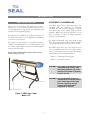
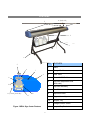
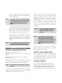
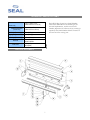
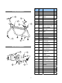
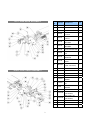
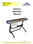
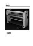
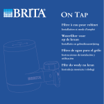
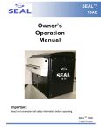
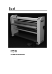
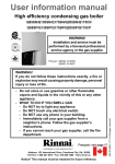
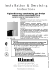
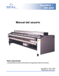
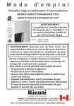
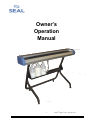
Owner’s Operation Manual 1 SEAL Sign Coater – Model 1371 INTRODUCTION STATEMENT OF INTENDED USE SEAL SIGN COATER The SEAL Sign Coater is ETL approved to UL standards and CE approved to European standards. The unit has been designed to be used with SEAL Sign Coater Liquid made by SEAL Graphics. When used with this product, you are able to laminate a variety of flexible substrates from 5 to 14 mil thickness Thank you for purchasing the SEAL Sign Coater Model 1371. As you become familiar with the coater, you will appreciate its high quality of workmanship and excellence in its engineering design. By following the guidelines for proper care and use of the SEAL Sign Coater you can depend on maximizing your return on investment. We highly recommend using only SEAL Liquid Clear Coat and Cleaner made by SEAL Graphics for maximum performance from your new coater. The purpose of this manual is to describe installation, operation and maintenance of your SEAL Sign Coater to enhance signs, displays, and other flexible graphics with professional results. The SEAL Sign Coater uses a two-step process to coat the graphics and clean the system without having to manually scrub the Meyer Bar Roller. This includes the coater liquid and water. Please read and fully understand the entire manual before using your coater. STEP 1 -- SEAL Sign Coater Liquid STEP 2 -- Neutralizer (water) WARNING: This coater is designed for single sided laminating. Use for other than these purposes may cause damage to the coater or physical harm to the user. WARNING: Any unauthorized changes or modifications to this unit without prior written approval will void the user’s warranty and will transfer health and safety obligations to the user. Figure 1: SEAL Sign Coater Model 1371 1 LIABILITY STATEMENT CAUTION: Pay attention to all passages marked this way. This information is vital to preventing user injury and/or damage to the unit. Failure to follow this information could void the user’s warranties and transfer all safety obligations to the user. Details provided in this manual are based on the most current information available. However, these details may be subject to change at any time. SEAL Graphics retains the right to make changes to the construction or design of our products without accepting any responsibility for modifying earlier versions previously delivered. WORKSPACE & INSTALLATION WORKSPACE Place the unit in a well lit, dust free area with plenty of room for laying out wet prints. The coater must be level. Make sure to place the coater in an area with adequate ventilation. Do not place the unit near open flames. Depending on size of the images being coated, drying racks may be appropriate, there are after market racks available. Two examples are Dick Blick Art Materials – www.dickblick.com and Saturn Rack Company – www.saturnrack.com. SETTING UP Space should be available so that there is sufficient feedin/out area, as well as space in which to place tables for drying and trimming. ELECTRICAL REQUIREMENTS Assemble the stand. Place the SEAL Sign Coater over the matching holes in the leg support brackets. Fasten the coater to the brackets using screws and washers provided. Fasten the storage shelf to the stand. Follow power installation set up Instructions below before connecting the supply power. UNPACKING The SEAL Sign Coater is shipped in two containers. The largest container holds the coating unit, a bag of hardware, and this manual. The smaller container holds the stand assembly, assembly instructions, the casters, and a bag of hardware. It is recommended that you assemble the stand first. Check voltage selector switch position before connecting the supply power. The voltage selector switch is located above the power inlet. Use a straight blade screwdriver to slide voltage selector switch all the way right or left to match the supply power. The correct supply voltage should be visible. Failure to have the voltage selector switch in the correct position could result in poor performance or unit damage. CAUTION: We recommend that the coater be connected to an electrical circuit with a Ground Fault Interrupter (GFI) circuit breaker. 2 SAFETY The SEAL Sign Coater is designed to use water-based lacquer only. Use of solvent based or other manufacturer’s lacquers may damage the machine and void the machines warranty. SAFETY COVERS The two end safety covers (blue) protect the user from the mechanism used to power the roller assembly. Only qualified maintenance or safety personnel should remove the covers for maintenance upkeep or repair. WARNING: Whenever using any equipment, always follow manufacturers’ instructions to ensure safe operation. DANGER: FOR ANY SERVICING, ALWAYS UNPLUG THE UNIT BEFORE REMOVING SAFETY COVERS. Become familiar with all operational controls and ensure that all pre-start settings have been established. Comply with all safety warning signs, labels and instructions. SAFETY SYMBOLS Ensure that prior to clean-up, eye protection, clean towels, rubber gloves and ventilation devices (such as fans) are available where appropriate. ROTATING PARTS: RISK OF INJURY Whenever filling or emptying the lacquer tray, eye protection should be worn. Ensure that an approved eyewash station is adjacent to the coater. WARNING: Hazardous moving parts. Keep fingers and other body parts away. Avoid contact with uncured lacquer. In case of skin contact, use soap and water to clean the skin. ELECTRICAL PARTS: DANGER OF BEING INJURED BY DANGER: Do not use solvents to remove lacquer from the skin. Solvents can cause lacquer to penetrate the skin. ELECTRICITY DANGER: CAUTION: Prior to handling any chemical product, read the product label for safe handling information. Also review MSDS sheets prior to chemical use to gain a complete understanding of health, safety and environmental information. Observe manufacturers recommendations when handling chemicals. DO NOT ATTEMPT Access TO this area because of the risk of injury by high voltage. Only authorized maintenance OR service technicians SHOULD ATTEMPT repair OF this AREA. PREVENTIVE MEASURES Be careful not to feed objects such as staples, paper clips and rough or abrasive materials into the nip opening. Keep objects such as tools, rulers, pens, markers or knives clear of the nip opening. To obtain MSDS Sheets for any SEAL products, contact SEAL Technical Services at (800) 486-6502 (USA) or +31 572 345 500 (Europe). DO NOT leave these items on the table to avoid accidentally feeding them into the machine. 3 FEATURES 11 (back side) 5 4 3 2 1 5 6 7 4 8 9 11 (control panel side) 12 10 Figure 2 SEAL Sign Coater Features 4 NO. FEATURES 1 Stand 2 Storage Shelf 3 Drain Valve 4 Power On/Off Switch 5 Nip Roller Adjustment Knob (both ends) 6 Nip Roller Assembly 7 Feed Table 8 Meyer Bar Roller 9 Stripper Assembly 10 Lacquer Tray 11 Voltage Selector Switch 12 Lacquer Tray Bracket CONTROLS AND OPERATION OPERATION POWER ON/OFF The function of the Power On/Off switch is to enable the coater for operations. MATERIALS NEEDED Prior to operation, make certain the following materials are available: NIP ROLLER ADJUSTMENT KNOBS The two Nip Roller Adjustment Knobs control the gap between the Meyer Bar Roller and the Nip Rollers. The gap can be adjusted from a maximum of .06" (clockwise, until tight) to a minimum of .04" by turning both knobs counterclockwise ¾ of a turn. The chart below reflects typical settings. The setting position of 1 is a .06" gap (fully tightened). Settings 2-4 are alternate adjustment positions, set by turning the knobs counterclockwise, up to a ¾ revolution from the tightened position. • Face shield or safety glasses • Absorbent towels – clean, lint-free and disposable. • Rubber gloves PRE-START CHECKS Plug the coater into a standard outlet (see page 7 for model voltage requirements) and turn the coater ON to start the rollers turning. NOTE: Any additional rotation of the knobs counterclockwise beyond ¾ of a turn has no affect. Remove stripper assemblies and fill the lacquer tray, being sure not to exceed the lines labeled “Do Not Fill Above” located inside the tray. NOTE: The lacquer will evaporate over time. Have plenty of lacquer available at all times. SUGGESTED NIP SETTINGS MEDIA SETTING Banner Vinyl – 8oz 4 Banner Vinyl – 12oz Banner Vinyl – 16oz 3 2 Banner Vinyl – 20oz 1 Cast PSV 3 Calandared PSV Canvas 250 gram 2 3 Canvas 310 gram 2 Allow sufficient time (a few minutes) before starting operations to ensure the Meyer Bar Roller gets evenly coated with lacquer. There will be a visible white film over the entire width of the Roller when coated. Once the Meyer Bar Roller is thoroughly coated apply the stripper assemblies. You may begin operations. DANGER: 4 Wet Strength Paper The settings are suggested only. Final setting may be different according to materials used and manufacturing tolerances. Seal suggests logging a reference table according to materials you used. Do not operate the coater with the roller cover open. PROCESSING IMAGES It is important to “batch” your jobs and run them one after the other. 1. Place the image face down and feed it into the nip roller assembly with a smooth and consistent approach at a right angle with the rollers. TIP: if possible leave a 1 in. border around the image to be coated to prevent a build up of lacquer on the edge of the image. Nip Gap Adjustment Knob (see figure 2) 5 2. As the image is fed beneath the nip rollers, lacquer is applied from the Meyer Bar Roller to the face of the image. NOTE: Next, close the drain valve and fill the tray reservoir with water (we recommend filling an empty one gallon jug with normal tap water to facilitate this process). Let the water “work” to neutralize the cleaner for approx. 10 minutes before draining. You can now switch off the power and blot the transfer roller with a dry, clean cloth. The tray may be removed to facilitate this process, and the tray may be rinsed in a utility sink if available. The image may not propel itself through the coater on its own. You may need to assist the print through the coater by pulling on the image as it exits the coater. 3. As the image exits the rollers, grab the top edge on each side and pull up over the coater in a smooth and even motion, being careful not to drip coating on the coater itself. Larger images may require someone on the exit side of the coater pulling up and away from the coater. CAUTION: Be sure to transfer the drain tube from the coating bottle to the water bottle before draining cleaner. 4. Turn the image over, coated side up and lay flat on a drying table. TIP: using an oversized soft substrate to lay the print on and tacking the edges down can eliminate uneven coating of the edges. NOTE: NOTE: The coating should be dry to the touch in 15 to 30 minutes, but may not be fully cured for up to an additional 24 hours. The final step is to use a clean cloth and rubbing alcohol to wipe down the roller to get any last lacquer that may be remaining. CLEANING THE COATER GENERAL CLEANING INSTRUCTIONS Do not use spray-on cleaners. Do not immerse any part of the coater in water or other liquids. Do not use an abrasive cleaner, which can damage painted surfaces. Do not allow water or other liquids to enter the electrical circuits, this may cause personal injury and/or damage to the equipment when power is applied. NOTE: If you blot the roller while still turning, be sure not to allow any loose ends of the cloth to wrap around the roller. Should this occur, immediately switch off the power and carefully pull to remove the cloth. SERVICE & REPLACEMENT PARTS Service and maintenance must be performed fully in accordance with the instructions. Servicing by any unauthorized technician voids the warranty. Service Technician must use replacement parts as specified by SEAL Graphics. TECHNICAL SERVICE For technical assistance, please contact SEAL Technical Service Department. (See rear cover.) When calling for technical service please have the Coater serial number available (located on the identification plate on the bottom of main housing) Leave machine on during the cleaning process. After you are finished laminating prints for the day, simply place the drain tube back into the original bottle of liquid coating and open the drain valve. 6 TECHNICAL SPECIFICATIONS Dimensions Each SEAL Sign Coater has a Serial Number Label. This label indicates the model type, the electrical requirements, and the coater serial number (important for reference if any servicing is required). The Serial Number Label is located on the bottom of the coating unit. 65 in. x 11 5/8 in. x 6 in. (1.65 M x 29.5 cm x 15.25 cm) (Coater only) Shipping Dimensions (Coater only) 73 in. x 14 in. x 15 in. (1.85 M x 35.5 cm x 38 cm) Net Weight (Coater only) 75 lbs. (165 kg) Shipping Weight 80 lbs. (176 kg) Nip Settings (Coater only) 0.020 in. (0.5 mm) Electrical Order Code 115 VAC/1A/60Hz 230VAC/1A/50Hz 63155 (115V) R R O 63156 (230V) ROLLER ASSEMBLY 7 STAND ASSEMBLY 19 18 17 22 16 21 20 ITEM NO. PART NO. 1 2 DESCRIPTION QTY 7000235 LACQUER TRAY 1 7000255 STRIPPER ASSEMBLY 4 3 7000101 TABLE FEED-IN EXT 1 4 7000151 MEYER BAR ROLLER WIRE WRAP 1 5 7000110 ROLL NIP 2 6 7000103 TOP LID EXTRUSION 1 7 7000102 FRONT BAR EXTRUSION 1 8 7000122 RAIL EXTRUDED 1 9 7000179 10 7000205 11 7000208 PLATE ASSEMBLY RIGHT SIDE 1 12 7000243 THREADED ROD 1 13 89000137 3/16 FENDER WASHER 3 14 A405100 10-32 NUT 1 15 7000244 DISC SPRING 2 16 7000210 17 7000139 18 7000191 19 7000192 20 7000193 21 7000196 22 7000198 23 7000209 24 7000175 MOTOR, DUAL VOLTAGE 1 25 7000143 PLATE MOUNTING MOTOR 1 26 7000121 GEAR 18T SPUR 2 27 A410101 #10 LOCK WASHER 8 MOTOR ASSEMBLY 24 27 26 25 23 8 HOSE ASSEMBLY W/BALL VALVE & CLAMP PLATE ASSEMBLY LEFT SIDE 1/4-20 KEPS NUT BLACK ZINC SHELF STAND LEG WELDMENT RIGHT HAND SIDE LEG WELDMENT LEFT HAND SIDE LEG WELDMENT STAND FRONT CASTER TWIN WHEEL SWIVEL 1/4-20 X 2.5" BHC BLACK ZINC SCREW, THREAD FRMNG 10-32X3/4" 1 1 2 1 1 1 1 4 2 18 28 7000242 LATCH 1 29 A410100 #10 FLAT WASHER 1 30 A405110 #10-32 NYLOCK NUT 1 LEFT SIDE GEAR ASSEMBLY RIGHT SIDE GEAR ASSEMBLY 9 ITEM NO. PART NO. DESCRIPTION QTY 31 7000239 TRAY BRACKET 2 32 7000202 SHIELD MOTOR 1 33 7000105 ARM, ADJUSTMENT 2 34 7000203 BEARING, BALL 3/8 ID X 7/8" OD 4 35 7000107 BUSHING, FLANGED 0.250" ID 2 36 7000158 RING EXTERNAL RETAINING 2 37 7000149 RING EXTERNAL RETAINING 2 38 7000104 STOP ADJUSTING ARM 2 39 7000204 BEARING, 1.0" ID X 2.0" OD 2 40 7000182 SWITCH, VOLTAGE SELECTOR 1 41 7000183 CONNECTOR, POWER ENTRY 1 42 88700509 43 7000161 1/4-20 X 5/8" PHMS 4 44 7000111 GEAR 24T 2 45 7000112 GEAR 50T 1 46 7000155 SCREW 4 X 3/8" 8 47 7000109 BUMPER RECESSED RUBBER 4 48 7000108 KNOB ADJUSTMENT SS 2 49 79036 1/4" SAE FLAT WASHER 2 50 7000162 GROUND SCREW 1 51 7000129B 52 7000126B FUSE HOLDER (FUSE - PN 7000164) END COVER - RHS (NOT SHOWN) END COVER - LHS (NOT SHOWN) 1 1 1 53 A410103 1/4" LOCK WASHER 4 54 A405112 #10-32 HEX NUT 4 55 A430183 #10-32 X 1.25” BOLT 4 LIMITED WARRANTY SEAL Graphics warrants to the original consumer purchaser that each new SEAL Sign Coater made by SEAL. which proves defective in materials or workmanship within the applicable warranty period, will be repaired or, at our option, replaced without charge. Effective November 1st, 2002 the applicable warranty period for New Equipment shall be one year (parts) from date of purchase. This warranty extends to and is enforceable only by the original consumer purchaser, and only for the period (during the applicable term), which the product remains in the possession of the original consumer purchaser. "Original consumer purchaser" means the person who first purchased the product covered by this warranty other than for purpose of resale. This warranty does not apply if it is found that at any time the equipment has not been used for its intended purpose. For more information regarding this warranty, please contact your distributor. WARNING: Changes or modifications to this unit not expressly approved by the party responsible for compliance could void the user's authority to operate the equipment The information contained in this document is subject to change without notice and should not be construed as a commitment by SEAL Graphics. SEAL Graphics assumes no responsibility for any errors that may appear in this document. Nor does it make expressed or implied warranty of any kind with regard to this material, including, but not limited to, the implied warranties of merchantability and fitness for a particular purpose. SEAL Graphics shall not be liable for incidental or consequential damages in connection with, or arising out of the furnishing, performance, or use of this document and the program material, which it describes. Trademarks Credits SEAL® is a registered trademark of SEAL Graphics. ©Copyright SEAL® Graphics 2005 WARNING: Any unauthorized changes or modifications to this unit without the prior written approval of SEAL will void the user’s warranty and will transfer health and safety obligations to the user. All rights are reserved. No part of the document may be photocopied, reproduced, or translated without the prior written consent of SEAL Graphics. 10 SEALSign Coater Model 1371 SEAL Technical Service SEAL Technical Service – Europe and Asia Pacific (For technical assistance & service) (For technical assistance & service) Tel: 1-800-486-6502 For UK: Tel: +31 572 345 500 Fax: 1-800-966-4554 Fax: +31 572 345 501 For NL: Tel: +31 572 345 500 Fax: +31 572 345 501 SEAL Customer Service SEAL Customer Service – Europe and Asia Pacific (For information and placing orders) (For information and placing orders) Tel: 1-800-257-7325 Tel: +31 572 345 500 Fax: 1-800-966-4554 Fax: +31 572 345 501 Note: SEAL Graphics recommends that a licensed electrician in accordance with electrical codes in your area install your main power. Seal Graphics Americas Corporation 7091 Troy Hill Drive Elkridge, MD 21075 Tel: 410-379-5400 Fax: 410-579-8960 Seal Graphics Canada 1601 Matheson Blvd. E. Unit #4 Mississauga, Ontario Canada, L4W 1H9 Tel: 905-212-9232 Fax: 905-212-9313 Seal Graphics U.K. Ltd 1, Watkins Close Burnt Mills Industrial Estate Basildon, Essex SS13 1TL United Kingdom Tel: +44 1268 722 400 Fax: +44 1268 725 864 www.sealgraphics.com © 2005 SEAL Graphics SEAL and Image are registered trademarks of SEAL Graphics Part # OMSSC-E Rev. C (05/05) Seal Graphics Europe BV Kanaaldijk O.Z.3 P.O. Box 29, 8100 AA Raalte The Netherlands Tel: +31 572 345 500 Fax: +31 572 345 501 Seal Graphics Pacific Limited Unit A, 13th Floor, Block 1 Leader Industrial Centre Tsuen Wan, New Territories, Hong Kong Tel: +852 2407 3738 Fax: +852 2408 0973