1
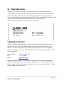
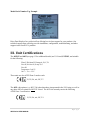
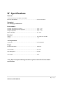
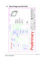
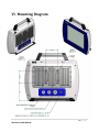
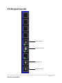
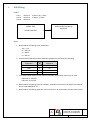
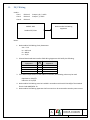
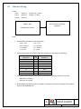
4023 Series
User Manual
May 15, 2013
DISCLAIMER
Daisy Data Displays, Inc. makes no representations or warranties with respect to the contents or
use of this manual, and specifically disclaims any express or implied warranties of
merchantability or fitness for any particular purpose. Daisy Data Displays, Inc. reserves the right
to revise this publication and to make changes to its content, at any time, without obligation to
notify any person or entity of such revisions or changes.
Furthermore, Daisy Data Displays, Inc. makes no representations or warranties with respect to
any Daisy Data Displays manufactured equipment, and specifically disclaims any express or
implied warranties of merchantability or fitness for any particular purpose. Daisy Data Displays,
Inc. reserves the right to make changes to any and all Daisy Data Displays manufactured
equipment, at any time, without obligation to notify any person or entity of such changes.
FCC WARNING
Computing devices and peripherals manufactured by Daisy Data Displays generate, use, and can
radiate radio frequency energy, and if not installed and used in accordance with the instructions
in this manual may cause interference to radio communications. Such equipment has been tested
and found to comply with the limits for a Class A computing device pursuant to Subpart J of Part
15 of the FCC Rules, which are designed to provide reasonable protection against radio
interference when operated in a commercial environment. Operation of this equipment in a
residential area is likely to cause interference, in which case the user - at his own expense - will
be required to take whatever measures may be required to correct the interference.
Some components may not have been manufactured by Daisy Data Displays, Inc. If not, Daisy
has been advised by the manufacturer of the component that the component has been tested and
complies with the Class A computing device limits as described above.
Daisy Data Displays, Inc.
2850 Lewisberry Road
York Haven, PA 17370 USA
Phone: (717) 932-9999
Fax: (717) 932-9000
www.d3inc.net
May 2013
Manual Revision 3.0
Copyright ©2013, Daisy Data Displays, Inc. All rights reserved.
4023 Series USER MANUAL
2|Page
Limited Warranty and Liability Statement
To the original purchaser, Daisy Data Displays, Inc., hereinafter referred to collectively as
SELLER, warrants each of its manufactured products, and all components therein contained to
be free from defects in materials and/or workmanship for a period of 12 months from the date of
purchase.
Should a malfunction, or other indication of defect attributable directly to faulty materials and/or
workmanship occur, Seller will, at its option, and without charge to the customer for labor and
parts, repair or replace the defective product, F.O.B. Seller’s plant, but Seller will not be
responsible for freight from Purchaser to Seller’s plant. In no event shall Seller be liable for any
loss, inconvenience or damage, whether direct, incidental, consequential or otherwise resulting
from abuse, misapplication or modification of the product, improper or faulty power, damage
resulting from repairs or alterations performed by unauthorized persons, or conditions resulting
from any other equipment attached to the product.
Seller assumes no liability for damage occurring in transit due to the product not being returned
in its original shipping material.
This warranty is exclusive and is in lieu of any warranty of merchantability or fitness for a
particular purpose or other warranty of quality whether expressed or implied, except of
title and against patent infringement. Correction of nonconformities, in the manner and for
the period of time provided above, shall constitute fulfillment of all liabilities of the Seller to the
Purchaser with respect to, or arising out of the goods, whether based on contract, negligence,
strict tort or otherwise.
LIMITATION OF LIABILITY: The Seller shall not under any circumstances be liable
for special or consequential damages, such as, but not limited to, damage or loss of other
property or equipment, loss of profits or revenues, cost of capital, cost of purchased or
replacement goods, or claims of customers of Purchaser for service interruptions. The remedies
of the Purchaser set forth herein are exclusive, and the liability of Seller respect to any contract,
or anything done in connection therewith such as the performance or breach thereof, of from the
manufacture, sale, delivery, resale, installation or use of any goods covered by or furnished under
this contract whether arising out of contract, negligence, strict tort or breach of warranty or
otherwise, shall not, except as expressly provided herein, exceed the price of the goods upon
which such liability is based.
This warranty gives you specific legal rights, and you may also have other rights, which vary
from state to state. Seller makes every effort to provide clear and accurate technical information
on the application of its products in the Operator's Manual, and assumes no liability for misuse of
the information.
4023 Series USER MANUAL
3|Page
Table of Contents
DISCLAIMER .............................................................................................................................................. 2
FCC WARNING ........................................................................................................................................... 2
Limited Warranty and Liability Statement ................................................................................................... 3
I.
Revisions ............................................................................................................................................... 5
II.
Introduction .......................................................................................................................................... 6
III.
Unit Certifications ................................................................................................................................. 7
IV. Specifications ........................................................................................................................................ 8
V.
Block Diagram (4023CE)........................................................................................................................ 9
VI. Mounting Diagram .............................................................................................................................. 10
VII. Keypad Layout .................................................................................................................................... 11
VIII. Installation & Warnings ...................................................................................................................... 12
IX.
Parts List.............................................................................................................................................. 13
X.
Battery Storage & Operation .............................................................................................................. 15
XI.
Touch Screen Calibration .................................................................................................................... 15
4023 Series USER MANUAL
4|Page
I.
REV
1.0
2.0
3.0
Revisions
Description
Initial
Expanded to include other model, 4023AA;
Updated to include new ratings, UL Listing guidelines added
4023 Series USER MANUAL
Date
5/14/12
9/3/12
5/15/13
Author
RP
RP
RP
5|Page
II. Introduction
Thank you for selection a D3 solution for your hazardous area operator interface needs.
This manual reviews procedures for installing and operating D3 flat panel operator interface
systems. In addition to the setup instructions and diagrams in this manual, D3 provides an
overview of the methods used to ensure that electronic systems are safe for hazardous areas. This
explains the theory behind the unique product and services provided by D3.
Should you have any inquiries or concerns, please contact D3.
Customer Service
All Daisy systems pass detailed quality control configuration and inspection before being
shipped. D3 strives to create the highest quality systems, and chooses top quality parts.
However, like most electronic devices, units may experience issues over time. Should you
experience problems, or have any further inquiries or comments, please contact D3’s customer
service department:
Business Phone
Fax
Email
(717) 932-9999 x 222
(717) 932-8000
[email protected]
Equipment returned to D3 for service must be accompanied by a valid return merchandise
authorization (RMA) number. Items or products shipped to D3 without a valid RMA number
will be refused. An RMA will be generated upon receipt of Company Name, Address, Contact,
Product Model and Serial Numbers.
4023 Series USER MANUAL
6|Page
Model/Serial Number Tag Example
Daisy Data Displays Inc. prides itself on offering best in class support for your products. Our
technical support team can help you with installation, configuration, troubleshooting, and other
support issues for all D3’s products.
III. Unit Certifications
The 4023CE and 4023 (see page 13 for additional details) are UL Listed, E355015, and suitable
for the following:
Class I, Division II, Groups A, B, C, D
Class II, Division II, Groups F, G
Class III
Temperature Code T5
-20°C < Tamb < 55°C
These units are also ATEX Zone 2 rated as such:
II, 3G, Ex, nA, IIC, T5
The 4023 with options (e.g. 4023-796) other than those incorporated in the UL Listing, as well as
any other 4023xx variant are NOT UL Listed. The 4023AA currently carries the following
ATEX Zone 2 certification:
II, 3G, Ex, nA, IIC, T4
4023 Series USER MANUAL
7|Page
IV. Specifications
Materials
All materials comply with NEMA 4X standards
Enclosure and Hardware .......................................................................... 6061-T6 Aluminum
Mechanical
See drawings for dimensions
Environmental
Operating Temperature (No Heater) ........................................................ -20°C – 55°C
Operating Temperature (Heater Equipped) ............................................. -40°C - 65°C
Storage Temperature................................................................................ -20°C – 75°C
Relative Humidity.................................................................................... 5% - 95%
Electrical
Voltage .................................................................................................... 100- 240 VAC, 50/60 Hz
Current .................................................................................................... 1.8A
Air Requirements
Air Pressure ............................................................................................. No Air Required
Display
Resolution Maximum .............................................................................. 1280x768
Viewing Angle......................................................................................... 80° x 80°
Typical Brightness ................................................................................... 600 nits
Color Depth ............................................................................................. 24 bit
*Note: Due to frequent technological advances, please contact D3 for latest model
specifications.
4023 Series USER MANUAL
8|Page
V. Block Diagram (4023CE)
4023 Series USER MANUAL
9|Page
VI. Mounting Diagram
4023 Series USER MANUAL
10 | P a g e
VII. Keypad Layout
Power Indicator
Hard Disk Indicator
Brightness Up
Brightness Down
4023 Series USER MANUAL
11 | P a g e
VIII.
Installation & Warnings
WARNING: EXPLOSION HAZARD – DO NOT DISCONNECT EQUIPMENT WHILE THE
CIRCUIT IS LIVE OR UNLESS THE AREA IS KNOWN TO BE FREE OF IGNITABLE
CONCENTRATIONS.
WARNING: EXPLOSION HAZARD – SUBSTITUTION OF ANY COMPONENT MAY IMPAIR
SUITABILITY FOR CLASS I, DIVISION 2.
Unit and connections must be installed per Control Drawing No. D305-100009 (See page 16). For supply
connections, use wires suitable for at least 75°C.
Use Copper, Copper-Clad Aluminum, or Aluminum Conductors.
The 4023CE and 4023 are UL Listed with a Hoffman hole plug. End user is responsible for installation of
power input to unit. For proper use, all field wiring must be in compliance with applicable standards for
Class I, Division 2 classified areas or for ATEX Zone 2 areas, whichever may be applicable. Installation
must be done by a person familiar with the local regulations.
To Access Power Receptacle
1. Verify unit is in a nonhazardous area.
2. Unscrew the 10-32 button head screws around the gland plate and remove the plate to access
the Phoenix block.
3. Route cable through plate hole or hole plug (if equipped).
4. Connect power input to block and secure with contact screws.
5. Reposition the gland plate, reapply Loctite Blue 242 (if desired), and torque the 10-32 button
head screws to 10in-lb. using a calibrated torque-limiting screw driver.
4023 Series USER MANUAL
12 | P a g e
IX. Parts List
There are multiple variations of the 4023 throughout the series. While some parts (options) will allow
for increased functionality and more versatile usage, they may not yet have been certified for use
through an accredited testing laboratory, or have been certified for ATEX Zone 2 for suitability of usage.
Below are tables designating the main components for 4023 models.
Table 1 - 4023 - UL Listed/ATEX Zone 2 Certified
4023 – UL Listed, ATEX Zone 2 Certified
Part Description
Daisy Part Number
Motherboard – COM Express
P310-005000
Antennas
E907-000000
USB Controller Board
P310-008000
15” Capacitive Touch Screen
P040-000078
Touch Screen Controller
P040-100026
Nine Button Membrane
I302-000001
Membrane Controller
P310-009000
15” LCD Display
P000-000139
Optional Battery (Option 248)
E905-000017
RJ45 Connector & Cabling
I100-002099
USB Connector (x2) & Cabling
I100-002098
Power Supply
P010-000095
Table 1 presents the 4023 in its base configuration which has been sampled and listed by Underwriters
Laboratories, and is also ATEX Zone 2 certified as shown on page 7. This is a restricted configuration
which allows for only slight modification (gland plate location, option for rechargeable battery pack, and
alternate chipsets and memory options). User modifications will void the UL certification.
Table 2 - 4023CE - UL Listed/ATEX Zone 2 Certified
4023CE – UL Listed, ATEX Zone 2 Certified (UL Certified Options Added to 4023)
LEMO PS/2 Keyboard and Mouse (Option 788)
E203-200005 (Mouse), E203-200010 (Keyboard)
Table 2 presents the 4023CE, which is the base configuration of the 4023 from table 1, with the 788
option added for LEMO PS/2 connectors for keyboard and mouse connection. This option was included
in the scope of the UL certification. The unit is also ATEX Zone 2 certified as shown on page 7.
4023 Series USER MANUAL
13 | P a g e
Table 3 - 4023AA - ATEX Zone 2 Certified
4023AA – ATEX Zone 2 Certified ONLY (Non-UL Certified Options Added to 4023)
Motherboard – Axiomtek
P050-000274-01
15” LED Backlit LCD Display
P000-000129
Backlight Inverter
P005-000003
Power Supply
P010-000093
Table 3 presents the 4023AA. It is a modification of the base 4023, with a different motherboard, a 15”
LED backlight LCD display and inverter, and an alternate power supply. Due to these variations not being
included in the UL Certification project, this unit is only ATEX Zone 2 Certified, as shown on Page 7.
Future certification projects may incorporate these options.
Table 4 – Non-UL Certified Options
Additional 4023 Non-UL Certified Options to Add – ATEX Zone 2 Certified
Optional AC Heaters
Option 796
Optional DC Heaters
Option 899
Optional Thermostats – Paired with Option 796
Option 796
Resistive Touch Screen
Option 233
Table 4 presents additional options for the 4023 which are not UL certified. They are included in the
ATEX Zone 2 certification under a higher temperature class than the base configuration, as shown on
page 7. Future certification projects may incorporate these options.
4023 Series USER MANUAL
14 | P a g e
X. Battery Storage & Operation
The standard battery incorporated into the UL Listed 4023 is designed as a backup power source. In the
instance of a loss of primary power, the computer will run off of its Lithium-Ion battery. The battery
pack is a 14.4VDC, 6.6 Ah pack in a compact form factor. As such, it will only run the computer for up to
approximately one (1) hour. It can be used in short cycles solely on battery, however it is recommended
that the 4023 is used as a mounted, hardwired computer.
Charging: The battery charges when the unit is connected to its power source, and ends its charge cycle
when at full capacity. A full charge will take about three hours to charge.
Storage: Though the battery is embedded in a weather resistant enclosure and the 4023 storage
temperature is -20°C to +75°C, it is recommended that the battery not be subjected to long term
storage at a temperature outside -20°C to +60°C. For ideal battery life, the battery should be within 3050% capacity before placed into storage.
Life Expectancy: Under normal use and storage, the battery can be expected to deliver 80% or more of
its initial capacity after 300 charge cycles.
WARNING: BATTERY IS NOT TO BE REMOVED AND REPLACED BY USERS.
XI. Touch Screen Calibration
Each touch screen for the 4023 is calibrated and verified at D3 before the unit is shipped. Occasionally
settings may get altered and the 4023 will require recalibration. In order to do so, perform the following
simple procedure:
1. Locate the Microtouch application. Unless otherwise configured, a shortcut should be on
the desktop. Run the application.
2. Click the Calibrate button in the application.
3. Follow the onscreen instructions and perform the calibration.
4. Exit the application and the process is finished.
4023 Series USER MANUAL
15 | P a g e
ELECTRONIC MEDIA MAINTAINED. CHANGES SHALL BE INCORPORATED BY DESIGN ACTIVITY.
I) REVISIONS
DESCRIPTION
Initial
REV
-
DATE
June 28, 2013
APPROVED
RFR
PROPRIETARY INFORMATION OF
Daisy Data Displays, Inc
The information contained in this document is the confidential proprietary
property of Daisy Data Displays, Inc. REPRODUCTION or USE of this
information without the written consent of Daisy Data Displays, Inc is
STRICTLY PROHIBITED.
CONTROL DRAWING ALL SHEETS MAINTAINED AT THE SAME REVISION LEVEL
PART NUMBER(S):
4023
INITIAL APPROVAL
DATE
5/9/2013
Engineering Quality Control Administration Gregory Drapcho
Marty Etnoyer
May 9, 2013
Michael Hadaway
May 9, 2013
UNLESS OTHERWISE SPECIFIED:
DIMENSIONS ARE IN INCHES
DECMALS
FRACTIONS
2 PL±XX
±XXXX
FILE NAME: DOCUMENT1
May 9, 2013
Daisy Data Displays, Inc.
2850 Lewisberry Road
York Haven, PA 17370
717-932-9999
Model 4023 Nonincendive Field Wiring Control
Drawing D305-100009 SCALE: NONE
SHEET 1 of 5 I.
USB Wiring Used in: Class I Class II Class III Division 2 Division 2 Division 2 Groups A, B, C, and D Groups E, F, and G MODEL 4023 Standard USB Port Nonincendive Field Wiring Apparatus Notes: 1. Nonincendive Field Wiring Entity Parameters: Voc = 5.1 V Isc = 450 mA Ca = 999 µF La = 395 µH 2. Selected Associated Nonincendive Field Wiring Apparatus shall satisfy the following: Nonincendive Equipment Vmax Imax Ci + Ccable Li + Lcable ≥ ≥ ≤ ≤ Associated Apparatus Voc Isc Ca La 3. If the electrical parameters of the cable are unknown, the following values may be used: Capacitance = 60 pF/ft Inductive = 0.20 µH/ft 4. Nonincendive Field Wiring must be installed in accordance with article 501.10(B) of the National Electric Code ANSI/NFPA 70. 5. Nonincendive Field Wiring Apparatus shall not contain or be connected to another power source. SIZE
A
DOC NO
REV
-
D305-100009
SCALE: NONE
SHEET
2
II.
PS/2 Wiring Used in: Class I Class II Class III Division 2 Division 2 Division 2 Groups A, B, C, and D Groups E, F, and G MODEL 4023 Standard PS/2 Port Nonincendive Field Wiring Apparatus Notes: 1. Nonincendive Field Wiring Entity Parameters: Voc = 5.1 V Isc = 1063 mA Ca = 989 µF La = 70 µH 2. Selected Associated Nonincendive Field Wiring Apparatus shall satisfy the following: Nonincendive Equipment Vmax Imax Ci + Ccable Li + Lcable ≥ ≥ ≤ ≤ Associated Apparatus Voc Isc Ca La 3. If the electrical parameters of the cable are unknown, the following values may be used: Capacitance = 60 pF/ft Inductive = 0.20 µH/ft 4. Nonincendive Field Wiring must be installed in accordance with article 501.10(B) of the National Electric Code ANSI/NFPA 70. 5. Nonincendive Field Wiring Apparatus shall not contain or be connected to another power source. SIZE
A
DOC NO
REV
-
D305-100009
SCALE: NONE
SHEET
3
III.
Ethernet Wiring Used in: Class I Class II Class III Division 2 Division 2 Division 2 Groups A, B, C, and D Groups E, F, and G MODEL 4023 Standard Ethernet Port Nonincendive Field Wiring Apparatus Notes: 1. Nonincendive Field Wiring Entity Parameters: Vmax = 5.5 V Voc = 5.5 V Imax = 100 mA Isc = 100 mA Ci = 1000 pF Ca = 1000 µF Li = 0.5 µH La = 8 mH 2. Selected Associated Nonincendive Field Wiring Apparatus shall satisfy the following: Nonincendive Equipment Vmax Imax Ci + Ccable Li + Lcable Voc Isc Ca La ≥ ≥ ≤ ≤ ≤ ≤ ≥ ≥ Associated Apparatus Voc Isc Ca La Vmax Imax Ci + Ccable Li + Lcable 3. If the electrical parameters of the cable are unknown, the following values may be used: Capacitance = 60 pF/ft Inductive = 0.20 µH/ft 4. Nonincendive Field Wiring must be installed in accordance with article 501.10(B) of the National Electric Code ANSI/NFPA 70. SIZE
A
DOC NO
REV
-
D305-100009
SCALE: NONE
SHEET
4
IV.
Revision History REVISION ‐ CHANGE DESCRIPTION Initial DATE June 28, 2013 SIZE
A
AUTHOR
RFR DOC NO
REV
-
D305-100009
SCALE: NONE
SHEET
5


![[T3kCfg User Manual]](http://vs1.manualzilla.com/store/data/005811198_1-b56f11e7d0771a8aa23c614d4bbca2a5-150x150.png)