1
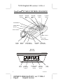
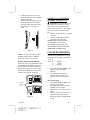
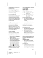
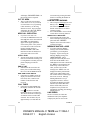
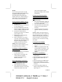
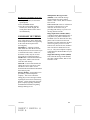
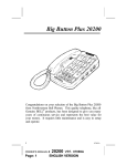
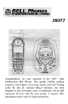
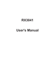
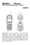
IMPORTANT SERVICE INFORMATION Read this manual before attempting to setup or use this instrument. It contains important information regarding safe installation and use. Keep this manual for future reference. Also save the carton, packing and proof of purchase to simplify and accelerate any needed action. If you need assistance or service, call (800) 888-8990 between 8:00 a.m. and 4:30 p.m. Pacific Standard Time, Monday through Friday. You can also visit our web site at http://www.nwbphones.com for technical support and information on our other products. WARNING To prevent fire or shock hazard, do not expose this product to rain or any type of excess moisture. If accidentally dropped into water, the AC adaptor should immediately be unplugged from the wall along with the telephone line cord. THIS SYMBOL IS INTENDED TO ALERT THE USER OF THE PRESENCE OF IMPORTANT OPERATING AND MAINTENANCE (SERVICING) INSTRUCTIONS IN THE OWNER'S MANUAL. ® EasyTouch II 76510 20 NUMBER MEMORY/CID/SPEAKERPHONE CARTON CONTENTS • Handset and Base Unit • Handset Cord • Long Telephone Line Cord • Short Telephone Line Cord • Wall Mount Bracket • User’s Manual • Warranty Card • Accessory Order Form 1 11159A-1 OWNER’S MANUAL#76510 ver.11159A-1 Page1 English Version 76510 English I/B version 11159A-1 SAVE THESE INSTRUCTION IMPORTANT SAFETY INSTRUCTIONS When using your telephone equipment, basic safety precautions should always be followed to reduce the risk of fire, electric shock, and injury to persons, including the following: 1. Read and understand all instructions. 2. Follow all warnings and instructions marked on the product. 3. Unplug this product from the wall outlet before cleaning. Do not use liquid cleaners or aerosol cleaners. Use a damp cloth for cleaning. 4. Do not use this product near water, for example, near a bathtub, washbowl, kitchen sink, or laundry tub, in a wet basement or near a swimming pool. 5. Do not place this product on an unstable cart, stand, or table. The product may fall, causing serious damage to the product. 6. Slots and opening in the cabinet and the back or bottom are provided for ventilation, to protect it from overheating. These openings should never be blocked or covered. The openings should never be blocked by placing the product on the bed, sofa, rug, or other similar surface. This product should never be placed near or over a radiator or heat register. This product should not be placed in a builtin installation unless proper ventilation is provided. 7. This product should be operated only from the type of power source indicated on the marking label. If you are not sure of the type of power supply to your home, consult your dealer or local power company. 8. Do not allow anything to rest on the power cord. Do not locate this product where the cord will be abused by persons walking on it. 9. Do not overload wall outlets and extension cords as this can result in the risk of fire or electric shock. 10. Never push objects of any kind into this product through cabinet slots as they may touch dangerous voltage points or 11159A-1 D. If the product does not operate normally by following the operating instructions. Adjust only those controls that are covered by the operating instructions. Improper adjustments of other controls may result in damage and will often require extensive work by a qualified technician to restore the product to normal operation. E. If the product has been dropped or the cabinet has been damaged. F. If the product exhibits a distinctive change in performance. 13. Avoid using a telephone (other than a cordless type) during an electrical storm. There may be a remote risk of electric shock from lightning. 14. Do not use the telephone to report a gas leak in the vicinity of the leak. SAVE THESE INSTRUCTIONS MAINTENANCE 1. Use a damp cloth to clean the plastic cabinet. A mild soap will help to remove grease or oil. Never use polish, 2 OWNER’S MANUAL # PAGE # Front short out parts that could result in a risk of fire or electric shock. Never spill liquid of any kind on the product. 11. To reduce the risk of electric shock, do not disassemble this product, but take it to a qualified service contractor when some service or repair work is required. Opening or removing covers may expose you to dangerous voltages or other risks. Incorrect reassembly can cause electric shock when the appliance is subsequently used. 12. Unplug this product from the wall outlet and refer servicing to qualified service personnel under the following conditions: A. When the power supply cord or plug is damaged or frayed. B. If liquid has been spilled into the product. C. If the product has been exposed to rain or water. 76510 ver. 11159A-1 Cover English version 2. solvents, abrasives or strong detergents since these can damage the finish. Your phone should be situated away from heat sources such as radiators, heaters, stoves or any other appliance that produces heat. INSTALLATION PRECAUTIONS 1. 2. 3. 4. Never install telephone wiring during a lightning storm. Never install telephone jacks in wet locations unless the jack is specifically designed for wet locations. Never touch uninsulated telephone wires or terminals unless the telephone line has been disconnected at the network interface. Use caution when installing or modifying telephone lines. CAUTION To reduce the risk of fire or injury to persons, read and follow these instructions: 1. 2. 3. 4. 5. 6. 3 Use only the battery(ies) specified in this manual. Do not dispose of the battery(ies) in a fire. The cell may explode. Check with local codes for possible special disposal instructions. Do not open or mutilate the battery(ies). Released electrolyte is corrosive and may cause damage to the eyes or skin. It may be toxic if swallowed. Exercise care in handling the battery(ies) in order not to short the battery with conducting material such as rings, bracelets and keys. The battery or conductor may overheat and cause burns. Do not attempt to recharge the battery(ies) provided with or identified for use with this product. The battery(ies) may leak corrosive electrolyte or explode. Do not attempt to rejuvenate the battery(ies) provided with or identified for use with this product by heating them. Sudden release of the battery electrolyte may occur causing burns or irritation to eyes or skin. 7. When replacing the batteries, all the batteries should be replaced at the same time. Mixing fresh and discharged batteries could increase internal cell pressure and rupture the discharged batteries. 8. When inserting the battery(ies) into this product, the proper polarity or direction must be observed. Reverse insertion of batteries can cause charging, and that may result in leakage or explosion. 9. Remove the battery(ies) from this product if the product will not be used for a long period of time (several months or more) since during this time they could leak in the product. 10. Discard the “dead” battery(ies) as soon as possible since “dead” batteries are more likely to leak in a product. 11. Do not store this product, or the battery(ies) provided with or identified for use with this product, in hightemperature areas. Batteries that are stored in a freezer or refrigerator for the purpose of extending shelf life should be stabilized at room temperature prior to use after cold storage. 12. Disconnect telephone lines before installing batteries. FCC NOTICE The FCC requires that you be advised of certain requirements involving the use of this telephone. 1. 2. 3. This telephone is hearing aid compatible. This equipment complies with Part 68 of the FCC rules. On the bottom of this equipment is a label that contains, among other information, the FCC registration number and Ringer Equivalence Number (REN) for this equipment. If requested, provide this information to your telephone company. The REN is useful to determine the quantity of devices you may connect to your telephone line and still have all of those devices ring when your 11159-A OWNER’S MANUAL # 76510 ver.11159A-1 PAGE # 3 English Version 4. 5. 6. 7. number is called. In most, but not all areas, the sum of the RENs of all devices should not exceed five (5.0). To be certain of the number of devices you may connect to your line, as determined by the REN, you should call your local telephone company to determine the maximum REN for your calling area. If your telephone causes harm to the telephone network, the telephone company may discontinue your service temporarily. If possible, they will notify you in advance. But if advance notice is not practical, you will be notified as soon as possible. You will be advised of your right to file a complaint with the FCC. Your telephone company may make changes to its facilities, equipment, operations or procedures that could affect the proper operation of your equipment. If they do, you will be given advance notice so as to give you an opportunity to maintain uninterrupted service. If you experience trouble with the telephone, please contact VTC Service & Manufacturing Co., Inc at (800) 888-8990 or write to: VTC Customer Service, 16988 Gale Ave., City of Industry, CA 91745 for repair/warranty information. The telephone company may ask you to disconnect this equipment from the network until the problem has been corrected or you are sure that the equipment is not malfunctioning. This equipment may not be used on coin service provided by the telephone company. Connection to party lines is subject to state tariffs. (Contact your state public utility commission or corporation commission for information.) 11159A-1 OWNER’S MANUAL # PAGE # 4 76510 English I/B version 11159A-1 EasyTouch II 76510 CONTROLS DIAGRAM DELETE Button REVIEW Button REVIEW Button OPTION Button C. BACK Button STORE Button MEMO Button Handset TONE * Button Volume Control One-Touch Memory Buttons FLASH Button REDIAL Button HOLD Button w/ LED Indicator SPEAKER NEW/SPK Button LED Indicator Base Unit (Rear View) DC 6V JACK 5 LO/HI RECEIVER Switch PULSE/TONE MODE Switch OFF/ON RINGER Switch LINE JACK 11159A-1 OWNER’S MANUAL#76510 ver.11159A-1 Page5 English Version DESCRIPTIONS CALLER ID DISPLAY: Alphanumeric Caller ID LCD panel A three-line LCD panel that displays: • Real Time Clock • Name /Phone Number of Caller • Time /Date of Call • New Call Indication • Call Timer • Repeat Call Indication • Off-Hook Indication • Blocked Call • Out of Area • Line Error • Call Back Function • Battery Low Indication • Message Waiting (if provided by your local phone company) • Three Selectable Languages (English, French, Spanish) C. Back Button - Can automatically call back the phone number of a person that is selected from the caller ID display. Review ► / ◄ Buttons - Allows you to view the call history list in either direction. TELEPHONE UNIT: FLASH Button - Momentarily hangs up the phone to access custom calling features such as Call Waiting or ThreeWay Calling provided by your local phone company. Handset Retainer Tab - If you decide to have the unit placed in the wall mount position, the handset retainer tab can be pulled out and turned around so that it allows the handset to hang onto the base unit. Ringer On/Off Switch—used to disengage or activate the ringer Handset Volume Control—Allows you to select the handset receiver volume to either Low or High (Located on the rear of the base unit) OPTION Button - Allows you to change the format of the displayed phone number. Hook switch - A switch on the handset cradle of the base unit, which is used to hang up or get a dial tone. DELETE Button – Used to program or deleting Caller ID records. Off -Hook IndicationThe LCD panel will display the OffHook icon “ ” on the first line of the LCD panel to indicate that the handset is Off-Hook. MESSAGE / New Call LED Indicator - This LED flashes when you have new message(s) from Message Waiting (an optional service provided by your local phone company) or when there are new Caller ID call records stored in memory. This LED turns off when you have either retrieved your message from Message Waiting, or if you have reviewed your call records on the Easy Touch® II 76510. Real Time Clock DisplayThe LCD panel will automatically set and display the real time and day when the first Caller ID call is received. 11159A-1 OWNER’S MANUAL # PAGE # One-Touch Memory Buttons - The Easy Touch® II 76510 can store up to 10 telephone numbers into memory (up to 16 digits each), and you can then dial any of the stored phone numbers by just pressing one of the keypad buttons located below the LCD panel. REDIAL Button - This button allows you to automatically dial the last phone number dialed up to 32 digits. Pressing the REDIAL button will insert a 4 second pause between dialed numbers in 6 the dialing sequence. (For use in PABX or long distance services) PULSE/TONE SWITCH - Located on the rear of the base unit. It allows you to switch the dialing mode to either pulse or touch-tone dialing. battery compartment is located in the bottom of the base unit. Carefully remove the battery cover and install the batteries in the compartment as shown in figure 1. TONE * Button - Used to temporarily change the dialing mode from Pulse to Tone when dialing in the Pulse mode. Provides tone function to access special services such as phone banking services. SPEAKERPHONE Button with LED Indicator - Allows you to place and receive calls without having to use the handset. The SPEAKERPHONE LED lights steadily if the speakerphone is in use and turns off if the call is hung up. STORE Button - Used to store 10 phone numbers (up to 16 digits each) or dial any of the stored phone numbers in the 10 memory locations. VOLUME Control - Used to adjust the volume of the speaker when using the speakerphone. HOLD Button - Hang up the phone momentarily and place a caller on hold without disconnecting the call. (Figure 1) INSTALLATION Desktop Use 1. Install the desk/wall bracket in the desk position. 2. Set the unit on the selected desktop and connect the telephone line cord to the TEL. LINE jack on the rear of the base unit. 3. Connect the opposite end of telephone line cord to the telephone modular wall jack. 4. Connect one end of the coiled handset cord to the handset jack of the base unit (located on the left hand side of the base) and the other end to the handset jack of the handset. See figure 2 below. NOTE: For a definition of terms, refer to the Glossary section located in this instruction manual. BATTERY INSTALLATION Batteries are required for operation CAUTION DISCONNECT PHONE LINES BEFORE REPLACING BATTERIES. Your unit requires 4 “AAA” batteries (not included) as backup power (in case of a power failure) for the Caller ID LCD panel and memory functions. Alkaline batteries are recommended. The 7 (Figure 2) Wall Use (With a standard AT&T or GTE modular wall jack) 1. 2. Connect the short telephone line cord to the TEL. LINE jack on rear of the base unit. Install the wall mount bracket onto the bottom of the base. 11159-A OWNER’S MANUAL # 76510 ver.11159A-1 PAGE # 7 English Version 3. 4. Connect the opposite end of the telephone line cord to the telephone modular wall jack. Align the wall mounting slots with the studs located on the modular wall plate and slide the base down to lock in place. See figure 3 below. (Figure 3) NOTE: If you do not have a standard modular wall jack, have a qualified technician mount one on the wall. Handset Retainer Tab Installation If the base unit is to be placed in the wall mount position, the handset retainer tab must be pulled out, turned around and placed in the opposite direction, so that the tab allows the handset to hang onto the base unit, as shown in figure 4. Handset Retainer Clip (Figure 4) 11159A-1 OWNER’S MANUAL # PAGE # OPTIONAL AC ADAPTER POWER CONNECTION CAUTION: Use only with Class 2 AC Adaptor with a rating of 120VAC input, DC6V, 100 mA output with a center tip that is negative. The adaptor plug must correctly fit the unit’s DC jack. 1. Plug the AC Adaptor into a standard AC outlet. 2. Insert the small plug into the DC jack on the rear of the base. NOTE: THIS IS AN OPTIONAL ACCESSORY THAT IS NOT INCLUDED. PLEASE SEE THE ACCESSORY ORDER FORM FOR ORDERING INFORMATION. CALLER ID OPERATION Setting the Language Mode After the battery installation and power connection, the LCD panel will display “E F S” where, E = English F = French S = Spanish 1. 2. Press either the REVIEW ► or ◄ button to select the desired language. Press the DELETE button to confirm, and then display will change to show “set area code.” Area Code Setting 1. Press REVIEW ► or ◄ button to select the correct digit. 2. Press DELETE button to confirm and shift to the next digit. 3. Repeat steps 1-2 to set the next two digits. 4. After the area code is completed, press DELETE button again to change the display to TIME/DATE setting. 8 Setting the TIME/DATE The first digit will be blinking SET SET TIME/DATE TIME/DATE 1. 2. 3. Press repeatedly either the REVIEW ► or ◄ button to set the correct time and date. Press the DELETE button to shift the cursor to the next setting. Once the correct TIME/DATE is shown on the display, press the DELETE button to confirm the setting. Changing the Language Mode, and Time/Date 1. Press and hold the “DELETE” button, then press the REVIEW ► button. The display will show “E F S". 2. Follow steps 1-5 described in section of Setting the Language Mode, and TIME/DATE (Initial Use). Automatic Time/Date Stamping Your Caller ID automatically sets the Time & Date when a call is received. Handset Receiver Volume You can adjust the receiver audio level by sliding the switch (Located on the rear of the base unit) either to Low or High level. Receiving Caller ID Information All incoming phone calls are stored in the order in which they are received. Make sure that your local phone company is providing the Call Identifier Delivery (CID) service on your telephone line. When CID data is sent, 9 the Easy Touch® II 76510 will automatically capture and display the information from the phone company. NOTE: If you answer the telephone before the second ring, the LCD panel will not show Caller ID information. • If the caller’s name and phone number is available, the LCD panel will display the information in the format as shown: • If only the caller’s phone number is available, the caller’s phone number will be shown and the third line of the LCD panel will show “-----”. • If the caller’s name or phone number is blocked by the sender, the LCD panel will display “BLOCKED CALL” on the third line of the panel. • If the call is Out of Area, the LCD panel will display “-OUT OF AREA” on the third line of the panel. • When the Caller ID receives the message-waiting signal from your local phone company, the “MESSAGE WAITING” will be displayed on the LCD panel for a short time. “MSG” icon will flash on the top line of the LCD and the new call LED indicator will be blinking. • If the number received does not have the same area code stored in the 76510, the phone number will automatically add “1” along with the area code & phone number. NOTE: The Message Waiting feature is an optional service provided by your local phone company. For more details 11159-A OWNER’S MANUAL # 76510 ver.11159A-1 PAGE # 9 English Version regarding definitions of terms, refer to the Glossary section. Clear Message Waiting Indicator Press and hold the DELETE button, followed by the REVIEW ► button to clear the message waiting. Reviewing Call Records If you have received new calls, the New Call LED indicator will blink and the LCD panel will display the total number of calls stored. A new call Counter is located on the upper right hand corner of the LCD panel to indicate the number of new calls received. Using the Review ► and ◄ buttons Press the REVIEW ► or REVIEW ◄ buttons to browse through the call records. The most recent call is displayed first on the LCD panel. NOTE: The LCD display will display “END OF LIST” on the third line of the LCD display indicating the ending of the call history list is reached while using the REVIEW ► or ◄ button. Automatic Call Back Allows you to automatically dial the number of the person who has called previously, provided that Caller ID information has been recorded. 1. Select the caller you want to call back by pressing the REVIEW ► or REVIEW ◄ button. 2. When the call record is displayed during review lift the handset or press the SPEAKERPHONE button. Press the C. BACK button. The phone number displayed on the LCD will be dialed automatically. The LCD panel will show the IN USE icon " ” and the talking timer starts to count in 5 seconds. NOTES: The Call Back feature will not dial the phone number if the selected 11159A-1 OWNER’S MANUAL # PAGE # Call Record phone number is blocked or if it is not available. OPTION Button This button will change the format of display as follows. 7 – digit --- 7digit phone number 10 – digit – 3 digit area code + 7 digit phone number 11 – digit – long distance code “1” + 3 digit area code + 7 digit phone number. Erasing A Single Call Record Press either the REVIEW ► or ◄ button to display the call record to be erased. 2. Press quickly the DELETE button twice. The display will show the next caller ID record, after you have deleted the call record. NOTE: A call record cannot be retrieved once it has been deleted. 1. Erasing All Call Records Press either the REVIEW ► or ◄ button once to enter the call history list and to review all call records. 2. While the last call record is displayed. Press and hold the DELETE button for at least five (5) seconds until the LCD display shows “NO CALL”. 1. LCD Panel Display Messages Different messages are displayed on the LCD panel to indicate the status of the Caller ID. TOTAL XX NEW XX • While the caller ID is in standby mode, it shows the count for the total number of calls and new calls received. BLOCKED CALL • In some areas, caller may be able to block their name and phone number from appearing on the Caller ID of the receiving party. The LCD panel 10 conversation by pressing the Hook Switch or returning the handset to the base cradle. will display “BLOCKED CALL” on the last line of the LCD panel. OUT OF AREA • This is a call from an area where Caller ID service is not yet offered or an area that is not yet providing Caller ID delivery via the long distance network. The LCD panel will display the “OUT OF AREA” on the last line of the panel. LOW BATTERY WARNING • • NEW CALL INDICATION • If you have new calls to be reviewed, the MESSAGE/New Call LED Indicator on the unit will blink and “NEW” will momentarily appear on the upper right hand corner of the panel. Once you have reviewed all new call records and message waiting messages, MESSAGE/NEW CALL LED indicator will turn off and the new call counter will reset to "00". $$TOLL ICON • Appears on the upper left side of the LCD screen when the incoming call is a long distance call and your local phone company provides the service. END OF LIST • Indicates that the end of the call history list is reached while using the review UP and DOWN buttons. REAL TIME CLOCK DISPLAY • If the unit is in standby mode, the display will show the current real time clock, date, count for total number of calls and new calls received. CALL TIMER • If the unit is in OFF-HOOK state, the display will show the IN-USE icon ( ) and start to count the talking time about 5 seconds later. The conversation time counts up to 59 minutes and 59 seconds when activated. The call timer stays on approximately 3 seconds after the 11 The LCD panel will display the Low Battery icon “ LOW ” on the first line of the LCD panel to indicate that the AAA batteries are below operating voltage. It is recommended to review all call records before removing batteries. REPEAT CALL INDICATION • If an incoming call message has been recorded previously, the LCD panel will show “REPEAT”. Only the most recent call record is recorded in memory. MESSAGE WAITING or MSG • If you have Message Waiting messages stored in the mailbox (provided by your local phone company). Upon receiving the Message Waiting message, the “MSG WAITING” will be displayed on the LCD panel for a short time and the NEW CALL LED Indicator will start to blink and the “MSG” icon will display and flash on top of the LCD screen. Once you have retrieved the messages, the “MSG” icon will disappear from the panel and the NEW CALL LED indicator will turn off after all new call messages have been reviewed. Message Waiting Indication is not yet supported in all areas. In these areas Message Waiting is usually indicated by a Stutter Dial tone. Please consult with your local telephone service provider for information regarding your Message Waiting Service. LINE ERROR On rare occasions, the Caller ID information sent by the telephone company may have an error in the 11159-A OWNER’S MANUAL # 76510 ver.11159A-1 PAGE # 11 English Version transmission. This is not the fault of your Caller ID unit. It can only capture and store the data that was received. • If a line error is detected in the transmission, the LCD panel will display “LINE ERROR ”. TELEPHONE OPERATION Dialing Mode (PULSE/TONE Switch) • If your home is equipped with touch-tone dialing service, set the PULSE/TONE switch to TONE position. • If you have a pulse (rotary) dialing service, set the PULSE/TONE switch to PULSE position. Pulse>Tone (Mixed Mode) Dialing If you only have pulse (rotary dialing) service in your area and want to access tone dialing services, set the TONE/PULSE switch to the PULSE position. Dial the desired number and when tone signals are required press the TONE button once. Subsequent digits will be dialed in tone mode. Dialing will be reset to Pulse mode when handset is returned on-hook. Placing a Call Lift the handset or press the SPEAKERPHONE button and listen for a dial tone. Dial the desired phone number. NOTE: If you do not hear a dial tone after pressing the SPEAKERPHONE button, adjust the VOLUME control located on the right hand side of the Easy Touch® II 76510. Receiving a Call When the phone rings, lift the handset or press the SPEAKERPHONE button, and start conversation with the caller. The SPEAKERPHONE LED Indicator will light up solid after the SPEAKERPHONE button is pressed. 11159A-1 OWNER’S MANUAL # PAGE # NOTE: If you cannot hear the caller, adjust the VOLUME control to a desired listening level. If the callers cannot hear you, speak closer to the base unit. Ending a Call Upon completion of a call, you can hang up the Easy Touch® II 76510 by returning the handset back into the handset cradle on the base, or by pressing the SPEAKERPHONE button (If the speakerphone mode was initiated) Last Number Redial The last number redial feature may be used to dial the last number called (up to 32 digits). 1. Pick up the handset or press the SPEAKERPHONE button and listen for a dial tone. 2. Depress the REDIAL button. The phone number dialed last will be dialed out automatically. Flash Pressing this button momentarily hangs up the phone to access custom calling features such as Call Waiting or ThreeWay Calling provided by your local phone company. For other Custom Calling features, refer to the instructions provided by your local phone company. NOTE: If the phone is in speakerphone mode and the caller is put on hold, the SPEAKERPHONE LED will turn off. This does not mean that the caller is disconnected; the caller is only put on hold. Redial/P When the line is busy hang up the phone, then lift the handset press this button and it will automatically dial the last number called. Also press this button to insert a 4-second delay between dialed numbers in a PABX system or long distance services. 12 HOLD If you wish to put the caller on hold, pressing the HOLD button will hang up the phone momentarily without disconnecting the call. Replace the handset to the base. Lift the handset or other phone connected with the same line to resume your conversation. Storing Telephone Numbers Into 10 One-Touch Memory Locations 1. On-Hook state. 2. Press the one-touch (01-10) buttons to view stored record. 3. Press the STORE button once and dial the telephone number you want to store. (Number will not dial out) 4. Press the one-touch memory location(01-10) where you want the phone number stored. 5. Repeat steps 1-4 to program the remaining memories. 6. Remove the plastic cover on the one-touch (01-20) memory buttons and write next to the memory button the name relating to the phone number just stored into memory. NOTE: If the location had been previously pre-stored a number, it will be replaced by the new number. To Change A Number In Memory Location (01-10) 1. On-Hook state. 2. Press the one-touch (01-10) buttons to view stored record. 3. Repeat steps3-4 described in the section “Storing Telephone Numbers Into 10 One-Touch Memory Locations.” One-Touch Dialing From Memory (01-10) 1. Pick up the handset or press the SPEAKERPHONE button. 2. Select and press the desired onetouch button from the 10 one-touch buttons located below the LCD 13 panel. The telephone number appearing on display will be dialed automaically. Transferring And Storing Phone Numbers From An In-Coming Call (70 Calls) to Memory Locations (0110). 1. On-Hook state. 2. Press the REVIEW ► or ◄ button to select the desired phone number. 3. Press the STORE button. 4. Press the desired one-touch button from the 10 one-touch memory locations. 5. To transfer and store more phone numbers in memory, repeat steps 1-4. NOTE: Number stored previously in the selected location will be replaced by the one recently stored. To prevent number from being deleted accidentally. You are advised to view the memory location (01-10) record before storing the number. Viewing the Stored Number 1. On-Hook State. 2. Press the desired one-touch memory button. 3. The pre-stored phone number and location number will display. If no number was previously stored, the display shows only the location number. Storing Two Touch Memory 1. Pick up the handset (or activate the speakerphone) 2. Press and release the STORE button. 3. Enter the phone number up to 16 digits) 4. Press and release the STORE button. 5. Press location number (0-9) on the keypad where you want the number to be stored. 6. To store more phone numbers or modify existing numbers in memory, repeat steps 1-5. 11159-A OWNER’S MANUAL # 76510 ver.11159A-1 PAGE # 13 English Version Recalling Stored Numbers From Two Touch Memory 1. Pick up the handset (or activate the speakerphone) 2. Press the MEMO button. 3. Press the corresponding memory location (0-9) on the keypad; the stored phone number will be dialed out automatically. GLOSSARY OF TERMS Blocked Name/Number - In some areas, callers may be able to block their name and phone number from appearing on the Caller ID LCD panel of the receiving party. Call Memory - A memory location which holds the Caller ID call records. The EasyTouch® II 76510 can store up to 75 Caller ID call records. If there are more than 75 calls, only the 75 most recent calls are recorded in memory. Call Record - Caller ID information on a single caller, which is stored in the Caller ID’s call memory. Caller ID - A device that identifies the calling party before you answer a call. This device can be used to screen unwanted calls and eliminate harassment from annoying calls. Message Waiting - An optional service provided by your local telephone company. This service allows the calling party to leave messages without requiring the user to have an answering machine. Please check with your local phone company regarding availability and additional information regarding Message Waiting service. 11159A-1 OWNER’S MANUAL # PAGE # Multiple Data Message Format (MDMF) - This Caller ID message format includes the Caller’s Phone number, Caller’s Name, Date of call and Time of call. Out of Area Call - This is a call from an area where Caller ID service is not offered or an area that is not yet providing CID delivery to your area via the long distance network. Ringer Equivalence Number (REN) A number located underneath the base of your phone(s) or phone-related device. The REN is used to determine how many phones can be connected to the same telephone line while still having all those devices ring when you receive a call. In most areas, but not all areas, the REN total of all devices should not exceed five (5). Call your local phone company to determine the maximum REN for your calling area. Single Data Message Format (SDMF) This Caller ID message format includes the Caller’s Phone number, Date of call and Time of call. 14 TROUBLESHOOTING CALLER ID UNIT TROUBLESHOOTING TABLE SOLUTION • Check the batteries for proper installation. • If the batteries are weak or dead, replace with new batteries The Caller ID (Alkaline batteries are recommended). Please refer to the LCD panel is “Battery Installation” section of the user’s manual for more blank details. • Check the connection of the AC adaptor (Optional Accessory). • The Caller ID unit will not function until you have Caller ID service provided by your local phone company. Call your local phone company to have Caller ID installed on your telephone line. • Check your telephone line connections. Refer to the section “INSTALLATION” of the manual for details. The Caller ID • If you picked up the phone before the second ring, the caller LCD panel does information will not be correctly received. If you have a not show the telephone answering device (TAD) connected with the unit, set caller’s name the TAD to answer after two rings or more. and/or phone If it is a blocked call or an out-of-area call, the caller’s name • number and/or phone number will not appear on the display. Please refer to the “Receiving Caller ID Information” section of the user’s manual for more details. • If only the caller’s phone number appears on the display, it may be a Single Data Message Format (SDMF) call, as opposed to a Multiple Data Message Format (MDMF) call. Please refer to the Glossary section of the user’s manual for definitions. • On rare occasions, the Caller ID information sent by the “LINE telephone company may have an error in the transmission. This ERROR” is not the fault of your Caller ID unit. It can only capture and store the data that was received. • The DEL button must be pressed twice briefly to delete a single Cannot delete call record. To delete all call records, press and hold the DEL call records in button for as least 5 seconds. Please refer to the “ERASING A memory CALL/ALL CALLS’ section of the manual for more details. • On rare occasions, Caller ID information sent by the telephone company may be too weak to be detected by the Caller ID. This is not the fault of the Caller ID unit; it can only capture No Data Sent and store the digital data that was received. • This message also appears when the Caller’s local phone company does not have Caller ID service available. SYMPTOM 15 11159-A OWNER’S MANUAL # 76510 ver.11159A-1 PAGE # 15 English Version TELEPHONE UNIT TROUBLESHOOTING TABLE SOLUTION • The handset cord or telephone line cord may be loose at the connections. Push in firmly at both ends to establish good contacts. No dial tone • Test the phone at a different telephone wall jack and listen for a dial tone. • Test a different phone in the wall jack and listen for a dial tone. • Check the RINGER ON/OFF switch. It may be in the OFF position. • The phone or another phone connected to the same line may be in the off-hook (in-use) position. Place the phone in the onhook (hung-up) position to receive incoming calls. • Try a different phone; if the problem still exists, the fault is not Will not ring with the unit. • Look for the Ringer Equivalence Number (REN) number Printed underneath your phone(s). Sum up the total REN numbers for all the phones or answering machines connected to your telephone line. Your phone(s) may not ring if the REN total exceeds five (5). Please call your local company to determine the maximum REN for your calling area. • Try a different phone; if the problem still exists, the fault is not with the unit. Static Some atmospheric conditions such as very low humidity can cause static build-up. • Are you in a rotary only area? Move the PULSE / TONE Switch to PULSE. • Try a different phone in the jack. If the problem persists, the fault is not in the Easy Touch® II 76510. Is the phone connected to an answering machine? Disconnect Cannot dial out the answering machine and try to have the phone plugged into the jack alone. If it works alone, there is a compatibility problem. Purchase a 2 for 1 adaptor at any phone or electrical supply store. Plug the 2 for 1 adaptor into the modular wall jack, then plug the phone into one side and the answering machine on the other side of the adaptor. SYMPTOM Distributed Exclusively Worldwide by Unical Enterprises, Inc., Industry, California, USA 76510X/11159A-1 www.nwbphones.com 11159A-1 OWNER’S MANUAL # PAGE # 16