1
User’s Manual of Board ET-BASE AVR EASY32U4
•
•
•
•
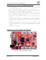
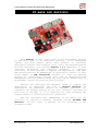
No.1: This is Connector DC-JACK to receive external Power
Supply 7-12V. It is free to arrange this connector in any
type because ET-BASE AVR EASY32U4 has Circuit that prevents
Connector Power Supply from converting.
No.2: This is Connector USB to interface with computer; it
is used to communicate data and develop program.
No.3: This is LED to show status of receiving data(RX) and
transmitting data(TX) for board.
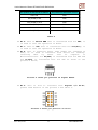
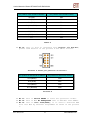
No.4: This is Port to interface with Analog Input A0-A5 or
Digital I/O D18-D23 as shown in the picture 2 and table 1
below;
Picture 2 shows pin position of A0-A5.
Pin position in the format of Arduino
A0 or D18
A1 or D19
A2 or D20
A3 or D21
A4 or D22
A5 or D23
Pin position in the format of AVR
PF7
PF6
PF5
PF4
PF1
PF0
Table 1
•
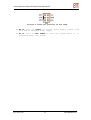
No.5: This is Port to interface with Digital I/O D8-D13 as
shown in the picture 3 and table 2 below;
Picture 3 shows pin position of D8-D13.
ETT CO.,LTD
-3-
www.etteam.com