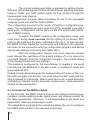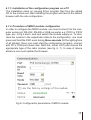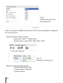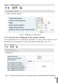
1
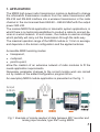
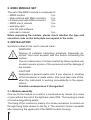
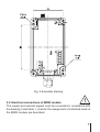
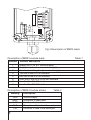
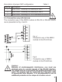
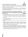
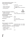
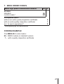
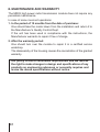
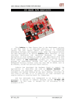
High power radio transmission module MR03 type User’s manual CONTENTS 1.APPLICATION..................................................................................5 2.MR03 MODULE SET........................................................................6 3.INSTALLATION................................................................................6 3.1 Module assembly......................................................................6 3.2 Connection diagrams ..............................................................7 3.3 Connection way with devices . ...............................................9 3.4 Requirements for lead connections ....................................10 4.PRINCIPLE OF OPERATION OF MR03 MODULE........................11 4.1 First start of MR03 module....................................................12 4.1.1 Installation of the configuration program on a PC ..........13 4.1.2 Procedure of the MR03 module configuration ...............13 4.1.3 List of displayed errors in the systemic window .............15 4.1.4 Prescription concerning radio transmission or sending-receiving devices which can be used without permission .........................................................16 5.Accessories ............................................................................17 6.TECHNICAL DATA . ......................................................................19 7.ORDER CODES ............................................................................21 8.MAINTENANCE AND WARRANTY ..............................................22 4 1. APPLICATION TheMR03highpowerradiotransmissionmoduleisdestinedtochange theinformationtransmissionmediumfromthecabletransmissionwith RS-232andRS-485interfaceintoawirelesstransmissionintheradio channelinthenon-licensedband869.40–869.65MHZwiththeoutput power500mW. ThemoduleMR03findsapplicationintelemetricsystemapplications,in whichthereisnotechnicalpossibilitiestoconductacabletoconnectdevicesinawirednetwork.Insuchcases,themoduleisusedasabridge whichpartiallywillcarryoutthetransmissionthroughtheradioway. ThemaximaloperationrangeoftheMR03moduleis1.5kminaverage, anddependsontheterrainconfigurationandtheappliedantenna. AccessibleMR03workingmodes: ltransparent, lmultipoint, lpoint-to-point, allow the creation of an extensive network of radio modules to fit the needsapplicationrequirements. Necessaryparameterchangestothecorrectmoduleworkarecarried outbymeansoftheaddedconfigurationprogramECon. AnexemplaryMR03moduleapplicationispresentedonthefig.1. 2x input 4-20 mA SM1 MR03 MR03 KD7 2x output 4-20 mA Fig1.ExampleofremotereadoutofdatabetweenKD7recorderand analoginputmodule,typeSM1usingMR03. 5 2. MR03 MODULE SET The set of the MR03 module is composed of: − MR03 module 1 pc. − Stub antenna with SMA connector 1 pc. − Antenna wire with SMA connector 1 pc. − MR03 user’s manual 1 pc. − warranty card 1 pc. − mini CD with software and user’s manual 1 pc. When unpacking the module, please check whether the type and execution code on the data plate correspond to the order. 3. INSTALLATION Symbols located in this user’s manual mean: WARNING! Warning of potential, hazardous situations. Especially important. One must acquaint with this before connecting the module. The non-observance of notices marked by these symbols can occasion severe injuries of the personnel and the damage of the module. CAUTION! Designates a general useful note. If you observe it, handling of the transducer is made easier. One must take note of this, when the instrument is working inconsistently to the expectations. Possible consequences if disregarded! 3.1. Module assembly One can fix the module on a wall or a construction by means of a screw or glue without the lost of the tightness class IP54. The housing is made of a self-extinguishing plastic. The fixing of the module by means of a screw connection is carried out through fixing holes shown on the fig. 2. The access to holes is possible after removing the upper part of the MR03 module housing. Fig. 2 Assembly drawing 3.2. Electrical connections of MR03 module The supply and external signals must be connected in compliance with the drawing 3 and table 1, in which the assignment of individual leads of the MR03 module are described. ZW1 ~ Fig.3 Description of MR03 leads Description of MR03 module leads Terminal Terminal description 1 2 3 4 5 6 7 8 Supply line (+ for d.c. current supply) Supply line (- for d.c. current line supply) Functional earthing line (d.c. current supply) TxD line of the RS-232 interface RxD line of the RS-232 interface GND line of the RS-232/RS-485 interface Line B of the RS-485 interface Line A of the RS-485 interface Description of MR03 module diodes Table 2 Marking Description PWR RxRF TxRF RxD TxD Module supply Reception of radio data Emision of radio data Reception of data from the serial port Emission of data to the serial port Table 1 Description of jumper ZW1 configuration Table 3 Marking Description 1 Short circuit – switching of a substring for line A 2 Short circuit – switching of a substring for line B 3 Short circuit – switching of a 150 Ω termination for line A-B 3.3. Connection way with devices The connection way of the MR03 module to RS-232 or RS-485 interfaces is presented on fig. 4 and 5. Fig. 4 Connection way of the MR03 module to the RS-232 bus Fig.5. Connection way of MR03 module to the RS-485 bus. Caution: Because of electromagnetic interference, one must use shielded wires to connect signals of the RS-485 interface. The shield must be connected to the earthing terminal in one point. The supply must be connected by a two-wire cable of appropriate wire diameter. It is recommended to use an additional protection in the shape of a fusible cut-out. 3.4. Requirements for lead connections Different interference sources practically occurring, interact with the module in a continuous or pulsing way from the supply network side (because of other device actions). The level of this interference should be reduced to a value lower than the module fastness threshold, first of all through the appropriate installation of the module in the object. In order to obtain a full module resistance against electromagnetic interference in an environment of unknown interference level, it is recommended to observe following principles: lThere should be a switch or a circuit breaker in the building installation. This element should be situated near the device, easy accessible for the operator. It should be marked as the instrument switching the device off. l do not supply the module from the network, near devices producing high pulse interference, l apply network filters for a group of modules servicing the same object, l apply the general principle, that wires (group of wires) leading different signals should be led in the highest possible distance between them (not less than 50 cm) and the crossover of such groups of wires made at a right angle (90°). l Taking into consideration electromagnetic interference, one must use shielded wires to connect RS-485 interface signals. The shield must be connected to the protective terminal in a single point. The supply must be connected by two-wire cable with a suitable cross-section ensuring its protection by means of a cut-out. 10 4. PRINCIPLE OF MR03 MODULE OPERATION The MR03 radio transmission module enables the radio communication of devices equipped in an RS-232 or RS-485 serial port and USB converter into RS-232 or RS-485, e.g. PD10 or PD12 type. The communication with RS-232 or RS-485 interface can be carried out at rates from 1200 bits to 115.2 kbits. The radio transmission is realized in the shape of data packages. The module allows to transmit data of maximal length 256 bytes. The data transmission is carried out in following way: data bits are collected from the serial port and are rewritten to the reception buffer. After an appropriate time (“time out”) from the transmission end, placed data in the buffer are prepared to be transmitted on radio links. In order to transmit data, frames are created, the structure of which depends on the selected working mode. The radio module can work in the transparent or package mode: “multipoint” mode (data are sent from one module and are received by all modules being in the range) or in the “point-to-point” mode, where data are sent to a define device. In transparent mode the data aren’t buffered but sent directly to the radio interface in packets of 60 bytes. Due to the lack of buffering and packaging the continuity of the data will be not maintain, and the spacing between the blocks of data can range up to 150 ms. In package mode („multipoint”, „point to point”) sent data is preceded by a special header. Data of the package heading, including necessary information for data exchange are additionally protected by CRC checksum.Data received from the serial interface during the radio transmission are not protected by the checksum. The reception of radio data consists on the reception of transmitted packages and their transmission to the output buffer of the serial interface. The reception module verifies the CRC checksum of the heading during the reception. After the heading reception and verification of its contents in accordance to the set working mode, data are sent in the serial interface. If a CRC error is discovered, the package is not received. In the case of point-to-point working mode, data originating from the same sender are transmitted in the serial interface. By the „multipoint” operating mode the group address is checked and the data from the current group of devices are received. 11 The current module work state is signaled by lighting diodes: RxD and TxD diodes signals the flow of data through the serial interface, however RxRF and TxRF diodes signal the flow od data through the transmission radio channel. The configuration program takes advantage of one of the accessible computer serial port and the module MR03. The configuration is carried out by means of the ECon configuration program. The configuration program uses one of the available computer’s serial ports. Configuration can be done via RS-232 and RS-485 interfaces of MR03 module. To switch the MR03 module in the configuration mode, one must press during three seconds (till the lighting of all diodes) SW1 push on the plate and the place indicated on the fig.3. In that moment, the MR03 module breaks the normal work and transits to the expectation state for the connection with the configuration program and admits appropriate settings of its serial port (9600, 8N1). After the configuration change, one must make the module reset through the switching of the supply voltage off or by giving the command “Restart” from the configuration program. The module restart in the standard mode with new settings. The module is configured by the manufacturer to operate in the serial port with the rate 9600 bit/s in the 8N1 mode, in “multipoint” mode and group address 255. Default module parameters can be restored without the use of the configuration program. For this aim, one must press the SW1 push and holding it pressed for 6 seconds. After 6 seconds occure a quick extinction and lighting of diodes, and the automatic module reset – what means the charge of new parameters. 4.1. First start of the MR03 module At the first start, the MR03 module requires the setting of following parameters: module working mode, signal power and channel number for the radio transmission. Moreover, it is indispensable to set serial port parameters: rates and transmission mode. The added ECon program to the module set allows the user to configure the MR03 radio module in an easy and simple way. 12 4.1.1. Installation of the configuration program on a PC The installation relies on copying ECon program files from the added CD to the module set. After installing the program will launch the default browser with the site configuration. 4.1.2. Procedure of MR03 module configuration In order to configure the MR03 module, one must connect it to the computer serial port: RS-232, RS-485 or USB converter e.g. PD10 or PD12 type, acc. to fig 4 and 5, and next switch the module supply on. To introduce the module in the expectation state to the configuration, one must press and hold the SW1 push during three seconds (till the lighting time of all diodes). Next, one must start the configuration program, connect with PC’s COM port (baud rate: 9600 b/s, mode: 8N1) and choose the appropriate type of the radio module (see fig. 6, 7). In case of device absence one must update the firmware. Fig.6. Configuraiton parameters of MR03 module. 13 Fig. 7. MR03 selection from the device list. After choosing the MR03 device from the list the parameters configuration can be done. - Serial port parameters (Fig.8): - baud rate (1200...115200 bit/s) - transimission mode (8N1, 8N2, 8E1, 8O1). Fig. 8. Settings of serial port. - Radio port parameters (Fig.9): - module operating mode, - 3 transmission channels, - 3 power levels. 14 Fig. 9. Settings of radio port. 4.1.3. List of errors displayed in the system window In the „Miscellaneous” of configuration software, one can read the status of errors and perform reset operation or restore the default parameters. (Fig. 10) Fig. 10. View of the status and reset buttons and the default settings. 15 4.1.4. Prescription concerning radio transmission or sendingreceiving devices which can be used without permission. The transmitter activity is defined by the transmitter activity coefficient – we understand by that the proportional transmission time relation in one or many carrier frequencies to the device operation time in 1 hour’ period. For the frequency of the MR03 radio module (869.4 MHz – 869.65 MHz) a large transmission activity has been assigned. It is the activity for which: l The transmission efficiency coefficient is higher than 1% and lower than 10% l The maximal transmission connection time is equal 36 seconds l The minimal transmitter disconnection time is equal 3.6 seconds. The conformity with the above ordinance must be obtained on the level of the transmitting-receiving system. The manufacturer does not be responsible for the use of radio modules inconsistently with the ordinances proper for the operational use place. 16 5. accessories The standard MR03 module is equipped with a stub antenna with SMA connector. In order to increase the range it is recommended to use a directional antenna in according to the table 4. No. 1. Ordering code Picture 0929-300-010 Name Description Antenna 10 - elements Wire: 10m Connector: SMA Frequency range [MHz]: 850-960 Gain [dB] : 13.5 F/B Ratio [dB]: 26 Polarization Type: Vertical Number of elements: 10 Input Impedance [Ω]: 50 Weight [kg] : 0.7 Lenght [m] : 0.7 Beamwidth H [o] : 32 BeamwidthV [o] : 34 17 2. Ordering code Picture 0929-300-014 18 Name Description Antenna 20 - elements Wire: 10m Connector: SMA Frequency range [MHz]: 850-960 Gain [dB] : 16.5 F/B Ratio [dB]: 26 Polarization Type: Vertical Number of elements: 20 Input Impedance [Ω]: 50 Weigth [kg] : 0.9 Lenght [m] : 1.7 Beamwidth H [o] : 25 Beamwidth V [o] : 26 6. TECHNICAL DATA Serial port: l RS-232/RS-485 interface - data format - baud rate 8N1, 8N2, 8E1, 8O1 1200 - 115200 bit/s Radio channel: - carrier frequency - power - sensitivity of the receiver - baud rate - transmission range in a right line (open area) - number of channels - antenna output 2000 m 3 50 Ω SMA Time to obtain the operating readiness since the moment of supply connection < 2s Receive buffer size 255 B Maximal delay time of transmission by a pair of MR03 modules 3 s (when transmitting 250 B data) 869.425 MHz 869.450 MHz 869.475 MHz 869.500 MHz 869.525 MHz 869.550 MHz 869.575 MHz 869.600 MHz 869.625 MHz 20 dBm, 25 dBm, 27 dBm >-103 dBm 2400 bit/s 19 Power absorbed by the module 9 VA Rated operating conditions: − supply voltage − ambient temperature − relative air humidity − working position 8... 30 V d.c. 12...30 V a.c. 50...60 Hz - 20...23...55°C < 95% inadmissible condensation any Storage and transport conditions: − ambient temperature - 40... 70°C − relative air humidity < 95% inadmissible condensation Ensured protection degree by the housing: − from the frontal housing side IP 54 − from the terminal side IP 54 Dimensions 115 ´ 65 ´ 40 mm (without the mounted antenna) Weight 400 g Electromagnetic compatibility: – noise immunity ETSI EN 301 489-1 V1.8.1:2008 – emission of radio noise ETSI EN 301 489-1 V1.8.1:2008 Safety requirements acc. to EN 60215 standard − installation category III − pollution degree 2 − maximal voltage in relation to earth 50 V 20 7. MR03 ORDER CODES MR03 high power transmission module Version: standard custom-made * Acceptance tests: without an extra quality inspection certificate with an extra quality inspection certificate acc. to user’s agreement * XX X 00 XX 0 1 X * after agreeing by the manufacturer CODING EXAMPLE The MR03-00-1 code means: 00 – MR03 module in standard version 1 – with a quality inspection certificate 21 8. MAINTENANCE AND WARRANTY The MR03 high power radio transmission module does not require any periodical maintenance. In case of some incorrect operations: 1. In the period of 12 months from the date of purchase: One should take the modul down from the installation and return it to the Manufacturer’s Quality Control Dept. If the unit has been used in compliance with the instructions, the Manufacturer warrants to repair it free of charge. 2. After the warranty period: One should turn over the module to repair it in a certified service workshop. The disassemby of the housing causes the cancellation of the granted warranty. Our policy is one of continuous improvement and we reserve the right to make changes in design and specifications of any products as engineering advances or necessity requires and revise the above specifications without notice. 22 23 tel.: (48-68) 45 75 100 (exchange) fax: (48-68) 45 75 508 e-mail: [email protected] http://www.lumel.com.pl 24 Export Department: Tel.: (48-68) 45 75 302 or 304 Fax: (48-68) 325 40 91 e-mail: [email protected] MR03-09C “LUMEL” S.A. ul. Słubicka 1 65-127 Zielona Góra - Poland