1
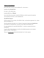
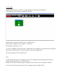
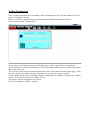
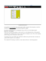
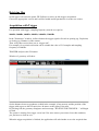
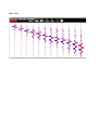
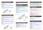
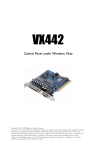
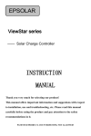
JEA247ESAC SEISMOGRAPH User Manual Software Installation Refer to the folder / directory of the installation file , whose name is: Installation Disk JEA24TESAC In it there is a file with the name : Installing USB Drivers FTDI.pdf Open it and follow the prompts to install the USB drivers needed to operate the equipment. After installation of the driver, run the installation file: JEA247ESACSetup.exe Will be created in C drive (default ): JEA247ESAC folder , with inside the application file , with the name: JEA247ESAC.exe . Since the application also makes use of a software for geoseismic interpretation SmartRefract, (wich makes use of acquired data) , you need to copy a folder in the following way . Go to the installation file: Setup Disk JEA24TESAC , in which is contained the directory: SmartRefract . Copy this folder inside the directory created by the installation program on your computer (which is usually c: JEA247ESAC ) Then go to www.java.com and download and install “java” in the computer. FIRST CONNECTION Please read carefully this section. After you have installed the USB driver and application JEA247ESAC (see file "Install USB Driver FTDI.pdf"), connect the power unit (MOM) to your PC, using the USB wire. MOM Unit MOM Unit connected to PC and cable Verify PORT Launch the application jea247esac.exe that should be in directory JEA247ESAC. Once launched, you will notice something like this: In the green box appears the RS232 ports available on PC. (which in this example are the number 1, 14 and 16). Port numbers range from 1 to 16. To remove ambiguity about which port is dedicated to the equipment, just disconnect the USB port and run the software again. The correct number will be that disappeared. The other parameters are the default ones. Note: It 'still possible that at the first plugging of the device (MOM), the operating system decides to assign a different number (over 16) to the port. In this case, the port would not appear in the green box, and you have to change its number. Go to the Control Panel System Device Manager Ports (COM & LPT) In this example, port 20 can not be seen, to change the number to go to USB Serial Port (COM20), right click, Properties, Port Settings, Advanced, Number of the COM port, then set a number less than or equal to 16. Important: It is necessary to vary the value of "latency time" , which is measured in msec. It is related to data transmitted from device to PC. The equipment connected to the USB socket will wait for a time equal to the "time-lag" between one packet of data and the next. It is necessary to lower this value to 1 msec. Connect the USB cable to MOM (it may be off). Open the System control panel System Hardware Ports (Com & LPT) and select the port number corresponding to the one used, right-click, go to Properties, Port Setting, Advanced. The latency time is now set to 1 msec. In the case of transmission from a PC to the device, the protocol is already structured to transmit packets employing a time of 1 msec or greater. Connecting Sections The JEA247ESAC consists of 1 or more cable sections; each section is composed of 24 units/channels. The first unit is characterized by a number starting with 1. Each cable section has in fact a progressive numeration: from 1 to 24, 25 to 48, 49 to 72 etc. ..., being composed of 24 units . You can connect to the MOM as many section as you desire (for a maximum of 5, i.e. 120 channels). Here you can see a layout of several sections and their (yellow) geophones. The last section of the seismic cable must have the termination inserted, as shown: Termination simply consists of a resistor of 120ohm, necessary for correct line termination of cable. If you do not terminate the line in this way, signal reflections make impossible any transmition, Between two section a Reapeter must be inserted. The box bear a display for battery charge level; verify that its value is more than 11v, otherwise recharge it. Respect the In/Out order. The new section must be connected to Out connector. Repeater Then power up the power unit (MOM). Voltage should be about 11/12v. (If voltage on display is less than 11v, recharge). Each unit will begin to flash. In this manual, the term unit or channel denote the same thing, as each box orange/blue denotes a unit and also a channel. Setting Parameters Once you have entered the correct number of the communication port, enter the number of units in the box: Geophones Number. Before you acquire, channels must be enabled and their identification number defined. Select from the menu "CHANNELS": As you can see, 24 channels have been labelled (if you exit this setup will be remembered). All 24 channels are enabled (check below). Click on the others cable sections to enable and number them in the same way. The circle/dot in the top of each unit represents the choice of the place to connect the trigger; verify that some unit has this option checked, otherwise you can’t get any signal acquired. In this example has been set a sampling frequency of 4000Hz, for a number of samples per channel equal to 256 (open the Parameters window to set). As is shown, the acquisition lasts for 64 msec. In fact, 256 samples / 4000Hz = 64 msec. Acquisition Parameters It is possible to see in real time the system acquires while it acquires all the channels set, but first remember to Set all Channels and to check the option for trigger. By default, the amplification is "autoranging", then you will see even the slightest signal. Press now "GO running". If there are not connected geophones, what you will see is the background noise of the apparatus. All graphs will be updated as fast as lower is the number of samples set (now 256), as the sampling and receiving process will lasts less with less data. To quit the process, press STOP; units will flash in a different way and after about 2 seconds, the system will be ready for a new command. The command "GO running" is usefull to verify connection between units and geophones. Retriving files On the upper left corner the menu: FILE allows to retrive an old (trigger) acquisition. Choose the appropriate .txt file and it will be loaded and all parameters set to the new values. Acquisition with Trigger For operation with trigger, sampling frequency must be set equal to: 1000Hz, 2000Hz, 4000Hz, 8000Hz, 16000Hz, 32000Hz In the "Parameters" window, define whether the trigger signal will work in opening (eg. Explosion) or closing (eg. Hammer) of the contact. Then verify that a unit as been set as “trigger unit”. For example, for a seismic refraction can be suitable the value of 512 samples and sampling frequency of 2000Hz. TRIGGER and press the GO button. Window of geometry will show: Set the distance between geophones (which in the example is four meters) and the position of the trigger with respect to the first unit (now 46 meters to the right of first unit). By clicking OK, the geometry disappears and a message "WAITING FOR TRIGGER ..." will begin to flash. The system is waiting for a trigger event, but if for some reason you want to leave this condition, you just have to click on exit. When the trigger acquisition is finished, the application will ask whether to save the acquired data. If you decide to save, two versions of the file will be saved, one with extension Sg2 and the other with extension txt. File.txt will be useful in case you want to review recently file previously saved. Below is an example of acquisition with 96 channels: Moving the mouse over a track and clicking, in the CH box will be displayed its number. Moving the mouse over a point in a track, in a window will be visible the relative time from trigger instant. Acquisition without triggering If the sampling frequency is equal to 500Hz or 250Hz, the trigger function is disabled, but the acquisition is possible for a long time, for 24 channels maximum. The memory resides in the hard disk of the PC. Acquisition time may be: Sampling frequency of 500Hz 2 hours 51' max Sampling frequency of 250Hz 5 hours 42' max To start Acquisitions without trigger select the "Continuous sampling". In the following example has been set a sampling frequency of 500Hz, for a time of acquisition of 20m and 5 sec. Clicking on START acquisition begins and a progress bar will indicate the progress of the process. At the end you have to save the file in .SGY format. STACKING In the goal of reducing the Gaussian noise, it is theoretically sufficient to mediate. The STACKING do this, as it lets you add together the traces acquired (through trigger) at successive times. The resulting signal should be more clean, as long as the trigger is always carried out in the same exact condition and nothing has changed in the geometry. To acquire with the method "Stacking", go to the menu and select stacking. The graph will become blue. At every triggering, tracks will be added together. After each triggering will be shown "Keep on staking?" Answer no, it ends the process of stacking and the file acquisition can be saved REFRACTION From Menu select: REFRACTION. You are asked to write the project name and then to begin acquiring in trigger mode. After each acquisition, enter the file name and save it if satisfied. Then you have to decide if the project is ended or to keep to perform the acquisition process. When the project will be terminated, the processing software SMARTREFRACT will open automatically. If the open windows shows empty, go to menu: Tools Plugins Installed and verify that all is installed. SPECTRUM In the menu you can select "Spectrum", to carry out the spectral analysis of a track. In following example has been selected track 1. Moving the mouse over the graph, we can determine the value of the frequency accurately. Being 2000Hz the acquisition frequency, the maximum frequency of 1000Hz is displayed in the graph, in accordance with the sampling theorem. DISPLAY This menu is only active in the acquisition triggered. Going to the menu "Display", you can choose the type of visualization of the acquired traces. For example, the following shows three different views: normal: black: Blue / Red: "File" menu: From the "File" menu, you can reload the acquisitions done in the "Trigger" mode. Go to the folder where you saved the files relating to previous acquisitions and download the file with the extension .txt. Files xxx.txt and data_trigger.txt The application creates, for each acquisition with trigger, a file: data_trigger.txt and another: xxx.sgy, and xxx.txt. The name xxx must be provided by the user. File: data_trigger.txt is updated every acquisition and located in JEA247ESAC directory; it is necessary for internal use. In running operation any file is saved. SMARTREFRACT See www.vs30.it About this software: is free for refraction postprocessing (GRM method) and also the customer have the right for internet assistance for any problems concerning postprocessing. Special DOLANG Service Is available to make the processing, upon payment of a small amount. Sampling Rate To perform a correct acquisition should be thoroughly learned what it means "signal", what is its spectrum, filtering, reconstruction of signal from its samples, sample rate etc ...., otherwise you may set the parameters without understanding why and do not correctly interpret what happens. The basic parameters of the process of acquisition is the sampling frequency (Fs, from sampling frequency) and resolution (see below). The reciprocal value of Fs is the sampling interval (Ts, by sampling time). In the application, in the Parameters window, it acts directly on Fs (Hz) and as a result, of Ts (milliseconds). To find out how long is the acquisition process, the formula is as follows: Acquisition Time = Number of samples / Fs or Acquisition Time = Number of samples x Ts For example, if I want a long acquisition time at a high Fs, I expect a large number of samples. It is not simple to deal with a large number of samples; for cases where it is required a long period of acquisition, a low Fs is used. A basic rule of sampling is that Fs must be at least twice the highest frequency contained in the signal to be acquired (Nyquist theorem). If the rule is broken, the acquired signal contains errors (aliasing). By the nature of the signals to be acquired, which are coming from a geophone, the spectrum barely reaches a few hundred Hz, starting from a minimum of a few Hz, depending on the geophone used, thus not requiring a high Fs. So in the case of a geophone that, when triggered, it is expected to provide signals until 300/400Hz, the sampling frequency must be at least twice, or 800Hz. This consideration is only theoretical, because in reality, to acquire a signal that has any practical value, you must acquire a much higher frequency. Otherwise, the available samples would be too few to easily reconstruct the original signal. The application JEA247ESAC acquires always at Fs = 32000Hz. The lower sample rates are derived from the actual 32000Hz averaging. For example the frequency of 4000 Hz is obtained from the average of 8 samples. This process of "downsampling" carries out an average on the signal that corresponds to a low pass filtering, which is useful to diminish any higher frequencies and noise present. Nevertheless, to acquire 250Hz, the minimum expected Fs, exposes us to possible aliasing errors in case in the signal was a strong component over the 125Hz. A hardware filter on this unit provides to eliminate / mitigate frequencies not useful coming from geophone. In sampling without trigger, even if you can acquire at 250Hz, it is better to opt for the higher frequency of 500Hz, to avoid the danger of aliasing error. Resolution The resolution is determined by the number of bits of the AD converter. The higher the resolution, the more the sampling system can "see" small signals. JEA247ESAC uses a 24-bit converter, so if it is assumed that the geophone can give a maximum signal between 1V and -1V, matching the range of AD converter, the theoretical minimum measurable signal is: 2volt / 2 ^ 24 = 119 NV = 0.119 millivolts microvolts = 0.000119 = 0.000000119 volts Although this measure is theoretical and is incredibly low, the amount of bits gives us another factor to measure the goodness of an acquisition. An acquisition at 16-bit, at least theoretically, is 256 times worse than at 24-bit. Signal / noise ratio This parameter is very important , as it can measure and tell us what is actually possible to discriminate a signal acquired in the presence of noise. The problem to recover a signal from the noise is universal and always present in every situation . If you remove the geophone and short-circuit the inputs of the unit , the signal only noise source is internal to the equipment, or from electromagnetic interference , and eventually due to the digital conversion process , which gives rise to the quantization noise. The quantization noise decreases with the increase of the bits of conversion. This noise is reduced by the averages that are performed to get Fs from 32000Hz . For example . at 4000Hz there is a quantization noise slightly lower than 8000Hz . This process of noise reduction is called " Noise Shaping " . The equipment in question provides a value for this ratio , better than 124dB for Fs = 1 kHz or so, which is a very good result . If the noise was completely invalid , and this was only the quantization noise , with 24 bits for the relationship we have approximately 144dB , which is a theoretical ideal value , even remotely accessible . This value is often not very seriously stated on many devices , along with other parameters more or less invented. Technical Data of JEA247ESAC > WATER PROOF < Structure PC connected by USB/RS485 to sampling units Max sampling units number 240 – for more than 24 a repeater is needed Resolution 24 bit AD Converter Sigma Delta Sampling Frequency (Fs) 250Hz, 500Hz, 1000Hz, 2000Hz, 4000Hz, 8000Hz, 16000Hz, 32000Hz Number of samples Fs > 500Hz, max Number 16384 Number of samples Fs = 500Hz/250Hz max number 5M samples Sampling duration Fs = 500Hz about 2h 50m (24 ch) Fs = 250Hz about 5h 40m (24 ch) Trigger Each unit can be connected to a trigger wire of desired length, to work in opening or closing contact. Power Rechargeable battery unit included in USB/RS485 box – more than 7h autonomy with 24 units in continuous work. First 24 ch powered by USB PC Bandwidth Up to 1 KHz, 2 poles low pass filter, DC component rejection Input impedence 1500 ohm Nyquist frequency 16000Hz at every Fs Signal/RSM noise ratio Connection >124dB at Fs=1000Hz, input shorted Units serially connected to PC by RS485 standard, at 1MHz baudrate Application for Windows XP, 7 and 8 allows easy setting of all acquisition parameters and produces a .sgy - seg2 file for further analisys Each Unit (corresponding to a channel) can be connected to a geophone with desired specifications Software Geophones