1
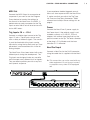
User Manual
Nord Drum 2
Part No. 50416
Print Edition 1.0
Copyright Clavia DMI AB 2013
The lightning flash with the arrowhead symbol within
an equilateral triangle is intended to alert the user to the
presence of uninsulated voltage within the products enclosure that may be of sufficient magnitude to constitute
a risk of electric shock to persons.
CAUTION - ATTENTION
RISK OF ELECTRIC SHOCK
DO NOT OPEN
RISQUE DE SHOCK ELECTRIQUE
NE PAS OUVRIR
Le symbole éclair avec le point de flèche à l´intérieur d´un triangle
équilatéral est utilisé pour alerter l´utilisateur de la presence à
l´intérieur du coffret de ”voltage dangereux” non isolé d´ampleur
suffisante pour constituer un risque d`éléctrocution.
CAUTION: TO REDUCE THE RISK OF ELECTRIC SHOCK
DO NOT REMOVE COVER (OR BACK).
NO USER SERVICEABLE PARTS INSIDE.
REFER SERVICING TO QUALIFIED PERSONNEL.
The exclamation mark within an equilateral triangle is
intended to alert the user to the presence of important
operating and maintenance (servicing) instructions in the
literature accompanying the product.
ATTENTION:POUR EVITER LES RISQUES DE CHOC ELECTRIQUE, NE
PAS ENLEVER LE COUVERCLE.
AUCUN ENTRETIEN DE PIECES INTERIEURES PAR L´USAGER.
CONFIER L´ENTRETIEN AU PERSONNEL QUALIFE.
AVIS: POUR EVITER LES RISQUES D´INCIDENTE OU D´ELECTROCUTION,
N´EXPOSEZ PAS CET ARTICLE A LA PLUIE OU L´HUMIDITET.
Le point d´exclamation à l´intérieur d´un triangle équilatéral est
employé pour alerter l´utilisateur de la présence d´instructions
importantes pour le fonctionnement et l´entretien (service) dans le
livret d´instructions accompagnant l´appareil.
Instructions pertaining to a risk of fire, electric shock or injury to persons.
IMPORTANT SAFETY INSTRUCTIONS
SAVE THESE INSTRUCTIONS
Warning - When using electric products, basic precautions should always be followed, including the following:
1) Read these instructions.
10) Protect the power cord from being walked on or pinched
particularly at plugs, convenience receptacles, and the point
2) Keep these instructions.
where they exit from the apparatus.
3) Heed all warnings.
11) Only use attachments/accessories specified by the manufacturer.
4) Follow all instructions.
5) Do not use this apparatus near water.
6) Clean only with dry cloth.
7) Do not block any ventilation openings. Install in accordance
with the manufacturer’s instructions.
8) Do not install near any heat sources such as radiators, heat
registers, stoves, or other apparatus (including amplifiers) that
produce heat.
12) Use only with the cart, stand,
tripod, bracket, or table specified by the
manufacturer, or sold with the apparatus.
When a cart is used, use caution when
moving the cart/apparatus combination to
avoid injury from tip-over.
13) Unplug this apparatus during lightning
storms or when unused for long periods of time.
9) Do not defeat the safety purpose of the polarized or
grounding-type plug. A polarized plug has two blades with one
wider than the other. A grounding type plug has two blades
and a third grounding prong. The wide blade or the third prong
are provided for your safety. If the provided plug does not fit
into your outlet, consult an electrician for replacement of the
obsolete outlet.
14) Refer all servicing to qualified service personnel. Servicing
is required when the apparatus has been damaged in any way,
such as power-supply cord or plug is damaged, liquid has been
spilled or objects have fallen into the apparatus, the apparatus
has been exposed to rain or moisture, does not operate normally, or has been dropped.
No naked flame sources, such as lighted candles, should be placed on
the apparatus;
Il convient de ne pas placer sur l´appareil de sources de flammes nues,
telles que des bougies allumées;
Do not use the apparatus in tropical climates.
L´appareil n’est pas destiné á étre utilisé sous un climat tropical.
Additional Safety Information
WARNING: To reduce the risk of fire or electric shock, do not expose
this apparatus to rain or moisture.
The apparatus shall not be exposed to dripping or splashing and that
no objects filled with liquids, such as vases, shall be placed on the
apparatus.
L´appareil ne doit pas étre exposé á des égouttements d´eau ou des
éclaboussures et de plus qu´aucun objet rempli de liquide tel que des
vases ne doit étre placé sur l´appareil.
The maims plug is used as the disconnect device and shall remain
readily operable.
Lorsque la prise du résau d’alimentation est utilisée comme dispositif
de déconnexion, ce dispositif doit demeuré aisément accessible.
Trademarks: The Nord logo is trademark of Clavia DMI AB. All other trademarks mentioned
in this publication are the properties of their respective holders.
Specifications and appearances are subject to change without notice.
Copyright © Clavia DMI AB
Nord Drum 2 User Manual
Channel Parameters
1 Stand holder & connections
Attaching the stand holder . . . .
Connections . . . . . . . . . . . . . . . . . . .
Left, Right Out . . . . . . . . . . . . . . . . . . . .
MIDI In . . . . . . . . . . . . . . . . . . . . . . . . . .
MIDI Out . . . . . . . . . . . . . . . . . . . . . . . . .
Trig Inputs CH 1 – CH 6 . . . . . . . . . . . . .
Power . . . . . . . . . . . . . . . . . . . . . . . . . . .
4
4
4
4
5
5
5
2 Getting Started
Connect a Nord Pad . . . . . . . . . . . .
Connecting pads . . . . . . . . . . . . . . .
Adjust Input sensitivity . . . . . . . .
Threshold . . . . . . . . . . . . . . . . . . . . . .
MIDI Channel . . . . . . . . . . . . . . . . . .
MIDI Note assignment . . . . . . . . .
Four Modes . . . . . . . . . . . . . . . . . . . .
Basic editing . . . . . . . . . . . . . . . . . . .
6
6
6
7
7
7
8
8
The Lower parameters . . . . . . . . . . . . . . 9
Solo Edit . . . . . . . . . . . . . . . . . . . . . . . . . 9
Memory Protect . . . . . . . . . . . . . . . . . . . 9
Storing . . . . . . . . . . . . . . . . . . . . . . . . . 10
Storing to a new location . . . . . . . . . . . 10
. . . . . . . . . .14
Distort . . . . . . . . . . . . . . . . . . . . . . . . . .14
Level . . . . . . . . . . . . . . . . . . . . . . . . . . . 15
Pan . . . . . . . . . . . . . . . . . . . . . . . . . . . . 15
Tone Parameters
. . . . . . . . . . . . . 15
Spectra . . . . . . . . . . . . . . . . . . . . . . . . .15
Wave . . . . . . . . . . . . . . . . . . . . . . . . . . 15
Dyn Timb . . . . . . . . . . . . . . . . . . . . . . . 15
Timbre . . . . . . . . . . . . . . . . . . . . . . . . . 15
Hi Decay . . . . . . . . . . . . . . . . . . . . . . . . 15
Punch . . . . . . . . . . . . . . . . . . . . . . . . . . 15
Decay . . . . . . . . . . . . . . . . . . . . . . . . . . 16
Type/Dyn . . . . . . . . . . . . . . . . . . . . . . . 16
Pitch . . . . . . . . . . . . . . . . . . . . . . . . . . . 16
Scl Pre . . . . . . . . . . . . . . . . . . . . . . . . . 16
Bend Range . . . . . . . . . . . . . . . . . . . . . 16
Bend Time . . . . . . . . . . . . . . . . . . . . . . 16
Click Parameters
. . . . . . . . . . . . . 16
Level . . . . . . . . . . . . . . . . . . . . . . . . . . . 16
Type . . . . . . . . . . . . . . . . . . . . . . . . . . . 16
Mix Parameter . . . . . . . . . . . . . . .
Shift Parameters . . . . . . . . . . . . .
Copy . . . . . . . . . . . . . . . . . . . . . . . . . . .
Paste . . . . . . . . . . . . . . . . . . . . . . . . . .
Panic . . . . . . . . . . . . . . . . . . . . . . . . . .
System . . . . . . . . . . . . . . . . . . . . . . . . .
MIDI . . . . . . . . . . . . . . . . . . . . . . . . . . .
Trig Type . . . . . . . . . . . . . . . . . . . . . . . .
Inp Thres . . . . . . . . . . . . . . . . . . . . . . .
Inp Sens . . . . . . . . . . . . . . . . . . . . . . . .
17
17
17
17
17
18
18
19
19
MIDI Operation . . . . . . . . . . . . . . . .19
Storing the memory content . . . . . . . .
Receive MIDI Dumps . . . . . . . . . . . . . .
Updating the Operating System . . . . . .
Website . . . . . . . . . . . . . . . . . . . . . . . .
3 Reference
17
19
19
20
20
The Panel . . . . . . . . . . . . . . . . . . . . .
11
Master Level . . . . . . . . . . . . . . . . . . . . 11
Program/Store . . . . . . . . . . . . . . . . . . 11
Storing a program . . . . . . . . . . . . . . . . 11
Program/Value LED display . . . . . . . . 11
Channel Select . . . . . . . . . . . . . . . . . . 11
Mute Group . . . . . . . . . . . . . . . . . . . . . 12
Edit Group . . . . . . . . . . . . . . . . . . . . . . 12
Input Trig Level LEDs . . . . . . . . . . . . . .12
Peak/Focus red LED . . . . . . . . . . . . . . 12
Trig/MG green LED . . . . . . . . . . . . . . . 12
Shift/Exit . . . . . . . . . . . . . . . . . . . . . . . 12
Lower Param/Repeat Tempo . . . . . . . 12
Dial . . . . . . . . . . . . . . . . . . . . . . . . . . . 13
Trig/Trig Level . . . . . . . . . . . . . . . . . . . . 13
Parameter buttons . . . . . . . . . . . . . . . 13
Noise Parameters
. . . . . . . . . . . .
Filter . . . . . . . . . . . . . . . . . . . . . . . . . . .
Filt Type . . . . . . . . . . . . . . . . . . . . . . . .
Dyn Filter . . . . . . . . . . . . . . . . . . . . . . .
Filt Res . . . . . . . . . . . . . . . . . . . . . . . . .
Atk/Rate . . . . . . . . . . . . . . . . . . . . . . . .
Env Mode . . . . . . . . . . . . . . . . . . . . . . .
Decay . . . . . . . . . . . . . . . . . . . . . . . . . .
Type/Dyn . . . . . . . . . . . . . . . . . . . . . . .
13
13
13
13
13
13
14
14
14
4 Appendix
Factory Soundbank . . . . . . . . . . .
21
Categories . . . . . . . . . . . . . . . . . . . . . . 25
4 | Nord Drum 2 User Manual OS v1.x
1
Stand holder & connections
Attaching the stand
holder
Connections
NORD PAD INPUT
POWER
The stand holder makes it possible to mount
the Nord Drum 2 on a stand that is equipped
with a clamp. The stand holder with its diameter of 23 millimeter is designed to fit with
most general purpose clamps.
CH
CH46
CH 5
CH 4
CH 3
CH2
CH 1
RIGHT OUT
LEFT OUT
PHONES
Phones
Connect a stereo headphone to the Phones
output. This is a 1/8" jack.
Left, Right Out
The L and R outputs are line level signals on
unbalanced ¼" jacks.
EE Always turn on the Nord Drum 2 first and
the sound system last, and the reverse
order when you wish to turn it off again.
EE The Nord Drum 2 is capable of producing sounds with a very wide and rapidly
changing dynamics and frequency ranges.
Be careful when you use the unit and
when you edit the sounds. Keep the
level at moderate settings, in order not to
overload a connected sound system by
making drastic changes with the available
parameters.
MIDI In
Connect the MIDI Input to a drum pad or
sequencer if you want to control the sounds
in the Nord Drum 2 via MIDI. The MIDI Input
is also used to update the unit with new
operating systems.
Chapter 1 Stand holder & connections MIDI Out
Connect the MIDI Output to a computer or
sequencer if you want to use the Program
Dump feature to transfer the settings to
the sounds in the Nord Drum 2 via MIDI. A
performance on pads connected to the Trig
Inputs or on a Nord Pad will also be transmitted as MIDI notes.
Trig Inputs CH 1 – CH 6
Connect a suitable signal source to the Trig
Input ¼" jacks. These inputs can be used
with a variety of different signals. The sensitivity and the threshold of the inputs can be
adjusted by using the Inp Sens and Inp Thres
parameters, read more about this in the following chapter.
The Nord Drum 2 has been tested with many
different pads during the development. The
Trig Inputs are designed to be very versatile
and to accept many different kinds of signals.
They are able to provide you with a very fast
and dynamic response.
If you experience double triggered sounds,
flams or a slow response from the Nord Drum
2, make sure that you adjust the Trig Type,
Inp Thres and Inp Sens parameters. Read
more on how to adjust these settings this on
page 6
Power
Connect the Nord Drum 2 power supply to
the Power input. If the original supply is not
available, use only a 12 volt DC, 250 mA
adapter, with a barrel type plug that has the
positive current on the tip. The outer diameter
of the plug is 5.5 millimeter and the inner
diameter is 2.1 millimeter.
Nord Pad Input
Connect a Nord Pad to the RJ45 connector,
using the cable that is supplied with the Nord
Pad.
EE This connection can not be used with any
other equipment. Do not try and connect
a computer or any other RJ45 equipped
unit
| 5
4
6 | Nord Drum 2 User Manual OS v1.x
2
Getting Started
Connect a Nord Pad
Adjust Input sensitivity
1 Use the supplied CAT-6 cable to
It is important to adjust the Input Sensitivity
when using pads from other manufacturers,
in order to be able to use the full dynamic of
the Nord Drum 2.
connect a Nord Pad to the Nord Pad
Input on the Nord Drum.
1 Strike the pad, listen to the sound from
the Nord Drum 2 and look at the Input
Trig Level LEDs for that particular channel. The LEDs indicate the strength of
the incoming trigger signal.
MM The Input Sensitivity will be automatically
set when a Nord Pad is detected.
If you want to add for example a kick
drum pad to the Nord Drum 2 while using
the Nord Pad, connect this pad to the
CH 1 input. The other inputs are disabled
when the Nord Pad is connected.
2 The red LED should be lit a bit longer
when you hit the pad with your strongest
force.
Connecting pads
1 Connect your pads to the six Trig Inputs
on the Nord Drum 2. The Trig Inputs can
be used with mono or stereo connectors.
CH 5
CH 4
CH 3
CH2
CH 1
In general, the factory sounds use Channel 1 for Bass drum sounds, channel 2 for
Snare and channel 3 to 6 for toms.
3 Press the Channel Select button to
move the solid red LED to the channel
that the pad is connected to. This is
called to move the Edit focus, you set
the unit to be ready to change the settings on that particular channel.
RIGHT OUT
LEFT OUT
PHONES
Chapter 2 Getting Started 4 Hold Shift and press the Inp Sens button
on the Nord Drum 2 panel. The red LED
above the button will start to blink to
indicate that the parameter printed
below the second row is active for
editing.
MIDI Channel
If you wish to control the Nord Drum 2 with
a MIDI controller, the MIDI channel and the
notes that this controller transmits must be
matched to MIDI channel of the Nord Drum 2
to trigger the four channels. The default MIDI
Channel is channel 10.
1 Connect a MIDI pad or other MIDI
5 Strike the pad and adjust the Input sensitivity by turning the Dial to match the
pad response and your striking force.
Threshold
If you have several pads or other pieces
in your kit that are mounted on the same
hardware, use the Inp Thres parameter to
eliminate any unwanted, accidental triggers
from other units.
1 Select the Channel that is receiving the
unwanted triggers.
2 Hold Shift and press the Inp Thres
controller to the MIDI Input on the Nord
Drum 2.
2 Hold Shift and press the MIDI Ch button
repeatedly to access the “Ch” setting.
3 Turn the Dial to select the MIDI channel
you wish to use.
MM The LED above the MIDI Ch button will
flash to indicate that your are editing System parameters.
4 Transmit a MIDI note or other message
from the MIDI controller. The incoming
channel will be displayed in the LED.
MM The Nord Drum 2 can only receive on one
MIDI channel at a time.
button.
MIDI Note assignment
3 Strike the pad or drum that causes the
unwanted triggers and raise the Inp
Thres value with the dial until the Nord
Drum 2 channel stops triggering.
4 Strike the pad that should trigger the
Nord Drum 2 to verify that the new
Inp Thres setting has not changed the
desired response.
When the Nord Drum 2 is shipped from the
factory, channels 1 to 6 are assigned to the
following MIDI note numbers: 60, 62, 64, 65,
67 and 69. Here is how to change this if you
wish:
1 Connect a MIDI pad or other MIDI
controller to the MIDI Input on the Nord
Drum 2.
2 Press the Channel Select buttons on
the Nord Drum 2 to select one of the
channels.
| 7
6
8 | Nord Drum 2 User Manual OS v1.x
3 Hold Shift and press the MIDI button
repeatedly until you see a “n” followed
by a number in the display.
4 Turn the dial to set the desired MIDI
Note Number for that channel.
5 Repeat steps 2, 3 and 4 to assign
the other channels to the additional
MIDI note numbers that the MIDI unit
transmits.
6 Press the Program button to Exit the
System edit mode.
Four Modes
When the display shows the letter P followed
by numbers, this is the Program Mode.
Programs are organized in Banks with 99
Programs each. Turn the Dial to select any of
the available programs.
The Edit Mode is active when one of the red
LEDs in the two rows below the LED and
above the buttons are lit and the display
shows one or two sets of numbers and/or
characters. This is when you can change the
settings of the selected parameter with the
Dial.
The Solo Edit Mode is active if you hold Shift
and press the Row Select/Solo Edit button.
Only the component that is currently being
edited will be heard when you trigger the
channel.
When one of the lower row LEDs are flashing,
this mean that the System Mode is active
where the parameter printed below the second row button is adjustable with the Dial.
Basic editing
The Nord Drum 2 has 6 channels, it can
produce 6 simultaneous sounds. Each one of
the channels has a complete and identical set
of parameters.
A sound in the Nord Drum 2 is created with a
blend of up to three components: Noise,
Tone and Click and the effects. Each one of
these components has their individual set of
parameters.
Tone
Input
Noise
Click
Tone/
Noise
Level
Drive/
Crush
EQ
Level/
Pan
Click
Level
The Tone can be described as the “body” of
the sound, the noise is a non-pitched addition with variable length and the click is the
very transient, like the contact sound of the
stick on whatever you are hitting. These components can be processed by effects, such a
distortion, equalizer and a repeat effect.
1 Use the Trig button in the lower right
corner to play the sound on one channel
at a time. Triggering sounds from the
panel are made with a fixed velocity.
If you have pads connected, these can
be used as well and will make the sounds
respond to the velocity of your playing.
2 Press the Channel Select button repeatedly to select one of the six channels.
The channel parameters are accessed with
the grid of two rows with eight buttons.
Chapter 2 Getting Started 3 A parameter is selected by simply
pressing a button. This will activate Edit
Mode and the display will show
parameter values.
1 Hold Shift and press the Row Select/
Solo Edit to activate the Solo Edit mode.
2 Strike a pad or use the Trig button to
4 To change the row to the lower set of
parameters, double-tap on a parameter
button or use the Row Select button to
the left.
5 Turn the Dial to change the setting of a
parameter.
6 Press the Channel Select button repeatedly to select which one of the six channels to edit.
The Lower parameters
15 of the buttons have additional parameters
assigned to them, indicated with red text.
These are displayed with dual values in the
display with the red parameter to the right.
1 The additional right value is changed by
holding down the parameter button and
then turning the Dial.
Solo Edit
The Solo Edit feature can be used to playback only the Noise, Tone or Click components when you select the parameters for
these. This allows you to edit the parameters
and only hear the particular component you
are working with in isolation.
hear only the component that is currently
being edited.
If you switch from one component to
another, the soloing will also be switched.
3 Press the Program button to exit the
Solo and Edit mode. The LED will show
a P followed by numbers.
Memory Protect
When the Nord Drum 2 is shipped from the
factory, storing programs to the memory is
not possible until you turn off the Memory
protection. This is done with one of the System parameters.
MM If the Memory Protect is On, the display
will show “Prot” when you try to Store a
Program
1 Hold Shift and press repeatedly on the
System button until “Pr On” is shown in
the display.
2 Turn the Dial to the “Pr Of” setting.
This will allow you to store programs
until this parameter is set to On again.
3 Exit the System mode by pressing the
Program button.
| 9
8
10 | Nord Drum 2 User Manual OS v1.x
Storing
Storing to a new location
When a Program has been changed, this is
indicated with a dot to the right of the
program number.
1 Hold Shift and press the Program/Store
If you select another program,
your edits will
be lost. If you
want to keep any
changes you have made, you have to Store
the edited program.
1 Hold Shift and press the Program/Store
button.
2 The display will start to blink.
3 Select a location for the new program
with the dial.
4 Press Program/Store again.
If you do step 4 without turning the Dial,
the edited program will be stored to the
current location.
button. The display will start to blink.
2 Use the Dial to pick a location for the
new Program.
3 Confirm your intentions by pressing
Program/Store a second time.
This method can also be used to make
copies of a Program.
Chapter 3 Reference 3
Reference
The Panel
Master Level
The Master Level controls
the overall output level
of the Nord Drum 2. This
is not a programmable
control.
Program/Store
Press the Program button to exit any other
mode and to enter the Program mode. The
LED display will show a P followed by two
numbers, the Bank and the Program There
are two Banks with 99 programs each in the
Nord Drum 2.
MM If a program has been edited but not yet
stored, this will be indicated by a dot in
the lower right corner of the LED.
Storing a program
made with numbers and/or characters. Most
parameters are indicated with dual settings,
one indicated to the right and the other to the
left in the display.
When you want to change one of the red
labeled parameters (for example Filter Type
LP in the illustration), hold down the “Lower
Param” button and turn the dial. You can also
hold down that particular parameter button
and turn the Dial. These lower parameters are
always to the right in the display.
Solo Edit mode is activated by holding Shift
and pressing the Row Select/Solo Edit button. The Solo Edit LED will blink and only the
component that is currently being edited will
be heard.
System mode is activated when the System
parameters are selected by holding Shift and
pressing a parameter button.
Channel Select
The process on Storing a Program is described on page 10.
Program/Value LED display
Program mode
is indicated with a
P, followed by
numbers. The first
number is the
bank, the second
number is the Program number.
Edit mode is
when a parameter
in the Nord Drum
2 is selected. The
presentation of
the settings will be
Press the Channel Select buttons repeatedly
to select the channel to be triggered with the
Trig button on the panel and/or to be edited
with the parameters. The red LEDs will indicate which channel is selected.
You can use pads to quickly select the
channel to edit, if no channel has been
previously selected with the Channel
Select button. If the button has been used
to manually select a channel, press the
Program button once to get back to the
quick-select-edit-channel-by-pads mode
(QSECBP™).
| 11
12 | Nord Drum 2 User Manual OS v1.x
Mute Group
Peak/Focus red LEDs
Hold Shift and
press the Mute
Group button to
select several
channels as part
of a Mute Group. The Mute Group will be
indicated by steady lit green LEDs. The Mute
Group allows you to mute the output of one
channel that is part of the group by playing
on any other channel in the Mute Group.
The Mute Group selection will be saved in a
Program.
The upper LEDs are red and will flash briefly
when a trigger input receives a strong signal.
It will be lit up in a longer duration when the
input receives an optimal, as-hard-as-youcan-strike signal. Solid red LEDs are used to
indicate an Edit Group.
Hold Shift and the Mute Group button for a
little longer to clear the Mute Group.
Shift/Exit
Trig/MG green LEDs
The lower LEDs are green and will blink on
Channel activity. They are also used as indicators when you create a Mute group.
Edit Group
Hold Shift and press the right Channel Select
button to add/select several consecutive
channels as an Edit Group. The selection
begins with the current channel and adds
one or more to the right of it depending on
how many times you push the button. An Edit
Group allows you to change the setting of
one parameter on all the grouped channels at
the same time.
MM Edit groups are not saved as part of
programs.
Hold Shift and the Edit Group button for a
little longer to clear the Edit Group.
Input Trig Level LEDs
The Shift button is used together with the
buttons to access additional parameters.
These additional parameters are identified
with the text below the buttons.
The Shift button can also be used to Exit a
Store operation, if you change your mind
about storing a program.
Lower Param/Repeat Tempo
Hold the Lower Param button and turn the
Dial to change the setting of the parameters
labeled in red.
Hold Shift and Repeat Tempo to change
the tempo of the repeats with the Dial. The
tempo range is from 30 to 1000 BPM.
The Input LEDs will flash to indicate the
activity in the six channels. A solid red LED indicates that a channel is selected for editing.
Chapter 3 Reference Dial
The Dial is used to select programs and to
change the setting of a selected parameter.
Noise Parameters
The noise filter and attack/decay parameters
can be used to sculpt the sound of the noise.
Filter
Trig/Trig Level
Use the Trig button to trigger a selected
channel from the unit itself. Hold Shift and the
Trig button to be able to adjust the Trig button’s velocity level with the Dial.
Parameter buttons
The Filter parameter is a control that sets the
frequency where the filter will begin to affect
the noise. The actual sound that is produced
depends on the Filter Type, see below.
Filter Range: 0 – 50
Filt Type
There are three filter types to choose from:
Low Pass, High Pass and Band Pass, all with
a 24 dB/octave slope.
Filter Type: LP, HP, BP
Dyn Filter
The parameters are accessed with the row of
eight buttons. Edit mode is activated as soon
as you press one of these buttons.
If a button activates a parameter in the upper row, a quick double-tap on the same
button or by pressing the Row Select button
will move the edit focus to the lower row
parameters.
Hold down the Lower Param button (or the
actual parameter button in question) and turn
the Dial to edit a lower parameter.
You can control the filter with the striking
force. This parameter is bipolar, you can set
a positive or a negative amount to open or
close the filter with the striking force.
Range: -19 to 0 to 20
Filt Res
Resonance is used to emphasize frequencies
around the filter cutoff frequency. This can be
perceived as making the sound thinner.
Range: 0 – 10
Atk/Rate
Increasing the attack makes the beginning of
the noise softer, it builds up in level. If the Env
Mode is set to any of the repeating modes,
this sets the rate of the repeats.
Range: 0 – 50
| 13
12
14 | Nord Drum 2 User Manual OS v1.x
Env Mode
Distort
The noise envelope (attack, decay) can be
set to a traditional, one shot behavior (Ad), It
can also be set to a looping behavior, which
means that it will repeat itself, the r1 to r3 and
c settings, during the decay.
This parameter adds distortion to the sound.
Range: Ad, r1, r2, r3, c
Range: 0 – 50
Type
Select between a tube amplifier type overdrive (dr) or a sample rate reduction (Sr).
Range: dr, Sr
Decay
The Decay parameter controls the length
of the noise. A higher value means a longer
noise.
Eq Freq
The onboard equalizer has an adjustable
frequency between 50 Hz and 12 kHz.
Range: 0 – 50
Type/Dyn
This parameter have two functions. Choose
between Exponential, Linear or a Gated curve
of the noise envelope. If you keep turning the
Dial you will be able to set an second decay
time, a time that will gradually be used when
you use more striking force. This second decay time can be either longer or shorter than
the “original” decay.
EQ value
Approx. frequency
4
125 Hz
8
250 Hz
15
500 Hz
25
1 kHz
33
2 kHz
MM If the Gain parameter is set to 0, changing
this parameter will have no effect.
Range: 0 – 50
Range: E, L, G, Exx, Lxx, Gxx
Gain
Use the gain control to boost or cut with up
to 24 dB at the EQ frequency.
Range: +/- 24
Type E
Type L
Type G
Repeat
Channel Parameters
Use the Channel parameters to add distortion, eq (tone control) and repeats to the
sound and to set the level and panning of the
channel.
Use the Repeat parameter to add delay-like
repeats. The tempo is set by holding the Shift
and Repeat Tempo buttons and turning the
Dial. For more repeats, set a higher value. At
20, the repeats will continue indefinitely.
The “rx” settings indicates a fixed number of
repeats. If you trigger the channel between
the repeats, these will be added and repeated together with the original sound.
Range: 0 – 20, rx
Chapter 3 Reference MM If the Amount parameter is set to 0,
changing this parameter will have no
effect.
Wave
Description
A1 - A4
Analog style waveforms:
Sine, Triangle, Sawtooth and
Square.
H1 - H7
Harmonic waveforms.
P1 - P6
Percussive waveforms.
d1 - d8
Drum head style waveforms.
C1 - C2
Cymbals.
Amount
This parameter sets the amount or level of
the repeats.
Range: 0 – 20
Level
This sets the volume of the channel.
Range: 0 – 20
Pan
This sets the position of the channel in the
stereo panorama from left to right.
Range: -10 – 10
Tone Parameters
Dyn Timb
The waveforms can be processed with the
Timbre parameter which is a lowpass filter
that can make the Tone duller. The Dyn Timb
allow you to open this filter with the striking
force.
Range: 0 – 20.
Timbre
By setting the Timbre to any value but 20, the
Tone waveform will be filtered, the sound will
become duller.
The Tone component can be described as
the body of the sound. Start by selecting a
waveform and then use the other parameters
to get the tone just as you want it.
Spectra
This powerful parameter changes the
harmonic content of the H, P, D and C
type waveforms by stretching or tuning the
harmonics. It has no effect on the A type
(analog-style) waveforms.
Wave
There are several different waveforms in the
Nord Drum 2, each with its own characteristic. Some have distinctive pitches, others are
of a more non-pitched variety.
Range: 0 – 20
Hi Decay
This settings allows you to change the
harmonic content with a decaying envelope.
If the analog waveforms are used, it controls
a lowpass filter. If the H, P, or d waveform is
selected, it will change the Spectra parameter
over time.
Range: 0 – 50
Punch
Punch adds an short, velocity controlled
attack portion to the waveform. L1 to L3 indicates three different levels of this attack.
The PU setting will shift the pitch of the very
first cycle or period in the waveform up one
octave, great to get a “kick” in a bass drum
| 14
15
16 | Nord Drum 2 User Manual OS v1.x
sound for instance. The Pd setting will shift
the pitch of the first period down one octave.
Range: L1, L2, L3, PU, Pd
Decay
The Decay sets the length of the Tone. The
higher the value, the longer the sound.
P 1-3
Pentatonic, P major and
P minor
H 1-5
Hang tunings
Au
Hextonic, augmented
Pr
Hextonic, prometheus
bL
Hextonic, blues
The SCL Pre is not a parameter as such,
it will act as a macro on the pitches of the
selected channels.
Range: 0 – 50
Type/Dyn
This parameter have two functions. Choose
between an Exponential or Linear curve of
the Tone envelope. If you keep turning the
Dial you will be able to set an second decay
time (Exx or Lxx), a time that will be gradually
used when you use more striking force. This
second decay time can be either longer or
shorter than the “original” decay.
Range: E, L, Exx, Lxx
Pitch
Use the pitch control to set the pitch of
the Tone. The pitch is set in half steps of
semitones and shown in the LED as MIDI
Note Numbers. A setting of 69.0 equals A =
440 Hz.
Range: 11.0 - 98.5
Scl Pre
The Scl Pre allows you to quickly set up different pitch relationships between pads. Hold
Shift and press the Edit Group button repeatedly to create an Edit Group. Hold the SCL
Pre button and select a scale with the dial.
The pitches will begin at the set pitch on the
lowest numbered channel and increase with
a factor determined by the selected scale on
the selected channels.
SCL value
Description
SC 1-10
Pitches are increased by
1, 2, etc. semitones
Bend Range
The Bend parameter bends the pitch of the
Tone. The Bend has two directions – a negative value bends up to the set pitch, a positive
values bends down. This is feature is velocity
sensitive.
Range Bend: -19 / 50
Bend Time
The Bend Time parameter sets the duration
of the pitch
Range: 0 – 50
Click Parameters
The Click is a sharp
transient at the very
beginning of a sound.
Level
Set the amount of Click with the Level parameter.
Range: 0 – 20
Type
There are several different Click types in the
Nord Drum 2, each with a different characteristic. The n-clicks are noise waveforms with
different characters, the p-clicks are short
pulses. The C-clicks have more of a pitched
and somewhat “chirpy” character.
Chapter 3 Reference Range: nx, Px, Cx
Mix Parameter
Use the Mix parameter to
set the balance between
the Tone and Noise components.
Range: 20 – 0 – 20
Shift Parameters
The second row has an additional set of
parameters that are accessed by holding the
Shift button while pressing the corresponding
button.
The first two of these parameters are immediate actions (Copy and Paste), the rest are
Global settings and features.
Some of these have more than one set or
parameters. These are accessed by holding
Shift and pressing repeatedly on the button.
These settings will remain in the unit after
it has been turned off with one exception.
MIDI Local will always revert to On when
the unit is turned on.
Copy
This function allows you to copy all the settings of the selected channel. The copy can
be pasted to another channel in the same
program or to a channel in another program
of your choice by using Paste. The copied
settings will remain in a memory buffer until
you perform another copy or turn the unit off.
Paste
After you have copied a channel, and selected another program and/or channel as
a destination, use this function to paste the
settings. The same copied settings can be
pasted to several destinations, one at a time
if you wish.
Panic
Hold Shift and press Panic to stop any ongoing sound from all the channels.
System
System PR is a memory protection that
needs to be turned off before you (or cousin
Dupree) can store any programs on the Nord
Drum 2.
System PDL 1- 4 are four different layouts
for the Nord Pad.
1
4
3
6
4
1
6
3
3
6
1
4
6
3
4
1
| 16
17
18 | Nord Drum 2 User Manual OS v1.x
MIDI
Trig Type
There are several MIDI related settings in the
Nord Drum 2.
The different Trig Types that allows you to
match the response of the Nord Drum 2 to
the output from your pad or drum trigger.
Lo - Local On/Off is indicated as L On or L
Of. Use Local Off if you use the Nord Drum 2
in a situation where a sequencer is echoing
back notes and data.
Range: L On, L Of
CH - MIDI Channel: Set the Nord Drum 2
to receive MIDI on a MIDI channel of your
choice.
Range: 1 -16, Off
n - MIDI Note: Each of the six channels
can be manually assigned to respond to an
incoming MIDI note.
Range: 0 - 127
PC - Program Change can be set to Off,
Send only, Receive only and both Send and
Receive. Set this to receive if you want to
change the programs on the Nord Drum 2
from a MIDI controller
Range: Of, S, r, Sr
Prog allows you to dump the current program from the Nord Drum 2 as MIDI Sys Ex
data. Use this to create safety copies of your
individual programs or to share them with
other Nord Drum 2 users. The transmission is
activated by pressing the Program button.
All transmits all the programs in the Nord
Drum 2 memory as MIDI Sys Ex data. The
transmission is activated by pressing the
Program button when “ALL” is shown in the
display.
RecU prepares the Nord Drum 2 to receive a
Sys Ex dump from a sequencer or computer.
Press the Program button and then start the
transmission on the other device.
The trigger output from different types of
pads and manufacturers varies a lot. The
setting of the Trig Type parameter should be
matched to suit the output from the pads you
use.
The Input Trig Level LEDs provides information on the trigger signals from the pads. The
green LED will indicate that a trigger signal is
received. The red LED will blink quickly when
the trigger signal is 6 dB below the maximum
and it will be lit up in a longer duration when
the maximum signal is fed to the Trig Input.
To optimize the dynamic response, make
sure that only your hardest strike lights up the
red LED with the longer duration.
Here is a list of some of the pads and acoustic triggered drums that have been used
during the development of the Nord Drum 2.
Other pads will work, just try the different Trig
Types and settings to determine which one is
the best for your needs.
Trig Type
Pads, drums
Ro
Roland rubber pads (PD8 etc.)
Ya
Yamaha pads (TP65 etc.)
EE Roland and Yamaha are trademarks of
their respective owners and are not affiliated or associated with Clavia. These
trademarks are mentioned here only as a
reference to products than can be used
with the Nord Drum 2
Range: rO, Ya
Chapter 3 Reference Inp Thres
Use this setting to make sure that a pad
mounted on the same hardware or other
input device does not accidentally trigger a
channel. If striking a pad that is connected to
channel 2 also triggers the sound on channel
1, raise the threshold on channel 1.
Range: 0 - 99
Inp Sens
Use this setting to match the output signal of
the pad or input device connected to the Trig
Input of the selected channel. Adjust this to
make sure that only your hardest strike lights
up the red LED in its longer duration on the
Input Trig Level LEDs.
Range: 0 - 99
MIDI Operation
The six channels of the Nord Drum 2 are set
at the factory to be triggered by incoming
MIDI Notes 60, 62, 64, 65, 67 and 69 when
the unit is shipped.
If you prefer other notes this can be changed
in the MIDI Note setting, read more on this
on page 7.
Storing the memory content
By using MIDI Sys Ex dumps, you can store
all or individual programs on a computer. The
dumps have to be recorded to a sequencer
or by using one of the many, free MIDI applications that can receive, save and also
transmit MIDI data.
Windows users can do this with MIDI
Ox (www.midiox.com), Mac OSX users
can use the SysEx Librarian from Snoize
Productions (www.snoize.com).
1 Make sure that the receiver is ready to
receive and that the MIDI Out from the
Nord Drum 2 is connected to a MIDI In
on a MIDI interface connected to the
computer.
2 Press Shift and the MIDI button repeatedly until PROG or ALL is shown in the
display.
One means the current program, all
means all the programs in the Nord
Drum 2.
3 Start the transmission by pressing the
Program button. After the transmission
is complete, Ok will be shown briefly in
the display.
4 Check the receiving application and
make sure that the data is there. Save
the file with a meaningful name on a nice
place on the hard drive.
MM Transmitting data will not affect the content in the Nord Drum 2.
Receive MIDI Dumps
1 Make sure that your sequencer or MIDI
application is ready to transmit a Sys
Ex package and that the MIDI Out from
the MIDI interface on the computer is
connected to the MIDI In on the Nord
Drum 2.
2 Start the transmission. The Nord Drum 2
will automatically receive incoming MIDI
Sys Ex messages that it is compatible
with.
If the Sys Ex package contains all the programs, the entire memory in the Nord Drum 2
will be replaced by the content of the Sys Ex
package, except for any edited program that
was in the edit buffer when the transmission
started.
| 18
19
20 | Nord Drum 2 User Manual OS v1.x
If the Sys Ex package contains one program,
this program will be placed in the edit buffer
of the Nord Drum 2. You have to Store this
program to a location in the memory, if you
want to keep it in the unit.
The Update Utility will display the current OS
version in the connected Nord Drum 2.
4 Click on the Update button to transfer
the new OS to the unit.
Updating the Operating System
The OS in the Nord Drum 2 may be updated
if the functionality is subject to improvements.
This is achieved by using a MIDI transmission
from a computer by using an Update Utility
application that can be downloaded from the
www.norddrum.com web site. The Update
Utility is available for Windows or Mac OSX
computers, make sure you download the
one that matches your computer.
You will need a MIDI interface attached to the
computer in order to perform this.
1 Connect the MIDI in and the MIDI Out
from the Nord Drum 2 to the MIDI Out
and MIDI in on the MIDI interface.
2 Double click on the OS utility to run the
Updater.
MM The Windows version of the utility is a
zipped archive when you download it
from the website. This archive has to be
expanded with an application like WinRAR
before the actual utility is ready to be
used.
3 Select the MIDI ports you wish to use.
EE In the unlikely event that the operating
system is corrupted in the Nord Drum
2, hold Shift and Program/Store while
powering the unit up. This will start the
Nord Drum 2 in a Update Ready Mode,
and then you can reload the latest OS to
the unit.
Website
Please check in from time to time on the
www.norddrum.com website for OS updates,
additional programs and other things that
may become available.
Chapter 4 Appendix 4
Appendix
Factory Soundbank
There are 2 banks with 99 Programs locations each in the Nord Drum 2. The locations after Bank
2, number 32 are empty in order to allow you to immediately store your own edits without having
to worry about overwriting any programs that you might have liked.
The entire memory content can be saved as a MIDI Sys Ex file on a computer, using the methods
described on page 19 in this manual. A MIDI Sys Ex file that is a copy of the Factory Soundbank
can be found on the www.norddrum.com website.
Program
Category
Name
Waveforms used in channels 1 - 6
P1. 1
Synth
Hexagon
A2
A2
A2
A2
A2
A2
P1. 2
Real
Classic Vistalite
D2
D2
D2
D2
D2
D2
P1. 3
Mix
Blue House
D3
D3
C1
P6
D3
D3
P1. 4
Real
Brittford
D4
D4
D4
D4
D4
D4
P1. 5
Synth
Nocknockdeluxe
A2
A4
D8
A2
A2
D4
P1. 6
Synth
Anomi
A2
D8
H7
H7
H7
H7
P1. 7
Mix
Burgees
A1
D7
C1
D7
D7
C1
P1. 8
Real
TilliT
D8
D8
H5
D8
D8
D8
P1. 9
Synth
LeftHand
D8
D8
P4
P5
P5
P1
P1. 10
Scale
Minimalism
H1
H1
H1
H1
H1
H1
P1. 11
Real
Tom Timp
H2
H2
H2
H2
H2
H2
P1. 12
Scale
Blue Man
H3
H3
H3
H3
H3
H3
P1. 13
Scale
Sim Atheiste
H4
H4
H4
H4
H4
H4
P1. 14
Scale
Noisy Toms
H5
H5
H5
H5
H5
H5
P1. 15
Scale
Higgins Particle
H5
H5
H5
H5
H5
H5
P1. 16
Scale
Poor Design
H7
H7
H7
H7
H7
H7
P1. 17
Scale
Komal Cafe
P2
P2
P2
P2
P2
P2
P1. 18
Scale
Kambodian
P3
P3
P3
P3
P3
P3
P1. 19
Scale
Bend Down
P4
P4
P4
P4
P4
P4
P1. 20
FX
Flying Dront Circus
P4
P4
P4
P4
P4
P4
P1. 21
Machine
Tribunal
A1
C1
C1
C1
C1
C1
P1. 22
Machine
Pesto
D8
P2
C1
P2
P2
P2
P1. 23
FX
Moratorium
A3
A3
A3
A3
A3
A3
| 21
22 | Nord Drum 2 User Manual OS v1.x
P1. 24
Scale
ThurisimoKick
D8
P2
P2
P2
P2
P2
P1. 25
Synth
Red Three Beat
A3
A3
A3
A3
A3
A3
P1. 26
Real
Autocrat
A2
D4
D4
D4
D4
D4
P1. 27
Scale
Plingaling
P2
P2
P2
P2
P2
P2
P1. 28
Real
King PatMat
A2
A2
A2
A2
A2
A2
P1. 29
Scale
Apostasy
A4
A4
A4
A4
A4
A4
P1. 30
Scale
Chinese Doorbell
P2
P2
P2
P2
P2
P2
P1. 31
Scale
Paradiddle
P5
P5
P5
P5
P5
P5
P1. 32
Scale
Hells Bell
P4
P4
P4
P4
P4
P4
P1. 33
FX
Noise
H1
H1
H1
H1
H1
H1
P1. 34
Scale
Maracadrum
A3
A3
A3
A3
A3
A3
P1. 35
FX
FRA Hats
C1
C1
C1
C1
C1
C1
P1. 36
FX
Cymbols
C1
C1
C1
C1
C1
C1
P1. 37
FX
Noise Royalty
C1
C1
C1
C1
C1
C1
P1. 38
Scale
Willy-Nilly
H1
H1
H1
H1
H1
H1
P1. 39
Scale
Glocken Repeat
C1
C1
C1
C2
C2
C2
P1. 40
Scale
Eastern Vibe
JE
P1
P1
P1
P1
P1
P1
P1. 41
Mix
Sammelsurium
JE
D6
D8
C1
D7
D6
D1
P1. 42
Scale
Tour De Force
JE
H1
H1
C1
H1
H6
H1
P1. 43
Mix
Diesel Bells
JE
P2
P2
P2
P2
P2
P2
P1. 44
Scale
Japan Groove
JE
H1
H1
C1
P4
P4
C1
P1. 45
Mix
Strung
JE
H5
H5
H5
H5
H5
H5
P1. 46
Scale
Plastic Ono
JE
D4
P6
P6
P6
D3
P4
P1. 47
Machine
Plastic Toms
JE
P4
P4
P4
P4
P4
P4
P1. 48
Mix
Nabo
JE
A3
A3
H4
A3
A3
A3
P1. 49
Machine
The Drop
JE
A3
D4
P2
A1
D4
P1
P1. 50
Machine
Technocrat
JE
H1
P3
H1
A1
H6
P1
P1. 51
Machine
Wenderz
JE
D4
H4
C1
H4
H4
H4
P1. 52
Synth
Riot Child
H5
H6
H1
D3
D3
D3
P1. 53
Machine
Megalomania
H2
P3
D1
D1
D1
D1
P1. 54
Machine
Retrograd
H6
H5
H1
H3
H3
H3
P1. 55
Synth
Broken Child
H1
H3
H3
P4
H3
H1
P1. 56
Real
Trap
JE
D2
D5
D5
D1
H6
P4
P1. 57
Machine
Krimsonite
JE
P4
P5
D1
D1
D1
H1
P1. 58
Machine
Cumbia Maker
JE
H5
H5
H6
D3
D3
D3
P1. 59
Mix
H7
D1
D1
P3
H1
C1
P1. 60
Synth
H6
H5
H1
H3
H3
H3
Cinematikino
JE
Chapter 4 Appendix P1. 61
Synth
Neophile
H1
H3
H3
P4
H1
H1
P1. 62
Synth
Vreeland
D2
D5
D5
D1
H6
P4
P1. 63
Machine
Catalog
P4
P5
D1
D1
D1
H1
P1. 64
Machine
DM1
A1
A1
P2
A1
A1
P6
P1. 65
Machine
DM2
A1
A1
P2
A1
A1
P6
P1. 66
Machine
DM3
A1
A1
C1
A1
A3
P6
P1. 67
Mix
Grand Casa
A1
A1
C1
A1
A3
P6
P1. 68
Synth
Mute my Brain
A1
A1
C1
A1
A3
P6
P1. 69
Machine
Reapeter
A1
A1
C1
A1
A3
P6
P1. 70
Synth
Terror of Death
P1
P1
P1
P1
P1
P1
P1. 71
Synth
Causa Sui
P5
D2
H3
D4
D2
D2
P1. 72
Machine
Totem and Taboo
A1
D2
A1
A1
A3
A1
P1. 73
Real
Shutupness
D1
D6
D1
D1
D1
D1
P1. 74
Machine
Magical Umbrella
A1
A1
P2
A1
A1
P6
P1. 75
Mix
Delta Machine
A1
H1
C2
H1
P2
H1
P1. 76
Scale
A.T.
H1
H1
H1
H1
H1
H1
P1. 77
Synth
Arthro
A2
D7
C1
D7
D7
C1
P1. 78
Synth
Styles of Madness
H7
A2
A2
A2
A2
A2
P1. 79
Scale
Darwin
P4
P4
P4
P4
P4
P4
P1. 80
Scale
Empress
H1
H1
H1
H1
H1
H1
P1. 81
Real
Nurbergring
H2
H2
H2
H2
H2
H2
P1. 82
Mix
Tama Sattva Raja
D8
P2
C1
P2
P2
P2
P1. 83
Real
Melancholia
H1
H1
H1
H1
H1
H1
P1. 84
Machine
Anhedoia
A1
A1
P2
A1
A1
P6
P1. 85
Scale
Triangulus
A3
A3
A3
A3
A3
A3
P1. 86
Real
Orchestralesque
JE
P6
D3
P1
D7
D7
D7
P1. 87
Machine
Tight Ruler
JE
D7
D2
C2
C1
D2
H5
P1. 88
Mix
Attic Jazz
JE
H1
H6
H1
H7
H7
H7
P1. 89
Real
Rehearsal Space
JE
D7
D3
C2
D7
D7
D7
P1. 90
Machine
Trapdoor
JE
A4
C2
C2
D2
A3
P3
P1. 91
FX
Elevate
JE
H1
C1
H5
H1
H1
H7
P1. 92
Machine
Waterbowl
JE
A3
H1
D5
D2
H1
H1
P1. 93
Scale
Wind Machine
JE
P1
P1
P1
P1
P1
P1
P1. 94
Machine
No Reason
D3
H1
C1
A1
A1
C1
P1. 95
FX
Erfarenheit
H1
H3
H3
P4
H3
H1
P1. 96
FX
Frogressive Rock
D2
D5
D5
D1
H6
P4
P1. 97
FX
Taksim Obaköy
P3
A2
C1
H1
H1
P6
| 23
22
24 | Nord Drum 2 User Manual OS v1.x
P1. 98
Scale
Waiting Man
A1
A1
A1
A1
A1
A1
P1. 99
Mix
Youthquake
A1
D4
C1
D7
D7
C1
P2. 1
Machine
Marching Cans
JE
A1
A1
C2
A1
A1
C2
P2. 2
Real
Rain On The Roof
JE
D1
D3
C2
D7
D7
C2
P2. 3
Machine
Street Dancers
JE
P6
P6
H5
H7
H7
P5
P2. 4
Real
Badu Beat
JE
A1
P5
C2
P5
P5
H1
P2. 5
Mix
Dishwasher Song
JE
P1
P6
C2
D8
D8
C2
P2. 6
Machine
Crystal Disco
JE
A2
P3
P4
H1
H7
H7
P2. 7
Scale
The Hulk
JE
P3
P3
P3
P3
P3
P3
P2. 8
FX
Kigali Bend
JE
P5
D6
C2
D6
P1
P1
P2. 9
Machine
Trashcan Treasure
JE
P3
P6
C1
D3
D3
D3
P2. 10
Machine
Retro Love
JE
A1
A1
C2
A1
A1
P3
P2.11
FX
Venetian Blinds
JE
A1
H1
H1
H1
H1
C1
P2.12
Machine
Mental Overdrive
JE
A2
A2
C2
P1
P1
H1
P2.13
Scale
Mario’s Caverns
JE
H2
H2
H2
H2
H2
H2
P2.14
Machine
Club Mate
JE
H2
P2
C1
H5
P5
D2
P2.15
Machine
Icy Hot
JE
H2
D3
D4
H1
H1
D4
P2.16
FX
Crunchy Bits
JE
D6
C1
H3
D3
D3
H1
P2.17
Machine
Tinkerbell Raving
JE
A2
D1
H1
P4
H7
C2
P2.18
Machine
Night Rida
JE
P1
P6
C2
H1
H1
C1
P2.19
Scale
Glass Spiders
JE
P4
P4
P4
P4
P4
P4
P2.20
Mix
Water Buckets
JE
P4
H1
C1
P3
H5
P5
P2.21
Mix
Cuban Cigar
JE
D6
H1
C2
P6
P5
H7
P2.22
Synth
Rate of Fire
JE
H1
H4
C2
P4
P4
H3
P2.23
Machine
Voyage
JE
D7
D1
C2
P3
D5
C2
P2.24
Machine
Pristine Program
JE
A4
A1
C1
A4
A4
P3
P2.25
Synth
The Fork
JE
D4
D1
C2
H1
H1
H1
P2.26
Mix
Handclaps, delete
JE
H1
C2
C2
C2
D2
D2
P2.27
FX
Frogyear
JE
H1
H1
H1
H1
H1
H1
P2.28
Machine
Tutti Frutti
JE
H1
D8
C2
D2
P3
P3
P2.29
Machine
Perc Heathen
JE
A1
A1
C2
C2
P1
P5
P2.30
Scale
Clavius Bells
HN
D6
D6
D6
D6
D6
D6
P2.31
Synth
Vincent
D1
D1
C1
P2
D5
C1
Chapter 4 Appendix Categories
Real: “Acoustic”.
Synth: Old school sounds.
Mix: Well, mixed, sort of.
Scale: Tuned things.
FX: Weird tweaks and FX.
Machine: Machine sounds.
| 24
25
FCC Information (U.S.A.)
1. IMPORTANT NOTICE: DO NOT MODIFY THIS UNIT!
This product, when installed as indicated in the instructions contained in this manual, meets FCC requirements. Modifications
not expressly approved by Clavia may void your authority, granted by the FCC, to use the product.
2. IMPORTANT: When connecting this product to accessories and/ or another product use only high quality shielded cables.
Cable/s supplied with this product MUST be used. Follow all installation instructions. Failure to follow instructions could void
your FCC authorization to use this product in the USA.
3. Note: This equipment has been tested and found to comply with the limits for a Class B digital device, pursuant to Part 15 of
the FCC Rules. These limits are designed to provide reasonable protection against harmful interference in a residential installation. This equipment generates, uses, and can radiate radio frequency energy and, if not installed and used in accordance with
the instructions, may cause harmful interference to radio communications. However, there is no guarantee that interference will
not occur in a particular installation. If this equipment is found to be the source of interference to radio or television reception,
which can be determined by turning the equipment off and on, the user is encouraged to try to correct the interference by one or
more of the following measures:
– Reorient or relocate the receiving antenna.
– Increase the separation between the equipment and receiver.
– Connect the equipment into an outlet on a circuit different from that to which the receiver is connected.
– Consult the dealer or an experienced radio/TV technician for help.
This device complies with Part 15 of the FCC Rules. Operation is subject to the following two conditions:
(1) this device may not cause harmful interference, and
(2) this device must accept any interference received, including interference that may cause undesired operation.
Unauthorized changes or modification to this system can void the users authority to operate this equipment.
This equipment requires shielded interface cables in order to meet FCC class B Limit.
For Canada
NOTICE
This Class B digital apparatus meets all requirements of the Canadian Interference-Causing Equipment Regulations.
AVIS
Cet appareil numérique de la classe B respecte toutes les exigences du Règlement sur le matériel brouilleur du Canada.
DECLARATION OF CONFORMITY
Compliance Information Statement
Model Name : Nord Drum 2
Type of Equipment : Digital Drum unit
Responsible Party :Clavia DMI AB
Address : P.O. BOX 4214. SE-102 65 Stockholm Sweden
Telephone : +46-8-442 73 60