1
Ultra5000 Series
Intelligent Positioning
Drives with DeviceNet
(Catalog Numbers
2098-IPD-005-DN,
2098-IPD-010-DN, and
2098-IPD-020-DN,
Reference Manual
Important User Information
Because of the variety of uses for the products described in this
publication, those responsible for the application and use of this
control equipment must satisfy themselves that all necessary steps
have been taken to assure that each application and use meets all
performance and safety requirements, including any applicable laws,
regulations, codes and standards.
The illustrations, charts, sample programs and layout examples shown
in this guide are intended solely for purposes of example. Since there
are many variables and requirements associated with any particular
installation, Allen-Bradley® does not assume responsibility or liability
(to include intellectual property liability) for actual use based upon
the examples shown in this publication.
Allen-Bradley publication SGI–1.1, Safety Guidelines for the
Application, Installation and Maintenance of Solid-State Control
(available from your local Allen-Bradley office), describes some
important differences between solid-state equipment and
electromechanical devices that should be taken into consideration
when applying products such as those described in this publication.
Reproduction of the contents of this copyrighted publication, in whole
or part, without written permission of Rockwell Automation, is
prohibited.
Throughout this manual we use notes to make you aware of safety
considerations:
ATTENTION
!
Identifies information about practices or
circumstances that can lead to personal injury or
death, property damage or economic loss
Attention statements help you to:
• identify a hazard
• avoid a hazard
• recognize the consequences
IMPORTANT
Identifies information that is critical for successful
application and understanding of the product.
Allen-Bradley is a registered trademark of Rockwell Automation.
RSNetWorx, Ultra3000, Ultra5000 and Ultraware are trademarks of Rockwell Automation.
DeviceNet is a trademark of the Open DeviceNet Vendor Association.
Publication 2098-RM002A-EN-P – October 2001
Table of Contents
Preface
Introduction . . . . . . . . . . . . . . . .
Who Should Use this Manual . . . .
Purpose of this Manual . . . . . . . .
Contents of this Manual . . . . . . . .
Related Documentation . . . . . . . .
Conventions Used in this Manual .
Allen-Bradley Support . . . . . . . . .
Local Product Support . . . . . .
Technical Product Assistance .
.
.
.
.
.
.
.
.
.
.
.
.
.
.
.
.
.
.
.
.
.
.
.
.
.
.
.
.
.
.
.
.
.
.
.
.
.
.
.
.
.
.
.
.
.
.
.
.
.
.
.
.
.
.
.
.
.
.
.
.
.
.
.
.
.
.
.
.
.
.
.
.
.
.
.
.
.
.
.
.
.
.
.
.
.
.
.
.
.
.
.
.
.
.
.
.
.
.
.
.
.
.
.
.
.
.
.
.
.
.
.
.
.
.
.
.
.
.
.
.
.
.
.
.
.
.
.
.
.
.
.
.
.
.
.
.
.
.
.
.
.
.
.
.
.
.
.
.
.
.
.
.
.
.
.
.
.
.
.
.
.
.
.
.
.
.
.
.
.
.
.
P-1
P-1
P-1
P-2
P-2
P-3
P-4
P-4
P-4
Chapter 1
The DeviceNet Interface
Installing, Connecting, & Commissioning Your Ultra5000 with
DeviceNet . . . . . . . . . . . . . . . . . . . . . . . . . . . . . . . . . . . . . 1-1
DeviceNet Connector Pins and Signals (P2) . . . . . . . . . . 1-2
Planning Your DeviceNet Network . . . . . . . . . . . . . . . . 1-2
Connecting Your DeviceNet Cable . . . . . . . . . . . . . . . . 1-3
Configuring Your Ultra5000 with DeviceNet . . . . . . . . . . . . 1-5
Chapter 2
DeviceNet Driver Installation
Configuring Ultra5000 DeviceNet Using the DNetConfigData
Array. . . . . . . . . . . . . . . . . . . . . . . . . . . . . . . . . . . . . . . . .
Array Index 0 – PGM MAC ID . . . . . . . . . . . . . . . . . . . .
Array Index 1 – PGM Baudrate . . . . . . . . . . . . . . . . . . .
Array Index 2 – DeviceNet Module Fault Action. . . . . . .
Array Index 3 – DeviceNet Idle Fault Action . . . . . . . . .
Array Index 4 – DeviceNet Comm Fault Action . . . . . . .
Array Index 5 – I/O Transmit Select . . . . . . . . . . . . . . .
Array Index 6 – I/O Receive Select . . . . . . . . . . . . . . . .
Array Index 7 – DeviceNet Modules Status. . . . . . . . . . .
Array Index 8 – DeviceNet Loader Version . . . . . . . . . .
Array Index 9 – DeviceNet Server Version . . . . . . . . . . .
2-2
2-2
2-2
2-2
2-3
2-3
2-4
2-5
2-5
2-6
2-6
Chapter 3
DeviceNet Overview
i
Introduction . . . . . . . . . . . . . . . . . . . . . . . . . . . . . . . . .
Features . . . . . . . . . . . . . . . . . . . . . . . . . . . . . . . . . . . .
Parameters and Electronic Data Sheet . . . . . . . . . . . . . . .
DeviceNet Messaging . . . . . . . . . . . . . . . . . . . . . . . . . . .
Predefined Master/Slave Connection Set . . . . . . . . . .
Explicit Response/Request Messages . . . . . . . . . . . . .
Polled I/O Command/Response Messages . . . . . . . . .
I/O Messaging and Explicit Messaging with DeviceNet . .
Selecting Input and Output Assemblies for I/O Messages
.
.
.
.
.
.
.
.
.
.
.
.
.
.
.
.
.
.
3-1
3-1
3-1
3-2
3-2
3-2
3-2
3-3
3-3
Publication 2098-RM002A-EN-P – October 2001
ii
Table of Contents
Chapter 4
Programming Reference
Object Model . . . . . . . . . . . . . . . . . . . . . . . . . . . . . .
How Objects Affect Behavior . . . . . . . . . . . . . . .
The Defined Object Interface . . . . . . . . . . . . . . .
Object Addressing. . . . . . . . . . . . . . . . . . . . . . . .
Data Type Definitions . . . . . . . . . . . . . . . . . . . . . . .
Identity Object (Class ID 01H) . . . . . . . . . . . . . . . . . .
Reset Service . . . . . . . . . . . . . . . . . . . . . . . . .
Message Router Object (Class ID 02H) . . . . . . . . . . . .
DeviceNet Object (Class ID 03H) . . . . . . . . . . . . . . . .
Assembly Object (Class ID 04H) . . . . . . . . . . . . . . . .
DeviceNet Comm Fault Action. . . . . . . . . . . . . . .
DeviceNet Idle Fault Action. . . . . . . . . . . . . . . . .
Using Explicit Messaging to Control the Ultra5000
Connection Object (Class ID 05H) . . . . . . . . . . . . . . .
Parameter Object (Class ID 0FH) . . . . . . . . . . . . . . . .
Get_Attribute_All Response . . . . . . . . . . . . . . . . .
.
.
.
.
.
.
.
.
.
.
.
.
.
.
.
.
.
.
.
.
.
.
.
.
.
.
.
.
.
.
.
.
.
.
.
.
.
.
.
.
.
.
.
.
.
.
.
.
.
.
.
.
.
.
.
.
.
.
.
.
.
.
.
.
.
.
.
.
.
.
.
.
.
4-1
4-2
4-3
4-3
4-4
4-5
4-7
4-8
4-9
4-11
4-14
4-14
4-15
4-16
4-17
4-52
.
.
.
.
.
.
.
.
.
.
.
.
.
.
.
.
.
.
.
.
.
.
.
.
.
.
.
.
.
.
.
.
.
.
.
.
.
.
.
.
.
.
.
.
.
.
.
.
.
.
5-1
5-2
5-2
5-3
5-3
5-4
5-4
5-5
5-5
P-1
Chapter 5
Troubleshooting DeviceNet
Drives
Publication 2098-RM002A-EN-P – October 2001
Chapter Objectives . . . . . . . . . . . . . . . . . . . . .
Module Status LED . . . . . . . . . . . . . . . . . . . . .
Network Status LED . . . . . . . . . . . . . . . . . . . .
Node Problems . . . . . . . . . . . . . . . . . . . . . . .
Device Failure - LED Status Check . . . . . . . . .
Scanner Problems . . . . . . . . . . . . . . . . . . . . .
Power Supply Problems . . . . . . . . . . . . . . . . .
Cable Installation and Design Problems . . . . .
Adjusting the Physical Network Configuration .
Notes. . . . . . . . . . . . . . . . . . . . . . . . . . . . . . .
.
.
.
.
.
.
.
.
.
.
.
.
.
.
.
.
.
.
.
.
.
.
.
.
.
.
.
.
.
.
.
.
.
.
.
.
.
.
.
.
.
.
.
.
.
.
.
.
.
.
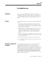
Preface
Introduction
Read this preface to become familiar with the organization of the
manual. In this preface, you will read about the following:
• Who Should Use this Manual
• Purpose of this Manual
• Contents of this Manual
• Related Documentation
• Conventions Used in this Manual
• Allen-Bradley Support
Who Should Use this
Manual
This manual is intended for qualified service personnel responsible for
setting up and servicing the Ultra5000™ drive with DeviceNet™. You
must have previous experience with and a basic understanding of
electrical terminology, programming procedures, networking,
required equipment and software, and safety precautions.
Purpose of this Manual
This manual is a reference guide for using DeviceNet to configure,
monitor, or control Ultra5000 drives with DeviceNet.
Publication 2098-RM002A-EN-P – October 2001
P-2
Preface
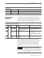
Contents of this Manual
This manual contains the following sections:
Chapter
Related Documentation
Publication 2098-RM002A-EN-P – October 2001
Title
Contents
Preface
An overview of this manual and
Allen-Bradley technical support.
1
The DeviceNet Interface
Describes how to install, connect and
commission an Ultra5000 with
DeviceNet.
2
DeviceNet Driver Installation
Describes loading of the drivers and
setup files for the Ultra5000 Drive with
DeviceNet.
3
DeviceNet Overview
Introduces DeviceNet parameters and
messaging
4
Programming Reference
Configuration data and behaviors
implemented in the Ultra5000 Drive
with DeviceNet are defined using object
modeling.
5
Troubleshooting DeviceNet
Drives
Describes troubleshooting actions for
DeviceNet interfaces to Ultra5000
drives.
These publications provide additional information specific to the
Ultra5000 Drive with DeviceNet or DeviceNet in general. To obtain a
copy, contact your local Rockwell Automation office or distributor.
For information about:
Read this document:
Publication Number
A glossary of industrial
automation terms and
abbreviations
Allen-Bradley Industrial
Automation Glossary
AG-7.1
How to commission a
DeviceNet system.
DeviceNet Cable System
Planning and Installation
Manual
DN-6.7.2
An overview of
Allen-Bradley motion
controls and systems
Motion Control Selection
Guide
GMC-SG001x-EN-P
How to use RSNetWorx™
RSNetWorx for DeviceNet
Getting Results Manual
9399-DNETGR
A description of the
Ultra3000™ and Ultra5000
drives
Ultra Family Brochure
2098-BR001x-EN-P
Preface
For information about:
Read this document:
Publication Number
How to install and
troubleshoot the Ultra5000
drive
Ultra5000 Intelligent
Positioning Drive
Installation Manual
2098-IN001x-EN-P
How to install Ultraware™
Ultraware CD Installation
Instructions
2098-IN002x-EN-P
Configuring the Ultra3000
DSD and Ultra5000 IPD
using Ultraware
Ultraware User Manual
2098-UM001x-EN-P
P-3
A copy of the DeviceNet Specification, Volumes I and II, Release 2.0
may be ordered from the web site http://www.odva.org of the Open
Device Vendor Association.
Conventions Used in this
Manual
The following conventions are used throughout this manual:
• Bulleted lists such as this one provide information, not procedural
steps
• Numbered lists provide sequential steps or hierarchical information
• Words you type or select appear in bold.
• When we refer you to another location, the section or chapter
name appears in italics
• Software commands and parameters are listed with initial capitals
and hardware signals are listed in all capitals (e.g., Jog Program
Velocity parameter, and ENABLE signal).
Publication 2098-RM002A-EN-P – October 2001
P-4
Preface
Allen-Bradley Support
Allen-Bradley offers support services worldwide, with over 75
sales/support offices, 512 authorized distributors and 260 authorized
systems integrators located throughout the United States alone, plus
Allen-Bradley representatives in every major country in the world.
Local Product Support
Contact your local Allen-Bradley representative for:
• Sales and order support
• Product technical training
• Warranty support
• Support service agreements
Technical Product Assistance
If you need to contact Allen-Bradley for technical assistance, please
review the information in this manual or that listed in Related
Documentation on page P-2 first. Then call your local Allen-Bradley
representative. For the quickest possible response, we recommend
that you have the catalog numbers of your products available when
you call.
Publication 2098-RM002A-EN-P – October 2001
Chapter
1
The DeviceNet Interface
Installing, Connecting, &
Commissioning Your
Ultra5000 with DeviceNet
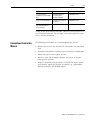
This manual serves as a reference for configuring, monitoring, and
controlling an Ultra5000 drive through a DeviceNet interface. The
following information is contained in this chapter.
• Wiring the DeviceNet connector.
• Setting drive addresses through the rotary switches.
• Configuring the data (baud) rate.
• Understanding the DeviceNet LED indicators.
Refer to the Ultra5000 Intelligent Positioning Drive Installation
Manual (2098-IN001x-EN-P) for additional information regarding
installation and troubleshooting of the main drive unit.
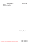
Figure 1.1
Ultra5000 DeviceNet External Connections
Module Status
Network Status
Data Rate Selector Switch
DeviceNet Connector
MSD Node Address Selector Switch
LSD Node Address Selector Switch
Publication 2098-RM002A-EN-P – October 2001
1-2
The DeviceNet Interface
DeviceNet Connector Pins and Signals (P2)
Pin
Description
Signal
1
Network Power Common 24V DC
V-
2
Network Communication Signal Line
Can_L
3
Shield
Shield
4
Network Communication Signal Line
Can_H
5
Network Power 24V DC
V+
Planning Your DeviceNet Network
A DeviceNet network is a planned arrangement of electrical power
and device distribution that is adjusted for optimal communications.
Before you add devices, record the following:
• Network data rate
• Network cable system map (topology) to which you are connecting
• Distances between cable system components
• Device current draw and voltage drop for each device on the
network
• Limitation of the trunk and drop cables
Refer to the table below for recommended trunk and drop lengths.
Data Rates
125 Kbps
250 Kbps
500 Kbps
meters
feet
meters
feet
meters
feet
Thick Trunk Lines
500
1640
250
820
100
328
Thin Trunk Lines
100
328
100
328
100
328
6
20
6
20
6
20
156
5120
78
256
39
128
Maximum Drop Length
Cumulative Drop Budget
Refer to the DeviceNet Cable System Planning and Installation
Manual (publication DN-6.7.2) for specific guidance in calculating
and attaching the Ultra5000 to a network.
Publication 2098-RM002A-EN-P – October 2001
The DeviceNet Interface
1-3
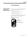
Connecting Your DeviceNet Cable
To attach a plugable, open style, screw-connector to the DeviceNet
cable:
1. Strip 65 mm (2.6 in.) to 75 mm (2.96 in.) of the outer jacket from
the end of the cable, leaving no more than 6.4mm (0.25 in.) of the
braided shield exposed.
Figure 1.2
Exposing the braided shield
6.4 mm
(0.25 in)
Outer Jacket
Braided Shield
2. Wrap the end of the cable with 38 mm (1.5 in.) of shrink wrap,
covering part of the exposed wires and part of the outer jacket.
Figure 1.3
Adding shrink wrap
Outer Jacket
38 mm
(1.5 in)
Shrink Wrap
3. Strip 8.1 mm (0.32 in.) of the insulation from the end of each of
the insulated wire.
Note: Be careful not to nick, cut, or otherwise damage the
individual strands of wire.
Trim the last 6.5 mm (0.26 in.) of the bare wires so that the outside
dimension does not exceed 0.17 mm (0.045 in.).
Figure 1.4
Exposing wire stands
8.1 mm
(0.32 in)
Outer Jacket
Shrink Wrap
Publication 2098-RM002A-EN-P – October 2001
1-4
The DeviceNet Interface
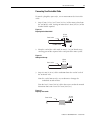
4. Insert each wire into the appropriate clamping cavity of the
plugable screw connector, according to the color of the cable
insulation.
5. Use an 1/8 inch flat blade screwdriver to attach wires in the
connector. Firmly tighten the clamping screws to secure each wire.
Plug Connector
1
2
3
4
5
3
2
1
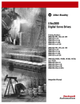
Figure 1.5
Wiring the DeviceNet connector
5
4
Red (V+)
White (Can_H)
Bare (Shield)
Blue (Can_L)
Black (V-)
Terminal Cable Color
Designation
1
Black
V-
2
Blue
Can_L
3
Bare
Shield
4
White
Can_H
5
Red
V+
6. Insert the connector on the Ultra5000 drive to attach the
DeviceNet network.
Publication 2098-RM002A-EN-P – October 2001
The DeviceNet Interface
Configuring Your Ultra5000
with DeviceNet
1-5
To configure your Ultra5000 drive with DeviceNet:
1. Verify that there is no power applied to the drive, and the
DeviceNet cable is connected (refer to figures 1.1 through 1.5 in
this chapter.
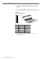
2. Set the node address for each drive in your system. Valid node
addresses are 00-63 and PGM. The MSD rotary switch, Figure 1.6,
sets the most significant digit and the LSD rotary switch sets the
least significant digit. For switch locations, refer to Figure 1.1 on
page 1-1 of this chapter. The following table provides examples.
For this Node
Address:
Set the MSD switch to:
Set the LSD switch to:
10
1
0
11
1
1
12
1
2
Figure 1.6
MSD and LSD Rotary Switches
Use the MSD and LSD rotary switches on the
DeviceNet panel of the drive to set node
addresses.
2
4
0
8
2
6
4
0
8
6
MSD
LSD
Note: Selecting an invalid node address (> 63) sets the node
address according to a non-volatile parameter stored in the
drive.
Refer to the Ultra5000 Intelligent Positioning Drive Installation
Manual (2098-IN001x-EN-P) for a listing of reserved node addresses.
3. Set the data rate switch, Figure 1.7, to the established DeviceNet
network data rate. Valid data rates are 125 kbps, 250 kbps, 500
kbps, AUTO, and PGM. Refer to Figure 1.1 on page 1-1 for the
switch location on the drive.
Note: Selecting AUTO automatically matches the device data rate
to the rate of the network. Selecting PGM sets the data rate
according to a non-volatile parameter stored in the drive.
Publication 2098-RM002A-EN-P – October 2001
1-6
The DeviceNet Interface
Figure 1.7
Data Rate Rotary Switch
Use the Data Rate rotary switch on the DeviceNet
panel of the drive to set the data rate.
4. Apply power to the drive.
5. Observe the module status LED.
If the module status LED:
Then:
Is not steady green
Refer to Troubleshooting DeviceNet Drives
on page 5-1.
Is steady green
The drive is ready. Go to step 6.
6. Observe the network status LED.
Publication 2098-RM002A-EN-P – October 2001
If the network status LED:
Then:
Is off
Establishing communication with
network (wait for flashing or
steady green).
Is not flashing or steady green
Refer to Troubleshooting
DeviceNet Drives on page 5-1.
Is flashing or steady green
Communication is ready. Go to
Chapter 2.
Chapter
2
DeviceNet Driver Installation
Follow the procedure listed in the Ultraware User Manual (publication
2098-UM001x-EN-P) to load and create the requisite DeviceNet drivers
for the Ultra5000 drive.
1. Install the following files as Drivers to the Ultra5000 drive:
• DNetLoad.exe
• DNetServ.exe
2. Load the following files to the Files branch of the Ultra5000 drive:
• DNetBoot.hex
• DNetMain.hex
3. Cycle power on the Ultra5000 and verify that within
approximately 15 seconds the green Module Status LED on the
DeviceNet interface is lit (on). This indicates successful installation
of the drivers. The Module Status LED will flash red-green while
the DeviceNet interface card is being initialized.
4. Select Rescan from the Tools menu. Verify the DNetServ.exe
automatically creates the following Global Variables in the
Workspace of the Ultra5000 drive.
Name
Type
Number of Elements
DNetConfigData
Long Int
8
DNetIntArray
Long Int
32
DNetFltArray
Float
32
IMPORTANT
If the Ultra5000 Drive Properties are Reset to Factory
Settings with Ultraware, the DeviceNet drivers are
erased and must be reinstalled.
Publication 2098-RM002A-EN-P – October 2001
2-2
DeviceNet Driver Installation
Configuring Ultra5000
DeviceNet Using the
DNetConfigData Array
The DNetConfigData array is the interface for configuring
DeviceNet on the Ultra5000. The array is a standard Ultra5000 long
integer array and is automatically created by the DeviceNet driver
program. For more information on arrays, see the Ultra5000
Programming Manual.
Array Index 0 – PGM MAC ID
The programmed non-volatile DeviceNet Node Address (MAC ID).
Value
Description
0 to 63
MAC ID range (default is 63)
Array Index 1 – PGM Baudrate
The programmed non-volatile DeviceNet Data Rate.
Value
Description
0
125 kps (default)
1
250 kps
2
500 kps
3
Autobaud
Array Index 2 – DeviceNet Module Fault Action
ATTENTION
!
Risk of severe bodily injury or equivalent damage
exists.
The Module Fault Action value allows you to change
the default configuration, and to potentially allow the
drive to continue to operate when communication
with the DeviceNet module is lost.
Determines the action the drive should take when it cannot
communicate with the DeviceNet module.
Publication 2098-RM002A-EN-P – October 2001
Value
Description
0
DeviceNet fault E14 (default)
1
Ignore
DeviceNet Driver Installation
2-3
Array Index 3 – DeviceNet Idle Fault Action
ATTENTION
!
Risk of severe bodily injury or equivalent damage
exists.
The Idle Fault Action value allows you to change the
default configuration, and to potentially allow the
drive to continue to operate when communication
with the DeviceNet module is lost.
Determines the action the drive should take if the master sends a zero
length I/O message to the drive, which may occur if a PLC (master) is
set to program mode. No action will be taken if I/O Receive Select is
set to 0 (No data consumed).
Value
Description
0
DeviceNet fault E14 (default)
1
Ignore
Array Index 4 – DeviceNet Comm Fault Action
ATTENTION
!
Risk of severe bodily injury or equivalent damage
exists.
The Comm Fault Action value allows you to change
the default configuration, and to potentially allow the
drive to continue to operate when communication
with the DeviceNet module is lost.
Determines the action the drive should take if the drive detects a
network failure while an I/O messaging connection is active.
Value
Description
0
DeviceNet fault E14 (default)
1
Ignore
Publication 2098-RM002A-EN-P – October 2001
2-4
DeviceNet Driver Installation
Array Index 5 – I/O Transmit Select
Selects the input (produced) assembly that is transmitted by the drive
over a Polled I/O Messaging Connection. If the value is modified, you
have to either close any existing I/O Messaging connection(s), power
cycle the drive, reset the drive, or remove and reapply DeviceNet
power for the drive to use the modified value.
Refer to Assembly Object, Instance ID = 1 - 16 on page 4-12 for
information on the data format.
Publication 2098-RM002A-EN-P – October 2001
Value
Description
0
No data produced.
1
One Integer:
DNetIntArray[0]
2
Two Integers:
DNetIntArray[0], DNetIntArray[1]
3
One Float:
DNetFltArray[0]
4
Two Floats:
DNetFltArray[0], DNetFltArray[1]
5
One Integer, One Float:
DNetIntArray[0], DNetFltArray[0]
6
Two Integers, One Float:
DNetIntArray[0], DNetIntArray[1], DNetFltArray[0]
7
One Integer, Two Floats:
DNetIntArray[0], DNetFltArray[0], DNetFltArray[1]
8
Two Integers, Two Floats:
DNetIntArray[0], DNetIntArray[1], DNetFltArray[0], DNetFltArray[1]
DeviceNet Driver Installation
2-5
Array Index 6 – I/O Receive Select
Selects the output (consumed) assembly that is updated when a
Polled I/O Message is received by the drive. If the value is modified,
you have to either close any existing I/O Messaging connection(s),
power cycle the drive, reset the drive, or remove and reapply
DeviceNet power for the drive to use the modified value.
Refer to Assembly Object, Instance ID = 1 - 16 on page 4-12 for
information on the data format.
Value
Description
0
No data consumed
1
One Integer:
DNetIntArray[2]
2
Two Integers:
DNetIntArray[2], DNetIntArray[3]
3
One Float:
DNetFltArray[2]
4
Two Floats:
DNetFltArray[2], DNetFltArray[3]
5
One Integer, One Float:
DNetIntArray[2], DNetFltArray[2]
6
Two Integers, One Float:
DNetIntArray[2], DNetIntArray[3], DNetFltArray[2]
7
One Integer, Two Floats:
DNetIntArray[2], DNetFltArray[2], DNetFltArray[3]
8
Two Integers, Two Floats:
DNetIntArray[2], DNetIntArray[3], DNetFltArray[2], DNetFltArray[3]
Array Index 7 – DeviceNet Modules Status
This is a read-only value that indicates the last modules fault status.
This value defaults to zero on power up and reset.
Value
Description
0
No Fault (default)
1
DeviceNet Idle Fault
2
DeviceNet Comm Fault
Publication 2098-RM002A-EN-P – October 2001
2-6
DeviceNet Driver Installation
Array Index 8 – DeviceNet Loader Version
This is a read-only value that indicates the current version of
DNetLoad.exe. The version number is displayed without periods (e.g.
version 1.2.0 will display as 120).
Array Index 9 – DeviceNet Server Version
This is a read-only value that indicates the current version of
DNetServ.exe. The version number is displayed without periods (e.g.
version 1.2.0 will display as 120).
Publication 2098-RM002A-EN-P – October 2001
Chapter
3
DeviceNet Overview
Introduction
DeviceNet is an open, global industry-standard communication
network. It is designed to provide an interface from a programmable
controller through a single cable directly to smart devices such as
sensors, push buttons, motor starters, simple operator interfaces and
drives.
Features
The Ultra5000 Drive with DeviceNet Interface provides the following
features:
• Ultra5000 Drive with DeviceNet implements the Unconnected
Message Manager (UCMM) which is used to establish a Group 3
Explicit Message connection. Up to five Group 3 Explicit Messaging
connections can be established.
• Faulted-node Recovery, allows the node address of a device to be
changed even when it is faulted on the network. This feature
requires the support of proper PC software tools and the Node
Address (0-63, PGM) switches be set to the PGM (program)
position.
• Software configuration lets you configure the Ultra5000 Drive with
DeviceNet using RSNetWorx for DeviceNet (3.00.01 or later, version
3.00 with Service Pack 1).
• Autobaud allows the drive to determine the network data rate.
Note: User programs and files cannot be loaded to the Ultra5000 drive
over DeviceNet.
Parameters and Electronic
Data Sheet
The Ultra5000 with DeviceNet contains a set of parameters that are
used to configure and monitor the drive. You can perform
configuration by changing the values associated with individual
parameters. Parameter values may be written and read via DeviceNet.
Writing a value to a parameter may configure drive operations such as
the acceleration or deceleration rates. Writing a value to a parameter
may also configure DeviceNet operations such as which input and
output assemblies are to be used for I/O communications with a
master (scanner). The parameter set is documented in Programming
Reference beginning on page 4-1.
Publication 2098-RM002A-EN-P – October 2001
3-2
DeviceNet Overview
Electronic Data Sheet (EDS) files are specially formatted ASCII files
that provide all of the information necessary for a configuration tool
such as RSNetworx for DeviceNet to access and alter the parameters
of a device. Information about each parameter is contained in the file
such as parameter min, max, and default values, parameter data
format and scaling, and the parameter name and units. You can create
or access an EDS file stored in the Ultra5000 Drive with DeviceNet via
RSNetworx for DeviceNet (3.00.01 or later, version 3.00 with Service
Pack 1) or download an EDS file for the Ultra5000 Drive with
DeviceNet from Rockwell Automation/Allen-Bradley web-site
www.ab.com/networks/eds.
DeviceNet Messaging
The Ultra5000 with DeviceNet operates as a slave device on a
DeviceNet network. The drive supports Explicit Messages and Polled
I/O Messages of the predefined master/slave connection set. The
drive also supports the Unconnected Message Manager (UCMM) so
that up to five Group 3 Explicit Message connections may be
established with the drive.
Predefined Master/Slave Connection Set
A set of messaging connections that facilitate communications and is
typically seen in a master/slave relationship is known as the
Predefined Master/Slave Connection set. The master is the device that
gathers and distributes I/O data for the process controller. A
DeviceNet master scans its slave devices based on a scan list it
contains. Each slave device returns I/O data to its master device.
The I/O data exchanged over this connection is pre-defined.
Explicit Response/Request Messages
Explicit Request messages are used to perform operations such as
reading and writing parameter values. Explicit Response messages
indicate the results of the attempt to service an Explicit Request
message.
Polled I/O Command/Response Messages
The Poll Command is an I/O message transmitted by the master
device. A Poll Command is directed toward a specific slave device. A
separate Poll Command must be sent to each slave device that is to be
Publication 2098-RM002A-EN-P – October 2001
DeviceNet Overview
3-3
polled. The Poll Response is the I/O message that the slave device
transmits back to the master device.
I/O Messaging and Explicit
Messaging with DeviceNet
You can configure and monitor the drive with either I/O Messaging or
Explicit Messaging. I/O messages are for time-critical, control-oriented
data. I/O messages typically are used for moving predefined data
repeatedly with minimum protocol overhead. Explicit Messages
provide multi-purpose, point-to-point communication paths between
two devices. Explicit Messaging typically would not be used to
exchange data periodically since I/O Messages have a higher priority
and lower protocol overhead than Explicit Messages. However,
Explicit Messages have more flexibility by specifying a service to be
performed and a specific address.
Selecting Input and Output
Assemblies for I/O
Messages
The Ultra5000 with DeviceNet provides sixteen generic Input and
Output Assemblies. The choice of which Input and/or Output
Assembly to use should be based on the type of information that is
appropriate in the particular system. The I/O Assemblies are mapped
to the first four 32-bit values of the Long Integer (DNetIntArray) and
Floating-point (DNetFltArray) arrays
The Ultra5000 has no pre-defined information stored in these
locations. The contents of the locations are under user program
control, and it is the responsibility of the user program(s) to update
and utilize the values as necessary.
The choice of which Input and Output Assembly to use should be
based on what sort of information is appropriate in a particular
system. You should keep in mind that larger assemblies utilize more
network bandwidth. Information on the data format of all the
Assemblies is given in Assembly Object (Class ID 04H) on page 4-11.
Publication 2098-RM002A-EN-P – October 2001
3-4
DeviceNet Overview
Publication 2098-RM002A-EN-P – October 2001
Chapter
4
Programming Reference
The Ultra5000 Drive with DeviceNet implements a vendor specific
device profile - Rockwell Automation Miscellaneous (Device Type:
73hex).
The configuration data and behaviors implemented in the Ultra5000
Drive with DeviceNet are defined using object modeling. The
Ultra5000 Drive with DeviceNet is modeled as a collection of objects.
An Object is a collection of related attributes and services. An attribute
is an externally visible characteristic or feature of an object, while a
service is a procedure an object can perform.
The following general definitions also may be useful in understanding
DeviceNet object modeling:
• Object - A representation of a particular type of data component
within the DeviceNet node.
• Instance - A specific occurrence of an Object.
• Attribute - A description of a characteristic or feature of an Object.
Attributes provide status information or govern the operation of an
Object.
• Service - A function performed by an Object.
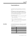
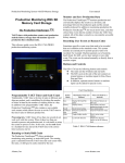
Object Model
The Object Model diagram on Page 4-2 depicts the objects supported
in the Ultra5000 Drive with DeviceNet. The following table indicates
the object classes present in this device, and the number of instances
present in each class.
Object Class
Number of Instances
Identity
4
Message Router
1
DeviceNet
1
Assembly
16
Connection
1 - I/O
6 - Explicit
Parameter
340
Publication 2098-RM002A-EN-P – October 2001
4-2
Programming Reference
Figure 4.1
Object Model
DeviceNet Network
DeviceNet
Node
05H
Connection
Object
Assembly
Object
Class ID #5
0X05
Message
Router
04H
Class ID #4
0X04
02H
Class ID #2
0X02
Identity
Object
01 H
Class ID #1
0X01
03H
DeviceNet
Object
Application
Object
Ultra5000
(no public
Interface)
Parameter
Object
0FH
Class ID #15
0X0F
Class ID #3
0X03
How Objects Affect Behavior
The objects in the Ultra5000 Drive with DeviceNet affect its behavior
as shown in the table below.
Publication 2098-RM002A-EN-P – October 2001
Object
Effect on Behavior
Message Router
No effect
DeviceNet
Configures port attributes (node address, data rate, and BOI)
Assembly
Defines I/O data format
Connection
Contains the number of logical ports into or out of the device
Parameter
Provides a public interface to the device configuration data
Programming Reference
4-3
The Defined Object Interface
The objects in the Ultra5000 Drive with DeviceNet have the interface
listed in the following table.
Object
Interface
Message Router
Explicit Messaging Connection Instance
DeviceNet
Message Router
Assembly
I/O Connection or Message Router
Connection
Message Router
Parameter
Message Router
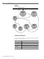
Object Addressing
The Media Access Control Identifier (MAC ID) is the common basis for
logically addressing separate physical components across DeviceNet.
The MAC ID is a unique integer assigned to each DeviceNet node that
distinguishes it specifically from among other nodes on the same
network. The MAC ID often is referred to as the node address. Each
component (object) is further identified with the following address
components:
Component
Description
Class ID
The Class ID is a unique integer value assigned to each Object Class
accessible from the network. The Ultra5000 supports an 8-bit Class ID.
Instance ID
The Instance ID is a unique identification assigned to an Object Instance
that identifies it among all Instances of the same Class.
It is also possible to address the Class itself by utilizing the Instance ID
value zero (0). The Ultra5000 supports an 16-bit Instance ID.
Attribute ID
The Attribute ID is a unique identification assigned to a Class Attribute
and/or Instance Attribute.
Publication 2098-RM002A-EN-P – October 2001
4-4
Programming Reference
Figure 4.2
Node Objects
DeviceNet Node 1
DeviceNet Node 2
MAC ID #1
MAC ID #2
MAC ID #4:
Object Class #5
Instance #2
Attribute #1
DeviceNet Network
DeviceNet Node 3
DeviceNet Node 4
Object
Class #5
Attribute #1
Attribute #2
Instance
#2
Instance
#1
MAC ID #3
Instance
#1
Object
Class #3
Instance
#1
Object
Class #5
MAC ID #4
Data Type Definitions
Publication 2098-RM002A-EN-P – October 2001
The following mnemonics define the Ultra5000 with DeviceNet data
types.
Mnemonic
Description
ARRAY
Sequence of Data
BOOL
Boolean (1 byte)
BYTE
Bit String (1 byte)
DINT
Signed Double Integer (4 bytes)
DWORD
Bit String (4 bytes)
EPATH
DeviceNet Path Segments
INT
Signed Integer (2 bytes)
REAL
Floating Point (4 bytes)
SHORT_STRING
Character String
(1 byte length indicator, 1 byte per character)
SINT
Signed Short Integer (1 byte)
UDINT
Unsigned Double Integer (4 bytes)
Programming Reference
Identity Object
(Class ID 01 )
Mnemonic
Description
UINT
Unsigned Integer (2 bytes)
USINT
Unsigned Short Integer (1 byte)
WORD
Bit String (2 bytes)
4-5
This object provides identification and general information about the
device. The interface card implements four Identity Objects.
H
Identity Object,
Attribute for Instance ID = 0 (Class Attributes)
Attr Access Attribute
ID Rule
Name
2
Get
Type Description
Max Instance UINT Maximum instance
number of an object
currently created in
this class level of the
device.
Semantics
of Values
The largest instance
number of a created
object at this class
hierarchy level.
Identity Object,
Instance ID = 1 - 4
Instance ID
Description
1
Adapter Main Firmware
2
Ultra5000 Main Firmware
3
Adapter Boot Firmware
4
Ultra5000 Boot Firmware
Publication 2098-RM002A-EN-P – October 2001
4-6
Programming Reference
Identity Object,
Attributes of Instance ID 1
Attr. Access Attribute
ID
Rule
Name
Data
Type
Description
Semantics
of Values
1
UINT
Identification of
each vendor by
number
01 = Rockwell
Automation/
Allen-Bradley
Indication of
general type of
product.
Instance 1:
115 = Rockwell
Automation
Miscellaneous
2
Get
Vendor ID
Device Type
Instances 2-4:
105 = Subcomponent
3
Identification of a Instance 1:
particular product 64 = 2098-IPD-005-DN
of an individual
65 = 2098-IPD-010-DN
vendor
66 = 2098-IPD-020-DN
102 = 2098-IPD-030-DN
103 = 2098-IPD-075-DN
104 = 2098-IPD-150-DN
105 = 2098-IPD-HV030-DN
106 = 2098-IPD-HV050-DN
107 = 2098-IPD-HV100-DN
108 = 2098-IPD-HV150-DN
109 = 2098-IPD-HV220-DN
Product code
Instances 2-4:
01 = Firmware
Major
Minor
STRUCT
of:
USINT
USINT
Revision of the
item the Identity
Object
represents.
5
Status
WORD
This attribute
represents the
current status of
the entire device.
Its value changes
as the state of
the device
changes.
See table: Identity
Object, Status
Description of Attribute
ID 5
6
Serial Number UDINT
Serial number of
device
Unique identifier for each
device.
7
Product Name SHORT_ Readable
STRING identification
4
Revision
Major Revision
Minor Revision
Unique identifier for each
product.
Identity Object,
Status Description of Attribute ID 5
Bit (s)
Description
Semantics of Values
0
Owned
TRUE = device has an owner
1
2
Publication 2098-RM002A-EN-P – October 2001
Reserved, set to 0
Configured
Always = 0
Programming Reference
4-7
Identity Object,
Status Description of Attribute ID 5 (Continued)
Bit (s)
Description
Semantics of Values
3
Reserved, set to 0
4, 5, 6, 7
Vendor specific
8
Minor recoverable
fault
Always = 0
9
Minor unrecoverable
fault
Always = 0
10
Major recoverable
fault
TRUE if self diagnosis detects a major fault
11
Major unrecoverable
fault
Always = 0
12, 13
Reserved, set to 0
14, 15
Identity Object,
Common Services
Service
Code
Implemented for
Class
Instance
0EH
Yes
Yes
05H
No
11H
Yes
n/a
Service
Name
Service
Description
Get_Attribute_Single
Returns the contents of the
specified attribute.
Reset
Invokes the Reset service for
the device.
Find_Next_Object_
Instance
Causes the specified class to
search and return a list of
instance IDs of existing
instances of the Identity
Object.
Reset Service
When the Identity Object receives a Reset request, it:
• determines if it can perform the reset
• responds to the request
• attempts to perform the reset
Publication 2098-RM002A-EN-P – October 2001
4-8
Programming Reference
The Reset common service has the following object-specific
parameter:
Identity Object,
Reset Service
Message Router Object
(Class ID 02 )
H
Name
Data
Type
Description
Semantics
of Values
Type
USINT
Type of Reset
0 = Emulate as closely as possible cycling power of
the drive. (default)
1 = Emulate cycling power as closely as possible.
The drive can not be returned to out-of-box
configuration without deletion of DeviceNet drivers
and files.
The Message Router Object provides a messaging connection point
through which a Client may address a service to any object class or
instance residing in the physical device.
Message Router Object,
Attributes of Instance ID = 1
Attr. Access Attribute
ID
Rule
Name
Data
Type
Description
Semantics
of Values
2
UINT
Maximum number
of connections
supported
Count of the max
number of
connections
supported
Current count of
the number of
connections
allocated to
system
communication
Get
Number Available
3
Number active
Number of
connections
currently used by
system
components
4
Active connections ARRAY
of
UINT
Array of system
A list of the
connection IDs
connection IDs of
the currently active
connections
Message Router Object,
Common Services
Publication 2098-RM002A-EN-P – October 2001
Service
Code
Service
Name
Service
Description
0EH
Get_Attribute_Single Returns the contents of the specified attribute
4-9
Programming Reference
DeviceNet Object
(Class ID 03 )
The DeviceNet Object provides configuration and status attributes of a
DeviceNet port.
H
DeviceNet Object,
Attribute of Instance ID = 0 (Class Attribute)
Attr. ID Access Attribute
Rule
Name
Data Description
Type
Semantics
of Values
1
UINT Revision of the DeviceNet Object
Class definition upon which the
implementation is based.
=2
Get
Revision
DeviceNet Object,
Attributes of Instance ID = 1
Attr. Access
ID
Rule
Attribute
Name
Data Type
Description
Semantics
of Values
1
MAC ID
USINT
Node Address
Range 0-63
Set
Set is only supported if the MAC ID is programmable.
Refer to Ultra5000 Intelligent Positioning Drive Installation Manual listed on page P-3
for Rotary DIP switch data setting.
2
Set
Baud Rate
Data Rate
0 = 125K,
1 = 250K,
2 = 500K
Set is only supported if the data rate is programmable.
Refer to Ultra5000 Intelligent Positioning Drive Installation Manual for Rotary DIP
switch data setting.
3
4
Set
Bus OFF
Interrupt
(BOI)
BOOL
Bus-OFF Interrupt Default = 0
Bus OFF
Counter
USINT
Number of times
Controller Area
Network (CAN)
went to the
bus-OFF state
Range 0-255
Publication 2098-RM002A-EN-P – October 2001
4-10
Programming Reference
DeviceNet Object,
Attributes of Instance ID = 1 (Continued)
Attr. Access
ID
Rule
Attribute
Name
5
Allocation STRUCT of:
information BYTE
Get
Data Type
USINT
Description
Semantics
of Values
Allocation choice
(1 byte)
Refer to the
DeviceNet Object
definition in the
DeviceNet
Specification.
+ Master MAC
ID (1 byte)
Range 0-63, 255
Modified via
Allocate only.
6
MAC ID
Switch
Changed
7
Baud Rate
Switch
Changed
8
MAC ID
Switch
Value
9
Baud Rate
Switch
Value
BOOL
USINT
The Node
Address
switch(es) have
changed since
last power-up/
reset.
0 = No change
1 = Change since
last reset or
power-up
The Baud Rate
switch(es) have
changed since
last power-up/
reset.
0 = No change
1 = Change since
last reset or
power-up
Actual value of
Node Address
switch(es).
Range 0-63
Range 0-2
Actual value of
Baud Rate
switch(es), or
operating value
after an autobaud
was completed.
DeviceNet Object,
Common Services
Publication 2098-RM002A-EN-P – October 2001
Service
Code
Service
Name
Service
Description
0EH
Get_Attribute_Single
Returns the contents of the
specified attribute.
10H
Set_Attribute_Single
Modifies the specified attribute.
Programming Reference
4-11
DeviceNet Object,
Class Specific Services
Assembly Object
(Class ID 04 )
H
Service
Code
Service
Name
Service
Description
4BH
Allocate_Master/Slave_
Connection_Set
Requests the use of the Predefined
Master/Slave Connection Set.
4CH
Release_Group_2_
Identifier_Set
Indicates that the specified
Connections within the Predefined
Master/Slave Connection Set are
no longer desired. These
connections are to be released
(deleted).
The Ultra5000 with DeviceNet uses Assembly Objects to send generic
data to and from a Master (scanner) device over an I/O connection.
The terms Input and Output are defined from the scanner's point of
view:
• Output Assemblies are defined as the information that is output by
the scanner and consumed by the Ultra5000.
• Input Assemblies are consumed by the scanner or are the scanner's
input.
The Ultra5000 with DeviceNet allows you to choose between various
Input and Output Assemblies, thereby choosing the data format of the
messages that are passed back and forth between the Ultra5000 with
DeviceNet and the scanner over the I/O connection. The following
parameters select the Assembly Object instances that are exchanged
over an I/O messaging connection.
Parameter Parameter Name
Instance 1
Description
8
I/O Receive Select
Selects the Assembly Object instance that is
updated when a Polled I/O message is received
by the drive. See page 4-19 for more information.
9
I/O Transmit (Xmit)
Select
Selects the Assembly Object instance that is
transmitted by the drive over a Polled I/O
connection. See page 4-19 for more information.
1
Refer to the section on the Parameter Object for more information about parameter instances.
IMPORTANT
If the above parameters are modified, you must
perform one of the following before the modified
value(s) are active:
•Close any existing I/O messaging connection.
•Power cycle the drive.
•Remove and reapply DeviceNet power to the drive.
•Reset the drive.
Publication 2098-RM002A-EN-P – October 2001
4-12
Programming Reference
The following Assembly Objects are implemented in the drive and
buffer I/O in the following fashion:
• RO = Read Only
• R/W = Read/Write Protected.
Assembly Object,
Instance ID = 1 - 16
ID
Data Type
1
Access
Size
(Bytes)
Description 1
Static Output R/W
4
One Integer:
DNetIntArray[2]
2
Static Output R/W
8
Two Integers:
DNetIntArray[2], DNetIntArray[3]
3
Static Output R/W
4
One Float:
DNetFltArray[2]
4
Static Output R/W
8
Two Floats:
DNetFltArray[2], DNetFltArray[3]
5
Static Output R/W
8
One Integer, One Float:
DNetIntArray[2], DNetFltArray[2]
6
Static Output R/W
12
Two Integers, One Float:
DNetIntArray[2], DNetIntArray[3],
DNetFltArray[2]
7
Static Output R/W
12
One Integer, Two Floats:
DNetIntArray[2], DNetFltArray[2],
DNetFltArray[3]
8
Static Output R/W
16
Two Integers, Two Floats:
DNetIntArray[2], DNetIntArray[3],
DNetFltArray[2], DNetFltArray[3]
9
Static Input
RO
4
One Integer:
DNetIntArray[0]
10
Static Input
RO
8
Two Integers:
DNetIntArray[0], DNetIntArray[1]
11
Static Input
RO
4
One Float:
DNetFltArray[0]
12
Static Input
RO
8
Two Floats:
DNetFltArray[0], DNetFltArray[1]
13
Static Input
RO
8
One Integer, One Float:
DNetIntArray[0], DNetFltArray[0]
14
Static Input
RO
12
Two Integers, One Float:
DNetIntArray[0], DNetIntArray[1],
DNetFltArray[0]
15
Static Input
RO
12
One Integer, Two Floats:
DNetIntArray[0], DNetFltArray[0],
DNetFltArray[1]
16
Static Input
RO
16
Two Integers, Two Floats:
DNetIntArray[0], DNetIntArray[1],
DNetFltArray[0], DNetFltArray[1]
1 The arrays are automatically saved in non-volatile storage.
Publication 2098-RM002A-EN-P – October 2001
Programming Reference
4-13
Assembly Object,
Attribute of Instances ID 1 - 16
Attr ID
Access
Rule
Attribute
Name
Data Type
3
Set
Data
ARRAY
Assembly Object,
Common Services
Service
Code
Implemented for
Class
Instance
0EH
Yes
Yes
10EH
No
Service
Name
Service
Description
Get_Attribute_Single
Returns the contents of the
specified attribute.
Set_Attribute_Single
Modifies an attribute value.
Publication 2098-RM002A-EN-P – October 2001
4-14
Programming Reference
DeviceNet Comm Fault Action
The Ultra5000 with DeviceNet will fault depending on the Comm
Fault Action setting if the Output (command) Assembly is not
periodically updated after the Output Assembly has been written to.
You can configure the Ultra5000 with DeviceNet to perform a Comm
Fault Action if the Output Assembly is not periodically updated after
the I/O (or explicit) messaging connection has been established.
Possible reasons the Output Assembly may not be updated in this way
include the following:
• The messaging connection is closed
• The DeviceNet cable is unplugged
ATTENTION
!
Risk of severe bodily injury or equivalent damage
exists.
The Comm Fault Action value allows you to change
the default configuration, and to potentially allow the
drive to continue to operate when communication
with the DeviceNet Module is lost.
By default, the Ultra5000 drive with DeviceNet will fault and disable
the drive when a DeviceNet Comm Fault is triggered. However, you
can configure the drive to ignore the DeviceNet Comm Fault by
setting the Ultra5000 DNetConfigData Array Index 4 – DeviceNet
Comm Fault Action to 1 (Ignore).
DeviceNet Idle Fault Action
The Ultra5000 with DeviceNet will fault depending on the Idle Fault
Action setting if the Master (scanner) sends I/O idle messages
(zero-length messages) and the drive expects non-zero length I/O
messages.
ATTENTION
!
Risk of severe bodily injury or equivalent damage
exists.
The Idle Fault Action value allows you to change the
default configuration, and to potentially allow the
drive to continue to operate when communication
with the DeviceNet Module is lost.
By default, the Ultra5000 drive with DeviceNet will fault and disable
the drive when an Idle Fault is triggered. However , no action will be
taken if the Ultra5000 DNetConfigData Array Index 6 – I/O Receive
Publication 2098-RM002A-EN-P – October 2001
Programming Reference
4-15
Select, Parameter 8 is set to 0 (No data consumed), or if you configure
the drive to ignore Array Index 3 – DeviceNet Idle Fault Action by
setting the DNetConfigData array to 1 (Ignore).
Using Explicit Messaging to Control the Ultra5000
Explicit messages provide multi-purpose, point-to-point
communication paths between two devices. It is possible to control
the drive through explicit messaging on DeviceNet by following
particular guidelines and by writing to various Assembly Objects that
are buffering the I/O data. Although it is possible to control the drive
by writing to various parameter objects, you should consider using a
user program interfacing with the Assembly Objects for controlling the
drive. The guidelines are as follows:
• Write to the various Assembly Objects that are buffering the I/O
data.
• Write access to any Assembly Object is not allowed if the message
is passed through a connection whose expected packet rate (EPR)
is zero or if I/O data is being sent over an I/O messaging
connection.
• The drive marks any explicit connection after allowing a write to
an Assembly Object through the connection.
• If a marked explicit connection times out based on the EPR, then
the fault action will be that for Communication Loss over the I/O
connection, using Array Index 4 – DeviceNet Comm Fault Action of
the DNetConfigData array.
• If a marked explicit connection is deleted, then the fault action will
be that configured for Idle over the I/O connection, using Array
Index 3 – DeviceNet Idle Fault Action of the DNetConfigData array.
• Multiple explicit connections can write/overwrite the control I/O if
they meet the guidelines specified. Each connection will be
marked individually within the drive.
• If the drive gets allocated/re-allocated by a controller such that
valid I/O data is being sent to the drive, or if an Idle condition
from the allocating controller is transitioned back to valid data,
then all marked explicit connections will be reset to unmarked and
future writes blocked.
• If a marked connection has its EPR value reset to zero (0) after
being marked, then the connection will become unmarked.
Publication 2098-RM002A-EN-P – October 2001
4-16
Programming Reference
Connection Object
(Class ID 05 )
H
The Connection Object manages the internal resources associated
with both I/O and Explicit Messaging Connections. The specific
instance generated by the Connection Class is referred to as a
Connection Instance or a Connection Object. A Connection Object
within a particular module actually represents one of the end-points of
a connection.
DeviceNet Connection Object,
Instance ID = 1 - 10
Instance Instances
ID
1
Group 2 Explicit Message Connection
2
Poll I/O Connection
6-10
Group 3 Explicit Message Connections
DeviceNet Connection Object,
Attributes of Instances ID = 1 - 10 /
Attr ID
1
Access Attribute
Rule
Name
Data Type
Description
Get
USINT
State of the Connection
State
2
Instance Type
3
Transport_class_trigger
BYTE
Defines the behavior of the Connection
4
Produced_connection_id
UINT
CAN identifier to transmit on
5
Consumed_connection_id
6
Initial_comm_characteristics
BYTE
Defines the Message Group(s) associated with
this Connection
7
Produced_connection_size
UINT
Maximum number of bytes transmitted across
this Connection
8
Consumed_connection_size
Maximum number of bytes received across this
Connection
Expected_packet_rate
Defines timing associated with this Connection
9
Set
12
I/O or Message Connection
CAN identifier to receive on
Watchdog_timeout_action
USINT
Defines how to handle Inactivity/Watchdog
timeouts
Produced_connection_path_
length
UINT
Number of bytes in the
produced_connection_path attribute
14
Produced_connection_path
EPATH
Specifies the Application Object whose data is
to be produced by this Connection object
15
Consumed_connection_path_length
UINT
Number of bytes in the
Consumed_connection_path attribute
16
Consumed_connection_path
EPATH
Specifies the Application Object(s) that are to
receive the data consumed by this Connection
Production_inhibit_time
UINT
Defines minimum time between new data
production for COS connections.
13
17
Get
Set
Publication 2098-RM002A-EN-P – October 2001
Programming Reference
4-17
DeviceNet Connection Object,
Common Services
Service Code
Service Name
Service Description
0EH
Get_Attribute_Single
Returns the contents of the specified attribute.
10H
Set_Attribute_Single
Modifies the specified attribute.
05H
Reset
Used to reset the Inactivity/Watchdog Timer associated with a Connection Object
Parameter Object
(Class ID 0F )
H
The DeviceNet Parameter Object provides the interface to the
Ultra5000 Drive with DeviceNet configuration data. It supplies a full
description of the parameter, including its minimum and maximum
values and a readable text string describing the parameter. The
instances start at one and increment with no gaps.
Parameter Object,
Attributes for Instance ID = 0 (Class Attributes)
Attr ID Access
Rule
Name
Data
Type
Description
Semantics of Values
1
Revision
UINT
Revision of this object
Current value = 01
Maximum instance number of an
object currently created in this class
level of the device
The largest instance number of a created
object at this class hierarchy level
Get
2
Max Instances
8
Parameter Class
Descriptor
WORD
Bit field that describe parameters
Bit 0 = supports parameter instances
Bit 1 = full attributes
Bit 2 = nonvolatile storage save command
Bit 3 = params are stored in nonvolatile
storage
9
Configuration
Assembly
Instance
UINT
Instance number of the configuration
assembly
0 = configuration assembly not supported
The table Parameter Instance on page 4-18 lists the parameter
instances implemented in the Ultra5000 Drive with DeviceNet. The
table Parameter Object Instance Attributes on page 4-49 lists the
instance attributes of the parameter object. A parameter value is
accessed via Attribute 1 of a parameter instance. Additional
information about the parameter object is located beginning on
Page 4-51.
IMPORTANT
Some parameters can not be modified while the
Ultra5000 Drive with DeviceNet is enabled. The drive
returns the error code, 10h - Device State Conflict, if
you attempt to modify one of these parameters while
the drive is enabled.
Publication 2098-RM002A-EN-P – October 2001
4-18
Programming Reference
Note: The Set_Attribute_Single service saves parameter values to RAM,
but not to non-volatile storage. To transfer parameter values
from RAM to non-volatile storage, perform one of the following:
• Perform the Save service on the Parameter Object.
• Write the value Execute Command (1) to Parameter 13 - Save
Parameter Values.
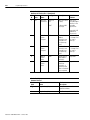
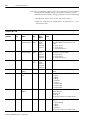
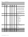
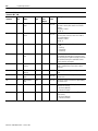
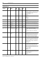
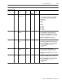
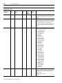
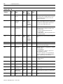
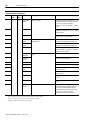
Parameter Object,
Instances ID 1- 340
Data
Size
(Bytes)
Description
Access
Rule
Parameter
Name
1
Get
DNet Main
SHORT_S 1 byte
Firmware Version TRING
length
indicator,
1 byte per
character
The version of the main firmware in the
DeviceNet adapter. The format is XX.YY.ZZ,
where:
XX = major revision
YY = minor revision
ZZ = maintenance revision
2
Get
DNet Boot
SHORT_S 1 byte
Firmware Version TRING
length
indicator,
1 byte per
character
The version of the boot firmware in the adapter.
The format is XX.YY.ZZ, where:
XX = major revision
YY = minor revision
ZZ = maintenance revision
3
Get
Drive Model
SHORT_S 1 byte
TRING
length
indicator,
1 byte per
character
The model number of the drive.
4
Get
DN-SW Node
Address
USINT
1
DeviceNet Node Address (Mac_ID) switch
setting.
5
Get
DN-SW Data
Rate
USINT
1
DeviceNet Data Rate switch setting.
0 = 125 kps
1 = 250 kps
2 = 500 kps
3 = Autobaud
4 = Program
5 = Programmable
6 = Programmable
7 = Programmable
6
Set
DN-NV Node
Address
USINT
1
The programmed nonvolatile DeviceNet Node
Address (Mac_ID).
Range: 0 to 63
Default: 63
Automatically saved in non-volatile storage.
7
Set
DN-NV Data Rate USINT
1
The programmed nonvolatile DeviceNet Data
Rate.
0 = 125 kps (default)
1 = 250 kps
2 = 500 kps
3 = Autobaud
Automatically saved in non-volatile storage.
Publication 2098-RM002A-EN-P – October 2001
Data
Type
Units /
Scale
Parameter
Instance
Programming Reference
4-19
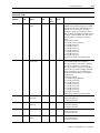
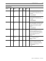
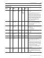
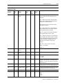
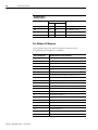
Parameter Object,
Instances ID 1- 340
Units /
Scale
Description
Parameter
Instance
Access
Rule
Parameter
Name
Data
Type
Data
Size
(Bytes)
8
Set
I/O Receive
Select
USINT
1
Selects the output (consumed) assembly that is
updated when a polled I/O message is received
by the drive. If the value is modified, the user has
to either, close any existing I/O messaging
connection(s), power cycle the drive, reset the
drive, or remove and reapply DeviceNet power for
the drive to use the modified value. Refer to the
Assembly Object for information on the data
format.
0 = No Data Consumed
1 = Assembly Instance 1 (default)
2 = Assembly Instance 2
3 = Assembly Instance 3
4 = Assembly Instance 4
5 = Assembly Instance 5
6 = Assembly Instance 6
7 = Assembly Instance 7
8 = Assembly Instance 8
Automatically saved in non-volatile storage.
9
Set
I/O Transmit
(Xmit) Select
USINT
1
Selects the input (produced) assembly that is
transmitted by the drive over a polled I/O
messaging connection. If the value is modified,
the user has to either, close any existing I/O
messaging connection(s), power cycle the drive,
reset the drive, or remove and reapply DeviceNet
power for the drive to use the modified value.
Refer to the Assembly Object for information on
the data format.
0 = No Data Produced
1 = Assembly Instance 9 (default)
2 = Assembly Instance 10
3 = Assembly Instance 11
4 = Assembly Instance 12
5 = Assembly Instance 13
6 = Assembly Instance 14
7 = Assembly Instance 15
8 = Assembly Instance 16
Automatically saved in non-volatile storage.
10
Set
Axis Enable
Command
USINT
1
Enable the drive.
0 = No Action (default)
1 = Execute Command
11
Set
Disable Axis
Command
USINT
1
Disable the drive.
0 = No Action (default)
1 = Execute Command
12
Set
Reset Drive
USINT
1
Reset the drive.
0 = No Action (default)
1 = Execute Command
13
Set
Save Parameter
Values
USINT
1
Save parameters in non-volatile storage.
0 = No Action (default)
1 = Execute Command
Publication 2098-RM002A-EN-P – October 2001
4-20
Programming Reference
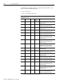
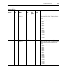
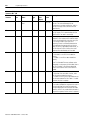
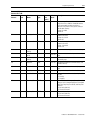
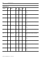
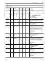
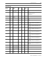
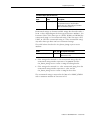
Parameter Object,
Instances ID 1- 340
Parameter
Instance
Access
Rule
Parameter
Name
Data
Type
Data
Size
(Bytes)
14
Set
Control Digital
Type
USINT
1
Units /
Scale
Description
Select a digital I/O type:
0 = Sourcing: Digital Inputs should be connected
to a 24 volt power supply, so current flows into
the drive when the input is ON. Digital Outputs
should be connected to ground, so current flows
from the drive when the output is ON. (default)
1 = Sinking: Digital Inputs should be connected to
ground, so current flows from the drive when the
input is ON. Digital Outputs should be connected
to a 24 volt power supply, so current flows into
the drive when the output is ON.
15
Get
Axis State
USINT
1
Indicates if the axis is enabled or disabled.
0 = Disabled
1 = Enabled
16
Get
Controller Fault
USINT
1
Provides the fault status of the drive.
0 = No Fault
4 = Motor Overtemperature
5 = IPM Fault
9 = Bus Undervoltage
10 = Bus Overvoltage
11 = Bad (Illegal) Hall State
14 = Network Communication
17 = User Current
18 = Overspeed
19 = Position (Following) Error
20 = Motor Encoder Error
21 = Auxiliary Encoder Error
22 = Motor Filter
23 = IPM Filter
24 = Velocity Error
26 = User Velocity
58 = Excess CPU Load
17
Get
Controller State
USINT
1
Provides the state of the controller.
0 = Idle
1 = Running
2 = Erasing
3 = Programming
4 = FlashFault
18
Get
Average Current
REAL
4
Amps
Average current.
19
Get
Torque Command REAL
4
Amps
Torque command.
20
Get
Torque Feedback
REAL
4
Amps
Torque feedback.
21
Get
Torque Error
REAL
4
Amps
Torque error.
Publication 2098-RM002A-EN-P – October 2001
Programming Reference
4-21
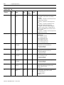
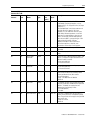
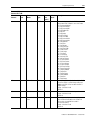
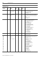
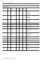
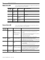
Parameter Object,
Instances ID 1- 340
Units /
Scale
Description
Parameter
Instance
Access
Rule
Parameter
Name
Data
Type
Data
Size
(Bytes)
22
Set
Enable Position
Limit
USINT
1
Enables the position limits. This causes the drive
to start monitoring the position limits. The
Position Limit State - Parameter 34 will transition
to “Running”.
0 = No Action (default)
1 = Execute Command
23
Set
Disable Position
Limit
USINT
1
Disables the position limits. This causes the drive
to stop monitoring the position limits. The
Position Limit State - Parameter 34 will transition
to “Disabled”.
0 = No Action (default)
1 = Execute Command
24
Set
Reset Position
Limit
USINT
1
After a position limit violation, the position limits
will go to the “Stopped” state. The drive will not
allow commanded motion in this state. Pressing
this button will allow the drive to respond to
commanded motion to back off of the limit
condition.
0 = No Action (default)
1 = Execute Command
25
Set
Position Limit
Decel
REAL
4
cnts/ sec2
When a limit is detected, the drive will use this
deceleration rate to bring the axis to a stop,
unless doing so would violate the Position Limit
Distance - Parameter 26. If necessary to stay
within the Position Limit Distance, the drive will
calculate a greater deceleration rate.
Range: 0 to 3.4e10
Default: 0
26
Set
Position Limit
Distance
DINT
4
cnts
When a limit is detected, the drive will bring the
axis to a stop within this distance.
Range: 0 to 2147483647
Default: 0
27
Set
Position Soft
Limits
USINT
1
Enables or disables detection of soft limit
violations. The Position Limits (see Enable
Position Limit - Parameter 22) must also be
enabled for soft limit violations to be detected.
Not saved in non-volatile memory.
0 = Disable (default)
1 = Enable
Publication 2098-RM002A-EN-P – October 2001
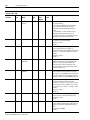
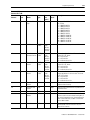
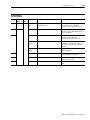
4-22
Programming Reference
Parameter Object,
Instances ID 1- 340
Units /
Scale
Description
Parameter
Instance
Access
Rule
Parameter
Name
Data
Type
Data
Size
(Bytes)
28
Set
Position Hard
Limits
USINT
1
Enables or disables detection of hard limit
violations. The Position Limits (see Enable
Position Limit - Parameter 22) must also be
enabled for hard limit violations to be detected.
The inputs to use for positive and negative hard
limits must be set (see Parameters 32 and 33
below) for the hard limits to be detected. Not
saved in non-volatile memory.
0 = Disable (default)
1 = Enable
Note: Hard limits are enabled on power-up if
either hard limit is assigned.
29
Set
Position Motor
Limits
USINT
1
Enables or disables detection of motor integral
limit violations. The Position Limits (see Enable
Position Limit - Parameter 22) must also be
enabled for motor limit violations to be detected.
The motor limits will only work when using a
motor that supports integral limits (see Parameter
249). Not saved in non-volatile memory.
0 = Disable (default)
1 = Enable
Note: Motor limits are enabled on power-up if
Integral Limits - Parameter 249 are enabled on
the motor.
30
Set
Position Positive
Soft Limit
DINT
4
cnts
The position, in counts, when a positive soft limit
violation will be detected by the drive. This is the
point where the drive will begin decelerating the
axis.
Range: -2147483648 to 2147483647
Default: 0
31
Set
Position Negative DINT
Soft Limit
4
cnts
The position, in counts, when a negative soft limit
violation will be detected by the drive. This is the
point where the drive will begin decelerating the
axis.
Range: -2147483648 to 2147483647
Default: 0
Publication 2098-RM002A-EN-P – October 2001
Programming Reference
4-23
Parameter Object,
Instances ID 1- 340
Units /
Scale
Description
Parameter
Instance
Access
Rule
Parameter
Name
Data
Type
Data
Size
(Bytes)
32
Set
Position Positive
Hard Limit
USINT
1
The selected digital input to use to indicate a
positive hard limit violation. The drive will begin
decelerating the axis when the input becomes
active.
0 = Unassigned (default)
1 = Input 1
2 = Input 2
3 = Input 3
4 = Input 4
5 = Input 5
6 = Input 6
7 = Input 7
8 = Input 8
9 = Input 9
10 = Input 10
11 = Input 11
12 = Input 12
13 = Input 13
14 = Input 14
15 = Input 15
16 = Input 16
33
Set
Position Negative USINT
Hard Limit
1
The selected digital input to use to indicate a
negative hard limit violation. The drive will begin
decelerating the axis when the input becomes
active.
0 = Unassigned (default)
1 = Input 1
2 = Input 2
3 = Input 3
4 = Input 4
5 = Input 5
6 = Input 6
7 = Input 7
8 = Input 8
9 = Input 9
10 = Input 10
11 = Input 11
12 = Input 12
13 = Input 13
14 = Input 14
15 = Input 15
16 = Input 16
Publication 2098-RM002A-EN-P – October 2001
4-24
Programming Reference
Parameter Object,
Instances ID 1- 340
Units /
Scale
Description
Parameter
Instance
Access
Rule
Parameter
Name
Data
Type
Data
Size
(Bytes)
34
Get
Position Limit
State
USINT
1
State of the position limit function.
0 = Disabled – Position Limits are not being
monitored.
1 = Enabling – The drive is transitioning from the
Disabled state to Running.
2 = Running – The drive is monitoring position
limits.
3 = Stopping – The drive has detected a limit
violation and is decelerating the motor.
4 = Stopped – The motor has been stopped in
response to a limit violation. The drive will not
allow any commanded motion until the Position
Limits are reset.
5 = Resetting – The drive is transitioning from the
Stopped state to Running.
35
Get
Position Limit
Flags
DWORD
4
Indicates which position limit violation(s) have
been detected.
Bit 0 = Positive Soft Limit
Bit 4 = Positive Hard Limit
Bit 8 = Positive Motor Limit
Bit 16 = Negative Soft Limit
Bit 20 = Negative Hard Limit
Bit 24 = Position Motor Limit
36
Set
Jog Forward
Command
USINT
1
Spins the motor at the Jog Program Velocity Parameter 40 in the forward direction.
0 = No Action (default)
1 = Execute Command
37
Set
Jog Reverse
Command
USINT
1
Spins the motor at the Jog Program Velocity Parameter 40 in the reverse direction.
0 = No Action (default)
1 = Execute Command
38
Set
Jog Stop
Command
USINT
1
Brings the motor to a stop, using the Jog Program
Decel - Parameter 42 rate.
0 = No Action (default)
1 = Execute Command
39
Set
Jog Abort
Command
USINT
1
Brings the motor to an immediate stop.
0 = No Action (default)
1 = Execute Command
40
Set
Jog Program
Velocity
REAL
4
cnts/ sec
The commanded motor velocity when the drive is
jogging. Not saved in non-volatile memory.
Range: -3.4e10 to 3.4e10
Default: 0
41
Set
Jog Program
Accel
REAL
4
cnts/
sec2
The acceleration rate used when ramping-up to
the Jog Program Velocity. Not saved in
non-volatile memory.
Range: 0 to 3.4e10
Default: 0
Publication 2098-RM002A-EN-P – October 2001
Programming Reference
4-25
Parameter Object,
Instances ID 1- 340
Parameter
Instance
Access
Rule
Parameter
Name
Data
Type
Data
Size
(Bytes)
Units /
Scale
Description
42
Set
Jog Program
Decel
REAL
4
cnts/ sec2
The deceleration rate used when ramping-down
from Jog Program Velocity to zero. Not saved in
non-volatile memory.
Range: 0 to 3.4e10
Default: 0
43
Get
Jog State
USINT
1
Describes the relation between the Jog Program
Velocity and Jog Current Velocity, as follows:
0 = Locked, when Jog Current Velocity equals Jog
Program Velocity.
1 = Seeking, when the jog is accelerating or
decelerating.
44
Get
Jog Mode
USINT
1
Describes the direction of the drive's jog, as
follows:
0 = Stopped, when not jogging
1 = Forward, when jogging forward
2 = Reverse, when jogging in reverse
45
Get
Jog Current
Position
DINT
4
cnts
The position generated by the current jog. This
value is automatically re-set to zero at drive
power up.
46
Get
Jog Current
Velocity
REAL
4
cnts/ sec
The velocity command generated by the current
jog.
47
Get
Jog Current
Accel
REAL
4
cnts/ sec2
The acceleration command generated by the
current jog.
48
Set
Move Start
Command
USINT
1
Starts a trapezoidal move defined by the Move
Program Distance, Move Program Velocity, Move
Program Accel, and Move Program Decel (see
Parameters 51, 52, 53, and 54 below).
0 = No Action (default)
1 = Execute Command
49
Set
Move Stop
Command
USINT
1
Brings the motor to a stop, using the Move
Program Decel.
0 = No Action (default)
1 = Execute Command
50
Set
Move Abort
Command
USINT
1
Brings the motor to an immediate stop.
0 = No Action (default)
1 = Execute Command to an immediate stop.
51
Set
Move Program
Distance
DINT
4
cnts
The distance that the motor is to move when a
Move Start Command is executed. Not saved in
non-volatile memory.
Range: -2147483648 to 2147483647
Default: 0
52
Set
Move Program
Velocity
REAL
4
cnts/ sec
The commanded motor velocity during a move.
Range: -3.4e10 to 3.4e10 Not saved in
non-volatile memory.
Default: 0
Publication 2098-RM002A-EN-P – October 2001
4-26
Programming Reference
Parameter Object,
Instances ID 1- 340
Parameter
Instance
Access
Rule
Parameter
Name
Data
Type
Data
Size
(Bytes)
Units /
Scale
Description
53
Set
Move Program
Accel
REAL
4
cnts/ sec2
The acceleration rate used when ramping-up to
the move's velocity. Not saved in non-volatile
memory.
Range: 0 to 3.4e10
Default: 0
54
Set
Move Program
Decel
REAL
4
cnts/ sec2
The deceleration rate used when ramping-down
from the move's velocity to zero. Not saved in
non-volatile memory.
Range: 0 to 3.4e10
Default: 0
55
Get
Move State
USINT
1
56
Get
Move Floating
Zero
DINT
4
cnts
In the event that the Move Current Position value
is changed by the execution of a program (.exe)
file, the value of this field will change so that the
sum of Move Floating Zero and Move Current
Position remains unchanged.
57
Get
Move Current
Position
DINT
4
cnts
The position generated by the current move. This
value is automatically re-set to zero at drive
power up.
58
Get
Move Current
Velocity
REAL
4
cnts/ sec
The velocity command generated by the current
move
59
Get
Move Current
Accel
REAL
4
cnts/ sec2
The acceleration command generated by the
current move.
60
Get
Move Current
Jerk
REAL
4
cnts/ sec3
The rate of change of acceleration generated by
the current move.
61
Set
Camtable Load
USINT
1
Loads the cam file specified by Camtable
Filename into memory.
0 = No Action (default)
1 = Execute Command
62
Set
Camtable Unload USINT
1
Unloads the cam file from memory. This frees
drive memory.
0 = No Action (default)
1 = Execute Command
Publication 2098-RM002A-EN-P – October 2001
Describes the state of the Move function.
0 = Idle
1 = Profiling
2 = Calculating
3 = Correcting
Programming Reference
4-27
Parameter Object,
Instances ID 1- 340
Data
Size
(Bytes)
Units /
Scale
Description
Parameter
Instance
Access
Rule
Parameter
Name
Data
Type
63
Set
Camtable
Filename
SHORT_S 1 byte
TRING
length
indicator,
1 byte per
character
The filename (up to 32 characters) describing the
cam motion.
Ultraware generates Cam files when you insert a
cam table under the “Cam” branch in the
workspace. The cam files generated by Ultraware
are always stored in the drives flash file system
under a directory named /Cam.dir. If a cam table
is created in Ultraware with the default name of
Table.cam, and loaded into drive memory, the File
Name will be “/Cam.dir/Table.cam”. User
programs may set the Camtable Filename
attribute to different paths.
64
Set
Cam Enable
Command
USINT
1
Causes the cam to begin generating an output
position. A cam table file must be loaded to
enable cam, or an “Invalid State” error occurs.
0 = No Action (default)
1 = Execute Command
65
Set
Cam Disable
Command
USINT
1
Causes the cam to stop generating output, but the
Cam Current Position output is held constant at
the current value.
0 = No Action (default)
1 = Execute Command
66
Get
Cam State
USINT
1
The current state of the cam:
0 = Disabled
1 = Enabled
67
Get
Cam Input
Position
DINT
4
cnts
The current master position value. This value will
roll over to zero as it passes the Camtable Length
value.
68
Get
Cam Input
Velocity
REAL
4
cnts/ sec
The current master velocity value.
69
Get
Cam Current
Position
DINT
4
cnts
The output position of the cam. This position
always corresponds to the output position
defined for the given “Input Position” in the cam
table.
If the cam ends at a non-zero output position, this
value will roll back to zero (where all cams start),
and the Cam Offset status will be incremented by
the difference between the starting and stopping
output positions for the cam table.
The actual position command generated by the
cam is the sum of the Cam Offset and Cam
Current Position.
70
Get
Cam Current
Velocity
REAL
4
cnts/ sec
The actual velocity command generated by the
cam. This value will be equal to the Cam Input
Velocity multiplied by the instantaneous cam
table velocity, which is the rate of change of the
cam position.
Publication 2098-RM002A-EN-P – October 2001
4-28
Programming Reference
Parameter Object,
Instances ID 1- 340
Parameter
Instance
Access
Rule
Parameter
Name
Data
Type
Data
Size
(Bytes)
Units /
Scale
Description
71
Get
Cam Current
Accel
REAL
4
cnts/ sec2
The actual acceleration command generated by
the cam. This value will be equal to the
instantaneous cam table acceleration, which is
the rate of change of the cam times the Cam
Input Velocity.
72
Get
Cam Index
DINT
1
73
Get
Cam Offset
DINT
4
74
Get
Camtable State
USINT
1
The segment of the cam table used to calculate
the cam output. This is determined by the Cam
Input Position. The index is zero based.
cnts
The value, in counts, necessary to adjust the cam
between its final output position and the output
position for the beginning of the next cam cycle.
A cam wraps around to start again at its
beginning, if there is a difference between the
final and beginning output position of the cam
table, the offset is adjusted by the difference, so
the Cam Current Position is always the actual
output position described by the cam table
The current cam memory load status:
0 = Unloaded - a cam file is not loaded into
memory.
1 = Loaded - a cam file has been loaded into
memory.
Note: The Camtable Filename attribute can be
changed by a user program (or DeviceNet) after a
cam file is loaded, so the filename displayed
doesn’t have to be the name of the file that is
loaded.
75
Get
Camtable Mode
USINT
1
The current mode of the cam:
0 = Unlocked - the cam table is inactive, and a
cam file may be loaded into memory.
1 = Locked - the cam is active, and a different cam
file cannot be loaded. The Cam Table is “Locked”
whenever the Cam is enabled.
76
Get
Camtable Count
DINT
4
The number of segments in the loaded cam table.
A cam table is divided into segments that start at
each point defined in the cam file (except the
final point displayed in the Ultraware Cam table
interface, which is only used to define the end of
the previous segment, not the start of a segment.)
Publication 2098-RM002A-EN-P – October 2001
Programming Reference
4-29
Parameter Object,
Instances ID 1- 340
Units /
Scale
Description
Parameter
Instance
Access
Rule
Parameter
Name
Data
Type
Data
Size
(Bytes)
77
Get
Camtable Order
DINT
4
78
Get
Camtable Length
DINT
4
cnts
The maximum value of Cam Input Position in the
cam table.
79
Get
Camtable Offset
DINT
4
cnts
The ending output position defined in the cam
table.
80
Set
Gear Enable
Command
USINT
1
Causes the gear to begin generating output - and
motion - in response to input received from the
Master Encoder (or ratchet).
0 = No Action (default)
1 = Execute Command
81
Set
Gear Disable
Command
USINT
1
Causes the gear to stop generating output.
0 = No Action (default)
1 = Execute Command
82
Set
Gear Ratio
REAL
4
The number of counts the motor should move for
each master encoder count received (in Motor
Counts per Master Count). Not saved in
non-volatile memory.
Range: -2147483520 to 2147483520
Default: 0
83
Set
Gear Slew
USINT
1
If “Enabled”, the gear ratio will ramp up or down
using the acceleration and deceleration specified
below. If “Disabled” the acceleration and
deceleration are effectively infinite.
0 = Disable (default)
1 = Enable
84
Set
Gear Slew Accel
REAL
4
Each of the segments of an Ultra5000 cam table
is defined by a polynomial equation, such as:
Output position = A + B*(Input Position) +C*(Input
Position)^2 +…
The Camtable Order is the highest order term in
the right side of this equation. All of the
segments in a cam table must have the same
order. When Ultraware generates a cam file it
generates first order equations when the cam
table is a linear type, and 5th order equations
when the cam table is a polynomial type. A 5th
order polynomial provides sufficient
degrees-of-freedom to allow Ultraware to
constrain the positions, velocities, and
accelerations at the ends of each segment.
ratio/ sec
If the gear is enabled while the gear input is in
motion, or the gear ratio is changed to a greater
value. The gear ratio will ramp up to the specified
value at this rate.
Range: 0 to 3.4e10
Default: 0
Publication 2098-RM002A-EN-P – October 2001
4-30
Programming Reference
Parameter Object,
Instances ID 1- 340
Parameter
Instance
Access
Rule
Parameter
Name
Data
Type
Data
Size
(Bytes)
Units /
Scale
Description
85
Set
Gear Slew Decel
REAL
4
ratio/ sec
If the gear is disabled while it is in motion, or the
gear ratio is changed to a smaller value. The gear
ratio will ramp down to the specified value (or
zero if disabling) at this rate.
Range: 0 to 3.4e10
Default: 0
86
Get
Gear State
USINT
1
87
Get
Gear Offset
REAL
4
cnts
The floating point value of the Gear Current
Position.
88
Get
Gear Current
Position
DINT
4
cnts
The position generated by gearing. This value is
automatically re-set to zero at drive power up.
89
Get
Gear Current
Velocity
REAL
4
cnts/ sec
The velocity command generated by gearing.
90
Get
Gear Current
Accel
REAL
4
cnts/ sec2
The acceleration command generated by gearing.
91
Get
Gear Slew State
USINT
1
Indicates if the gear ratio is changing.
0 = Locked - The gear ratio has reached the target
value.
1 = Seeking - The gear ratio is ramping up or
down.
92
Get
Current Gear
Ratio
REAL
4
The current gear ratio may not equal the user
entered Gear Ratio when the Gear Slew State =
Seeking. The current gear ratio is equal to the
user entered Gear Ratio when the Gear Slew
State = Locked, or if Gear Slew is Disabled.
93
Set
Vreg KP
REAL
4
1/sec
Proportional gain for the velocity loop. Increasing
the P gain improves response time and increases
the “stiffness” of the system. Too high a P gain
value causes instability; too low a P gain value
results in “loose” or “sloppy” system dynamics.
Range: 0 to 3.4e10
Default: 200
94
Set
Vreg KI
REAL
4
1/sec
Integral gain for the velocity loop. I gain improves
the steady-state velocity performance of the
system. Increasing the integral gain generally
increases the ultimate positioning accuracy of the
system. However excessive integral gain results
in system instability
Range: 0 to 3.4e10
Default: 0
95
Set
Vreg KFF
REAL
4
Publication 2098-RM002A-EN-P – October 2001
Indicates if the gear is enabled and generating
output.
0 = Disable
1 = Enable
Acceleration feedforward gain. FF gain reduces
velocity following error. However, high values can
cause velocity overshoot
Range: 0 to 3.4e10
Default: 1
Programming Reference
4-31
Parameter Object,
Instances ID 1- 340
Parameter
Instance
Access
Rule
Parameter
Name
Data
Type
Data
Size
(Bytes)
Units /
Scale
Description
96
Set
Vreg Bandwidth
REAL
4
Hertz
Lowpass output filter bandwidth. Valid values
range from 0 Hz to 2000 Hz. Bandwidth reduces
noise generated by encoder resolution or
mechanical resonance in the system. Setting to
zero disables filtering
Range: 0 to 2000
Default: 0
97
Set
Vreg Upper Limit
REAL
4
Amps
The maximum positive current the drive may
output to the motor.
Range: 0 to 3.4e10
Default: 30
98
Set
Vreg Lower Limit
REAL
4
Amps
The maximum negative current the drive may
output to the motor.
Range: -3.4e10 to 0
Default: -30
99
Get
Vreg Command
Velocity
REAL
4
cnts/ sec
The command velocity input to the velocity loop.
100
Get
Vreg Command
Accel
REAL
4
cnts/ sec2
The command acceleration input to the velocity
loop.
101
Get
Vreg Feedback
Velocity
REAL
4
cnts/ sec
The feedback velocity returned from the motor to
the velocity loop.
102
Get
Vreg Error
REAL
4
cnts/ sec
The difference between Command Velocity and
Feedback Velocity.
103
Get
Vreg Error Sum
REAL
4
cnts/ sec
The velocity error summation used by integral
gain.
104
Get
Vreg Output
REAL
4
Amps
The generated output from the velocity loop.
105
Get
Vreg Tune State
USINT
1
Indicates the state of the velocity tuning function.
0 = Idle
1 = Running
2 = Stopping
106
Set
Start Vreg Tune
USINT
1
Drives the motor with a square (or step) wave, the
shape of which is determined by the commanded
Vreg Tune Step, Vreg Tune Period, and Vreg Tune
Direction.
0 = No Action (default)
1 = Execute Command
107
Set
Stop Vreg Tune
USINT
1
Stops velocity tuning.
0 = No Action (default)
1 = Execute Command
Publication 2098-RM002A-EN-P – October 2001
4-32
Programming Reference
Parameter Object,
Instances ID 1- 340
Units /
Scale
Description
Parameter
Instance
Access
Rule
Parameter
Name
Data
Type
Data
Size
(Bytes)
108
Set
Vreg Tune
Direction
USINT
1
109
Set
Vreg Tune Period
REAL
4
sec
The time the drive will turn at a given velocity.
Not saved in non-volatile memory.
Range: 0 to 3.4e10
Default: 0
110
Set
Vreg Tune Step
REAL
4
cnts/ sec
The amplitude of the velocity input sent to the
drive for the given Vreg Tune Period. In
Bi-Directional tuning, the amplitude will alternate
polarity (+ or - sign). Not saved in non-volatile
memory.
Range: 0 to 3.4e10
Default: 0
111
Get
Vreg Tune
Command
REAL
4
cnts/ sec
The velocity command driving the velocity
regulator while the velocity tuning algorithm is
running. This signal is only included to be
consistent with the Position Regulator Tune
Command signal. It is actually the same as the
Vreg Command Velocity.
112
Get
Vreg Tune
Feedback
REAL
4
cnts/ sec
The velocity feedback to the velocity regulator
while the velocity tuning algorithm is running.
This signal is only included to be consistent with
the Position Regulator Tune Feedback signal. It is
actually the same as the Vreg Feedback Velocity.
113
Set
Preg Kp
REAL
4
1/sec
Proportional gain for the position loop. Increasing
the Kp gain improves response time and
increases the “stiffness” of the system. Too high
a Kp gain value causes instability; too low a Kp
gain value results in “loose” or “ sloppy” system
dynamics.
Range: 0 to 3.4e10
Default: 20
114
Set
Preg Kpz
REAL
4
1/sec
Proportional gain for the position loop, when the
position error falls within the Preg Kpz Zone.
Range: 0 to 3.4e10
Default: 0
115
Set
Preg Kpz Zone
DINT
4
cnts
Enter the region, in counts, around Command
Position where Preg Kpz will be used in place of
Preg Kp as the position loop proportional gain
value.
Range: 0 to 2147483647
Default: 0
Publication 2098-RM002A-EN-P – October 2001
Selects a tuning direction. Not saved in
non-volatile memory.
0 = Bi-Directional (default) - to tune the drive
using an alternating step-input to create
alternately forward and reverse directional
motion.
1 = Forward Only - to tune the drive using a
step-input to create forward motion only.
2 = Reverse Only - Only to tune the drive using a
step-input to create reverse motion only.
Programming Reference
4-33
Parameter Object,
Instances ID 1- 340
Parameter
Instance
Access
Rule
Parameter
Name
Data
Type
Data
Size
(Bytes)
Units /
Scale
Description
116
Set
Preg Ki
REAL
4
1/sec
Integral gain for the position loop. Ki gain
improves the steady-state positioning
performance of the system and virtually
eliminates steady-state positioning errors.
Increasing the integral gain generally increases
the ultimate positioning accuracy of the system.
However excessive integral gain results in system
instability.
Range: 0 to 3.4e10
Default: 0
117
Set
Preg Ki Zone
DINT
4
cnts
Enter the region, in counts, around Preg
Command Position where integral gain is active.
Range: 0 to 2147483647
Default: 0
118
Set
Preg Kff
REAL
4
119
Get
Preg Command
Position
DINT
4
cnts
The command position input to the position loop.
120
Get
Preg Command
Velocity
REAL
4
cnts/ sec
The command velocity input to the position loop.
121
Get
Preg Command
Accel
REAL
4
cnts/ sec2
The command acceleration input to the position
loop.
122
Get
Preg Feedback
Position
DINT
4
cnts
The feedback position returned from the motor to
the position loop.
123
Get
Preg Error
DINT
4
cnts
The difference between Preg Command Position
and Preg Feedback Position.
124
Get
Preg Error Sum
DINT
4
cnts
The position error summation used by integral
gain.
125
Get
Preg Output
REAL
4
cnts/ sec
The generated output from the position loop.
126
Get
Preg Tune State
USINT
1
127
Get
Preg Command
Offset
DINT
4
cnts
Offsets the Command Position value displayed on
Ultraware's Oscilloscope to prevent the command
trace from incrementing ('walking') off the
display.
128
Get
Preg Feedback
Offset
DINT
4
cnts
Offsets the Feedback Position value displayed on
the Ultraware's Oscilloscope to prevent the
feedback trace from incrementing ('walking') off
the display.
Velocity feedforward gain for the position loop.
Range: 0 to 3.4e10
Default: 1
Indicates the state of the position tuning function.
0 = Idle
1 = Running
2 = Stopping
Publication 2098-RM002A-EN-P – October 2001
4-34
Programming Reference
Parameter Object,
Instances ID 1- 340
Units /
Scale
Description
Parameter
Instance
Access
Rule
Parameter
Name
Data
Type
Data
Size
(Bytes)
129
Set
Start Preg Tune
USINT
1
Drives the motor with a square (or step) wave, the
shape of which is determined by the commanded
Preg Tune Step, Preg Tune Period, and the
selected Preg Tune Direction.
0 = No Action (default)
1 = Execute Command
130
Set
Stop Preg Tune
USINT
1
Stops position tuning.
0 = No Action (default)
1 = Execute Command
131
Set
Preg Tune
Direction
USINT
1
Selects a tuning direction. Not saved in
non-volatile memory.
0 = Bi-Directional (default) - to tune the drive
using an alternating step-input to create
alternately forward and reverse directional
motion.
1 = Forward Only - to tune the drive using a
step-input to create forward motion only.
2 = Reverse Only - Only to tune the drive using a
step-input to create reverse motion only.
132
Set
Preg Tune Period
REAL
4
sec
The time the drive will hold its present step
position. Not saved in non-volatile memory.
Range: 0 to 3.4e10
Default: 0
133
Set
Preg Tune Step
DINT
4
cnts
The number of counts the drive will move in a
single direction. In Bi-Directional tuning, the
direction will alternate. Not saved in non-volatile
memory.
Range: 0 to 2147483647
Default: 0
134
Get
Preg Tune
Command
DINT
4
cnts
The position command driving the position
regulator while the position tuning algorithm is
running. If the Preg Tune Direction is set to c or
Reverse Only, this signal is adjusted after each
period of the tuning signal to remove the offset
that is accumulating in the position of the motor.
This allows the uni-directional signal to be
displayed in Ultraware's oscilloscope without
having to constantly adjust the offset.
135
Get
Preg Tune
Feedback
DINT
4
cnts
The position feedback to the position regulator
while the position tuning algorithm is running. If
the Preg Tune Direction is set to Forward Only or
Reverse Only, this signal is adjusted after each
period of the tuning signal to remove the offset
that is accumulating in the position of the motor.
This allows the uni-directional signal to be
displayed in Ultraware's oscilloscope without
having to constantly adjust the offset.
Publication 2098-RM002A-EN-P – October 2001
Programming Reference
4-35
Parameter Object,
Instances ID 1- 340
Units /
Scale
Description
Parameter
Instance
Access
Rule
Parameter
Name
Data
Type
Data
Size
(Bytes)
136
Set
Motor Encoder
Interpolation
UINT
2
The amount of interpolation to be used with sine/
cosine encoders. For example, if the interpolation
is set to x256, the drive will interpolate 256
counts for every 1/4 line of the input sinusoid.
Valid values are:
4 = x4 (default)
8 = x8
16 = x16
32 = x32
64 = x64
128 = x128
256 = x256
512 = x512
1024 = x1024
137
Set
Motor Encoder
Polarity
USINT
1
Select the motor encoder's polarity.
0 = Positive (default) - Turning the motor in a
clockwise direction (as viewed from the shaft
end) increases the feedback position (in counts).
1 = Negative - turning the motor in a clockwise
direction (as viewed from the shaft end)
decreases the feedback position (in counts).
138
Set
Motor Encoder
Filter
USINT
1
Select the state of the motor encoder filer. The
filter reduces the upper limit of the rate at which
feedback pulses will be recognized. You may
need to enable feedback in a noisy environment,
or when a long encoder cable is used.
0 = Disable (default)
1 = Enable
139
Set
Master Encoder
Polarity
USINT
1
Select the master encoder's polarity.
0 = Positive (default) - Turning the motor in a
clockwise direction (as viewed from the shaft
end) increases the feedback position (in counts).
1 = Negative
140
Set
Master Encoder
Filter
USINT
1
Select the state of the master encoder filter. The
filter reduces the upper limit of the rate at which
feedback pulses will be recognized. You may
need to enable feedback in a noisy environment,
or when a long encoder cable is used.
0 = Disable (default)
1 = Enable
Publication 2098-RM002A-EN-P – October 2001
4-36
Programming Reference
Parameter Object,
Instances ID 1- 340
Parameter
Instance
Access
Rule
Parameter
Name
Data
Type
141
Set
Ratchet Negative BYTE
Mode
Data
Size
(Bytes)
1
Units /
Scale
Description
Bit 0 = Ignore Negative Input - Negative direction
master encoder input will generate NO motor
movement
Bit 1 = Negate Negative Input - Master encoder
input in a negative direction will generate motor
movement in a positive direction.
Note: Selecting "Ignore Negative Input", above,
overrides this selection
Bit 2 = Buffer Negative Input - Negative direction
master encoder input is accumulated in a buffer
without generating motor movement.
Note: This selection will often be used together
with "Unbuffer Positive Input", below
Bit 3 = Unbuffer Negative Input - Negative
direction master encoder input will be used first
to reduce the accumulated positive directional
buffer then, only after this buffer is reduced to
zero, will generate motor movement in the
negative direction.
Note: This assumes "Buffer Negative Input",
above, is not selected.
Default = 0
Publication 2098-RM002A-EN-P – October 2001
Programming Reference
4-37
Parameter Object,
Instances ID 1- 340
Parameter
Instance
Access
Rule
Parameter
Name
Data
Type
Data
Size
(Bytes)
142
Set
Ratchet Positive
Mode
BYTE
1
Units /
Scale
Description
Bit 0 = Ignore Positive Input - Positive direction
master encoder input will generate NO motor
movement.
Bit 1 = Negate Positive Input - Master encoder
input in a positive direction will generate motor
movement in a negative direction.
Note: Selecting "Ignore Positive Input", above,
overrides this selection.
Bit 2 = Buffer Positive Input - Positive direction
master encoder input is accumulated in a buffer
without generating motor movement.
Note: This selection will often be used together
with "Unbuffer Negative Input", above.
Bit 3 = Unbuffer Positive Input - Positive direction
master encoder input will be used first to reduce
the accumulated negative directional buffer then,
only after this buffer is reduced to zero, will
generate motor movement in the positive
direction.
Note: This assumes "Buffer Positive Input",
above, is not selected
Default = 0.
143
Get
Motor Encoder
Output
DINT
4
cnts
The motor encoder's output.
144
Get
Master Encoder
Output
DINT
4
cnts
The master encoder's output.
145
Get
Ratchet State
USINT
1
146
Get
Ratchet Buffer
DINT
4
cnts
The accumulated value stored in the buffer when
negative or positive input is set to buffer and/or
unbuffer. This value is automatically re-set to zero
at drive power up.
147
Get
Ratchet Output
DINT
4
cnts
The position generated by the ratchet. This value
is automatically re-set to zero at drive power up.
148
Get
Ratchet Position
DINT
4
cnts
The position generated by the ratchet. This value
is automatically reset to zero at power up.
149
Get
Ratchet Velocity
REAL
4
cnts/ sec
The velocity command generated by the ratchet.
150
Get
Input 1 State
USINT
1
Provides the state of the ratchet.
0 = Disable
1 = Enable
The current state, or condition, of the digital
input.
0 = Off
1 = On
Publication 2098-RM002A-EN-P – October 2001
4-38
Programming Reference
Parameter Object,
Instances ID 1- 340
Units /
Scale
Description
Parameter
Instance
Access
Rule
Parameter
Name
Data
Type
Data
Size
(Bytes)
151
Get
Input 2 State
USINT
1
The current state, or condition, of the digital
input.
0 = Off
1 = On
152
Get
Input 3 State
USINT
1
The current state, or condition, of the digital
input.
0 = Off
1 = On
153
Get
Input 4 State
USINT
1
The current state, or condition, of the digital
input.
0 = Off
1 = On
154
Get
Input 5 State
USINT
1
The current state, or condition, of the digital
input.
0 = Off
1 = On
155
Get
Input 6 State
USINT
1
The current state, or condition, of the digital
input.
0 = Off
1 = On
156
Get
Input 7 State
USINT
1
The current state, or condition, of the digital
input.
0 = Off
1 = On
157
Get
Input 8 State
USINT
1
The current state, or condition, of the digital
input.
0 = Off
1 = On
158
Get
Input 9 State
USINT
1
The current state, or condition, of the digital
input.
0 = Off
1 = On
159
Get
Input 10 State
USINT
1
The current state, or condition, of the digital
input.
0 = Off
1 = On
160
Get
Input 11 State
USINT
1
The current state, or condition, of the digital
input.
0 = Off
1 = On
161
Get
Input 12 State
USINT
1
The current state, or condition, of the digital
input.
0 = Off
1 = On
Publication 2098-RM002A-EN-P – October 2001
Programming Reference
4-39
Parameter Object,
Instances ID 1- 340
Units /
Scale
Description
Parameter
Instance
Access
Rule
Parameter
Name
Data
Type
Data
Size
(Bytes)
162
Get
Input 13 State
USINT
1
The current state, or condition, of the digital
input.
0 = Off
1 = On
163
Get
Input 14 State
USINT
1
The current state, or condition, of the digital
input.
0 = Off
1 = On
164
Get
Input 15 State
USINT
1
The current state, or condition, of the digital
input.
0 = Off
1 = On
165
Get
Input 16 State
USINT
1
The current state, or condition, of the digital
input.
0 = Off
1 = On
166
Set
Output 1 State
USINT
1
The current state, or condition, of the digital
output. Not saved in non-volatile memory.
0 = Off (default)
1 = On
167
Set
Output 2 State
USINT
1
The current state, or condition, of the digital
output. Not saved in non-volatile memory.
0 = Off (default)
1 = On
168
Set
Output 3 State
USINT
1
The current state, or condition, of the digital
output. Not saved in non-volatile memory.
0 = Off (default)
1 = On
169
Set
Output 4 State
USINT
1
The current state, or condition, of the digital
output. Not saved in non-volatile memory.
0 = Off (default)
1 = On
170
Set
Output 5 State
USINT
1
The current state, or condition, of the digital
output. Not saved in non-volatile memory.
0 = Off (default)
1 = On
171
Set
Output 6 State
USINT
1
The current state, or condition, of the digital
output. Not saved in non-volatile memory.
0 = Off (default)
1 = On
172
Set
Output 7 State
USINT
1
The current state, or condition, of the digital
output. Not saved in non-volatile memory.
0 = Off (default)
1 = On
Publication 2098-RM002A-EN-P – October 2001
4-40
Programming Reference
Parameter Object,
Instances ID 1- 340
Units /
Scale
Description
Parameter
Instance
Access
Rule
Parameter
Name
Data
Type
Data
Size
(Bytes)
173
Set
Output 8 State
USINT
1
The current state, or condition, of the digital
output. Not saved in non-volatile memory.
0 = Off (default)
1 = On
174
Set
ADC 1 Scale
REAL
4
A multiplier applied to the voltage read at analog
input 1.
Range: -3.4e10 to 3.4e10
Default: 1
175
Set
ADC 1 Offset
REAL
4
Volts
A value added to the multiplied ADC 1 input.
Range: -3.4e10 to 3.4e10
Default: 0
176
Get
ADC 1 Input
REAL
4
Volts
The scaled value of analog input 1. This value
equals the voltage read at the analog input
multiplied by the gain value, summed with the
offset.
177
Get
ADC 1 Output
REAL
4
Volts
The unscaled value of analog input 1. This value
equals the voltage read at the analog input.
178
Set
ADC 2 Scale
REAL
4
179
Set
ADC 2 Offset
REAL
4
Volts
A value added to the multiplied ADC 2 input.
Range: -3.4e10 to 3.4e10
Default: 0
180
Get
ADC 2 Input
REAL
4
Volts
The scaled value of analog input 2. This value
equals the voltage read at the analog input
multiplied by the gain value, summed with the
offset.
181
Get
ADC 2 Output
REAL
4
Volts
The unscaled value of analog input 2. This value
equals the voltage read at the analog input.
182
Set
DAC 1 Mode
USINT
1
Publication 2098-RM002A-EN-P – October 2001
A multiplier applied to the voltage read at analog
input 2.
Range: -3.4e10 to 3.4e10
Default: 1
Selects on the following:
0 = Manual (default) - The voltage at the output is
determined by the Manual DAC 1 Value setting of
the output, along with its scale and offset.
1 = Auto - The voltage at the outputis determined
by the DAC 1 Source setting along with its scale
and offset.
Programming Reference
4-41
Parameter Object,
Instances ID 1- 340
Units /
Scale
Description
Parameter
Instance
Access
Rule
Parameter
Name
Data
Type
Data
Size
(Bytes)
183
Set
DAC 1 Source
USINT
1
Selects the signal used for the DAC 1 output
voltage when DAC 1 Mode is set to Auto mode.
0 = Unassigned (default)
1 = Preg Command Pos
2 = Preg Command Vel
3 = Preg Feedbck Pos
4 = Preg Error
5 = Preg Output
6 = Preg Tune Cmd
7 = Preg Tune Fdbck
8 = Vreg Command Vel
9 = Vreg Command Acc
10 = Vreg Fdbk Vel
11 = Vreg Error
12 = Vreg Output
13 = Vreg Tune Cmd
14 = Vreg Tune Fdbk
15 = Shaft Position
16 = Shaft Angle
17 = Sine (Ireg)
18 = Cosine (Ireg)
19 = Ireg Loop Gain
20 = Average Current
21 = U Phase Current
22 = W Phase Current
23 = U Phase Voltage
24 = V Phase Voltage
25 = W Phase Voltage
26 = Torque Command
27 = Torque Feedback
28 = Torque Error
29 = Torque Output
30 = Field Feedback
31 = Field Error
32 = Field Output
184
Set
DAC 1 Scale
REAL
4
A multiplier applied to signal selected by the DAC
1 Source to obtain a scaled voltage value that is
added to the DAC 1 Offset to obtain the DAC 1
output voltage.
Range: -3.4e10 to 3.4e10
Default: 1
185
Set
DAC 1 Offset
REAL
4
Volts
A value added to the scaled voltage value.
Range: -3.4e10 to 3.4e10
Default: 0
186
Set
Manual DAC 1
Value
REAL
4
Volts
The voltage value input to the Analog Output 1
when in Manual mode before the Scaled and
Offset values are applied. Not saved in
non-volatile memory.
Range: -3.4e10 to 3.4e10
Default: 0
Publication 2098-RM002A-EN-P – October 2001
4-42
Programming Reference
Parameter Object,
Instances ID 1- 340
Parameter
Instance
Access
Rule
Parameter
Name
Data
Type
Data
Size
(Bytes)
Units /
Scale
Description
187
Get
DAC 1 Output
REAL
4
Volts
The Analog Output 1 output voltage value after
the DAC 1 Scale and DAC 1 Offset values are
applied.
188
Set
DAC 2 Mode
USINT
1
Selects on the following:
0 = Manual (default) - The voltage at the output is
determined by the Manual DAC 2 Value setting of
the output, along with its scale and offset.
1 = Auto - The voltage at the outputis determined
by the DAC 2 Source along with its scale and
offset.
189
Set
DAC 2 Source
USINT
1
Selects the signal used for the DAC 2 output
voltage when DAC 2 Mode is set to Auto mode.
0 = Unassigned (default)
1 = Preg Command Pos
2 = Preg Command Vel
3 = Preg Feedbck Pos
4 = Preg Error
5 = Preg Output
6 = Preg Tune Cmd
7 = Preg Tune Fdbck
8 = Vreg Command Vel
9 = Vreg Command Acc
10 = Vreg Fdbk Vel
11 = Vreg Error
12 = Vreg Output
13 = Vreg Tune Cmd
14 = Vreg Tune Fdbk
15 = Shaft Position
16 = Shaft Angle
17 = Sine (Ireg)
18 = Cosine (Ireg)
19 = Ireg Loop Gain
20 = Average Current
21 = U Phase Current
22 = W Phase Current
23 = U Phase Voltage
24 = V Phase Voltage
25 = W Phase Voltage
26 = Torque Command
27 = Torque Feedback
28 = Torque Error
29 = Torque Output
30 = Field Feedback
31 = Field Error
32 = Field Output
190
Set
DAC 2 Scale
REAL
4
A multiplier applied to signal selected by the DAC
2 Source to obtain a scaled voltage value that is
added to the DAC 2 Offset to obtain the DAC 2
output voltage.
Range: -3.4e10 to 3.4e10
Default: 1
Publication 2098-RM002A-EN-P – October 2001
Programming Reference
4-43
Parameter Object,
Instances ID 1- 340
Parameter
Instance
Access
Rule
Parameter
Name
Data
Type
Data
Size
(Bytes)
Units /
Scale
Description
191
Set
DAC 2 Offset
REAL
4
Volts
A value added to the scaled voltage value.
Range: -3.4e10 to 3.4e10
Default: 0
192
Set
Manual DAC 2
Value
REAL
4
Volts
The voltage value input to the Analog Output 2
when in Manual mode before the Scaled and
Offset values are applied. Not saved in
non-volatile memory.
Range: -3.4e10 to 3.4e10
Default: 0
193
Get
DAC 2 Output
REAL
4
Volts
The Analog Output 2 output voltage value after
the DAC 2 Scale and DAC 2 Offset values are
applied.
194
Set
Clear Faults
USINT
1
195
Set
User Current
Fault Limit
REAL
4
196
Set
User Current
Fault
USINT
1
197
Set
User Velocity
Fault Limit
REAL
4
198
Set
User Velocity
Fault
USINT
4
199
Set
Velocity Error
Limit
REAL
4
cnts/ sec
The minimum velocity error that triggers the
Velocity Error fault.
Range: 0 to 3.4e10
Default: 80000
200
Set
Velocity Error
Delay
REAL
4
msec
The minimum time which the velocity error must
be greater than the Velocity Error Limit to cause a
Velocity Error fault.
Range: 0 to 3.4e10
Default: 1000
Clears all drive faults.
0 = No Action (default)
1 = Execute Command
Amps
The current level that will generate a fault when
exceeded by the average current level. The drive
always protects itself and the motor from average
currents that exceed their ratings. This value is
only needed if a lower average current fault is
desired (For example, if another part of a machine
would overheat).
Range: 0 to 3.4e10
Default: 0
Determines if the User Current fault detection is
enabled (turned on) or disabled.
0 = Disable (default)
1 = Enable
cnts/ sec
The minimum velocity which causes the User
Velocity fault. The drive always protects the
motor from exceeding its ratings. This value is
only needed if a lower velocity fault is desired.
(For example, if another part of a machine could
be damaged.)
Range: 0 to 3.4e10
Default: 0
Determines if the User Velocity fault detection is
enabled (turned on) or disabled.
0 = Disable (default)
1 = Enable
Publication 2098-RM002A-EN-P – October 2001
4-44
Programming Reference
Parameter Object,
Instances ID 1- 340
Parameter
Instance
Access
Rule
Parameter
Name
Data
Type
Data
Size
(Bytes)
Units /
Scale
Description
201
Set
Position
(Following) Error
Limit
DINT
4
cnts
The minimum position error that triggers the
Position (Following) Error fault
Range: 0 to 2147483647
Default: 8000
202
Set
Position
(Following) Error
Delay
REAL
4
msec
The minimum time during which the position error
must be greater than the Position (Following)
Error Limit to cause a Position (Following) Error
fault.
Range: 0 to 3.4e10
Default: 100
203
Get
Fault Status
DWORD
4
The Controller Fault Status provides the present
state of the possible fault conditions.
Bit 3 = Motor Overtemperature
Bit 4 = IPM Fault
Bit 8 = Bus Undervoltage
Bit 9 = Bus Overvoltage
Bit 10 = Bad (Illegal) Hall State
Bit 13 = Network Communication
Bit 16 = User Current
Bit 17 = Overspeed
Bit 18 = Position (Following) Error
Bit 19 = Motor Encoder Error
Bit 20 = Auxiliary Encoder Error
Bit 21 = Motor Filter
Bit 22 = IPM Filter
Bit 23 = Velocity Error
Bit 25 = User Velocity
204
Get
Fault Count
DINT
4
Displays the number of faults recorded since
power-up of the drive.
205
206
207
208
209
210
211
212
213
214
215
216
217
218
219
220
221
222
223
224
Get
Fault History 1
USINT
1
Returns the most recent faults detected in the
drive. Fault History 1 is the most recent, Fault
History 20 is the oldest.
0 = No Fault
4 = Motor Overtemperature
5 = IPM Fault
9 = Bus Undervoltage
10 = Bus Overvoltage
11 = Bad (Illegal) Hall State
14 = Network Communication
17 = User Current
18 = Overspeed
19 = Position (Following) Error
20 = Motor Encoder Error
21 = Auxiliary Encoder Error
22 = Motor Filter
23 = IPM Filter
24 = Velocity Error
26 = User Velocity
58 = Excess CPU Load
through
Fault History 20
Publication 2098-RM002A-EN-P – October 2001
Programming Reference
4-45
Parameter Object,
Instances ID 1- 340
Units /
Scale
Description
Parameter
Instance
Access
Rule
Parameter
Name
Data
Type
Data
Size
(Bytes)
225
Get
Controller Drive
Type
USINT
1
226
Get
PICS Number
SHORT_S 1 byte
TRING
length
indicator,
1 byte per
character
227
Get
Controller
SHORT_S 1 byte
Firmware Version TRING
length
indicator,
1 byte per
character
The version of the drive's main firmware in the
format XX.YY.ZZ, where:
XX = major revision
YY = minor revision
ZZ = maintenance revision
228
Get
Controller Boot
Version
SHORT_S 1 byte
TRING
length
indicator,
1 byte per
character
The version of the drive's boot firmware in the
format XX.YY.ZZ, where:
XX = major revision
YY = minor revision
ZZ = maintenance revision
229
Get
Controller FPGA
Version
SHORT_S 1 byte
TRING
length
indicator,
1 byte per
character
The version of the firmware containing the FPGA
image and the burn in self test code. The format
is XX.YY.ZZ, where:
XX = major revision
YY = minor revision
ZZ = maintenance revision
230
Get
Controller Rated
Current
REAL
4
Amps
The maximum current the drive can continuously
produce without faulting.
231
Get
Controller Peak
Current
REAL
4
Amps
The maximum current the drive can produce on an
intermittent basis.
232
Get
Service Clock
DINT
4
secs
The seconds the drive has been powered up.
233
Get
Controller Info
Version
DINT
4
The info version is the revision of the structure
that was used to store the manufacturing data. If
this value is greater then zero, the manufacturing
data is valid. Otherwise, the data is invalid and
has not been loaded.
234
Get
Date Code
DINT
4
The date code indicates when the control was
manufactured. If the info version is zero, this
value will also be zero
The type of Ultra5000 drive.
0 = Invalid
1 = 2098-IPD-005-DN
2 = 2098-IPD-010-DN
3 = 2098-IPD-020-DN
4 = 2098-IPD-030-DN
5 = 2098-IPD-075-DN
6 = 2098-IPD-150-DN
7 = 2098-IPD-HV030-DN
8 = 2098-IPD-HV050-DN
9 = 2098-IPD-HV100-DN
10 = 2098-IPD-HV150-DN
11 = 2098-IPD-HV220-DN
A unique identifier assigned to each drive.
Publication 2098-RM002A-EN-P – October 2001
4-46
Programming Reference
Parameter Object,
Instances ID 1- 340
Units /
Scale
Description
Parameter
Instance
Access
Rule
Parameter
Name
Data
Type
Data
Size
(Bytes)
235
Get
Controller Create
Version
DINT
4
236
Get
Controller
Assembly
Revision
SHORT_S 1 byte
TRING
length
indicator,
1 byte per
character
The assembly rev is a string indicating the
revision of the hardware that was installed when
the control was manufactured. If the info rev is
zero, this value will be a blank string.
237
Set
Auto Motor
Identification
USINT
Specifies if the drive should read the motor
parameters from an intelligent encoder or from
non-volatile RAM.
0 = Disable - read motor parameters from
non-volatile RAM.
1 = Enable (default) - read motor parameters from
an intelligent encoder.
238
Get
Motor Model
SHORT_S 1 byte
TRING
length
indicator,
1 byte per
character
The model name for the motor being used by the
drive.
239
Get
Reserved
USINT
Default: 0
240
Set
Total Linear Mass REAL
4
241
Get
Motor Flag
USINT
1
Indicates if the drive is configured for a standard
or custom motor.
0 = Invalid (default)
1 = Standard Motor - indicates a motor that is
pre-configured in Ultraware.
2 = Custom - indicates a user-configured motor
which was added to Ultraware Motor database
using a utility that ships with Ultraware.
242
Get
Motor Type
USINT
1
The type of motor selected.
0 = Rotary (default)
1 = Linear
243
Get
Motor Rotary
Torque Constant
REAL
4
N-m/A
The sinusoidal torque constant for a rotary motor.
244
Get
Motor Rotary
Inertia
REAL
4
kg-cm2
Rotor inertia for a rotary motor.
245
Get
Motor Rotary
Pole Count
DINT
4
246
Get
Motor Linear
Force Constant
REAL
4
N/A
The sinusoidal force constant for a linear motor.
247
Get
Motor Linear
Mass
REAL
4
kg
The mass of the moving part (rotor) of a linear
motor.
Publication 2098-RM002A-EN-P – October 2001
The create version indicates the version of
firmware that was installed when the control was
manufactured. If the info version is zero, this
value will also be zero.
1
1
kg
(Only for linear motors.) The moving mass of
linear motor and load combined.
The number of motor poles per revolution (only for
a rotary motor).
Programming Reference
4-47
Parameter Object,
Instances ID 1- 340
Parameter
Instance
Access
Rule
Parameter
Name
Data
Type
Data
Size
(Bytes)
Units /
Scale
Description
248
Get
Motor Linear
Cycle Length
REAL
4
meter
The distance between motor poles for a linear
motor.
249
Get
Integral Limits
USINT
1
250
Get
Motor Rated
Voltage
REAL
4
Volts
Voltage rating of the motor.
251
Get
Motor Resistance REAL
4
Ohms
The phase-to-phase resistance of the motor
stator.
252
Get
Motor Inductance REAL
4
mH
The phase-to-phase inductance of the motor
stator.
253
Get
Flux Saturation 0
REAL
4
The motor flux saturation value at 12.5% of motor
peak current. A value of one (1) indicates no
saturation.
254
Get
Flux Saturation 1
REAL
4
The motor flux saturation value at 25% of motor
peak current. A value of one (1) indicates no
saturation.
255
Get
Flux Saturation 2
REAL
4
The motor flux saturation value at 37.5% of motor
peak current. A value of one (1) indicates no
saturation.
256
Get
Flux Saturation 3
REAL
4
The motor flux saturation value at 50% of motor
peak current. A value of one (1) indicates no
saturation.
257
Get
Flux Saturation 4
REAL
4
The motor flux saturation value at 62.5% of motor
peak current. A value of one (1) indicates no
saturation.
258
Get
Flux Saturation 5
REAL
4
The motor flux saturation value at 75% of motor
peak current. A value of one (1) indicates no
saturation.
259
Get
Flux Saturation 6
REAL
4
The motor flux saturation value at 87.5% of motor
peak current. A value of one (1) indicates no
saturation.
260
Get
Flux Saturation 7
REAL
4
The motor flux saturation value at 100% of motor
peak current. A value of one (1) indicates no
saturation.
261
Get
Motor Rotary
Maximum Speed
REAL
4
RPM
Maximum speed of a rotary motor.
262
Get
Motor Linear
Maximum Speed
REAL
4
m/sec
Maximum speed of a linear motor.
263
Get
Motor Peak
Current
REAL
4
Amps
Maximum intermittent current of the motor.
264
Get
Motor Rated
Current
REAL
4
Amps
Continuous current rating of the motor.
Indicates whether the motor provides built in
feedback for travel limits.
0 = No (default)
1 = Yes
Publication 2098-RM002A-EN-P – October 2001
4-48
Programming Reference
Parameter Object,
Instances ID 1- 340
Units /
Scale
Description
Parameter
Instance
Access
Rule
Parameter
Name
Data
Type
Data
Size
(Bytes)
265
Get
Motor Encoder
Type
USINT
1
Type of motor encoder.
0 = None
1 = Incremental
2 = Sine/Cosine
3 = Intelligent
266
Get
Motor
Commutation
Type
USINT
1
The type of motor commutation.
0 = Brush
1 = Trapezoidal
2 = Sinusoidal
267
Get
Motor Startup
Type
USINT
1
The type of motor startup for sinusoidal
commutation.
0 = Self-Sensing
1 = Hall Inputs
268
Get
Motor Hall Offset REAL
4
degs
Hall Input offset in units of electrical degrees.
269
Get
Motor Rotary
Line Count
DINT
4
lines/ rev
The number of encoder lines per revolution on a
rotary motor encoder.
270
Get
Motor Linear Line DINT
Count
4
lines/m
The number of encoder lines per meter of travel
on a linear motor encoder.
271
Get
Motor
Thermostat
USINT
1
Indicates whether the motor has a built-in
thermostat.
0 = Not Present
1 = Present
272
Get
Motor Soft
Protection
USINT
1
Determines whether the motor thermal protection
software is activated.
0 = Disabled
1 = Enabled
273
Get
Motor Rth(w-e)
REAL
4
C/W
Thermal resistance from the winding to the
encoder.
274
Get
Motor Cth(w-e)
REAL
4
W-s/C
Thermal capacitance from the winding to the
encoder.
275
Get
Motor Rth(w-a)
REAL
4
C/W
Thermal resistance from the winding to ambient.
276
Get
Motor Cth(w-a)
REAL
4
W-s/C
Thermal capacitance from the winding to
ambient.
277 308
Set
Integer Data
0 - 31
DINT
4
Range: -2147483648 to 2147483647
Default: 0
Automatically saved in non-volatile storage.
309 340
Set
Float Data 0 - 31
REAL
4
Range: -3.4e10 to 3.4e10
Default: 0
Automatically saved in non-volatile storage.
Publication 2098-RM002A-EN-P – October 2001
Programming Reference
4-49
Parameter Object
Instance Attributes
Attr ID
Access
Rule
Stub/
Full
Name
Data Type
Description
1
1
Stub
Parameter
Value
Data type specified in Descriptor, Data
Type and Data Size
Actual value of parameter. It can be read
from or written to. This attribute is
read-only if bit 4 of Attribute 4 is TRUE.
2
Get
Link Path Size USINT
Size of Link Path attribute. If this attribute
is 0, then no link is specified. Number of
BYTEs in attribute 3.
Link Path
ARRAY of DeviceNet path
Path to the object from where this
parameter value is retrieved.
The link path is limited to 255 BYTEs.
Segment
Type/Port
BYTE
Refer to the DeviceNet Specification listed
in Related Documentation on page P-3 for
a description of the data type: Segment
Type/Port.
Segment
Address
EPATH
Path (format depends on data contained in
segment type/port)
4
Descriptor
WORD
Descriptor of parameter. Bit Definitions for
Instance Attribute 4 on page 4-51
5
Data Type
USINT
Data type code. Data Types for Instance
Attribute 5 on page 4-51
6
Data Size
USINT
Number of BYTEs in Attribute 1, Parameter
Value
3
Publication 2098-RM002A-EN-P – October 2001
4-50
Programming Reference
Parameter Object
Instance Attributes (Continued)
Attr ID
Access
Rule
Stub/
Full
Name
Data Type
Description
7
Get
Full
Parameter
Name
SHORT_ STRING 2
A human readable string representing the
parameter name. For example, “Vel Loop
P-Gain” The maximum number of
characters is 16. (The first byte is a length
code.)
8
Units String
Engineering unit string. The maximum
number of characters is 4. (The first byte is
a length code.)
9
Help String
The maximum number of characters is 64.
(The first byte is a length code.)
10
Minimum
Value
11
Maximum
Value
12
Default Value
13
Scaling
Multiplier
14
Scaling
Divisor
Divisor for scaling formula
15
Scaling Base
Base for scaling formula
16
Scaling Offset
Offset for scaling formula
17
Multiplier
Link
Parameter object instance number of
multiplier source.
18
Divisor Link
Parameter object instance number of
divisor source.
19
Base Link
Parameter object instance number of base
source.
20
Offset Link
Parameter object instance number of offset
source.
21
Decimal
Precision
Data type specified in Descriptor, Data type The minimum valid actual value to which
attribute 1, Parameter Value can be set.
and Data Size 1
The maximum valid actual value to which
attribute 1, Parameter Value can be set
The actual value attribute 1, Parameter
Value should be set to when you want the
default for the parameter.
UINT 2
USINT 2
1 The access rule is defined in Bit Definitions for Instance Attribute 4 on page 4-31:
If bit 4 is 0 the access rule is Set and the Parameter Value can be read and written.
If bit 4 is 1, the access rule is Get and the Parameter Value can only be read.
2
Data type specified in Data Type Definitions on page 4-4.
Publication 2098-RM002A-EN-P – October 2001
Multiplier for scaling formula
Specifies number of decimal places to use
when displaying the scaled engineering
value. Also used to determine actual
increment value so that incrementing a
value causes a change in scaled
engineering value to this precision.
Programming Reference
4-51
Parameter Object
Bit Definitions for Instance Attribute 4
Bit Definition
Value
0
Supports settable
path
0 = Link path can not be set.
1 = Link path can be set.
1
Supports
enumerated strings
0 = Enumerated strings are not supported.
1 = Enumerated strings are supported and may be read with
the Get_Enum_String service.
2
Supports scaling
0 = Scaling not supported.
1 = Scaling is supported. The scaling attributes are
implemented and the value presented is in engineering
units.
3
Supports scaling
links
0 = Scaling links not supported.
1 = The values for the scaling attributes may be retrieved
from other parameter object instances.
4
Read only parameter
0 = Parameter value attribute can be written (set) and read
(get). Access rule is set.
1 = Parameter value attribute can only be read. Access rule is
get.
5
Monitor parameter
0 = Parameter value attribute is not updated in real time by
the device.
1 = Parameter value attribute is updated in real time by the
device.
6
Supports extended
precision scaling
0 = Extended precision scaling is not supported.
1 = Extended precision scaling should be implemented and
the value is presented in engineering units.
Parameter Object
Data Types for Instance Attribute 5
Data Type Name
Data Type Code
(in Hex)
Data Type
Description
SINT
C2
Signed 8-bit integer value
INT
C3
Signed 16-bit integer value
DINT
C4
Signed 32-bit integer value
USINT
C6
Unsigned 8-bit integer value
UINT
C7
Unsigned 16-bit integer value
UDINT
C8
Unsigned 32-bit integer value
REAL
CA
32-bit floating point value
BYTE
D1
bit string, 8-bit
WORD
D2
bit string, 16-bit
DWORD
D3
bit string, 32-bit
SHORT_STRING
DA
Character string
(1 byte per character, 1 byte length indicator)
Publication 2098-RM002A-EN-P – October 2001
4-52
Programming Reference
Parameter Object
Common Services
Service Code
Implemented for:
Service Name
Class
Instance
0x01
No
Yes
Get_Attribute_All
0x0E
Yes
Yes
Get_Attribute_Single
0x10
No
Yes
Set_Attribute_Single
0x16
Yes
No
Save
Get_Attribute_All Response
At the instance level, the order of attributes returned in the
Get_Attribute_All Response is as follows:
Class Attribute ID
Publication 2098-RM002A-EN-P – October 2001
Attribute Name and Default Value
1
Parameter Value
2
Link Path Size
3
Link Path
4
Descriptor
5
Data Type
6
Data Size
7
Parameter Name String, default character count = 0
8
Units String, default character count = 0
9
Help String, default character count = 0
10
Minimum Value default = 0
11
Maximum Value default = 0
12
Default Value default = 0
13
Scaling Multiplier Default = 1
14
Scaling Divisor Default = 1
15
Scaling Base Default = 1
16
Scaling Offset Default = 0
17
Multiplier Link Default = 0
18
Divisor Link Default = 0
19
Base Link Default = 0
20
Offset Link Default = 0
21
Decimal Precision Default = 0
Programming Reference
4-53
Parameter Object Specific Services
Service
Code
Service
Name
Service
Description
4BH
Get_Enum_String
Use this service to read enumerated strings from
the Parameter Instance. See DeviceNet
Specification Vol 2: Object Library, Parameter
Object referenced on page P-3.
Enumerated strings are human-readable strings that describe either a
bit or a value depending on the data type of instance attribute 1, the
Parameter Value. If the data type is a BYTE, WORD, or DWORD the
enumerated string is a bit enumerated string. If the data type is INT,
USINT, or UINT the enumerated string is a value enumerated string.
Any other data type does not have enumerated strings.
The table below describes the Get_Enum_String request service
attribute.
Name
Data Type Description of Attribute
Enumerated String Number
USINT
Number of enumerated string to retrieve
(MAX value is 255).
• If the string to be returned is a bit enumerated string, then the
enumerated string number represents a bit position and the
Get_Enum_String service returns a string describing that bit.
• If the string to be returned is a value enumerated string, then the
enumerated string number represents a value and the
Get_Enum_String service returns a string for that value.
The enumerated string is returned in the form of a SHORT_STRING
with a maximum number of characters of 16.
Publication 2098-RM002A-EN-P – October 2001
4-54
Programming Reference
Publication 2098-RM002A-EN-P – October 2001
Chapter
5
Troubleshooting DeviceNet Drives
Chapter Objectives
This chapter provides a description of maintenance and
troubleshooting activities for the DeviceNet interface to the Ultra5000.
This chapter includes the following sections.
• Module Status LED
• Network Status LED
• Node Problems
• Device Failure - LED Status Check
• Scanner Problems
• Power Supply Problems
• Cable Installation and Design Problems
• Adjusting the Physical Network Configuration
For maintenance and troubleshooting information specific to the
Ultra5000 drive, refer to the Ultra5000 Intelligent Positioning Drive
Installation Manual (2098-IN001x-EN-P).
Publication 2098-RM002A-EN-P – October 2001
5-2
Troubleshooting DeviceNet Drives
Module Status LED
Use the table below for troubleshooting the Module Status LED on the
DeviceNet interface to the Ultra5000.
If the Module
Status LED is:
Status is:
Potential Cause is: Possible Resolution is:
Off
Not powered
No power
Provide power to the device.
Flashing-red
Recoverable
fault
Not operational
Power cycle or reset the drive.
Steady-red
Unrecoverable
fault
Drive problem
Check drive for power-up error.
Replace drive.
Flashing-red/
green
Self testing
Self-test or
initialization in
progress
The DeviceNet interface is being initialized or in self-test
— wait.
Flashing-green
Device is in
stand-by
Processing or waiting Normal operation - no action needed.
for input
Steady-green
Operational
Normal operation
Network Status LED
Normal operation - no action needed.
Use the table below for troubleshooting the Network Status LED on
the DeviceNet interface to the Ultra5000.
If the Network
Status LED is:
Status is:
Potential Cause is:
Possible Resolution is:
Off
Not powered
Not on-line
No power going to the
device.
Failed Duplicate MAC ID
check.
No network (24V) power
Network miswired.
1. Check the Module Status LED to verify that the drive is powered.
2. Check that one or more nodes are communicating on the
network.
3. Check that at least one other node on the network is operational
and the data rate is the same as the drive.
4. Provide network (24V) power.
5. Check that the DeviceNet connector is correctly wired.
Flashing-red
Steady-red
On-line
Time-out
I/O connection timed out.
Network failure
Failed Duplicate MAC ID
check.
Bus off.
1. Re-initiate I/O messaging by the master controller.
2. Reduce traffic or errors on the network so that messages can get
through within the necessary time frame.
1. Ensure that all nodes have unique addresses.
2. If all node addresses are unique, examine network for correct
media installation.
3. Ensure that all nodes have the same Data Rate.
Flashing-green
On-line
Not connected
Passed Duplicate MAC ID No action is needed. The LED is flashing to signify that there are no
open communication connections between the drive and any other
check.
No connection established. device. Any connection (I/O or explicit message) made to the drive
over DeviceNet will cause the LED to stop flashing and remain
Steady-ON for the duration of any open connection.
Steady-green
On-line
Connected
One or more connections
established.
Publication 2098-RM002A-EN-P – October 2001
No action needed. This condition is normal.
Troubleshooting DeviceNet Drives
5-3
Node Problems
Give particular attention to the task of setting initial addresses and
data rates. Survey the network to ensure all assignments are known.
Some nodes can be logically assigned to a group of devices, but
physically located away from those devices. One incorrect node can
cause other nodes to appear to be bus-off (steady-red Network Status
LED). If a node goes bus-off and the device is reset but bus-off faults
again, the problem is likely not with the device. The problem is likely
to be the setting of the address, data rate, or a network-wide problem
related to topology, grounding, intermittent power/data connections,
or electrical noise. In the event that a scanner goes bus-off, nodes will
not reallocate (flashing-green or red) even if they are functioning
correctly.
Device Failure - LED Status
Check
A steady-red Module Status LED can mean an error. If the Network
Status LED goes steady-red at power-up, it could mean there is a
Duplicate MAC ID. The user response is to test all devices for unique
addresses. If a steady-red LED remains on after the Duplicate MAC ID
test shows all devices to have a unique node address, it means a
Bus-off error. Do the following:
• Check data rate settings.
• If symptom persists, replace node address (with another address
and correct data rate).
• If symptom persists, replace tee tap.
• If symptom persists, check topology.
• If symptom persists, check power for noise with oscilloscope or
power disturbance analyzer.
Publication 2098-RM002A-EN-P – October 2001
5-4
Troubleshooting DeviceNet Drives
Scanner Problems
If using a scanner, check the scan list, data rate, and addresses of
devices. Verify series and revision of the scanner is the latest. If the
scanner is Bus-off, recycle the 24V supply and then reset the scanner.
If the scanner goes Bus-off again, the problem is some combination
of:
• Defective node device
• Incorrect node data rate
• Bad network topology
• Faulty wiring
• Faulty scanner
• Faulty power supply
• Bad grounding
• Electrical noise
Power Supply Problems
If a single power supply is used, add up the current requirements of
all devices drawing power from the network. This total should be
considered the minimum current rating in selecting the power supply
used. In addition check the:
• Length and current level in trunk and drop cables
• Size and length of the cable supplying power to the trunk
• Voltage measured at the middle and ends of the network
• Noise in network power measured with an oscilloscope
Publication 2098-RM002A-EN-P – October 2001
Troubleshooting DeviceNet Drives
Cable Installation and
Design Problems
5-5
Cable installation and design refers to the physical layout and
connections on the network. Walk the network if possible to
determine the actual layout and connections. Network management
software displays only a logical record of the network. Ensure that
you have a diagram of the physical layout and a record of the
information from the tables below.
Cable Checks
Power Checks
Number of nodes
Break the earth ground of the V- and Shield and verify
>1.0 Mohm to frame ground with power supply off
Individual drop lengths
Use a multi-meter to check for short circuit between
CAN_H and CAN_L, or CAN (H or L) to Shield, V- or V+
Branched drop length
Total power load and at its distribution points
Cumulative drop length
Spot check power for noise
Total trunk length
Power supply cable
length and gauge
Terminator locations
and size
Adjusting the Physical
Network Configuration
Ways to improve the efficiency of your physical network configuration
include:
• Shortening the overall length of the cable system
• Moving the power supply in the direction of an overloaded cable
section
• Moving devices from an overloaded cable section to a less loaded
section
• Moving higher current loads closer to the power supply
• Adding another power supply to an overloaded network
• Moving the power supply from the end to the middle of the
network
Publication 2098-RM002A-EN-P – October 2001
5-6
Troubleshooting DeviceNet Drives
Publication 2098-RM002A-EN-P – October 2001
Index
A
address
logically assigned 5-3
physically assigned 5-3
addressing
attributes 4-3
instances 4-3
media access control (MAC) 4-3
nodes (drives) 1-5
object classes 4-3
ARRAY 4-4
assembly object 4-1, 4-11
attribute
addressing 4-3
definition 4-1
attributes
assembly object
attribute of instances 1-18 4-13
instance ID = 1-18 4-12
connection object
instance ID = 1 - 10 4-16
DeviceNet object
class specific services 4-11
instance ID = 0 4-9
instance ID = 1 4-9
identity object
instance ID = 0 4-5
instance ID = 1 4-6
instance ID = 5 4-6
instance IDs 1-4 4-5
status description 4-6
message router
instance ID = 1 4-8
parameter object
instance attribute 4 4-51
instance attribute 5 4-51
instance attributes 4-49
instance ID = 0 4-17
instance ID = 1 - 996 4-18
B
baud rate, see data rate
BOOL 4-4
bus-off
example 5-3
LED red 5-3
BYTE 4-4
C
class attributes
DeviceNet object 4-9
identity object 4-5
parameter object 4-17
class ID
01 - identity object 4-5
02 - message router object 4-8
03 - DeviceNet object 4-9
04 - assembly object 4-11
05 - connection object 4-16
0F - parameter object 4-17
common services
assembly object 4-13
DeviceNet connection object 4-17
DeviceNet object 4-10
identity object 4-7
message router 4-8
parameter object 4-52
reset identity object 4-8
configuring
drive with DeviceNet 1-5
connection object 4-1, 4-16
connector 1-1
conventions used in this manual P-3
cumulative drop length 5-5
D
data rate
rotary switch 1-6
setting 1-5
switch location 1-1
data type
ARRAY 4-4
BOOL 4-4
BYTE 4-4
DINT 4-4
DWORD 4-4
EPATH 4-4
INT 4-4
SHORT_STRING 4-4
SINT 4-4
UDINT 4-4
UINT 4-5
USINT 4-5
WORD 4-5
DeviceNet
cable 1-3
configuration 1-5
connector 1-4
module status LED 1-6
network status LED 1-6
node objects 4-4
object 4-9
parameter object 4-17
DeviceNet object 4-1
DeviceNet object class
instance ID = 0 4-9
DINT 4-4
drive configuration 4-17
drop length design 5-5
DWORD 4-4
E
efficiency, network 5-5
electrical noise 5-3, 5-4, 5-5
EPATH 4-4
Publication 2098-RM002A-EN-P – October 2001
I-2
Index
F
fault
device state conflict 4-17
H
help, see technical assistance
I
identity object 4-1, 4-5
instance
addressing 4-3
definition 4-1
INT 4-4
intermittent data connections 5-3
intermittent power 5-3
I/O messaging 4-11
L
LED
module status 1-6, 5-2
network status 1-6, 5-2
status check 5-3
M
MAC addressing 4-3
MAC ID 5-3
defined 4-3
message router object 4-1
messaging
I/O 4-11
router object 4-8
module status LED 1-6, 5-2
MSD and LSD
rotary switch 1-5
N
network connector 1-1
network status LED 1-6, 5-2, 5-3
network, efficiency 5-5
node address
example with DeviceNet objects 4-4
switch locations 1-1
O
object
definition 4-1
object class
addressing 4-3
assembly 4-1
connection 4-1
DeviceNet 4-1
effect on drive operation 4-2
Publication 2098-RM002A-EN-P – October 2001
identity 4-1
message router 4-1
number of instances 4-1
parameter 4-1
object description
assembly (04) 4-11
connection (05) 4-16
DeviceNet object (03) 4-9
identity object (01) 4-5
message router (02) 4-8
parameter (0F) 4-17
object model
description 4-1
illustration 4-2
output assemblies 4-18
P
parameter object 4-1, 4-17
get attribute all response 4-52
specific services 4-53
parameter objects 4-17
R
related documentation P-2
reset services
identity object 4-8
rotary switch
data rate 1-6
MSD and LSD 1-5
S
scanner
faulty 5-4
grounding 5-4
troubleshooting 5-4
service
definition 4-1
service code
assembly object 4-13
DeviceNet connection object 4-17
DeviceNet object 4-10
identity object 4-7
message router object 4-8
parameter object 4-52
setting
data rate 5-3
general information 1-5
switch location 1-1
troubleshooting 5-3
node address
general information 1-5
switch location 1-1
troubleshooting 5-3
SHORT_STRING 4-4
SINT 4-4
Index
T
technical assistance P-4, back cover-2
tee tap 5-3
tee tap, see also
connector
terminology
attribute 4-1
instance 4-1
object 4-1
service 4-1
troubleshooting
cable installation and design 5-5
device failure 5-3
drop length 5-5
electrical noise 5-5
grounding 5-3
module status LED 5-2
network efficiency 5-5
network status LED 5-2
node address problems 5-3
number of nodes 5-5
I-3
physical network configuration 5-5
power supply 5-4
scanner 5-4
trunk length 5-5
trunk length 5-5
trunk wiring 5-4
U
UDINT 4-4
UINT 4-5
USINT 4-5
W
WORD 4-5
Z
Publication 2098-RM002A-EN-P – October 2001
I-4
Index
Publication 2098-RM002A-EN-P – October 2001
Notes
Publication 2098-RM002A-EN-P – October 2001
Publication 2098-RM002A-EN-P – October 2001
Rockwell Automation Support
Rockwell Automation provides technical information on the Web to assist you in using its products.
At http://www.rockwellautomation.com/support, you can find technical manuals, technical and application notes, sample
code and links to software service packs, and a MySupport feature that you can customize to make the best use of these
tools. You can also visit our Knowledgebase at http://www.rockwellautomation.com/knowledgebase for FAQs, technical
information, support chat and forums, software updates, and to sign up for product notification updates.
For an additional level of technical phone support for installation, configuration, and troubleshooting, we offer
TechConnectSM support programs. For more information, contact your local distributor or Rockwell Automation
representative, or visit http://www.rockwellautomation.com/support/.
Installation Assistance
If you experience a problem within the first 24 hours of installation, review the information that is contained in this
manual. You can contact Customer Support for initial help in getting your product up and running.
United States or Canada
1.440.646.3434
Outside United States or Canada
Use the Worldwide Locator at http://www.rockwellautomation.com/rockwellautomation/support/overview.page, or contact your local
Rockwell Automation representative.
New Product Satisfaction Return
Rockwell Automation tests all of its products to help ensure that they are fully operational when shipped from the
manufacturing facility. However, if your product is not functioning and needs to be returned, follow these procedures.
United States
Contact your distributor. You must provide a Customer Support case number (call the phone number above to obtain one) to your
distributor to complete the return process.
Outside United States
Please contact your local Rockwell Automation representative for the return procedure.
Documentation Feedback
Your comments will help us serve your documentation needs better. If you have any suggestions on how to improve this
document, complete this form, publication RA-DU002, available at http://www.rockwellautomation.com/literature/.
Publication 2098-RM002A-EN-P - October 2001
0013-1090-001-01
Copyright © 2001 Rockwell Automation, Inc. All rights reserved. Printed in the U.S.A.