1
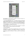
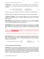
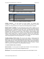
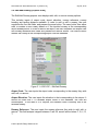
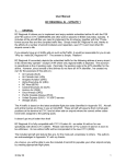
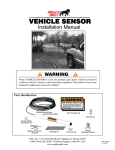
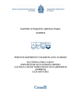
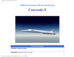
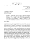
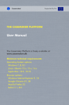
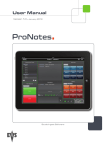
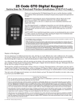
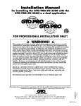
Document Ref: SRS-USR-002 Rev. 3 [Version 1.0] July 28, 2015 Specific Range Solutions Ltd. “Your partner in flight operations optimization” [email protected] www.srs.aero iPad A320 Landing Distance Calculator App User’s Manual 1.0 Summary The iPad A320 Landing Distance Calculator App allows the user to quickly calculate the landing distance required and approach speed (VAPP) based on aircraft configuration, airport and runway selection, runway surface condition, and airport weather data. The runway wind components are also calculated. The app is applicable to the Airbus A319, A320 and A321 aircraft models. Failure cases are not included. The app has been designed to be accurate, fast and pilot-friendly. *** Note: The app is for evaluation purposes only; i.e. NOT FOR OPERATIONAL USE. The input selections and fields comprise: Aircraft Configuration: o Autobrake Mode o Configuration o Operative Thrust Reversers Setting o Margin Setting o Aircraft Weight o Speed Increment Airport, Runaway and RSC Selection o Airport Code o Runway Selection o Runway Surface Condition or Reported CRFI Airport Wind Data (ATIS/AWOS) o Wind Direction o Wind Speed The airport selection also includes the ability to add, edit, or remove stored runways and to manually input basic runway information, such as landing distance available, runway heading and airport elevation for one-time use. This latter function is useful if a NOTAM is issued or if there is a need to land at an alternate airport. The app relates these inputs to aircraft in-flight performance data contained in the A319/A320/A321 Quick Reference Handbook (QRH) to provide the approach speed, landing distance available, landing distance required, and a status message indicating whether the landing distance available is sufficient or not. The headwind or tailwind and left or right crosswind components are also calculated. © 2015 Specific Range Solutions Ltd. 1 Document Ref: SRS-USR-002 Rev. 3 [Version 1.0] July 28, 2015 The application was designed to be pilot-friendly by incorporating the following features: Black text on a light grey background for the labels Black text on a light green background for the input fields Blue segmented control button with a light green background Blue text on a light green background for the “Calculate” button Black text on a light blue background for the output fields In-app brightness control The A320 Landing Distance Calculator App is designed and optimized for the iPad running iOS 8.3. To increase simplicity and ease of use, the app is composed of a single view with two popover views. The main view is for the input of aircraft configuration, airport and runway selection, runway surface condition, as well as airport weather data, and outputs of approach speed (VAPP), landing distance available, landing distance required, as well as runway wind components. The popover views are for the Edit/Add Runway and Runway Manual Input functions. *** Note: The accuracy of the results depends on the accuracy of the data input by the user. Aircraft Configuration, Airport, Runway and RSC Selection, Airport Weather Data, and Results of Calculation [Main View] Figure 2.1: A320 LDC [Non-Default View] © 2015 Specific Range Solutions Ltd. Figure 2.2: A320 LDC [Non-Default View] 2 Document Ref: SRS-USR-002 Rev. 3 [Version 1.0] July 28, 2015 Figure 2.3: A320 LDC – App Information App Information: The app information is available by selecting the information icon next to the title. The app information message is: "*** NOT FOR OPERATIONAL USE *** For evaluation purposes only with aircraft weight intentionally limited from 50,000 kg to 60,000 kg. App based on publicly available in-flight performance data for A319/A320/A321 aircraft equipped with CFM565B6 engines. Five Canadian and five U.S. airports with their runways are preloaded into the app: CYYZ , CYVR, CYYC, CYUL, CYEG, KATL, KLAX, KDFW, KORD and KJFK. To provide feedback or to request additional information, please contact Omer Majeed at [email protected]. Our website: www.srs.aero” Brightness Control: The built-in control function allows the brightness to be adjusted for day or night lighting conditions according to the user’s preference. 2.1 Aircraft Configuration Autobrake Mode: The user selects the autobrake mode to be used for the landing. The options are Autobrake On – Mode Medium, Autobrake On – Mode Low, and Autobrake Off. The default setting is Autobrake Off. Autobrake Off results in the shortest landing distance and Autobrake On – Mode Low results in the longest landing distance. © 2015 Specific Range Solutions Ltd. 3 Document Ref: SRS-USR-002 Rev. 3 [Version 1.0] July 28, 2015 Configuration: The user selects the aircraft configuration, either Configuration 3 or Configuration Full. The aircraft configuration affects the approach speed per Equation 1 as follows: ܸ + ܵݐ݊݁ ݉݁ݎܿ݊ܫ ݀݁݁ ܸ = ൜ ௌ ܸோாி + ܵݐ݊݁ ݉݁ݎܿ݊ܫ ݀݁݁ , ݊݅ݐܽݎݑ݂݃݅݊ܥ3 , ݈݈ݑܨ ݊݅ݐܽݎݑ݂݃݅݊ܥ (1) Where VLS and VREF are calculated as a function of configuration and aircraft weight. The default setting is Configuration Full which provides the shortest landing distance. 2 Reversers Operative: The user selects whether the two thrust reversers are operative. The default setting is 2 Reversers Operative which results in the shortest landing distance. Margin Setting: The user selects a margin of either 0% or 15%. The margin is applied to the total landing distance required. The default setting is set to 15% to ensure a conservative result independent of landing configuration. Aircraft Weight: The user inputs the aircraft weight in kg. The app has a valid aircraft weight range of 40,000 kg to 80,000 kg for the configuration with autobrake, and 40,000 kg to 76,000 kg for the configuration without autobrake. The default weight is 50,000 kg. *** Note: This evaluation version of the app has an intentionally limited input aircraft weight range from 50,000 kg to 60,000 kg. If the weight range is exceeded, the following status message is posted: AIRCRAFT WEIGHT INTENTIONALLY LIMITED FROM 50,000 KG TO 60,000 KG Speed Increment: The user inputs the speed increment above the approach speed in knots. The speed increment is used to adjust the approach speed, as can be seen in Equation 2. The default value is 0 kts. The speed increment also affects the landing distance required as follows: + 6% ܵ = ݊݅ݐܿ݁ݎݎܥݐ݊݁ ݉݁ݎܿ݊ܫ ݀݁݁ቄ + 8% , ݁݇ܽݎܾݐݑܣ , ܹ ݅ݐℎ݁݇ܽݎܾݐݑܣݐݑ (2) 2.2 Airport, Runway and RSC Selection Airport Code: The user inputs the desired arrival airport’s four-letter ICAO code. This code is used to populate the runway selection picker view, as well as to provide the airport elevation correction, for Canadian airports, to be added to the landing distance required. It should be noted that the app is preloaded with the following five Canadian airports and their runways per Table 2.1 and five U.S. airports and their runways per Table 2.2. These are the busiest airports in the two countries. © 2015 Specific Range Solutions Ltd. 4 Document Ref: SRS-USR-002 Rev. 3 [Version 1.0] ICAO Code CYEG CYUL CYVR CYYC CYYZ July 28, 2015 Airport Edmonton International Airport Montréal-Pierre Elliot Trudeau International Airport Vancouver International Airport Calgary International Airport Toronto Pearson International Table 2.1: Canadian Airports Preloaded in Database ICAO Code KATL KDFW KJFK KLAX KORD Airport Hartsfield-Jackson Atlanta International Airport Dallas/Fort Worth International Airport John F. Kennedy International Airport Los Angeles International Airport O'Hare International Airport Table 2.2: U.S. Airports Preloaded in Database Runway Selection: The user selects the active runway. The runways listed correspond to the airport’s ICAO code. The runway selection provides the runway heading, the runway elevation for U.S. airports and the landing distance available. Runway Surface Condition: The user selects the runway surface condition for the landing runway. As described in the FAA TALPA/ARC document, the landing distance performance data is determined during flight tests, and demonstrate the shortest landing distance required as a function of aircraft weight. This can result in high touchdown sink rates and approach angles, and maximum manual breaking being initiated as soon as possible. The TALPA/ARC also indicates that the contaminated runway landing distance data is determined analytically using the dry runway data. Therefore, the performance data landing distances are shorter than those achieved under normal operations, hence the optional use of 15% of margin. Canadian Runway Friction Index: The user has the option to directly input the reported CRFI value in lieu of selecting the runway surface condition. The CRFI data is taken directly from the Canada Flight Supplement and is based on the unfactored dry runway landing distance. If reverse thrust is not selected, Table 1 data from the CFS is employed. If reverse thrust is selected, Table 2 data from the CFS is employed. Margin (15%), if selected, is then applied to the landing distance required. 2.3 Airport Weather Data (ATIS/AWOS) Wind Direction: The user inputs the reported wind direction at the arrival airport in degrees magnetic or true if the runway is designated as such. Wind Speed: The user inputs the reported wind speed at the arrival airport in knots. © 2015 Specific Range Solutions Ltd. 5 Document Ref: SRS-USR-002 Rev. 3 [Version 1.0] July 28, 2015 2.4 Results of Calculation Calculate: Once the user presses the “Calculate” button, the results of calculation are displayed. VAPP: The approach speed is output in knots and is a function of selected aircraft configuration, aircraft weight, and speed increment. It is output once these three inputs are completed using Equation 1, where VLS and VREF are interpolated with respect to aircraft weight. It should be noted that the QRH only provides a VLS and VREF range of 44,000 kg to 76,000 kg, while the performance data has a range of 40,000 kg to 80,000 kg. With aircraft weights lower than 44,000 kg, the VLS and VREF speeds used are equivalent to those of 44,000 kg. However, with aircraft weights higher than 76,000 kg, the VLS and VREF speeds were extrapolated. This was done to ensure a more conservative solution. Headwind (Tailwind) Component: Based on the reported wind direction and speed, and the selected runway, the headwind or tailwind component is calculated and then displayed. If the calculated tailwind component exceeds 10 kts, then the Tailwind Component > 10 (kts) message is also displayed. Left (Right) Crosswind Component: Based on the reported wind direction and speed, and the selected runway, the left or right crosswind component is calculated and then displayed. The Left Crosswind Component (kts) or Right Crosswind Component (kts) message is displayed as required. Landing Distance Available: The landing distance available is displayed based on the input airport code and selected runway. This value is also used in order to determine which status message to display. Landing Distance Required: The landing distance required is displayed based on the inputs of aircraft configuration, weight, airport and runway selection, runway surface condition, airport weather data, and includes all corrections. Status Message: The status message displays whether the selected runway length is sufficient. If the landing distance available is greater than or equal to the landing distance required a Go message is displayed. However, if the landing distance available is less than the landing distance required, a No-Go message is displayed. The three status messages are, "LANDING DISTANCE AVAILABLE IS LESS THAN LANDING DISTANCE REQUIRED" "LANDING DISTANCE AVAILABLE IS EQUAL TO LANDING DISTANCE REQUIRED" “LANDING DISTANCE AVAILABLE IS GREATER THAN LANDING DISTANCE REQUIRED" © 2015 Specific Range Solutions Ltd. 6 Document Ref: SRS-USR-002 Rev. 3 [Version 1.0] July 28, 2015 2.0 Edit/Add Runway [Popover View] The Edit/Add Runway popover view displays add, edit, or remove runway options. This includes inputs of airport code, airport elevation, runway reference, runway heading and landing distance available. In order to add or edit a runway, the user completes the five text fields, and presses the save button. The save button then either edits or creates a new runway based on if the inputted runway at the corresponding airport already exists. In order to remove an airport, the user completes the airport code and runway reference texts fields and presses the remove button. The remove button deletes the runway at the corresponding airport from the database. Figure 3.1: A320 LDC – Edit/Add Runway Airport Code: The user inputs the airport code corresponding to the runway they wish add, edit, or remove. Airport Elevation: The user inputs the elevation in feet corresponding to the airport. It should be noted that if a Canadian airport exists in the database, this field will autocomplete. In the case of U.S. airports, the elevation value is actually that of the selected runway. Runway Reference: The user inputs the runway reference they wish to add, edit, or remove. This field accepts integers between 0 and 36, as well as the letters C, G, L, R, T. © 2015 Specific Range Solutions Ltd. 7 Document Ref: SRS-USR-002 Rev. 3 [Version 1.0] July 28, 2015 Runway Heading: The user inputs the runway heading corresponding to the runway reference. It should be noted that if the runway exists in the database, this will autocomplete. Landing Distance Available: The user inputs the landing distance available corresponding to the runway reference. It should be noted that if the runway exists in the database, this field will autocomplete. Save: Once the five text fields are completed, the save button must be selected in order to add or edit the runway in the database. Remove Runway: Once the airport code and runway number are input, the remove runway button will remove the runway for the database. 4.0 Runway Manual Input [Popover View] The Runway Manual Input popover view displays the runway manual input option. This includes airport elevation, runway heading and landing distance available. This function takes precedence over the Add/Edit Runway popover because it is used as an override function to permit landing at a runway not in the database. When the user presses the Runway Manual Input button, the airport code text field clears. The user then completes the airport elevation, runway heading and landing distance available text fields, and presses the save button. Once the save button is pressed a status message appears on the main view indicating the entered values and that they are appropriately saved. Figure 4.1: A320 LDC – Runway Manual Input © 2015 Specific Range Solutions Ltd. 8 Document Ref: SRS-USR-002 Rev. 3 [Version 1.0] July 28, 2015 Airport Elevation: The user inputs the airport or runway elevation in feet (ft). Runway Heading: The user inputs the runway heading in degrees (deg.). Landing Distance Available: The user inputs the landing distance available in feet (ft). Save: Once the three text fields are completed. The save button must be selected in order to temporarily store the information. A status message appears on the main view indicating the entered values and that they are appropriately saved. 5.0 Support: If you have any questions, would like to report a problem or make any comments, please send an email to [email protected]. Thank you for using the iPad A320 Landing Distance Calculator App. We appreciate your support and encourage your feedback. [Version 1.0, Build 1] © 2015 Specific Range Solutions Ltd. 9